

Page 1
RP/IS-A-C400/C500
Reduced Pressure
Zone Assemblies
Reduced Pressure
Detector Assemblies
Sizes: 21⁄2" – 10" (65 – 250mm)
• Installation
• Service
• Repair Kits
• Maintenance
For other repair kits and service parts,
send for Ames Repair Parts Price List,
PL-A-RP-BPD.
For technical assistance, contact your
local Ames representative.
IMPORTANT: Inquire with governing
authorities for local installation requirements.
NOTE: For Australia and New Zealand, line
strainers should be installed between the
upstream shutoff valve and the inlet of the
backflow preventer.
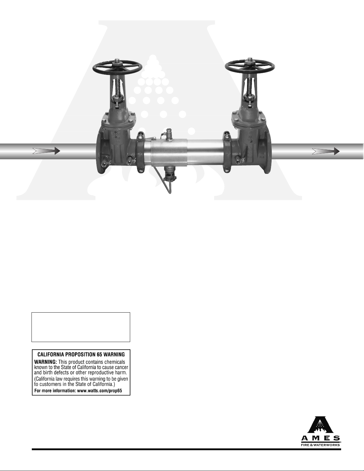
Colt
™
Series C400, C500
It’s important that this device be tested
periodically in compliance with local codes,
but at least once per year or more as service
conditions warrant. If installed on a fire
sprinkler system, all mechanical checks,
such as alarm checks and backflow
preventers, should be flow tested and
inspected internally in accordance with NFPA
13 and NFPA 25.
C400 OSY
Installation Note: Due to shipping, storage,
and general handling, the Victaulic Coupling
for the shutoff valves may have loosened
and should be retightened during installation.
Limited Warranty: Ames Fire & Waterworks (the “Company”) warrants each product to be free from defects in material and
workmanship under normal usage for a period of one year from the date of original shipment. In the event of such defects within
the warranty period, the Company will, at its option, replace or recondition the product without charge.
THE WARRANTY SET FORTH HEREIN IS GIVEN EXPRESSLY AND IS THE ONLY WARRANTY GIVEN BY THE COMPANY WITH
RESPECT TO THE PRODUCT. THE COMPANY MAKES NO OTHER WARRANTIES, EXPRESS OR IMPLIED. THE COMPANY HEREBY
SPECIFICALLY DISCLAIMS ALL OTHER WARRANTIES, EXPRESS OR IMPLIED, INCLUDING BUT NOT LIMITED TO THE IMPLIED
WARRANTIES OF MERCHANTABILITY AND FITNESS FOR A PARTICULAR PURPOSE.
The remedy described in the first paragraph of this warranty shall constitute the sole and exclusive remedy for breach of warranty,
and the Company shall not be responsible for any incidental, special or consequential damages, including without limitation, lost
profits or the cost of repairing or replacing other property which is damaged if this product does not work properly, other costs
resulting from labor charges, delays, vandalism, negligence, fouling caused by foreign material, damage from adverse water
conditions, chemical, or any other circumstances over which the Company has no control. This warranty shall be invalidated by
any abuse, misuse, misapplication, improper installation or improper maintenance or alteration of the product.
Some States do not allow limitations on how long an implied warranty lasts, and some States do not allow the exclusion or limitation
of incidental or consequential damages. Therefore the above limitations may not apply to you. This Limited Warranty gives you
specific legal rights, and you may have other rights that vary from State to State. You should consult applicable state laws to
determine your rights. SO FAR AS IS CONSISTENT WITH APPLICABLE STATE LAW, ANY IMPLIED WARRANTIES THAT MAY NOT
BE DISCLAIMED, INCLUDING THE IMPLIED WARRANTIES OF MERCHANTABILITY AND FITNESS FOR A PARTICULAR PURPOSE,
ARE LIMITED IN DURATION TO ONE YEAR FROM THE DATE OF ORIGINAL SHIPMENT.
www.amesfirewater.com
A Division of Watts Water Technologies, Inc.
Page 2
2
Guidelines
1. Most field problems occur because dirt and debris present
in the system at the time of installation becomes trapped in
the #1 check. The system should be flushed before the
valve is installed. If the system is not flushed until after the
valve is installed, remove both check modules from the
valve and open the inlet shutoff to allow water to flow for a
sufficient time to flush debris from the water line. If debris in
the water system continues to cause fouling, a strainer can
be installed upstream of the backflow assembly.
2. The Series C400 and C500 may be installed in either
horizontal, “N” pattern, or “Z” pattern position as long as the
backflow assembly is installed in accordance with the direction of the flow arrow on the assembly and the local water
authority approves the installation.
3. The assembly should be installed with adequate clearance
around the valve to allow for inspection, testing and servicing.
12" (300mm) should be the minimum clearance between the
lower portion of the assembly and the floor or grade. The
valve should be protected from freezing.
4. Installing a backflow preventer in a pit or vault is not
recommended.
5. Normal discharge and nuisance spitting are accommodated
by the use of an Ames air gap fitting and a fabricated indirect
waste line. Floor drains of the same size must be provided in
case of excessive discharge.
6. The C400 and C500 backflow preventer should be tested by
a certified tester at the time of installation.
Note: Assembly body should not be painted.
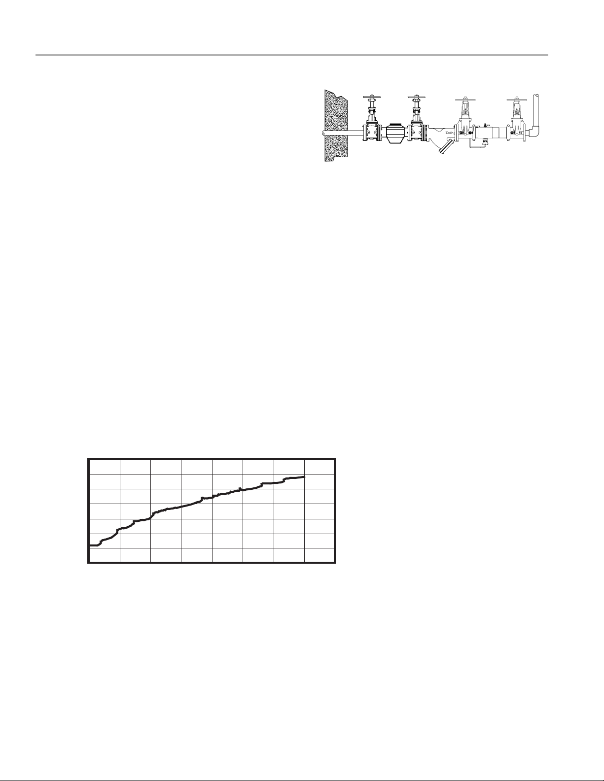
Horizontal Installation
Basic Installation Instructions
Relief Valve Discharge Rates
2
1
⁄2" – 10" (65-250mm) C400 and C500
lpm gpm
1330 350
1140 300
950 250
760 200
570 150
380 100
190 50
00
0 20 40 60 80 psi
0 138 276 413 551 kPa
Rate of Flow
Pressure
Page 3
3
Prior to servicing any Ames valve, it is mandatory to
shut down the water system by closing both the inlet
and outlet shutoff valves. After shutoff valves are closed,
open test cock #2, #3 and #4 to relieve pressure within
the backflow assembly.
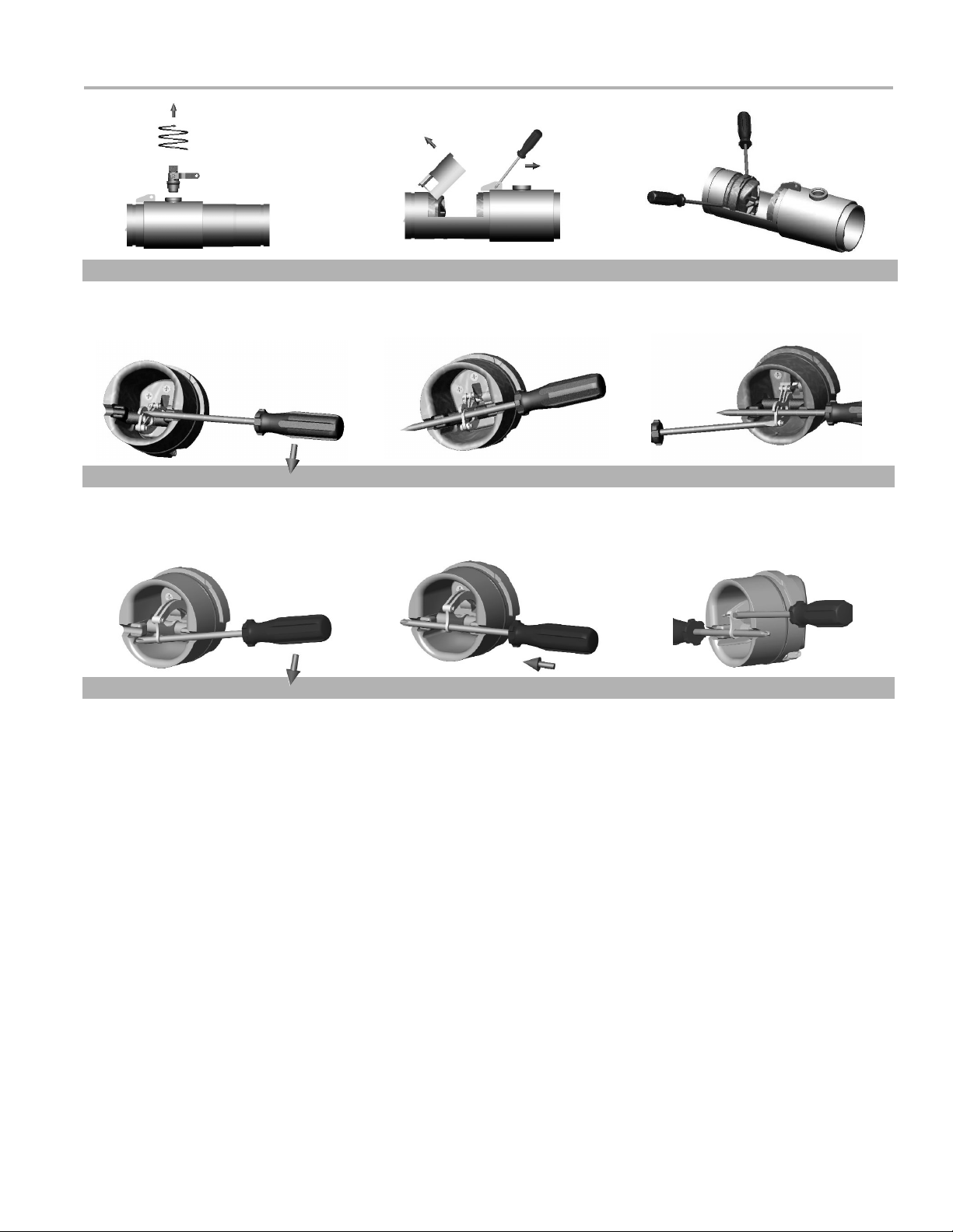
1. After #3 test cock has been opened to relieve pressure,
remove #3 test cock from housing. (Figure A)
2. Insert a #3 screwdriver through the hole on the top of the
cover sleeve and using both hands rotate the cover sleeve
approximately
1
/4-turn clockwise and 1/4-turn counter-clockwise to break the sleeve O-ring seals. Using the screwdriver,
slowly slide the cover sleeve to the downstream side of the
housing. (Figure B)
3. Remove the stainless steel check retainer from the housing.
(Figure B)
4. Remove the #1 check module (Figure C) by inserting two
flat blade screwdrivers into the slots on either side of the
check module and gently pry the check module toward
the open zone.
5. Remove #2 check module with the same instructions as
in #4 above. For servicing 6" (150mm) checks see 8" – 10"
(200 – 250mm) instructions on p.4.
6. To clean or inspect either check module, insert a #3 screwdriver through the downstream side of the check module
as shown in Figures D and E. When the screwdriver is in
place, remove the E-clip (Figure F) and pin connecting the
structural members and the check clapper will open with
no tension.
7. Thoroughly clean the seating area. The sealing disc may be
removed, if necessary, by removing the screws connecting
the keeper plate to the clapper. The sealing disc may be
reversed and reinstalled if the elastomer is cut or damaged.
8. Wash check module and O-ring and inspect for any
damage. If damaged, reinstall new parts.
9. After thorough cleaning, lubricate O-ring w/FDA approved
lubricant, replace pin and E-clip in structural members,
remove screw driver, reinstall check modules and
assemble housing in reverse order of these instructions.
Figure D
Figure E
Figure F
Figure A
Figure B
Figure C
Figure D
Figure E
Figure F
#1 Check Diagrams
#2 Check Diagrams
Maintenance Instructions 21/2" – 6" (65 – 150mm)
Instructions
Page 4

4
Material/Tool Requirements:
• #4 Phillips screwdriver or 3/8" diameter rod, length sufficient to span diameter of
check, see Figures A and B.
•
1
/2 – 13 x 5 fully threaded hex bolt (Service bolt).
•
3
/4" open end or socket wrench.
Instructions:
Prior to servicing any Ames valve, it is mandatory to shut down the water system by
closing both the inlet and outlet shutoff valves. After shutoff valves are closed, open
test cock #2, #3 and #4 to relieve pressure within the backflow assembly.
1. After #3 test cock has been opened to relieve pressure, remove #3 test cock from
housing. When repairing an 8" or 10" (200 – 250mm) device, remove both Victaulic
couplers from body. Slide the downstream Victaulic coupler gasket to the downstream side of the housing. The upstream Victaulic coupler gasket stays in place.
2. Remove check(s) to be maintenanced.
3. Locate the service hole and thread in the service bolt by hand until it contacts the
linkage. (Figure A)
4. Continue to thread in service bolt with the wrench until the service hole in the linkage is
aligned with the service notches on the spring arbors. (Figure A)
5. Insert the Phillips screwdriver through the arbors and service hole of the linkage
making sure that the tip of the screwdriver extends past the ends of the arbors by a
minimum of
1
/4" (6mm). (Figure B)
6. Back out the service bolt until load is transferred to the screwdriver. Continue to back
out the service bolt until sufficient clearance is achieved to remove the complete spring
mechanism.
7. To disconnect linkage, remove retaining clip and pin (store in a safe location
for reinstallation).
8. To remove spring mechanism, grasp the screwdriver at the center, pull complete
assembly straight out and store in a safe place.
9. Reinstall in reverse.
WARNING – While the spring mechanism is removed for check servicing; never pull
the screwdriver out or off the support notches on the arbors. Doing so may cause
bodily injuries.
Maintenance Instructions 8" – 10" (200 – 250mm)
Figure A
Figure B
Service Hole
Page 5

5
Servicing Relief Valve
Prior to servicing the relief valve, it is mandatory to shut down
water system by closing both the inlet and outlet shutoff
valves and relieving pressure within the assembly by opening
the #2, #3 and #4 test cocks.
DO NOT REMOVE SPIDER BUSHING FOR SERVICING.
1. Disconnect the hose from the bottom cover plate to the relief
valve.
2. An O-ring seals the relief valve body to the main housing. It is
not necessary to tighten the connection beyond firm hand
tightening. The relief valve should be able to be removed by
hand untightening. Unscrew the relief valve from the housing.
3. Remove the cover plate of the relief valve by removing the
four connecting screws.
4. Remove the rubber diaphragm from the relief valve.
Be aware of how the diaphragm is configured so that it can
be reinstalled in the same manner. The hard rubber tab in the
diaphragm fits into a similar socket in the head of the piston.
(Figure 1)
Test No.1
Purpose: To test check valve No. 2 for tightness against
reverse flow.
Requirements: Valve must be tight against reverse flow under
all pressure differentials. Slowly open the ‘high’ valve A and
the ‘vent’ valve C, and keep the ‘low’ valve B closed. Open
test cock #4. Indicated pressure differential will decrease
slightly. If pressure differential continues to decrease (until
the vent opens) check valve #2 is reported as ‘leaking’.
Test No. 2
Purpose: To test shutoff #2 for tightness.
Requirements: After passing Test No. 1, continue to Test No. 2
by closing test cock #2. The indicated pressure differential will
decrease slightly. If pressure differential continues to decrease
(approaching ‘zero’), shutoff #2 is reported to be ‘leaking’.
Test No. 3
Purpose: To test check Valve No. 1 for tightness.
Requirements: Valve must be tight against reverse flow under
all pressure differentials. Close ‘high’ valve A and open test
cock #2. Close test cock #4. Disconnect vent hose at test
cock #4. Open valves B and C, bleeding to atmosphere. Then
closing valve B restores the system to a normal static condition.
Observe the pressure differential gauge. If there is a decrease in
the indicated value, check valve No. 1 is reported as ‘leaking’.
Test No. 4
Purpose: To test operation of pressure differential relief valve.
Requirements: The pressure differential relief valve must
operate to maintain the ‘zone’ between the two check valves at
least 2psi less than the supply pressure. Close ‘vent’ valve C.
Open ‘high’ valve A. Open the ‘low’ valve B very slowly until the
differential gauge needle starts to drop. Hold the valve at this
position and observe the gauge reading at the moment the first
Figure 1
Figure 2
discharge is noted from the relief valve. Record this as the
opening differential pressure of the relief valve.
Note: It is important that the differential gauge needle drops slowly.
Close test cocks #2 and #3. Use ‘vent’ hose to relieve pressure from
test kit by opening valves A, B and C Remove all test equipment and
open shutoff #2.
5. Hold the relief valve in both hands with the threaded end up
and both thumbs on the head of the piston. Push up on the
piston until the piston shaft with the attached E-clip is
exposed. Remove the E-clip (Figure 2)
6. Remove the piston and spring from the relief valve housing
and thoroughly clean all parts including the diaphragm.
Inspect all rubber parts for damage and if damaged, replace
them with new parts.
7. Reassemble the relief valve in the reverse order that it
was disassembled.
Testing — Reduced Pressure Zone Assemblies
Ball Type Test Valves
A
C
B
Needle
Valve
High Hose
(Yellow)
Low Hose
(White or Red)
Vent Hose
(Blue)
Test Cock Test Cock Test Cock Test Cock
No. 1 No. 2 No.3 No.4
Page 6

6
Replacement Parts Listing
ITEM DESCRIPTION ORDERING ORDERING ORDERING
NO. CODE 21⁄2" (65MM) CODE 3" (80MM) CODE 4" (100MM)
1. First Check Module (EPDM) 7018112 7018112 7018112
1. First Check Module (Red Silicone) 7018760 7018760 7018760
2. Second Check Module (a) (EPDM) 7018120 7018120 7018120
2. Second Check Module (a) (Red Silicone) 7018764 7018764 7018764
3. O-ring, Check Module 7017861 7017861 7017861
4. Disc, Elastomer Shut Off (EPDM) 7018329 7018329 7018329
4. Disc, Elastomer Shut Off (Red Silicone) 7017855 7017855 7017855
5. Grooved Clevis Pin Kit
(Contains: “E” Clip & Clevis Pin - 5 per pack) 7018126 7018126 7018126
6. Closure Sleeve Test-Cock with O-ring 7018152 7018152 7018152
7. Closure Sleeve 7017881 7017881 7017881
8. Sleeve O-ring or Gasket (2 req’d) 7017896 7017896 7017896
9. Relief Valve Assembly (Hose included) 7018107 7018107 7018107
NS Check Repair Kit
(Contains: O-ring, Shutoff EPDM Disc & “E” clip) 7018391 7018391 7018391
NS Check Repair Kit
(Contains: O-ring, Shutoff Red Silicone Disc & “E” clip) 7018123 7018123 7018123
NS “E” Clip 7017870 7017870 7017870
NS Test Cock, .50 FPT x FPT with Nipple 7018394 7018394 7018394
NS Test Cock, .75 FPT x FPT with Nipple N/A N/A N/A
NS Groove Coupler (Shutoff) 7017994 7017995 7018147
NS Groove Coupler Gasket 7018882 7018883 7018884
NS Sleeve Coupler Assembly N/A N/A N/A
NS Air Gap Drain 7018367 7018367 7018367
NS Splash Guard (only) 7018894 7018894 7018894
NS O-ring, #3 Test Cock 7017897 7017897 7017897
NS Stainless Steel Check Retainer 7018408 7018408 7018408
ITEM DESCRIPTION ORDERING ORDERING ORDERING
NO. CODE 6" (150MM) CODE 8" (200MM) CODE 10" (250MM)
1. First Check Module (EPDM) 7018115 — —
1. First Check Module (Red Silicone) 7018761 7018118 7018401
2. Second Check Module (a) (EPDM) 7018121 — —
2. Second Check Module (a) (Red Silicone) 7018765 7018119 7018402
3. O-ring, Check Module 7017910 7013301 7018352
4. Disc, Elastomer Shut Off (EPDM) 7017903 — —
4. Disc, Elastomer Shut Off (Red Silicone) 7017903 7017928 7018348
5. Grooved Clevis Pin Kit 7018127 7018127 7018412
(Contains: “E” Clip & Clevis Pin - 5 per pack)
6. Closure Sleeve Test-Cock with O-ring 7018153 7018153 7018153
7. Closure Sleeve 7017883 7017885 7017887
8. Sleeve O-ring or Gasket (2 req’d) 7017921 7017944 7018339
9. Relief Valve Assembly (Hose included) 7018107 7018107 7018107
NS Check Repair Kit
(Contains: O-ring, Shutoff EPDM Disc & “E” clip) 7018392 — —
NS Check Repair Kit
(Contains: O-ring, Shutoff Red Silicone Disc & “E” clip) 7018124 7018125 7018414
NS “E” Clip 7017821 7017821 7017974
NS Test Cock, .50 FPT x FPT with Nipple N/A N/A N/A
NS Test Cock, .75 FPT x FPT with Nipple 7018395 7018395 7018395
NS Groove Coupler (Shutoff) 7018148 7018149 N/A
NS Groove Coupler Gasket 7013248 7013308 N/A
NS Sleeve Coupler Assembly N/A 7018122 7018413
NS Air Gap Drain 7018367 7018367 7018367
NS Splash Guard (only) 7018894 7018894 7018894
NS O-ring, #3 Test Cock 7017897 7017897 7017897
NS Stainless Steel Check Retainer 7018409 7018410 7018411
1
3
9
8
7
2
5
4
6
Page 7

7
Troubleshooting Guide
Difficulty Possible Cause Correction
#1 check is fouled Remove and clean #1 check
Relief valve discharges water Relief valve does not properly close Service relief valve
while system is not flowing
Municipal water pressure is fluctuating Install check valve upstream
of backflow assembly
Fouled relief valve seat Service relief valve
Relief valve does not Incorrectly installed diaphragm Remove diaphragm and
shut off properly correctly install
Damaged rubber surface on piston Replace with new piston
Damaged or plugged pressure hose Repair or replace hose.
Relief Valve Replacement Parts Listing
ITEM DESCRIPTION ORDERING
NO. CODE
1. Relief Valve Assembly 7018107
2. Diaphragm, RV 7017809
3. Spring, RV 7013368
4. Spider Bushing, RV 7017811
5. Piston Assembly, RV* 7018227
6. Body, RV 7018889
7. Hose & Cover Plate Assembly 7018228
8. Screw, Cover RV 7017822
9. O-ring, Inlet coupler 7017826
10. ‘E’ Clip (5 per pack) 7017870
NS Sensing Elbow 7018888
ITEM DESCRIPTION USE FOR ORDERING
NO. CODE
NS Hose (1/2"x20") 21⁄2" & 3 M400, M500 7018890
NS Hose (1/2"x24") 21⁄2" & 3 M400 N & Z 7018891
NS Hose (
1
/2"x30") 6 M400, 2.5, 3, 4 M500, 7018892
21⁄2", 3, 4 M400 N & Z,
21⁄2", 3, 4 M500 N & Z,
21⁄2" & 3 M500 N & Z BFG
NS Hose (
1
/2"x36") 8 & 10 M400, 7018893
6, 8, 10 M400 N & Z,
4 & 6 M400BFG N & Z,
6, 8, 10 M500,
6, 8, 10 M500 N & Z
4 & 6 M500BFG N & Z
*includes shutoff disc
1
6
7
2
9
10
4
3
5
8
Page 8

For additional information, visit our web site at: www.amesfirewater.com
RP/IS-A-C400/C500 0904 EDP#7018381 ©Ames Fire & Waterworks 2009
www.amesfirewater.com
A Division of Watts Water Technologies, Inc.
USA: Backflow- 1427 N. Market Blvd • Suite #9 • Sacramento, CA 95834 • T: 916-928-0123 • F: 916-928-9333
Control Valves- 18550 Hansen Road • Houston, TX 77075 • T: 713-943-0688 • F: 713-944-9445
Canada: 5435 North Service Rd. • Burlington, ONT. L7L 5H7• T: 905-332-4090 • F: 905-332-7068
 Loading...