

Page 1
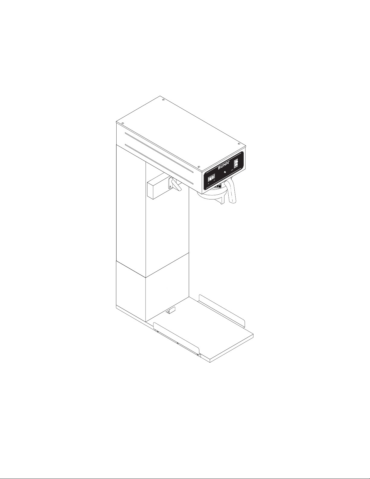
BUNN
®
TU3Q-EZ
OPERATING & SERVICE MANUAL
BUNN-O-MATIC CORPORATION
POST OFFICE BOX 3227
SPRINGFIELD, ILLINOIS 62708-3227
TELEPHONE: (217) 529-6601 FAX: (217) 529-6644
29460.0000C 8/00 © 1999 Bunn-O-Matic Corporation
Page 2

CONTENTS
Introduction .............................................................. 2
Warranty ................................................................... 2
User Notices ............................................................. 3
Electrical Requirements ............................................ 4
Plumbing Requirements ........................................... 4
Initial Set-Up............................................................. 5
Operating Controls.................................................... 6
Cleaning.................................................................... 6
Tea Brewing .............................................................. 6
Adjustments and Optional Settings........................... 7
Troubleshooting ........................................................ 8
Service.................................................................... 14
Wiring Schematic ................................................... 22
INTRODUCTION
This equipment will brew a three-gallon batch of fresh tea into an awaiting dispenser. The tea will be dispensed at
approximately room temperature to conserve ice. The brewer is only for indoor use on a sturdy counter or shelf.
WARRANTY
Bunn-O-Matic Corp. (“Bunn”) warrants the equipment manufactured by it to be commercially free from defects in
material and workmanship existing at the time of manufacture and appearing within one year from the date of installation.
In addition:
1.) Bunn warrants electronic circuit and/or control boards to be commercially free from defects in material and work-
manship for two years from the date of installation.
2.) Bunn warrants the compressor on refrigeration equipment to be commercially free from defects in material and
workmanship for two years from the date of installation.
3.) Bunn warrants that the grinding burrs on coffee grinding equipment will grind coffee to meet original factory screen
sieve analysis for three years from date of installation or for 30,000 pounds of coffee, whichever comes first.
This warranty does not apply to any equipment, component or part that was not manufactured by Bunn or that, in
Bunn’s judgement, has been affected by misuse, neglect, alteration, improper installation or operation, improper maintenance or repair, damage or casualty.
THE FOREGOING WARRANTY IS EXCLUSIVE AND IS IN LIEU OF ANY OTHER WARRANTY, WRITTEN OR ORAL,
EXPRESS OR IMPLIED, INCLUDING, BUT NOT LIMITED TO, ANY IMPLIED WARRANTY OF EITHER MERCHANTABILITY
OR FITNESS FOR A PARTICULAR PURPOSE. The agents, dealers or employees of Bunn are not authorized to make
modifications to this warranty or to make additional warranties that are binding on Bunn. Accordingly, statements by such
individuals, whether oral or written, do not constitute warranties and should not be relied upon.
The Buyer shall give Bunn prompt notice of any claim to be made under this warranty by telephone at (217) 529-6601
or by writing to Post Office Box 3227, Springfield, Illinois, 62708-3227. If requested by Bunn, the Buyer shall ship the
defective equipment prepaid to an authorized Bunn service location. If Bunn determines, in its sole discretion, that the
equipment does not conform to the warranty, Bunn shall repair the equipment with no charge for parts during the warranty
period and no charge for labor by a Bunn Authorized Service Representative during the warranty period. If Bunn determines
that repair is not feasible, Bunn shall, at its sole option, replace the equipment or refund the purchase price for the equipment.
THE BUYER’S REMEDY AGAINST BUNN FOR THE BREACH OF ANY OBLIGATION ARISING OUT OF THE SALE OF THIS
EQUIPMENT, WHETHER DERIVED FROM WARRANTY OR OTHERWISE, SHALL BE LIMITED, AS SPECIFIED HEREIN, TO
REPAIR OR, AT BUNN’S SOLE OPTION, REPLACEMENT OR REFUND.
In no event shall Bunn be liable for any other damage or loss, including, but not limited to, lost profits, lost sales, loss
of use of equipment, claims of Buyer’s customers, cost of capital, cost of down time, cost of substitute equipment, facilities
or services, or any other special, incidental or consequential damages.
Page 2
29460 061599
Page 3
Page 3
Page 4

ELECTRICAL REQUIREMENTS
CAUTION - The brewer must be disconnected from the power source until specified in
120V model brewers require 2-wire, grounded service rated 120 volts ac, 15 amp, single phase, 60 Hz.
Proceed as follows:
Electrical Hook-Up
CAUTION – Improper electrical installation will damage electronic components.
1. An electrician must provide electrical service as specified.
2. Using a voltmeter, check the voltage at the electrical source.
3. Connect the brewer to the power source.
4. If plumbing is to be hooked up later be sure the brewer is disconnected from the power source. If plumbing
has been hooked up, the brewer is ready for
Initial Set-Up
.
Initial Set-Up.
PLUMBING REQUIREMENTS
These brewers must be connected to a cold water system with operating pressure between 20 (138) and 90
psi (620 kPa) from a 1⁄2" or larger supply line. A shut-off valve should be installed in the line before the brewer.
Install a regulator in the line when pressure is greater than 90 psi (620 kPa) to reduce it to 50 psi (345 kPa). The
water inlet fitting is 1⁄4" flare.
NOTE - Bunn-O-Matic recommends 1⁄4" copper tubing for installations of less than 25 feet and 3⁄8" for more than
25 feet from the 1⁄2" water supply line. A tight coil of copper tubing in the water line will facilitate moving the
brewer to clean the countertop. Bunn-O-Matic does not recommend the use of a saddle valve to install the
brewer. The size and shape of the hole made in the supply line by this type of device may restrict water flow.
This equipment must be installed to comply with the Basic Plumbing Code of the
Building Officials and Code Administrators International, Inc. (BOCA)
and the Food Service Sanitation Manual of the Food and Drug Administration (FDA).
Page 4
29460 061599
Page 5
PLUMBING REQUIREMENTS (cont.)
1. Remove the shipping cap from the bulkhead fitting on the rear of the brewer.
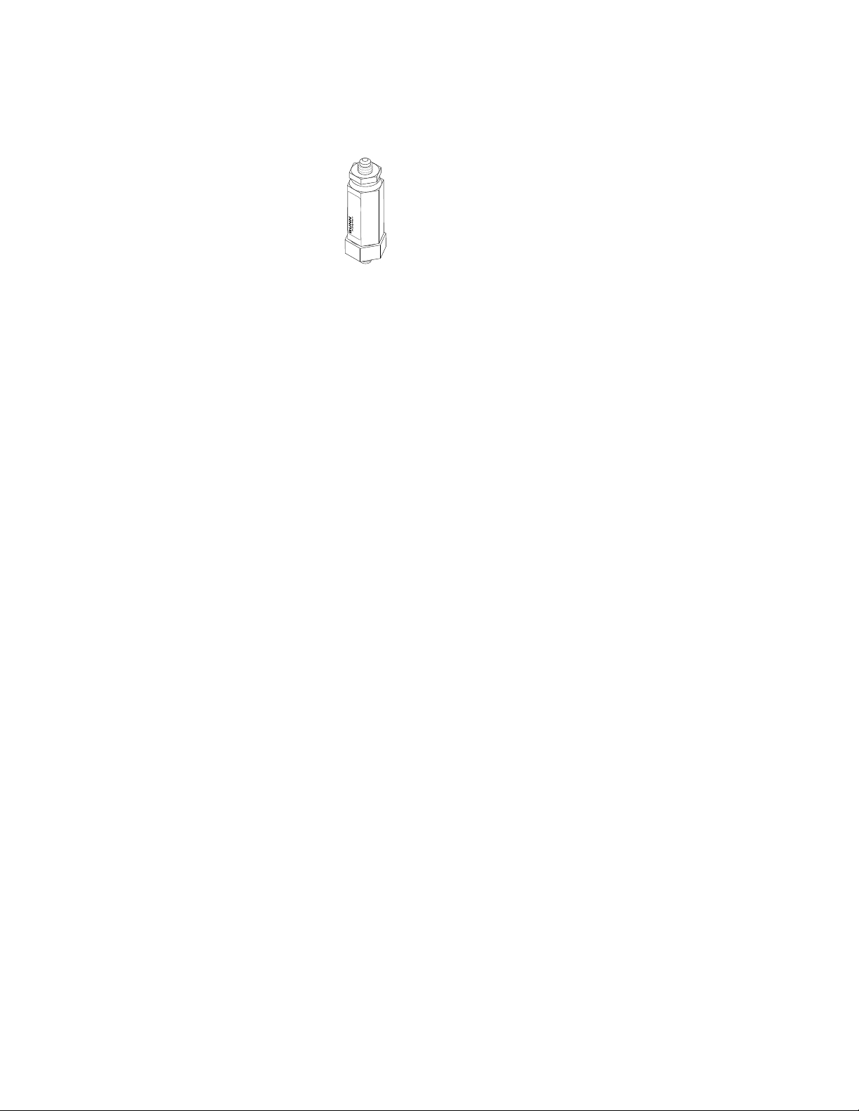
2. Attach the flare fitting from the short piece of tubing on the strainer/flow control (supplied) to the water inlet
fitting at the rear of the brewer.
3. Flush the water line and securely attach it to the flare fitting on the strainer/flow control.
4. Turn on the water supply.
Page 5
Page 6

OPERATING CONTROLS
A. ON/OFF Switch
ON - Placing the switch in the left position allows the start switch to activate a timed brew cycle for three gallons
of tea.
OFF - Placing the switch in the right position stops the brew cycle. Stopping a brew cycle after it has been started
will not stop the flow of water into the funnel until the tank syphons down to its proper level. The switch should
always be placed in this position after a brew cycle and whenever the brewer is unattended.
B. Start Switch
Starts a brew cycle when the ON/OFF switch is in the "ON" position.
C. Ready Indicator
This indicator glows when preselected brew water temperature has been achieved. It is also used for diagnostic
testing of brewer.
CLEANING
CAUTION - CLEAN AND SANITIZE YOUR ICED TEA BREWER DAILY
1. Remove and thoroughly clean the entire brew funnel. The funnel tip and screen must be free from any tea
particles or residue. Reassemble the funnel.
2. Place the ON/OFF switch in the "OFF" position. Remove and thoroughly rinse the sprayhead. The holes must
be open and clear of any mineral deposits. Wipe the sprayhead panel clean with a damp cloth.
3. Insert the deliming spring into the sprayhead fitting until no more than two inches is visible and move it in
and out 5 or 6 times. Reattach the sprayhead.
4. Wash the entire outside surface of the brewer with a clean damp cloth.
CAUTION - DO NOT KEEP BREWED ICED TEA OVERNIGHT. THE SERVER MUST BE CLEANED DAILY.
TEA BREWING
1. Begin each brew cycle with a clean empty brew funnel and server. (Be sure the server lid doesn’t interfere
with the flow of dilution water.)
2. Insert a BUNN® filter into the funnel.
3. Pour the packet of loose fresh tea leaves into the filter. Approximately four ounces is recommended.
4. Level the bed of tea leaves by gently shaking.
5. Slide the funnel into the funnel rails until it stops.
6. Place the ON/OFF switch in the "ON" position.
7. Momentarily press the start switch.
CAUTION - The funnel contains hot liquids. Remove funnel slowly.
8. Carefully remove the brew funnel and discard the used filter when tea no longer drips from the funnel tip.
9. Place the ON/OFF switch in the "OFF" position to prevent a false start.
10. Fresh tea is available at the faucet.
Page 6
29460 061599
Page 7
TU3Q-EZ ADJUSTMENTS & OPTIONAL SETTINGS
Page 7
Page 8

TROUBLESHOOTING
A troubleshooting guide is provided to suggest probable causes and remedies for the most likely problems
encountered. If the problem remains after exhausting the troubleshooting steps, contact the Bunn-O-Matic
Technical Service Department.
• Inspection, testing, and repair of electrical equipment should be performed only by qualified service person-
nel.
• All electronic components have 120 volt ac and low voltage dc potential on their terminals. Shorting of
terminals or the application of external voltages may result in board failure.
• Intermittent operation of electronic circuit boards is unlikely. Board failure will normally be permanent. If an
intermittent condition is encountered, the cause will likely be a switch contact or a loose connection at a
terminal or crimp.
• Solenoid removal requires interrupting the water supply to the valve. Damage may result if solenoids are
energized for more than ten minutes without a supply of water.
• The use of two wrenches is recommended whenever plumbing fittings are tightened or loosened. This will
help to avoid twists and kinks in the tubing.
• Make certain that all plumbing connections are sealed and electrical connections tight and isolated.
• This brewer is heated at all times. Keep away from combustibles.
WARNING • Exercise extreme caution when servicing electrical equipment.
• Unplug the brewer when servicing, except when electrical tests are specified.
• Follow recommended service procedures.
• Replace all protective shields or safety notices.
Before troubleshooting this brewer, check for the following:
A. Control Board
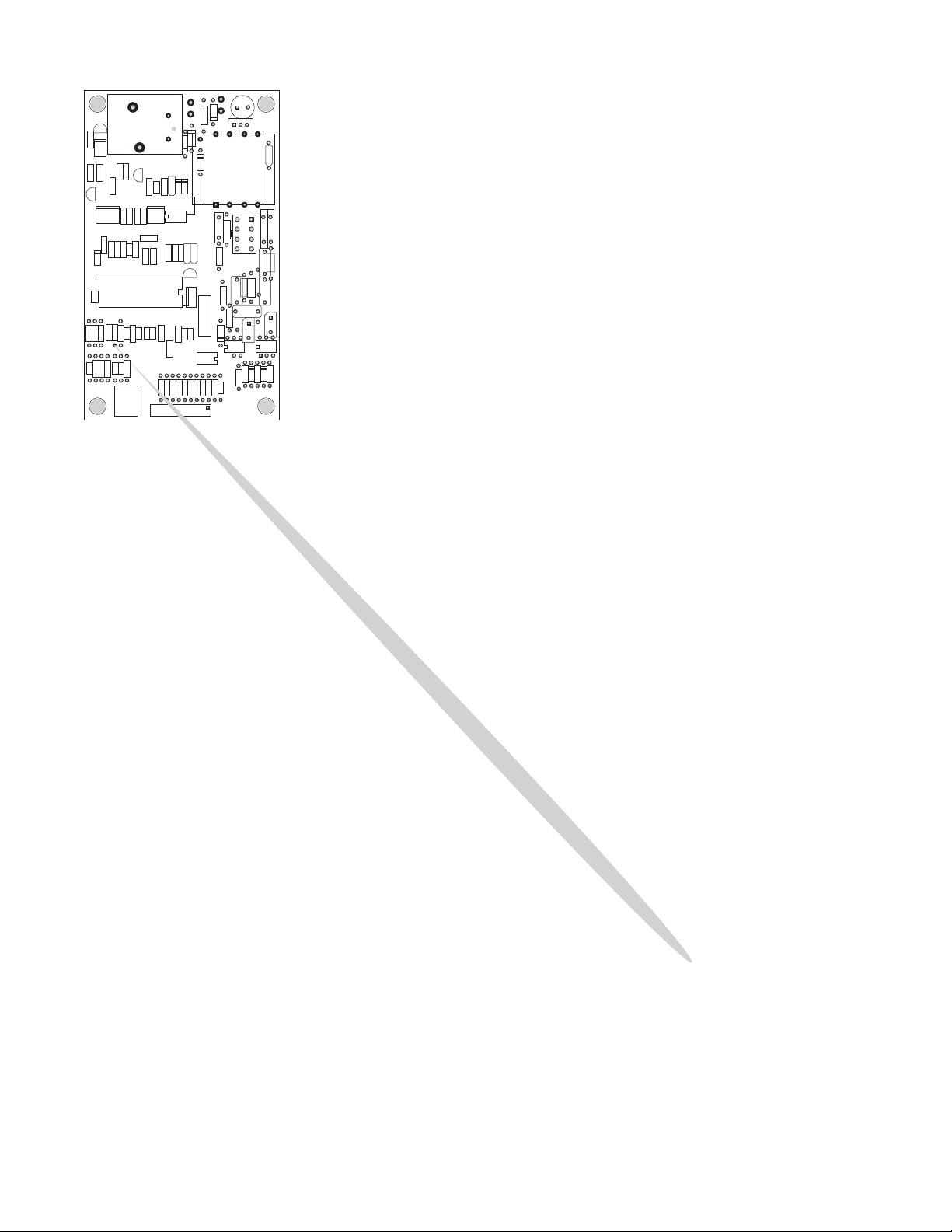
Locate J6 connector on control board. If jumper is across pins 1 & 2, board is set up to operate tea brewer
which does not use a refill system. See page 7 for proper jumper location.
B. Also make sure before servicing brewer that voltage is present at control board. Check for voltage across pins
1 & 7 of the eight pin J1 connector (black and white wires). If voltage is present, proceed with testing. If
voltage is not present, check wiring and voltage at socket. Correct the problem and retest before proceeding
with testing.
Page 8
29460 061599
Page 9

TROUBLESHOOTING (cont.)
BREWING CIRCUIT
PROBLEM
Ready light flashing
Brew cycle will not start
PROBABLE CAUSE REMEDY
1. Brewer has shut down due to
malfunction.
1. No water
Refer to
formation. See page 13
Water lines and valves to the brewer
must be open.
2. No power or incorrect voltage to
the brewer
Check for voltage across the black
and white terminals at the terminal
block.
3. ON/OFF switch not in the "ON" po-
The indicator lamp must be lit.
sition
4. Start Switch
Refer to
testing procedures. See page 18
5. Low water temperature (Brew
lockout is enabled)
Allow brewer to heat until ready
lamp is lit, or disable the brew lockout feature. See page 7
Diagnostic Chart
Service -
Start Switch for
for in-
6. Brew solenoid valve
7. Control Board
Refer to
Service -
Brew Solenoid
Valve for testing procedures. See
page 15
Attach a voltmeter to terminals J11 & J1-7 of the control board. Connect the brewer to the power
source. Voltage should be present.
Disconnect the brewer from the
power source. Attach a voltmeter
to terminals J1-1 and J1-8. Reconnect the brewer to the power
source. With the ON/OFF Switch in
the "ON" position, voltage should be
present. It should not be present in
the "OFF" position. If these readings
are not correct, replace the control
board assembly. See page 21
Page 9
29460 082300
Page 10

TROUBLESHOOTING (cont.)
BREWING CIRCUIT (cont.)
PROBLEM PROBABLE CAUSE REMEDY
Consistently low beverage level in
the dispenser or beverage overflows dispenser
1. Brew volume
2. Lime build up
3. Brew Solenoid Valve
4. Strainer/Flow Control
Refer to
Settings
Adjustments and Optional
to set brew volume. See
page 7. Using a stop watch or second hand, time the length of the
brew cycle. Record this time inside
the top lid. If service is ever needed
again, use the time as reference to
determine if time has changed.
Inspect the sprayhead tube and
sprayhead for excessive lime deposits. Delime as required.
Refer to
Service -
Brew Solenoid
Valve for testing procedures. See
page 15
A) Direction of flow arrow must be
pointing towards brewer.
B) Remove strainer/flow control
and check for obstructions. Clear
or replace.
Dripping from sprayhead
1. Lime build up
2. Brew Solenoid Valve
Inspect the tank assembly for excessive lime deposits. Delime as required.
Refer to
Service -
Brew Solenoid
Valve for testing procedures. See
page 15
Page 10
29460 082300
Page 11

TROUBLESHOOTING (cont.)
BREWING CIRCUIT (cont.)
PROBLEM PROBABLE CAUSE REMEDY
Weak beverage
1. Sprayhead
2. Water temperature
3. Filter type
4. Funnel loading
A seven-hole stainless steel sprayhead must be used for proper extraction.
Place an empty brew funnel on an
empty vessel of at least 4 gallons
beneath the sprayhead. Initiate
brew cycle and check the water
temperature immediately below the
sprayhead with a thermometer. The
reading must not be less than 5°F
(3°C) below set temperature. Adjust the temperature setting to increase the water temperature. Refer to
Adjustments and Optional
Settings
. See page 7
BUNN® paper filters must be used
for proper extraction.
The BUNN® paper filter must be
centered in the funnel and the bed
of tea leaves leveled by shaking
gently.
Drip out time too long
Dry tea leaves remain in the funnel
1. Funnel Tip
1. Sprayhead
2. Funnel loading
The brew funnel should be cleaned
thoroughly before each brew cycle
to lessen the chance of tea leaf particles clogging the funnel tip.
Make sure sprayhead is present and
holes are clear and unobstructed.
There should be seven separate
streams of water coming out of the
sprayhead.
The BUNN® paper filter must be
centered in the funnel and the bed
of tea leaves leveled by shaking
gently.
Page 11
29460 082300
Page 12

TROUBLESHOOTING (cont.)
HEATING CIRCUIT (cont.)
PROBLEM PROBABLE CAUSE REMEDY
Water does not heat to proper
temperature
IMPORTANT: Make sure no temperature tests are taken before the
ready light is "ON". Tank temperature must be stabilized before readings are taken.
Spitting or excessive steaming
1. Water not touching temperature
probe
2. Temperature Probe
3. Limit Thermostat
4. Tank Heater
1. Lime build up on temperature
probe, tank or tank heater
2. Temperature Probe
Remove probe and grommet. Look
into hole on tank lid. Water must
be within one inch from top of tank.
Refer to
Service -
Temperature
Probe for testing procedures. See
page 20
Refer to
Service -
Limit Thermostat
for testing procedures. See page 16
Refer to
Service -
Tank Heater for
testing procedures. See page 19
Inspect probe and tank assembly
for excessive lime deposits. Delime
as required.
Refer to
Service -
Temperature
Probe for testing procedures. See
page 20
Brewer is making unusual noises
3. Control Board
1. Plumbing lines
2. Water supply
3. Lime build up
Set the temperature to 205°F
(96°C). Let tank temperature stabilize. If temperature in tank is
above temperature setting by more
than 7°F (4°C), replace the control
board. See page 21
Plumbing lines should not rest on
the counter top.
The brewer must be connected to
a cold water supply.
Remove the tank lid and clean inside of tank with a deliming agent,
if necessary.
Page 12
29460 082300
Page 13
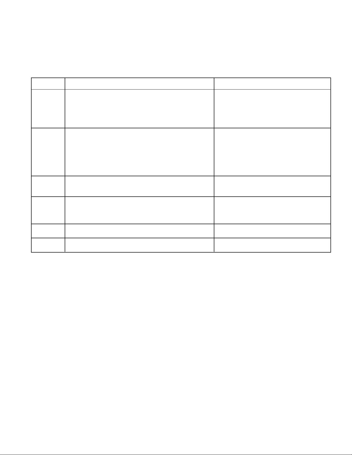
DIAGNOSTICS
Intermittent flashing of the READY indicator indicates that a fault exists. Count the number of flashes between
pauses and use this chart as a guide to investigating the fault.
FLASHES CAUSE THINGS TO CHECK
1 Dry Plug - In Fault - Water Pressure (Is water shut off?)
Sheath of temperature probe dry for 10 minutes after power-up Temperature probe wiring
Fill valve wiring, function, & strainer
Green wire between tank and circuit board
2 Low Tank Level Fault - Water pressure (Is water shut off?)
Level probe dry for 7 minutes after fill valve is energized Shorting pin on J6 connector of control board
not on correct set of pins (See page 7)
Level probe wiring
Temperature probe wiring
Fill valve wiring, function, & strainer
3 Low Water Temperature Fault - Tank heater wiring & function
Sensor in tank is calling for heat for 30 minutes or more Temperature probe wiring
4 Tank Sensor Disagreement - Temperature probe wiring
Level probe detects water, but dry plug-in probe dry Level probe wiring
Green wire between tank and circuit board
5 Temp Sensor Out-of-Range - High Sensor not connected to circuit board
6 Temp Sensor Out-of-Range - Low Sensor wires shorted together or to chassis
Page 13
29460 061599
Page 14

SERVICE
This section provides procedures for testing and
replacing various major components used in this
brewer should service become necessary. Refer to
Troubleshooting
cause of any problem.
WARNING - Inspection, testing, and repair of electrical equipment should be performed only by qualified
service personnel. The brewer should be disconnected
from the power source when servicing, except when
electrical tests are required and the test procedure specifically states to plug-in the brewer.
COMPONENT ACCESS
WARNING - Disconnect the brewer from the power
source before the removal of any panel or the replacement of any component.
All components are accessible by the removal of
the top cover and rear access panel.
for assistance in determining the
The top cover is attached with four #6-32 screws.
Removal of the top cover will allow access to ON/OFF
switch, Start switch, limit thermostat, temperature
probe, control board and tank heater.
The rear access panel is attached with six #8-32
screws. Removal of the rear panel will allow access to
the needle valve.
Page 14
Page 15
SERVICE (cont.)
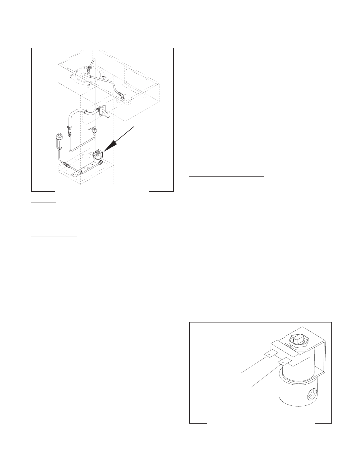
BREW SOLENOID VALVE
P1898.40
FIG. 2 BREW SOLENOID VALVE
Location:
The brew solenoid valve is mounted on the left side
in the bottom rear of the brewer.
Test Procedures:
1. Disconnect the brewer from the power source.
2. Disconnect the white and white/green wires from
the solenoid valve. With the ON/OFF switch in the
"ON" upper position press the start switch.
3. With a voltmeter, check the voltage across the
white and white/green wires. Connect the brewer
to the power source. The indication must be 120
volts ac for two wire 120 volt models.
4. Disconnect the brewer from the power source,
6. Check the solenoid valve for coil action. Connect
the brewer to the power source. With ON/OFF
switch in the "ON" upper position press start switch
and listen carefully in the vicinity of the solenoid
valve for a "clicking" sound as the coil magnet
attracts.
7. Disconnect the brewer from the power source.
If the sound is heard as described and water will not
pass through the solenoid valve, there may be a blockage in the water line before the solenoid valve or, the
solenoid valve may require inspection for wear, and
removal of waterborne particles.
If the sound is not heard as described, replace the
solenoid valve.
Removal and Replacement:
1. Remove all wires from solenoid valve.
2. Turn off the water supply to the brewer.
3. Disconnect the water lines to and from the solenoid valve.
4. Remove the two #8-32 keps nuts holding the
mounting bracket to the brewer base.
5. Lift out the bracket.
6. Remove the two #10-32 slotted-head screws holding the solenoid valve to the mounting bracket.
7. Securely install the new solenoid valve to the
mounting bracket.
8. Attach the mounting bracket to the brewer base.
9. Securely fasten the water lines to and from the
solenoid valve.
10. Refer to Fig. 3 when reconnecting the wires.
If voltage is present as described, proceed to #5
If voltage is not present as described, refer to
Diagrams
and check brewer wiring harness.
Wiring
5. Check for continuity across the solenoid valve coil
terminals.
If continuity is present as described, reconnect the
white and white/green wires to the solenoid valve.
If continuity is not present as described, replace the
solenoid valve.
Page 15
WHI to Power Cord
WHI/GRN to Control
Board J1-4
P1799
FIG.3 SOLENOID VALVE TERMINALS
29460 061599
Page 16
SERVICE (cont.)
LIMIT THERMOSTAT
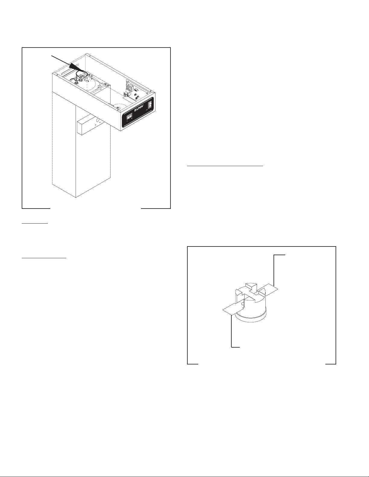
FIG. 4 LIMIT THERMOSTAT
Location:
The limit thermostat is located inside the hood on
the tank lid.
P1798.40
5. With a voltmeter, check the voltage across the exposed terminal of the limit thermostat and the
white wire on the tank heater terminal. Connect
the brewer to the power source. The indication
must be 120 volts ac for two wire 120 volt models.
6. Disconnect the brewer from the power source.
If voltage is present as described, reconnect the black
wire to the limit thermostat. The limit thermostat is
operating properly.
If voltage is not present as described, replace the limit
thermostat.
Removal and Replacement
1. Remove both wires from the limit thermostat terminals.
2. Carefully slide the limit thermostat out from under the retaining clip.
3. Carefully slide the new limit thermostat into the
retaining clip.
4. Refer to Fig. 5 when reconnecting the wires.
Test Procedure:
1. Disconnect the brewer from the power source and
remove the blue wire from the limit thermostat.
2. With a voltmeter, check the voltage across the blue
wire removed from the limit thermostat and the
white wire on the tank heater terminal. Connect
the brewer to the power source. The indication
must be 120 volts ac for two wire120 volt models.
3. Disconnect the brewer to from the power source.
If voltage is present as described, reconnect the blue
wire and proceed to #4.
If voltage is not present as described, refer to the
ing Diagrams
and check the wiring harness.
Wir-
4. Remove the black wire from the limit thermostat.
BLU to Control
Board N.O.
BLK to Tank Heater
FIG. 5 LIMIT THERMOSTAT TERMINALS
P1800
Page 16
29460 061599
Page 17
SERVICE (cont.)
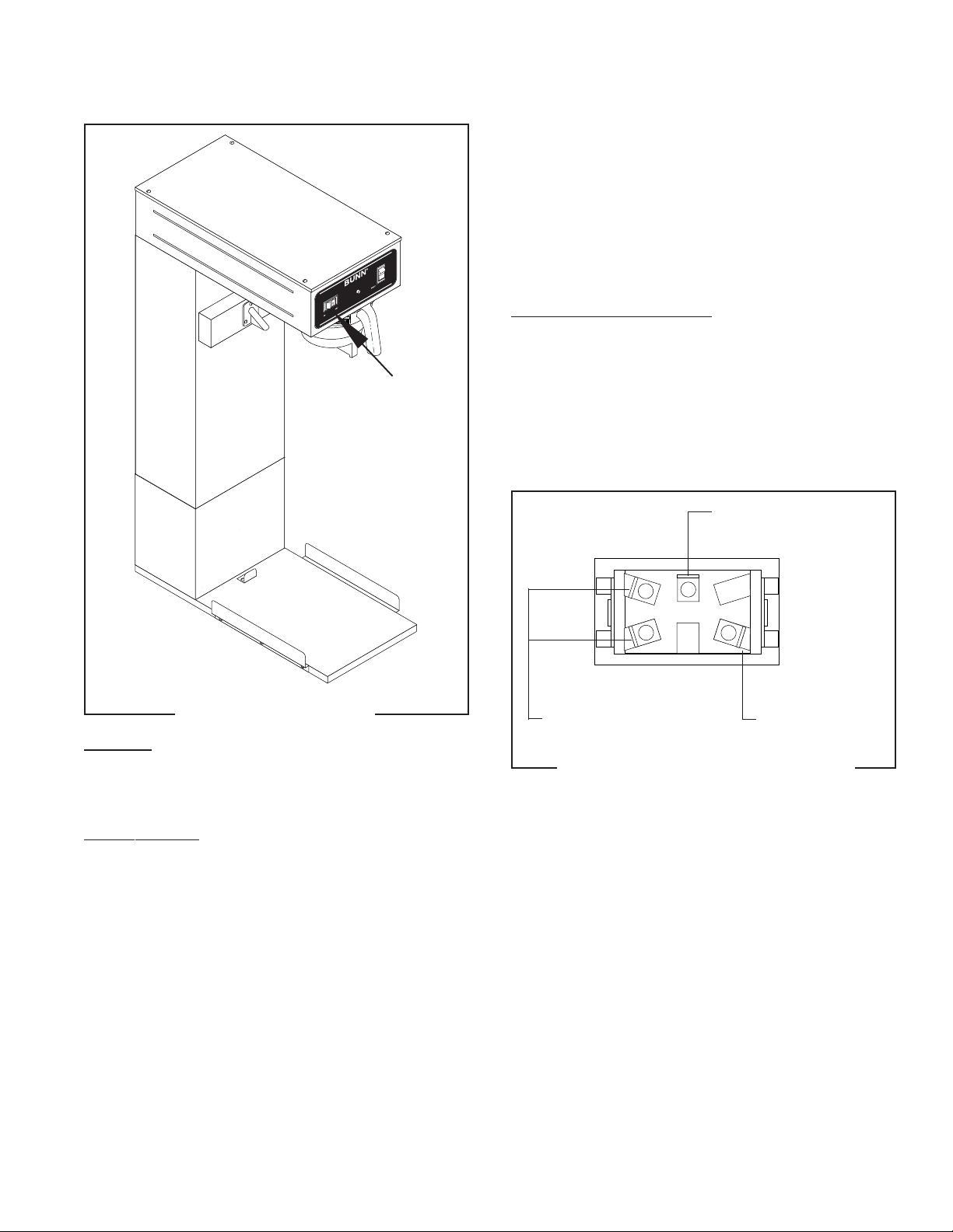
ON/OFF SWITCH
6. Check for continuity across the center and end
terminals of the top row when the switch is in the
“ON” position.
If continuity is present as described, replace the wires,
the switch is operating properly.
If continuity is not present as described, replace the
switch.
Removal and Replacement:
1. Remove the wires from the switch terminals.
2. Compress the clips inside the hood and gently
push the switch through the opening.
3. Push the new switch into the opening and spread
the clips to hold the switch captive in the hood.
4. Refer to FIG. 7 when reconnecting the wires.
BLK to Power Cord
P1187.40
FIG. 6 ON/OFF SWITCH
Location:
The ON/OFF switch is located in the front of the
hood, above and to the left of the brew funnel.
Test Procedure:
1. Disconnect the brewer from the power source.
2. Remove the black and white/violet wires from the
switch terminals.
3. With a voltmeter, check the voltage across the
black wire removed from the ON/OFF switch and
the white wire remaining on the switch terminal.
4. Connect the brewer to the power source. The indication must be 120 volts ac for two wire 120
volt models.
5. Disconnect the brewer from the power source.
If voltage is present as described, proceed to #6.
If voltage is not present as described, refer to the
ing Diagrams
and check the wiring harness.
Wir-
WHI/VIO to
Control Board J1-8
WHI to Power Cord
FIG.7 ON/OFF SWITCH TERMINALS
P1801
Page 17
29460 061599
Page 18
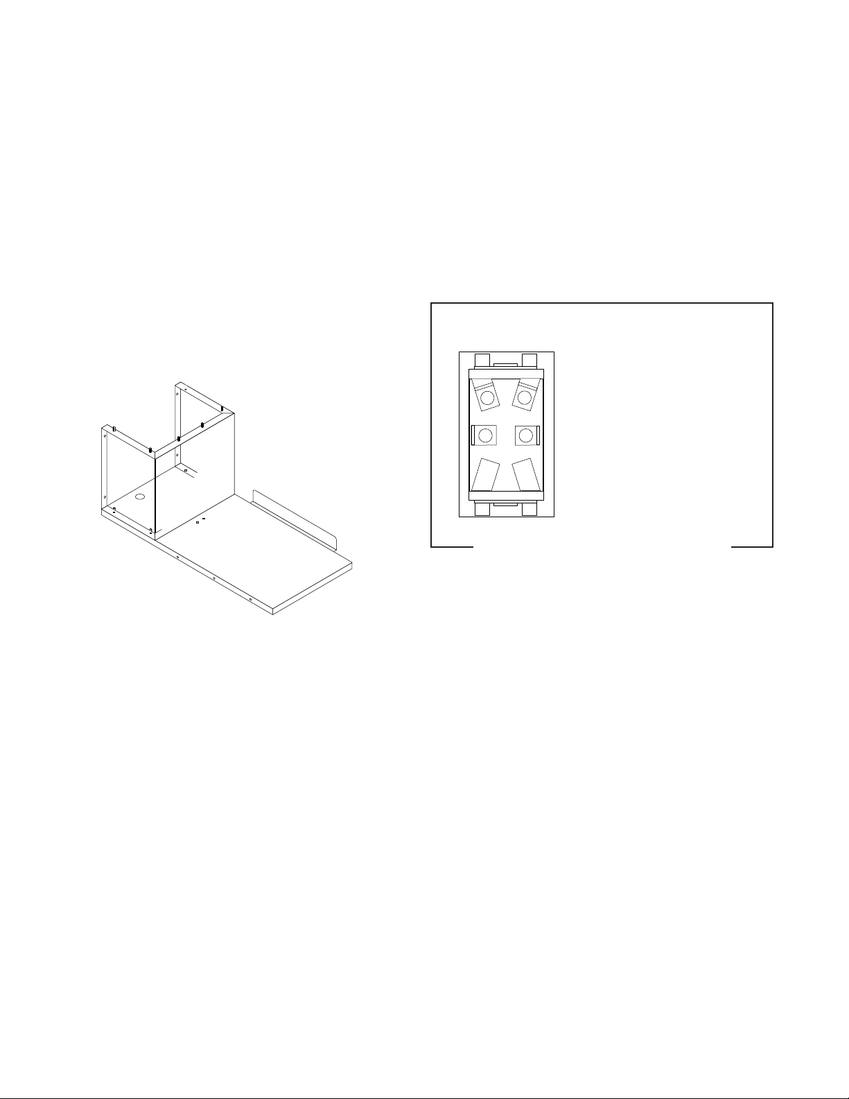
SERVICE (cont.)
START SWITCH
FIG. 9 START SWITCH TERMINALS
P1283
Page 18
Page 19
SERVICE (cont.)
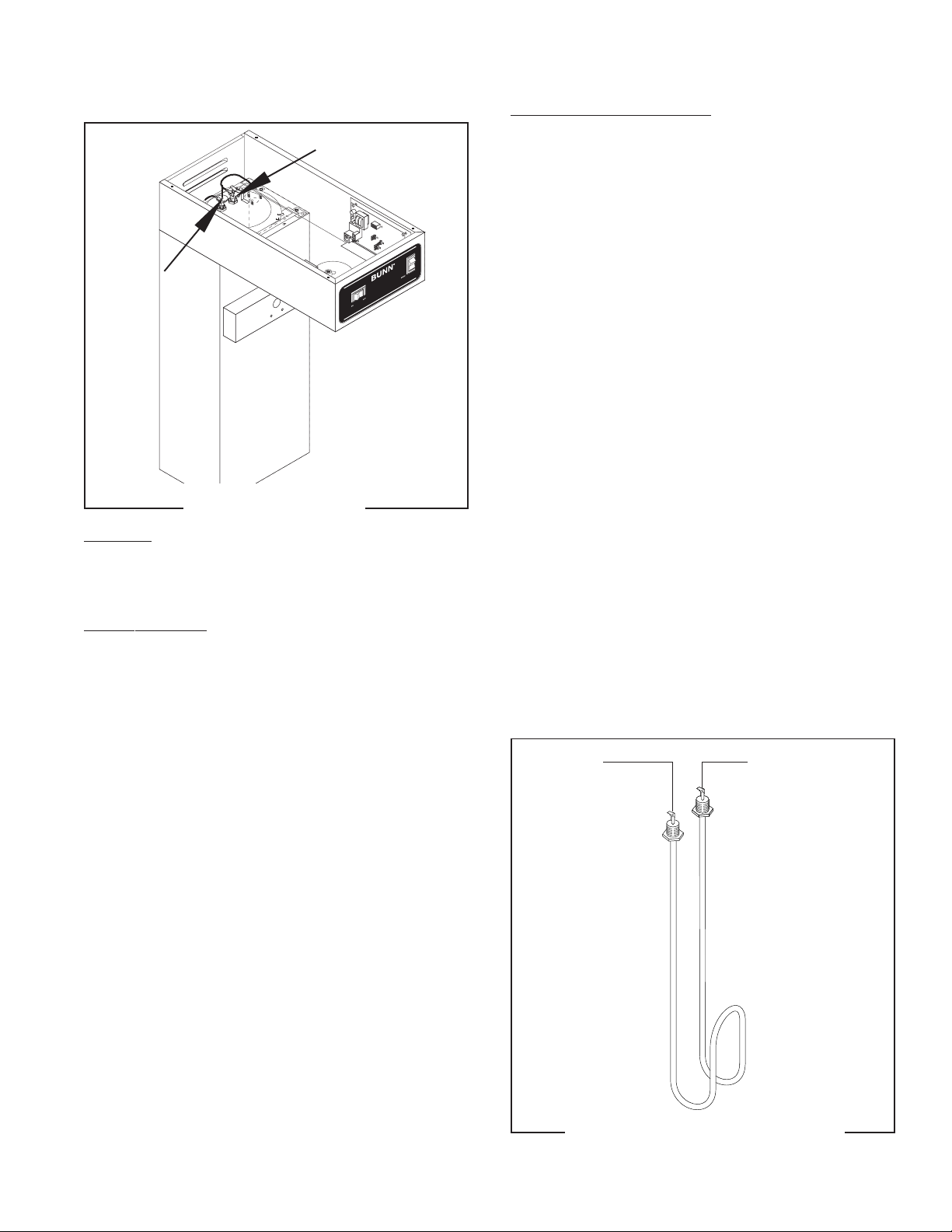
TANK HEATER
P1798.40
FIG. 10 TANK HEATER
Location:
The tank heater is located inside the tank and
secured to the tank lid.
Test Procedures:
1. Disconnect the brewer from the power supply.
2. With a voltmeter, check the voltage across the
black and white wires. Connect the brewer to the
power source. The indication must be 120 volts
ac for two wire 120 volt models .
3. Disconnect the brewer from the power source.
If voltage is present as described, proceed to #4
If voltage is not present as described, refer to the
ing Diagrams
and check wiring harness.
Wir-
Removal and Replacement:
1. Disconnect the black wire and the white wire from
the tank heater terminals.
2. Remove sprayhead and the hex nut securing the
sprayhead tube to the hood. Set aside for reassembly.
3. Disconnect vent tube.
4. Remove the six #10 thread cutting screws securing the tank lid to the tank. Remove the green wire.
5. Remove the tank lid with limit thermostat, spray
head tube, tank heater and vent tube.
6. Remove the two hex nuts securing the tank heater
to the tank lid. Remove tank heater with gaskets
and discard.
7. Install new tank heater with gaskets on the tank
lid and secure with two hex nuts.
8. Install tank lid with limit thermostat, sprayhead
tube, tank heater and vent tube and the green wire
using six #10 thread cutting screws.
9. Secure sprayhead tube to hood using a hex nut.
10. Install sprayhead.
11. Connect vent tube to fitting.
12. Reconnect the wires to the limit thermostat, tank
heater. See
Limit Thermostat
section in this manual
when reconnecting wires.
13. Refer to Fig.11 when reconnecting the tank heater
wires.
WHI to Power CordBLK to Limit
Thermostat
4. Disconnect the black wire and the white wire from
the tank heater terminals.
5. Check for continuity across the tank heater terminals.
If continuity is present as described, reconnect the
wires, the tank heater is operating properly.
If continuity is not present as described, replace the
tank heater.
NOTE- If the tank heater remains unable to heat, re-
move and inspect heater for cracks in the sheath.
Page 19
FIG. 11 TANK HEATER TERMINALS
P1284
29460 061599
Page 20
SERVICE (cont.)
TEMPERATURE PROBE
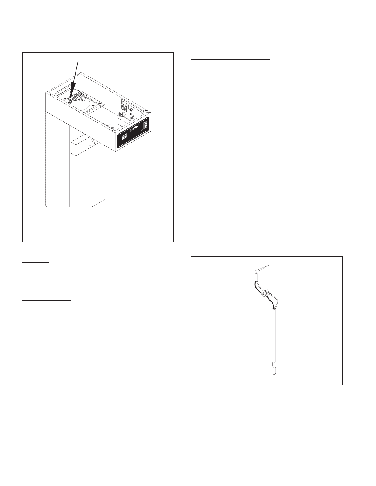
Removal and Replacement:
1. Disconnect the brewer from the power source.
2. Pull the existing probe from the tank lid.
3. Cut the white and black wires close to the probe
and discard the probe. Do not disconnect these
wires from the electronic control assembly.
4. On the new probe, cut the white and black wires
near the terminals. Discard the terminals. Insert
the new probe into the tank assembly.
5. Insert the white wire from the new probe and the
white wire from the electronic control assembly
into one of the UR connectors provided with the
replacement kit, and carefully crimp the connector.
6. Insert the black wire from the new probe and the
black wire from the electronic control assembly
into the remaining UR connector provided with
the replacement kit, and carefully crimp the connector.
7. Refer to Fig. 13 when reconnecting the wires.
FIG. 12 TEMPERATURE PROBE
P1798.40
Location:
The temperature probe is located on the tank rear
of the tank lid, behind the tank heater.
Test Procedures:
1. Disconnect the brewer from the power source.
2. Remove the temperature probe from the grommet.
3. Submerge the probe in a water bath of approximately 70°F (21°C).
4. Connect an ohmmeter to pins 2 and 3 of the J-5
connector on the control board. The indications
should be as follows:
a) 15.3k ± 2k OHMS at 60°F (15°C)
b) 11.8k ± 2k OHMS at 70°F (21°C)
c) 9.3k ± 2k OHMS at 80°F (27°C)
If resistance is present as described, the temperature
probe is operating properly.
If resistance is not present as described, replace the
temperature probe.
To Control Board J-5,
Pins 2 & 3
P2225
FIG. 13 TEMPERATURE PROBE TERMINALS
Page 20
29460 082300
Page 21
SERVICE (cont.)
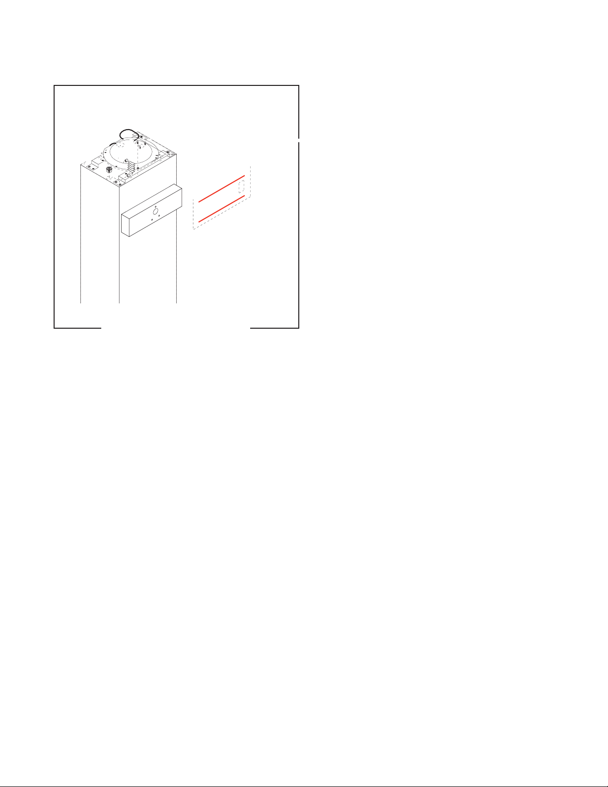
CONTROL BOARD
FIG. 14 CONTROL BOARD
P1798.40
Page 21
Page 22
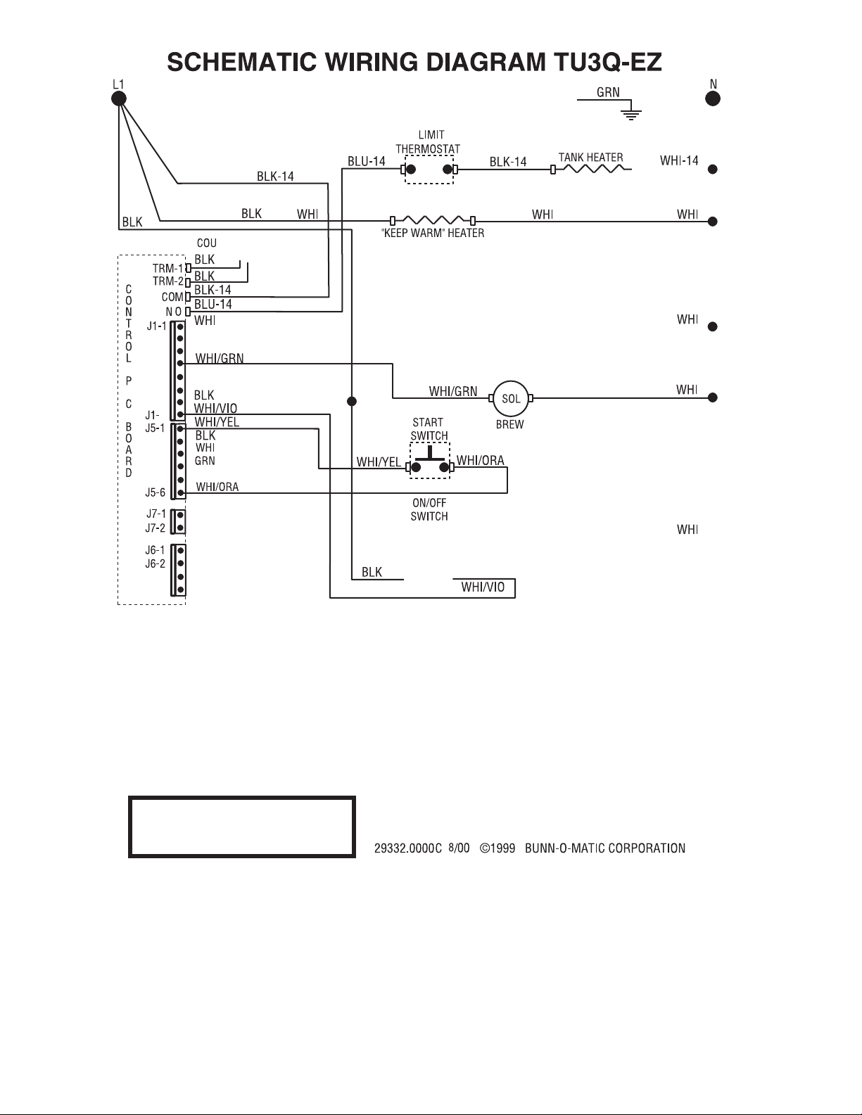
Page 22
 Loading...