

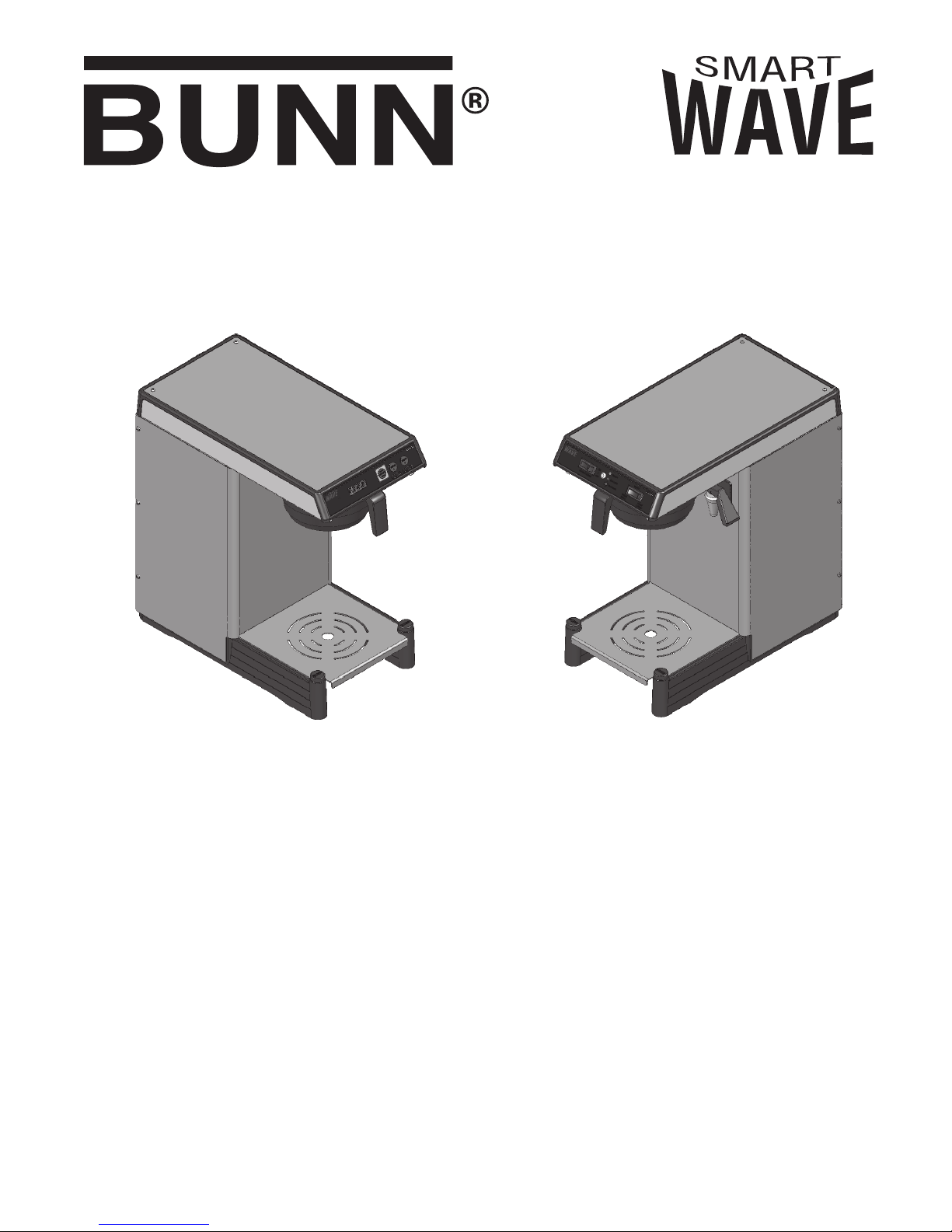
Bunn SmartWave APS, Smart Wave Series, Smart Wave Silver Series Installation And Operating Manual
Page 1
Series
Smart Wave Series Smart Wave Silver Series
T
M
TM
TM
INSTALLATION & OPERATING MANUAL
BUNN-O-MATIC CORPORATION
SPRINGFIELD, ILLINOIS 62708-3227
PHONE: (217) 529-6601 FAX: (217) 529-6644
To ensure you have the latest revision of the manual or to obtain the illustrated parts catalog, please visit the Bunn-O-Matic
website, at www.bunn.com. This is absolutely FREE, and the quickest way to obtain the latest catalog and manual updates.
Contact Bunn-O-Matic Corporation at 1-800-286-6070 to obtain a paper copy of the required Illustrated Parts Catalog
mailed via U.S. Postal Service.
40410.0000A 09/07 ©2007 Bunn-O-Matic Corporation www.bunn.com
POST OFFICE BOX 3227
Page 2

BUNN-O-MATIC COMMERCIAL PRODUCT WARRANTY
Bunn-O-Matic Corp. (“BUNN”) warrants equipment manufactured by it as follows:
1) All equipment other than as specifi ed below: 2 years parts and 1 year labor.
2) Electronic circuit and/or control boards: parts and labor for 3 years.
3) Compressors on refrigeration equipment: 5 years parts and 1 year labor.
4) Grinding burrs on coffee grinding equipment to grind coffee to meet original factory screen sieve analysis:
parts and labor for 3 years or 30,000 pounds of coffee, whichever comes fi rst.
These warranty periods run from the date of installation BUNN warrants that the equipment manufactured by
it will be commercially free of defects in material and workmanship existing at the time of manufacture and
appearing within the applicable warranty period. This warranty does not apply to any equipment, component or
part that was not manufactured by BUNN or that, in BUNN’s judgment, has been affected by misuse, neglect,
alteration, improper installation or operation, improper maintenance or repair, damage or casualty. This warranty is
conditioned on the Buyer 1) giving BUNN prompt notice of any claim to be made under this warranty by telephone
at (217) 529-6601 or by writing to Post Offi ce Box 3227, Springfi eld, Illinois 62708-3227; 2) if requested by
BUNN, shipping the defective equipment prepaid to an authorized BUNN service location; and 3) receiving prior
authorization from BUNN that the defective equipment is under warranty.
THE FOREGOING WARRANTY IS EXCLUSIVE AND IS IN LIEU OF ANY OTHER WARRANTY, WRITTEN OR
ORAL, EXPRESS OR IMPLIED, INCLUDING, BUT NOT LIMITED TO, ANY IMPLIED WARRANTY OF EITHER
MERCHANTABILITY OR FITNESS FOR A PARTICULAR PURPOSE. The agents, dealers or employees of BUNN
are not authorized to make modifi cations to this warranty or to make additional warranties that are binding on
BUNN. Accordingly, statements by such individuals, whether oral or written, do not constitute warranties and
should not be relied upon.
If BUNN determines in its sole discretion that the equipment does not conform to the warranty, BUNN, at its
exclusive option while the equipment is under warranty, shall either 1) provide at no charge replacement parts
and/or labor (during the applicable parts and labor warranty periods specifi ed above) to repair the defective
components, provided that this repair is done by a BUNN Authorized Service Representative; or 2) shall replace
the equipment or refund the purchase price for the equipment.
THE BUYER’S REMEDY AGAINST BUNN FOR THE BREACH OF ANY OBLIGATION ARISING OUT OF THE SALE OF
THIS EQUIPMENT, WHETHER DERIVED FROM WARRANTY OR OTHERWISE, SHALL BE LIMITED, AT BUNN’S
SOLE OPTION AS SPECIFIED HEREIN, TO REPAIR, REPLACEMENT OR REFUND.
In no event shall BUNN be liable for any other damage or loss, including, but not limited to, lost profi ts, lost sales,
loss of use of equipment, claims of Buyer’s customers, cost of capital, cost of down time, cost of substitute
equipment, facilities or services, or any other special, incidental or consequential damages.
BrewWISE, BUNN Gourmet Ice, BUNN Pour-O-Matic, BUNN, Bunn-OMatic, Bunn-O-Matic, BUNNserve, BUNN Espress,
DBC, Dr. Brew, Dual, EasyClear, Easy Pour, FlavorGard, Gourmet Ice, Gourmet Juice, High Intensity, IMIX, Infusion Series, Legendary for Quality, The Mark of Quality in Beverage Equipment Worldwide, My Café, PowerLogic, Safety-Fresh,
Single, Smart Funnel, Smart Hopper, Soft Heat, SplashGard, System III, ThermoFresh, AXIOM, Beverage Profi t Calculator,
Beverage Bar Creator, BrewLOGIC, BrewMETER, BrewWIZARD, BUNNlink, BUNNSERVE, BUNNsource, Coffee At Its Best,
Coffee Spot, Cool Froth, Digital Brewer Control, Earth-1st, Earth 1st, Earth First, EasyGard, Intellisteam, Nothing Brews
Like a BUNN, Pouring Profi ts, Pulse Wave, Quality Beverage Equipment Worldwide, Scale-Pro, Signature Series, Silver
Series, Smart Heat, SmartWAVE, Tea At Its Best, The Horizontal Red Line, Titan, Ultra, are either trademarks or registered
trademarks of Bunn-O-Matic Corporation.
Page 2
40410 100407
Page 3
CONTENTS
Warranty .............................................................................................................2
Introduction ........................................................................................................3
User Notices .......................................................................................................3
Electrical Requirements ......................................................................................4
Plumbing Requirements .....................................................................................5
Initial Setup .........................................................................................................6
Brewing ...............................................................................................................7
Operating Controls/ Programming ......................................................................8
Deliming ............................................................................................................12
Cleaning ............................................................................................................13
Cover Removal ..................................................................................................14
Draining Tank ....................................................................................................15
Switch Settings .................................................................................................16
Troubleshooting ................................................................................................17
Schematic Wiring Diagrams ..............................................................................18
INTRODUCTION
This equipment is factory set to brew approximately 64 ounces of coffee into an awaiting dispenser. It is only
for indoor use on a sturdy counter or shelf.
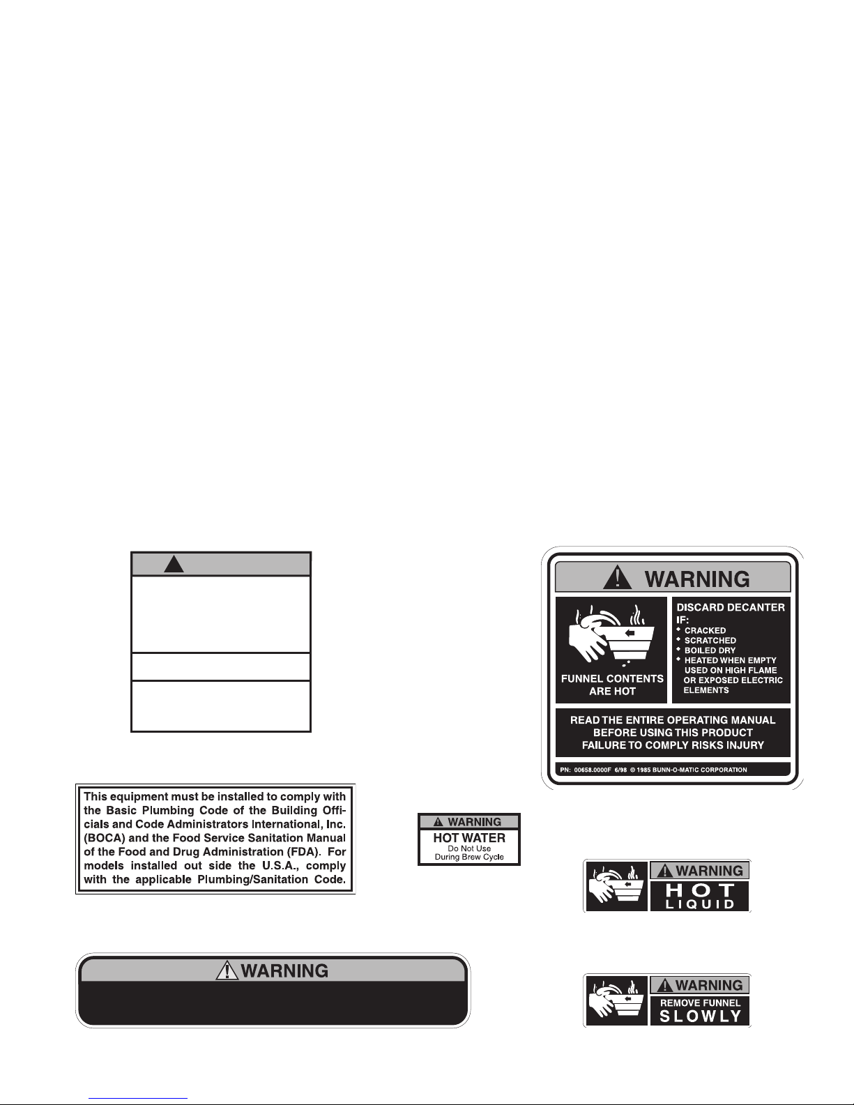
! WARNING
DO NOT OVERLOAD CIRCUIT.
ALWAYS ELECTRICALLY GROUND
THE CHASSIS OR ADAPTOR PLUG.
DO NOT DEFORM PLUG OR CORD.
FOLLOW NATIONAL AND LOCAL
ELECTRICAL CODES.
KEEP COMBUSTIBLES AWAY.
FAILURE TO COMPLY RISKS EQUIPMENT
DAMAGE, FIRE OR SHOCK HAZARD.
READ THE ENTIRE
OPERATING MANUAL BEFORE
USING THIS PRODUCT
00986.0000E 5/98 ©1994 Bunn-O-Matic Corporation
#00986.0000
#00656.0000
USER NOTICES
#00658.0000
#00882.0000
#03409.0002
To reduce the risk of electric shock,
do not remove or open cover.
No user-serviceable parts inside.
#37881.0002
Authorized service personnel only.
Disconnect power before servicing.
Page 3
#03408.0002
40410 092407
Page 4
ELECTRICAL REQUIREMENTS
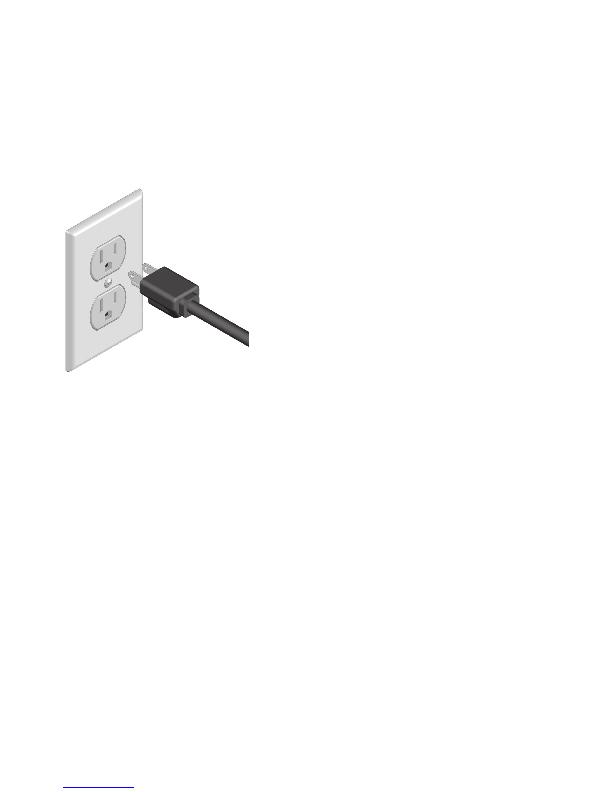
CAUTION - The brewer must be disconnected from the power source until specifi ed in Initial Set-Up.
All 120V models have an attached cordset and plug.
Model 15 requires 2-wire grounded service rated 120 volts ac, 15 amp, single phase, 60 Hz.
Model 35 requires 3-wire, grounded service rated 220-240 volts ac, 10 amp, single phase, 50/60 Hz.
L2 RED L2 RED
WHITE
NEUTRAL
L1 BLACK
GREEN GREEN
WHITE
NEUTRAL
L1 BLACK
L2
120V. A.C.
N
120V. A.C.
L1
G
208 or 240V. A.C.
FIG 1 FIG 2
Model 15 has an attached cordset and requires
2-wire grounded service rated 120 volts ac, 15 amp,
single phase, 60 Hz.
Model 35 requires 3-wire, grounded service rated
120/208 or 120/240 volts ac, 20 amp, single phase, 60
Hz. Proceed as follows:
Electrical Hook-Up
CAUTION – Improper electrical installation will damage electronic components.
1. An electrician must provide electrical service as specifi ed.
2. Using a voltmeter, check the voltage and color coding of each conductor at the electrical source.
3. If plumbing is to be hooked up later be sure the brewer is disconnected from the power source. If plumbing
has been hooked up, the brewer is ready for Initial Set-Up.
Electrical Hook-Up
CAUTION – Improper electrical installation will damage electronic components.
1. An electrician must provide electrical service as specifi ed.
2. Using a voltmeter, check the voltage and color coding of each conductor at the electrical source.
3. Remove the front panel beneath the sprayhead.
4. Feed the cord through the strain relief and connect it to the terminal block.
5. Connect the brewer to the power source and verify the voltage at the terminal block before proceeding.
Replace the front panel.
6. If plumbing is to be hooked up later be sure the brewer is disconnected from the power source. If plumbing
has been hooked up, the brewer is ready for Initial Set-Up.
Page 4
40410 092407
Page 5
PLUMBING REQUIREMENTS
These brewers must be connected to a cold water system with operating pressure between 20 and 90 psi
1
(138 and 620 kPa) from a
brewer. Install a regulator in the line when pressure is greater than 90 psi (620 kPa) to reduce it to 50 psi (345
kPa). The water inlet fi tting is
deionized water supply to this equipment.
NOTE - Bunn-O-Matic recommends
25 feet from the 1⁄2" water supply line. A tight coil of tubing in the water line will facilitate moving the brewer to
clean the countertop. Bunn-O-Matic does not recommend the use of a saddle valve to install the brewer. The
size and shape of the hole made in the supply line by this type of device may restrict water fl ow.
This equipment must be installed to comply with the Basic Plumbing Code of the
Building Offi cials and Code Administrators International, Inc. (BOCA)
and the Food Service Sanitation Manual of the Food and Drug Administration (FDA).
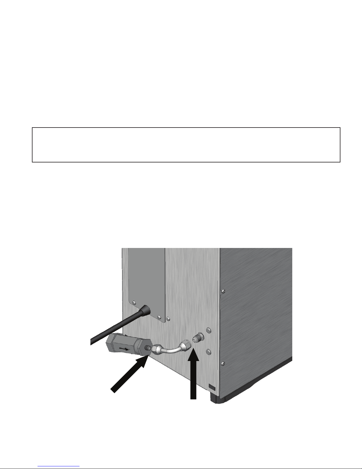
Plumbing Hook-Up
1. Flush the water line.
2. Securely attach the Strainer/Flow Control and tube assembly to the water supply line.
3. Securely attach tube assembly to the fl are fi tting at the rear of the brewer.
4. Turn on the water supply.
⁄2" or larger supply line. A shut-off valve should be installed in the line before the
1
⁄4" fl are. Bunn-O-Matic does not recommend the use of a reverse-osmosis or
1
⁄4" copper tubing for installations of less than 25 feet and 3⁄8" for more than
Page 5
FIG 3
40410 092407
Page 6
INITIAL SET UP
CAUTION - The brewer must be disconnected from the power source throughout the initial set-up, except when
specifi ed in the instructions.
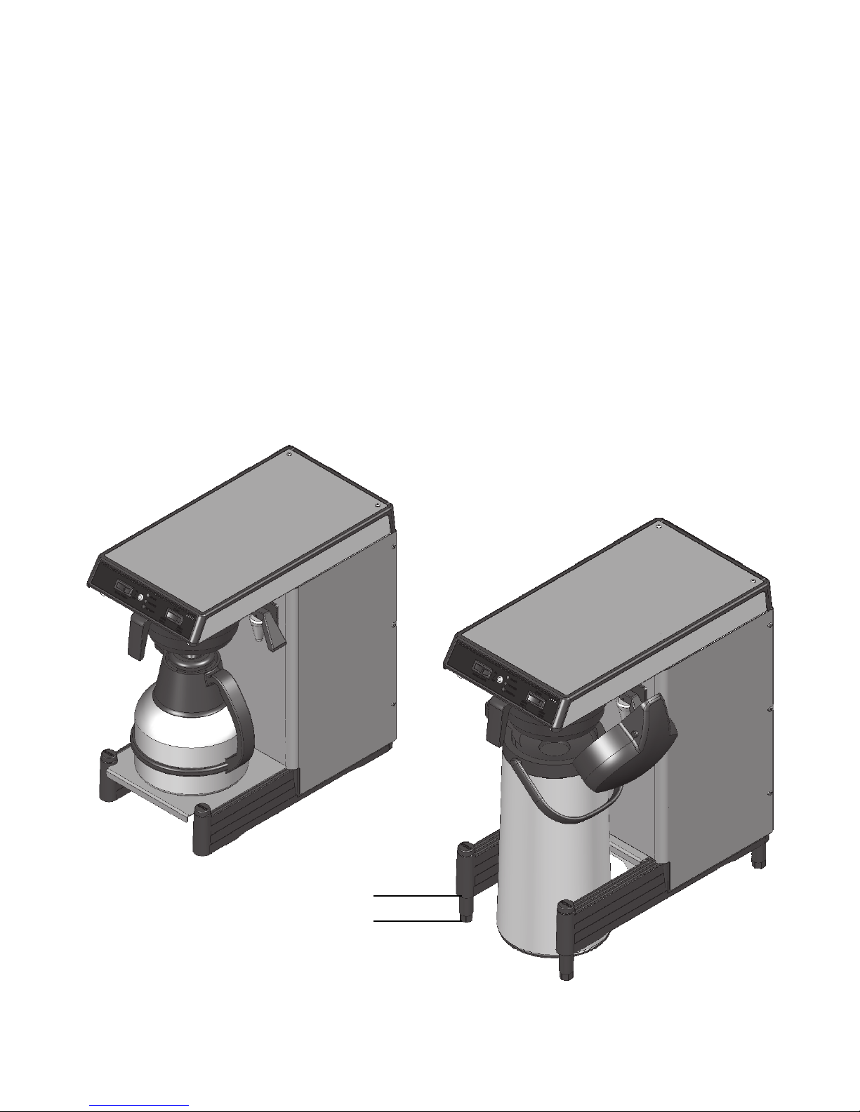
1. Insert an empty funnel into the funnel rails. (FIG 4)
2. Place an empty server under the funnel. For taller servers, lift up on the front of the booster plate, and slide
it back into the trunk housing.
NOTE: If more height is need, the legs may be extended to a maximum of 1¾˝. (FIG 5)
3. Connect the brewer to the power source.
4. Press and release the "ENABLE BREW ON/OFF" switch. (Indicator/Display must be lit!). Water will fl ow into
the tank and stop when the tank is fi lled to its capacity.
5. Wait approximately twenty minutes for the water in the tank to heat to the proper temperature. Display will
show "READY" (green light on Silver Series) when tank is at operating temperature. Some water will drip
from the funnel during this time; this is due to expansion and is normal part of setup.
6. Water volumes and fl ow settings have been preset at the factory. Refer to Adjustments Section of this manual
to set brew volumes should the volume need to be increased or decreased.
7. The brewer is now ready for use in accordance with the instructions for Coffee Brewing.
FIG 4
1¾˝ Max.
Page 6
FIG 5
40410 092407
Page 7
COFFEE BREWING
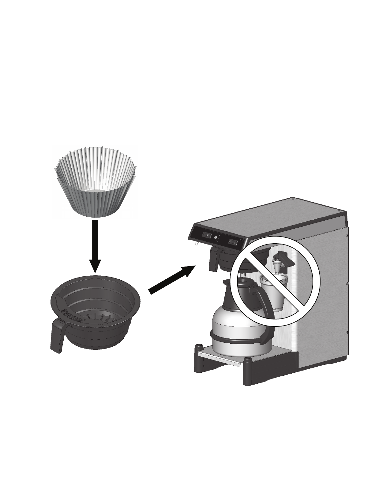
1. Begin each brew cycle with a clean empty brew funnel.
2. Insert a BUNN fi lter into the funnel. (FIG 6)
3. Pour (or grind) fresh coffee into the fi lter and level the bed of grounds by gently shaking.
4. Slide the funnel into the funnel rails until it stops.
5. Place an empty server under the funnel.
6. Verify that the "ENABLE BREW ON/OFF" switch is on.
7. Momentarily press and release the desired "BREW" switch. The display will read "BREWING" (fl ashing red
light on Silver Series).
8. After the coffee fi nishes dripping from the funnel tip, carefully remove the brew funnel and discard the grounds
and fi lter. Rinse funnel.
DO NOT USE FAUCET DURING BREW CYCLE!
FIG 6
FIG 6A
Page 7
40410 092407
Page 8
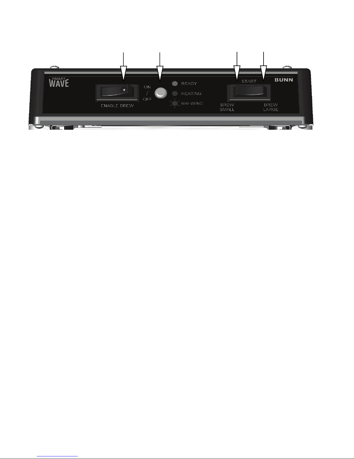
OPERATING CONTROLS - SILVER SERIES
A D
TM
BC
FIG 7
Smart Wave Silver Series
(A) ENABLE BREW ON/OFF SWITCH
Pressing the "ENABLE BREW ON/OFF" switch (indicator on) enables the brew circuit, and energizes the tank refi ll
circuit. Pressing the switch again (indicator off) stops tank refi lling and brewing. Stopping a brew cycle after
it has been started will not stop the fl ow of water into the server until the funnel is empty.
NOTE 1: – Stopping a brew cycle by pressing the "ENABLE BREW ON/OFF" switch to the "OFF" position, will disable the tank refi ll circuit. If the level is low enough, tank heating may be disabled as well. Simply pressing the
"ENABLE BREW ON/OFF" switch to the "ON" position will allow the tank to replenish. Allow a few minutes for the
tank to heat back up to it's ready temperature.
NOTE 2: – Hot water will be available at the faucet in a limited amount when the "ENABLE BREW ON/OFF" switch
is in the "OFF" position because the tank will not refi ll. Refer to NOTE 1 regarding low level.
(B) SMALL BREW SWITCH
Momentarily pressing and releasing the switch starts the selected "SMALL" brew cycle when the "ENABLE BREW
ON/OFF" indicator is on. (Factory set for approx. 64 ounces)
(C) LARGE BREW SWITCH
Momentarily pressing and releasing the switch starts the selected "LARGE" brew cycle when the "ENABLE BREW
ON/OFF" indicator is on. (Factory set for approx. 64 ounces)
(D) STATUS INDICATOR
Steady green - ready to brew.
Steady red - tank is heating up.
Flashing red - brew cycle in process.
Page 8
40410 092407
Page 9

PROGRAMMING - SILVER SERIES
BREW VOLUME SET-UP:
NOTE: Set small and large batches separately. Maximum water on time is 5 minutes.
Use the following steps when the setting is unknown.
1. Place an empty funnel in the funnel rails and an empty server beneath the funnel.
2. Press the "ENABLE BREW ON/OFF" switch ("ON").
3. Press and hold the small brew start switch until the LED indicator alternately fl ashes red/green (approximately
15 seconds). Release the switch.
4. Allow the cycle to continue until the desired amount of water is dispensed and then press the "ENABLE BREW
ON/OFF" to turn "OFF" the brewer.
The brewer is now set to dispense this amount of water for each subsequent small brew cycle.
To increase the amount of water for each brew cycle place an empty funnel in the funnel rails and an empty
server beneath the funnel. Press the "ENABLE BREW ON/OFF" switch (ON). Press and hold the small "BREW"
switch until you hear the solenoid click on-and-off three times (approximately 10 seconds), then release the small
"BREW" switch. Momentarily press and release the small "BREW" switch once for each ounce (approximate) of
water to be added to the prior setting and allow the brew cycle to fi nish.
To decrease the amount of water for each brew cycle place an empty funnel in the funnel rails and an empty
server beneath the funnel. Press the "ON/OFF" switch (ON). Momentarily press and release the small "BREW"
switch once for each ounce (approximate) of water to be removed from the existing setting. Press and hold the
small "BREW" switch until you hear the solenoid click on-and-off three times (approximately 10 seconds), then
release the small "BREW" switch and allow the cycle to fi nish.
NOTE: Repeat the steps above to set the large batch by using the large brew switch as desired.
OPTIONAL PULSE BREW SET-UP:
NOTE: Set small and large batches separately. Brewer has 4 preset pulse brew routines to choose from.
Factory default is 1. With 4 being the maximum time.
With the machine off, press the small or large switch for 10 seconds. Red LED will fl ash to indicate current setting
( 1 – 4 ). Press same switch the number of times ( 1 – 4 ) for the desired setting. If the switch is pressed more
than 4 times, the setting will remain at 4. After 5 seconds the red Led will resume fl ashing the selected number.
When no switches are pressed for 30 seconds, the mode will exit. Or the mode may be exited by pressing the
"ENABLE BREW ON/OFF" switch. Repeat above procedure with the other brew switch.
Restore Factory Defaults:
Press the "ENABLE BREW ON/OFF" switch while applying AC power. Continue pressing the "ENABLE BREW ON/
OFF" switch for 10 seconds. During that 10 seconds, the red LED will be on steady. After 10 seconds the green
LED will begin fl ashing rapidly for 5 seconds. During that 5 seconds, release and again momentarily press the
"ENABLE BREW ON/OFF" switch again to restore default settings. The Led will alternate rapidly Red and Green
for a few seconds indicating the restore has been accomplished.
Note: The Restore process cannot be done when Dip Switch # 1 is On (Program Lockout)
Page 9
40410 092407
Page 10
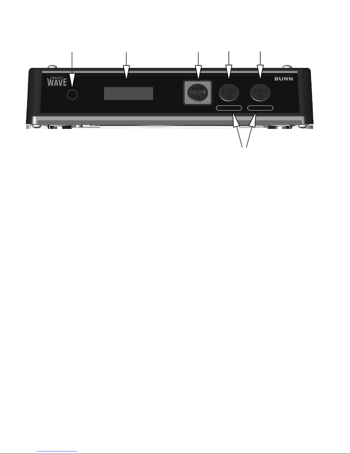
OPERATING CONTROLS - SMART WAVE WITH DISPLAY
D
TM
E
A
BC
FIG 8
Smart Wave Series
F
(A) ENABLE BREW ON/OFF SWITCH
Pressing the "ENABLE BREW ON/OFF" switch (indicator/display on) enables the brew circuit, and the tank refi ll
circuit. Pressing the switch again (indicator/display off) stops tank refi lling and brewing. Stopping a brew cycle
after it has been started will not stop the fl ow of water into the server until the funnel is empty.
NOTE 1: – Stopping a brew cycle by pressing the "ENABLE BREW ON/OFF" switch to the "OFF" position, will disable the tank refi ll circuit. If the level is low enough, tank heating may be disabled as well. Simply pressing the
"ENABLE BREW ON/OFF" switch to the "ON" position will allow the tank to replenish. Allow a few minutes for the
tank to heat back up to it's ready temperature.
NOTE 2: – Hot water will be available at the faucet in a limited amount when the "ENABLE BREW ON/OFF" switch
is in the "OFF" position because the tank will not refi ll. Refer to NOTE 1 regarding low level.
(B) BREW A SWITCH (-)
Momentarily pressing and releasing the switch starts the selected "A" brew cycle when the "ENABLE BREW ON/
OFF" indicator is on. (Factory set for approx. 64 ounces)
(C) BREW B SWITCH (+)
Momentarily pressing and releasing the switch starts the selected "B" brew cycle when the "ENABLE BREW ON/
OFF" indicator is on. (Factory set for approx. 64 ounces)
(D) HIDDEN PROGRAM SWITCH (Enter)
(E) STATUS DISPLAY
Indicates tank ready, brew cycle, and drip out cycle.
(F) BATCH SIZE/FLAVOR LABELS
Included
Page 10
40410 092407
Page 11

PROGRAMMING - SMART WAVE WITH DISPLAY
BREW VOLUME SET-UP:
NOTE: Maximum water on time is 5 minutes.
1. Press the "HIDDEN" switch until display reads A1. This represents the adjust mode "Brew Time" for the "A"
brew switch. The display will then change to (minutes-seconds). Press "BREW A" to decrease time (-) or
"BREW B" to increase time (+).
2. Press and release "HIDDEN" switch until display reads A2. This represents the adjust mode "Brew Meter"
(Pulse Brew) for the "A" brew switch. The display will then change to (1-14). Brewer has 14 preset pulse brew
routines to choose from. Factory default is 1. With 14 being the maximum time. Press "BREW A" to decrease
(-) or "BREW B" to increase (+).
3. Press and release "HIDDEN" switch until display reads A3. This represents the adjust mode "Drip Out Time"
for the "A" brew switch. The display will then change to (minutes-seconds). Press "BREW A" to decrease time
(-) or "BREW B" to increase time (+).
4. Repeat steps 1 -3 for setting the "B" brew switch.
A1 = Brew switch "A" Brew time
A2 = Brew switch "A" Brew meter
A3 = Brew switch "A" Drip out time
B1 = Brew switch "B" Brew time
B2 = Brew switch "B" Brew meter
B3 = Brew switch "B" Drip out time
Restore Factory Defaults:
Press the "ENABLE BREW ON/OFF" switch while applying AC power. Continue pressing the "ENABLE BREW ON/
OFF" switch for 10 seconds. During that 10 seconds the middle bars on the display will be on. After 10 Seconds
the the 3 upper, middle and lower bars on the display will be lit for 5 seconds. During that 5 seconds, release and
again press the "ENABLE BREW ON/OFF" switch to restore default settings – the display will show “DONE”.
Note: The Restore process cannot be done when Dip Switch # 1 is On (Program Lockout)
Page 11
40410 092407
Page 12
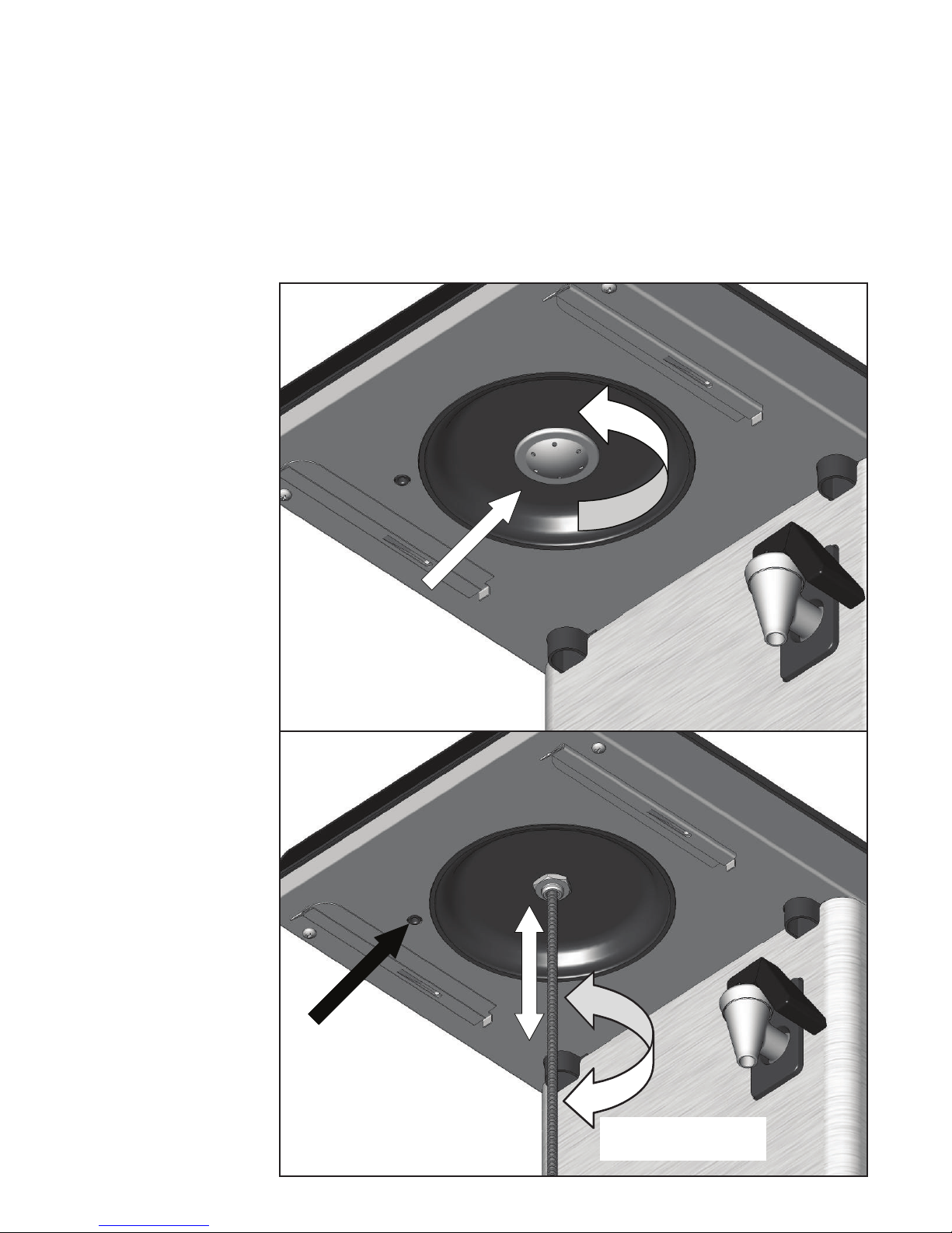
DELIMING
Bunn-O-Matic recommends deliming your coffee brewer periodically. The actual frequency of deliming depends on the mineral content of the water you use. NOTE: In hard water areas, this may need to be done daily.
It will help prevent liming problems in the brewer and takes less than a minute.
Follow these simple steps:
1. Unplug the brewer and
let it cool down before
proceeding.
2. Remove the brew funnel.
3. Remove the sprayhead by
turning it to the left with
your fi ngertips and set it
aside.
4. With the sprayhead
removed, insert the
deliming spring (provided) all the way into the
sprayhead tube. When
inserted properly, no
more than two inches of
spring should be visible.
Saw back and forth fi ve
or six times. Remove the
spring.
5. Check the holes in the
sprayhead. If plugged by
lime, they may be cleared
using a toothpick. Rinse
the sprayhead with water
before reinstalling it.
6. Reinstall the sprayhead
by turning it to the right.
7. Plug in the brewer and
allow the water to reheat
before using.
Remove sprayhead by
turning counterclockwise
FIG 9
Keep vent hole
clear of debris
FIG 10
Page 12
Twist deliming spring
while pushing in
40410 092407
Page 13
CLEANING
The use of a damp cloth rinsed in any mild, non-abrasive, liquid detergent is recommended for cleaning all
surfaces on Bunn-O-Matic equipment.
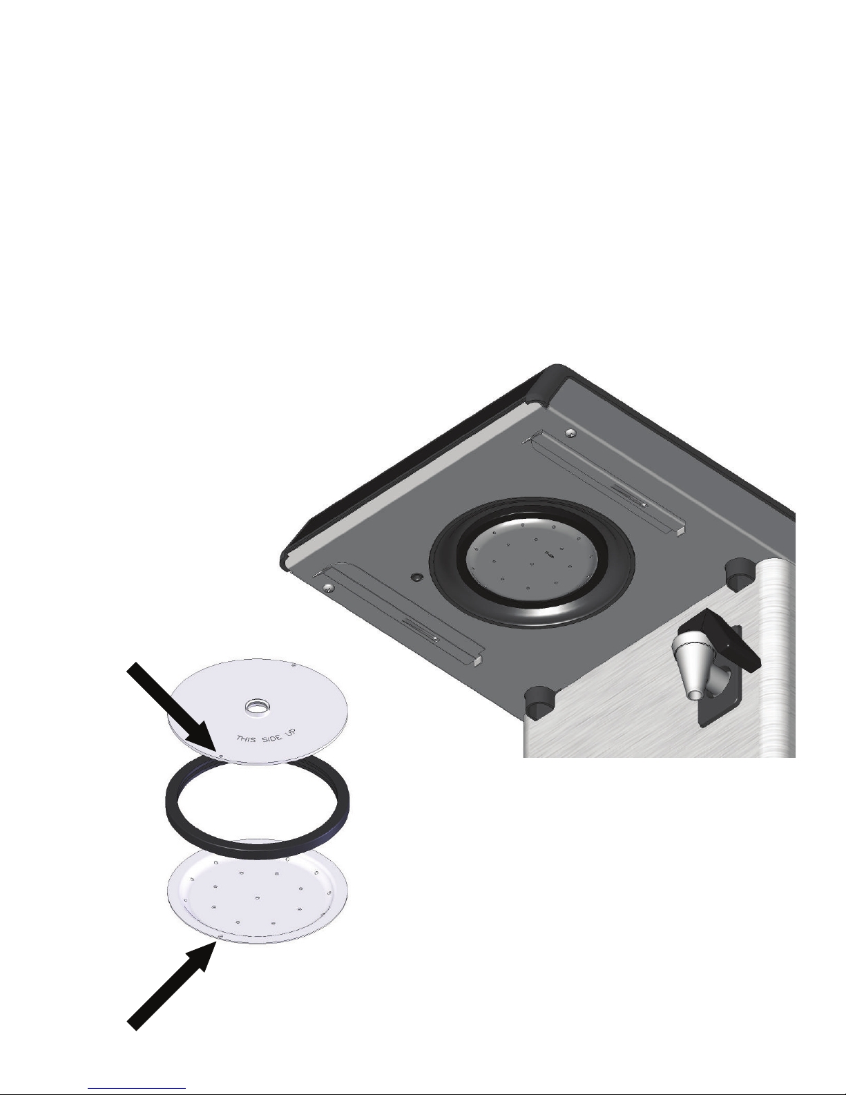
CLEANING OPTIONAL LARGE SPRAYHEAD
1. Remove the brew funnel.
2. Remove the sprayhead by turning it counterclockwise with your fi ngertips.
3. Disassemble sprayhead by removing rubber gasket.
4. Check the holes in the sprayhead. If plugged by lime, they may be cleared using a toothpick. Rinse the
sprayhead with water.
5. Reassemble the sprayhead according to FIG 11. NOTE: Verify the indents are aligned. (ARROWS)
6. Reinstall the sprayhead by turning it clockwise. Hand tighten only!
FIG 11
Page 13
FIG 12
40410 092407
Page 14
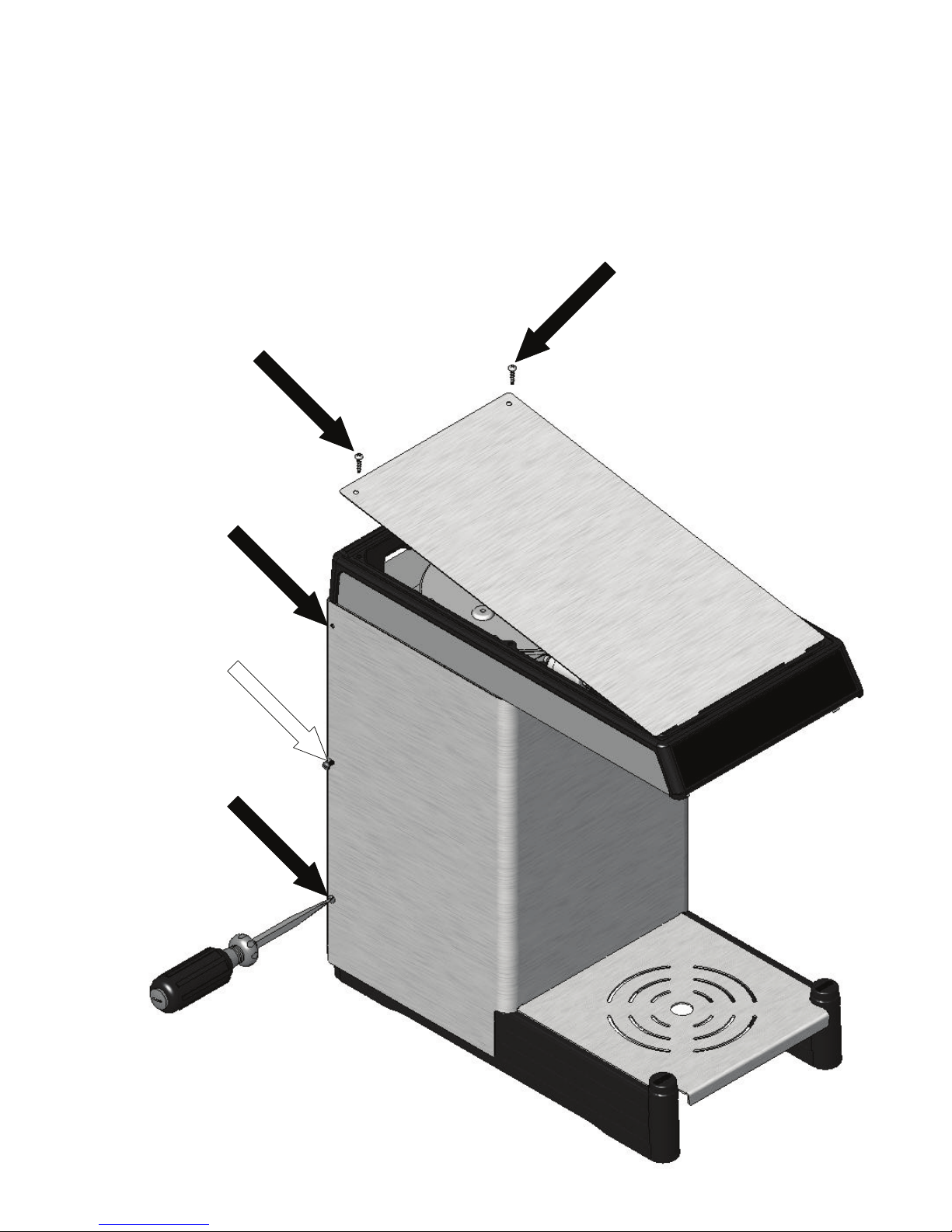
COVER REMOVAL
Unplug the brewer and let it cool down before proceeding.
Front Wrap:
1. Remove the brew funnel.
2. Remove upper and lower screws on either side of front cover.
3. Loosen middle screw on either side of front cover.
4. Pull front cover towards front of brewer.
Top Cover:
1. Remove both screws.
2. Lift top cover to clear front tabs.
REMOVE
REMOVE
REMOVE
LOOSEN
REMOVE
FIG 13
Page 14
40410 092407
Page 15
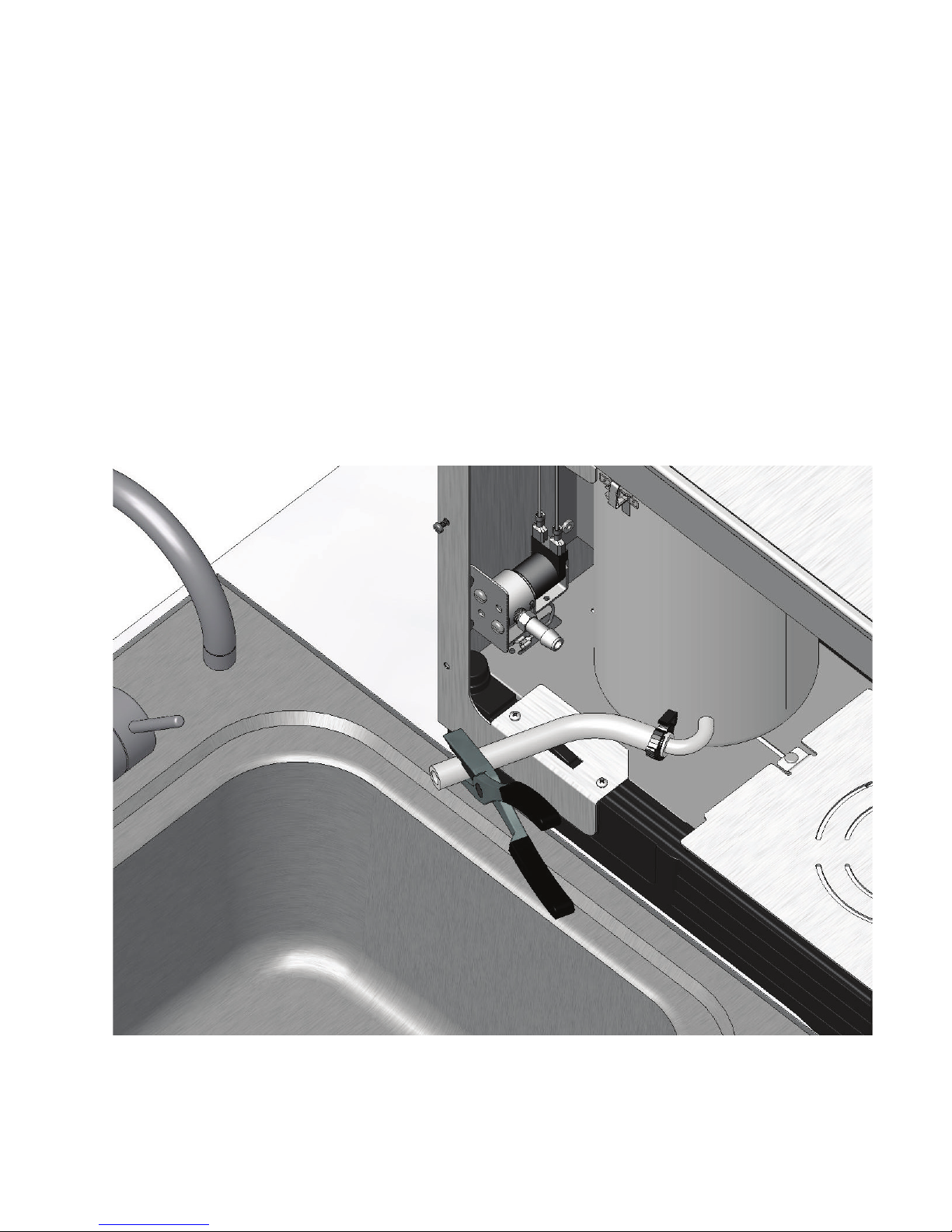
DRAINING TANK
1. Unplug the brewer and let it cool down before proceeding.
2. Remove the brew funnel.
3. Remove the front cover.
4. Pinch fi ll hose.
5. Loosen clamp from fi ll solenoid..
6. Remove hose from solenoid and drain into sink as shown (or 2 gallon bucket).
7. After draining, reinstall hose and clamp. (Hand tighten only).
FIG 14
Page 15
40410 092407
Page 16
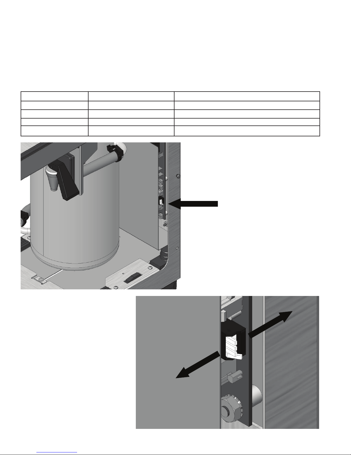
SWITCH SETTINGS
Program Switches:
1. Unplug the brewer and let it cool down before proceeding.
2. Remove the brew funnel.
3. Remove the front cover.
4. Flip the dip switches as needed (ON toward rear, OFF toward front)
NOTE: All switches are turned OFF from factory.
KEY # FUNCTION - OFF FUNCTION - ON
4. High altitude Set temp 200°F (93°C) Set temp 190°F (87.8°C)
3. Energy Save No energy save mode Drops to 140°F (60°C) @ 6 hours/OFF @ 26h
2. Brew lockout Brew @ any temp Only brews when it indicates ready
1. Program lockout Programming allowed All programming locked out
OFF
FIG 15
ON
1 2 3 4
FIG 16
Page 16
40410 092407
Page 17
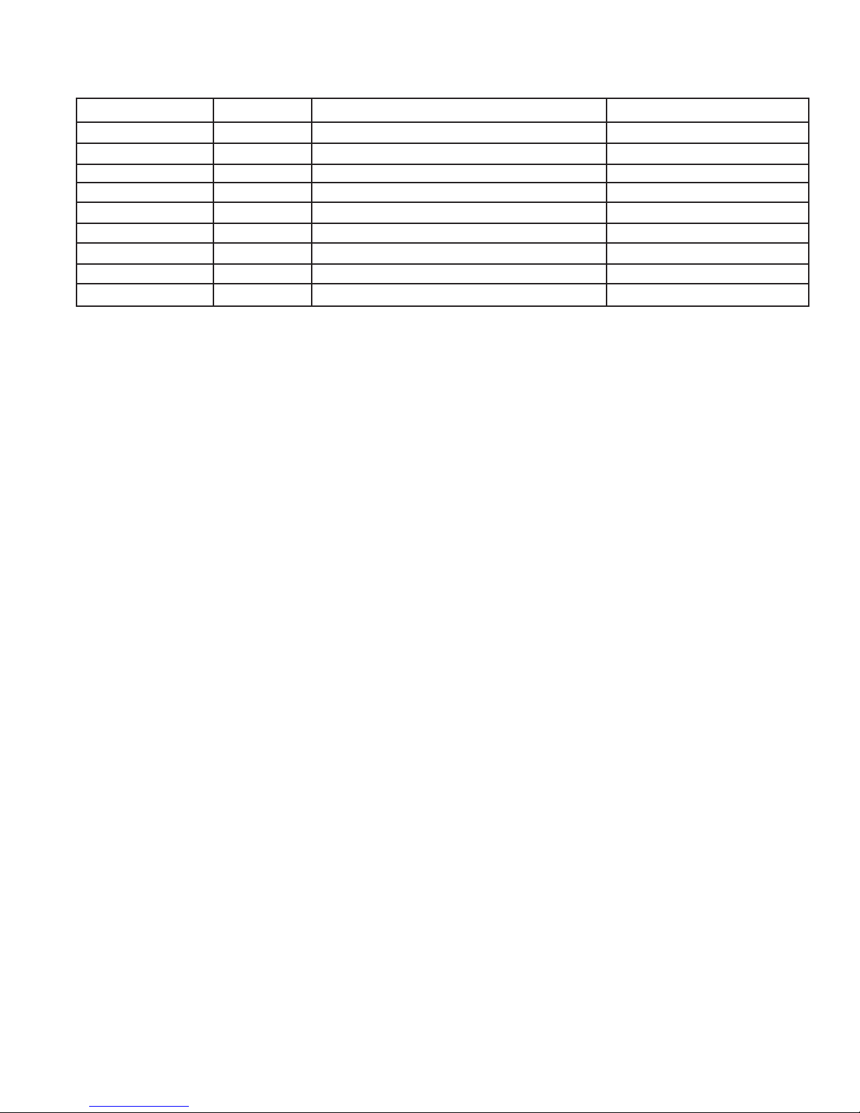
TROUBLESHOOTING
RED LED FLASHES DISPLAY DESCRIPTION ACTION
1. ER 1 TEMP SENSOR SHORTED CALL SERVICE
2. ER 2 TEMP SENSOR OPEN CALL SERVICE
3. ER 3 HEATING TOO LONG CALL SERVICE
4. ER 4 REFILL TOO LONG CHECK WATER SUPPLY
5. ER 5 HIGH TANK LEVEL-DURING BREW DELIME
6. ER 6 CHECK "ENABLE BREW ON/OFF" SWITCH CHECK SWITCH
7. ER 7 CHECK "BREW A"/"LARGE" SWITCH CHECK SWITCH
8. ER 8 CHECK "BREW B"/"LARGE" SWITCH CHECK SWITCH
Not Applicable ER 9 CHECK "HIDDEN" SWITCH CHECK SWITCH
Page 17
40410 092407
Page 18
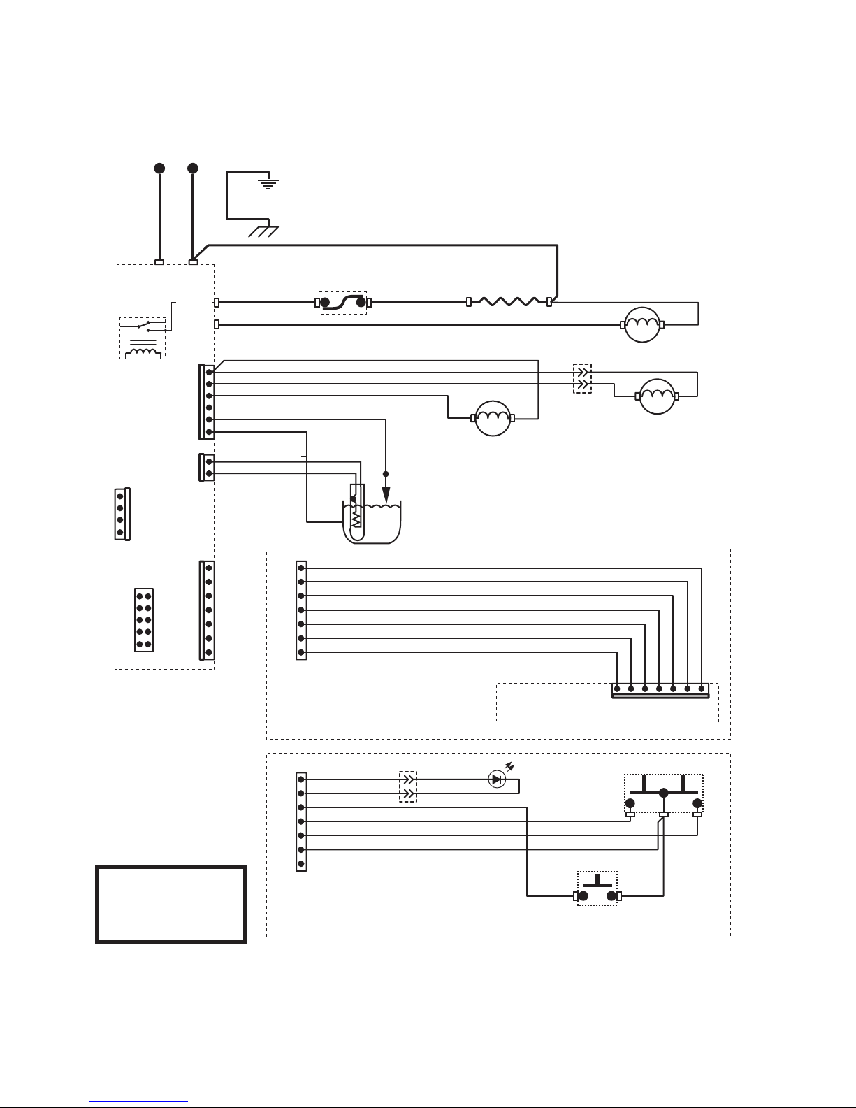
L1 N
BLK
WHI
SCHEMATIC WIRING DIAGRAM
WAVE 15 APS, 15 S APS
Earth Ground
GRN/YEL
WHI
Chassis Ground
RELAY
J5-1
10
6
L1 NT
J4
5
1
#
/
.
4
2
/
,
0
#
"
/
!
2
$
HEATER
WATER
J2-1
J3-1
J1-1
J1-5
LIMIT
J1-1
THERMOSTAT
GRN
RED
TAN
BLU
YEL
WHI/RED
ORN
BLK
RED/BLK
WHI/ORN +12
ORN +12
BRN - ON/0 OFF
RED/BLK - ON/0 OFF
PNK
GRN
BLK + .5V HOT 4.5V COLD
-
WHI
to
BLK-14
LEVEL PROBE
-12V
+12V
TANK HEATER
VENT VALVE SOLENOID
12VDC
WHI
WATER INLET SOLENOID
1
ORN
BRN
AIR PUMP MOTOR
12VDC
J1-1
120V AC
2 WIRE + GND
SINGLE PHASE
40405.0000B 09/07 ©2007 BUNN-O-MATIC CORPORATION
WAVE 15 APS
RED
BLK
WHI/BLK
BLU
YEL
ORN
WAVE 15 S APS
Page 18
DISPLAY BOARD
1
RED
BLK
ENABLE BREW
BREW START SWITCH
132
21
40410 092407
 Loading...