

Bunn Liquid Autofill Kits Installation Instructions Manual
ULTRA-1 & 2
INSTRUCTIONS FOR INSTALLING
LIQUID AUTOFILL KITS
INTRODUCTION
These instructions are for installing the Liquid Autofill Kits on Autofill ready ULTRA-1 and ULTRA-2 cold drink dispensers.
KIT CONTENTS ULT-2 ULT-1
A. 37567.0000 1* - Circuit Board, ULTRA 2 Auto-Fill
B. 37962.0001 1* - Wire Harness, AF Kit
C. 36329.0000 2 2 Tie, Cable-Nylon BLK 4.04"
D. 43120.xxxx 2 1 Cover Assy, Motor LAF-BLK
E. 38055.0003 2* 1 Probe Assy, LAF
F. 34362.0003 4* 2 Bushing .156" ID x .490" OD x .12" Flg
G. 00973.0000 4* 2 Nut, KEPS #6-32
H. 43131.0000 2 1 Bracket, Motor Cover Support
I. 43145.0000 2 1 Bracket, Motor Cover Mounting
J. 00970.0000 8 4 Nut, KEPS #8-32
K. 02308.0000 4 2 Screw, Pan Head, Slotted w/serr. #8-32 x .38"
L. 38129.0017 4 2 Hose, Braided .25 ID x 11.0" Lg
M. 21275.0006 8 4 Clamp .406/.504" Dia.
N. 01317.0000 4 2 Screw, Truss Head, Slotted #8-32 x .50"
O. 44194.0000 - 1 Wire Harness (Not Auto-fill Ready)
P. 44195.0000 - 1 Wire Harness (Auto-fill Ready)
* Not included in all kits.
INSTRUCTIONS
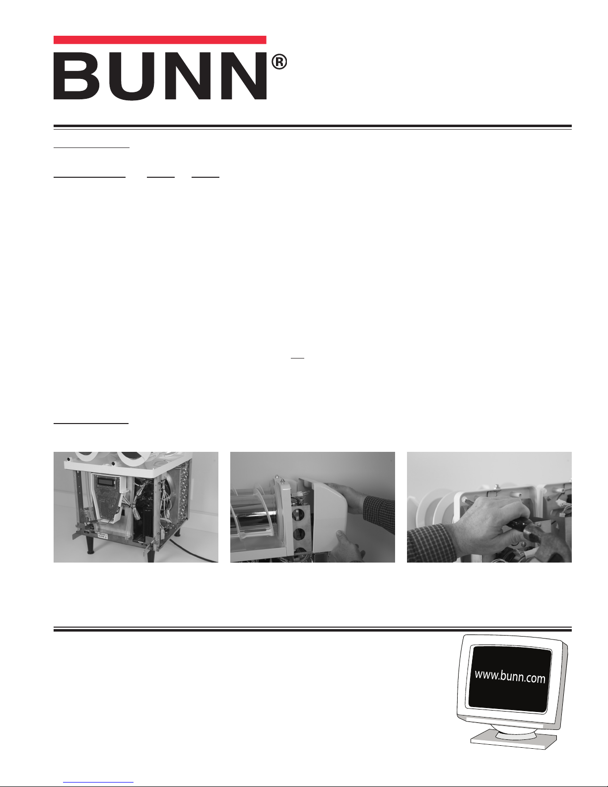
1. Unplug machine from power source before removing any panels.
2. Drain both hoppers and clean the machine if needed before proceeding.
3. Remove hoppers, drip tray, both side
panels and front panel.
4. Remove both motor covers and locate
.50" round knock out in top right area
of plastic drum mount. Discard screws.
(Continued)
BUNN-O-MATIC CORPORATION
POST OFFICE BOX 3227
SPRINGFIELD, ILLINOIS 62708-3227
PHONE: (217) 529-6601 FAX: (217) 529-6644
5. With a standard screwdriver and a
hammer, punch out the hole needed
for the level probe. Repeat this step
for all barrels.
37570.0002A 08/11 ©2011 Bunn-O-Matic Corporation
INSTRUCTIONS (Continued)
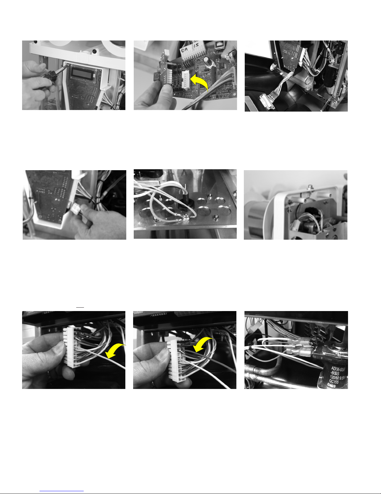
6. Remove 4 screws holding in the main
circuit board.
On ULTRA-1 Models, proceed to Step 12.
9. Plug wire harness (B) into Auto Fill
board connector and route wires in
front of drain tube and back into the
machine.
7. Connect Auto Fill board to J-12 on the
main board. Be sure to snap the plastic
stand off’s completely into the main
board.
10. Remove top nut off of grounding stud
in the base of the machine, add on the
green grounding wire from the new harness and reinstall the nut onto the stud.
Make sure that all the other grounding
wires remain on the ground stud.
8. Reinstall the main board into the
machine using the original mounting
screws.
11. Route Pink and Tan wires up to level
probes. To ease wire harness installation, remove both auger motors.
Note: valve connection wire colors –
right is red and white, left is blue and
white.
For ULTRA-1 Models not Auto-fill ready:
12. Disconnect main wiring harness from
circuit board. Insert pink wire from
Harness (Q) into terminal #6.
13. Insert red wire from Harness (Q) into
terminal #18.
NOTE: The pin terminal must be oriented
correctly to be inserted fully. After inserting
these connections, pull lightly on the wires
to insure they do not come out.
• Route new harness back into machine
along with the main harness.
(Continued)
2
14. Locate white wire on new harness with
piggy-back style spade connection.
Remove white wire from refrigerant
valve and connect piggy-back connector from new harness onto refrigerant
valve. Reconnect white wire from
main harness onto the new piggy-back
connector. Route remaining portion of
new harness toward the back of the
machine.
37570.2 081811
INSTRUCTIONS (Continued)
For ULTRA-1 Models that are Auto-fill ready:
15. Locate unused white and red auto-fill
valve wire connections tied in a bundle
on the main wiring harness. Carefully
cut wire tie to free the bundle.
16. Connect white and red wires from the
new harness (R) to white and red wires
repectively on the main harness. Route
the new harness toward the back of the
machine.
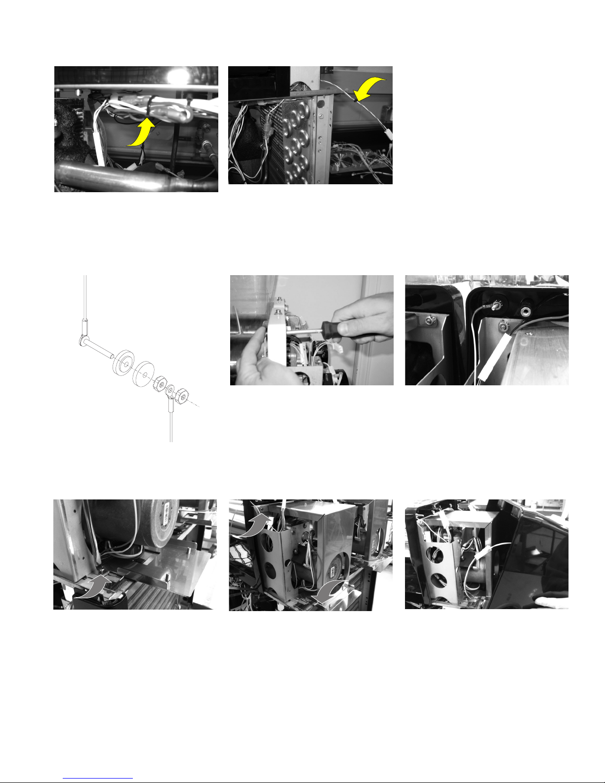
17. Install level probe assembly into hole
and secure with nuts provided (G).
18. Position wire and connector away from
metal bracket as shown. Attach using
nuts provided. Pink is the right probe
and Tan is the left probe. Reinstall motors using original screws.
19. Remove the two lower motor bracket
screws and align new bracket in place.
Attach with new screws (K ) provided.
20. Install larger metal bracket as shown.
Route light connection wires above
plastic boss to keep from being pinched
under the new mounting bracket. Route
torque sensor wires away to keep from
being pinched under metal mounting
bracket Secure with 4 nuts (J ) provided.
(Continued)
3
21. Connect harness to each new motor
cover assembly with Auto Fill, then
mount motor cover to machine with
new screws (N ) provided.
Hint: Align the motor cover in at the
top, then snap the bottom in place.
37570.2 081811
 Loading...