

Page 1
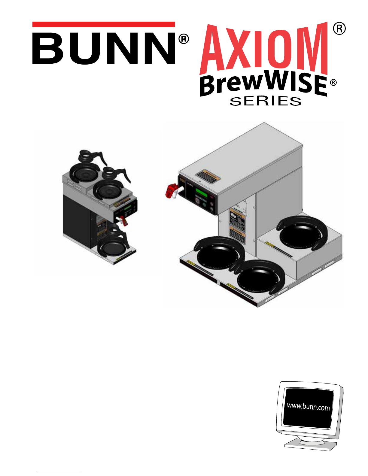
INSTALLATION & OPERATING GUIDE
BUNN-O-MATIC CORPORATION
PHONE: (217) 529-6601 FAX: (217) 529-6644
To ensure you have the latest revision of the Operating Manual, or to view the Illustrated Parts
Catalog, Programming Manual, or Service Manual, please visit the Bunn-O-Matic website, at
www.bunn.com. This is absolutely FREE, and the quickest way to obtain the latest catalog and
manual updates. For Technical Service, contact Bunn-O-Matic Corporation at 1-800-286-6070.
39130.0004B 03/13 ©2012 Bunn-O-Matic Corporation
POST OFFICE BOX 3227
SPRINGFIELD, ILLINOIS 62708-3227
Page 2

BUNN-O-MATIC COMMERCIAL PRODUCT WARRANTY
Bunn-O-Matic Corp. (“BUNN”) warrants equipment manufactured by it as follows:
1) Airpots, thermal carafes, decanters, GPR servers, iced tea/coffee dispensers, MCP/MCA pod brewers thermal servers
and Thermofresh servers (mechanical and digital)- 1 year parts and 1 year labor.
2) All other equipment - 2 years parts and 1 year labor plus added warranties as specified below:
a) Electronic circuit and/or control boards - parts and labor for 3 years.
b) Compressors on refrigeration equipment - 5 years parts and 1 year labor.
c) Grinding burrs on coffee grinding equipment to grind coffee to meet original factory screen sieve analysis - parts
and labor for 4 years or 40,000 pounds of coffee, whichever comes first.
These warranty periods run from the date of installation BUNN warrants that the equipment manufactured by it will be
commercially free of defects in material and workmanship existing at the time of manufacture and appearing within the
applicable warranty period. This warranty does not apply to any equipment, component or part that was not manufactured
by BUNN or that, in BUNN’s judgment, has been affected by misuse, neglect, alteration, improper installation or operation,
improper maintenance or repair, non periodic cleaning and descaling, equipment failures related to poor water quality,
damage or casualty. In addition, the warranty does not apply to replacement of items subject to normal use including but
not limited to user replaceable parts such as seals and gaskets. This warranty is conditioned on the Buyer 1) giving BUNN
prompt notice of any claim to be made under this warranty by telephone at (217) 529-6601 or by writing to Post Office
Box 3227, Springfield, Illinois 62708-3227; 2) if requested by BUNN, shipping the defective equipment prepaid to an
authorized BUNN service location; and 3) receiving prior authorization from BUNN that the defective equipment is under
warranty.
THE FOREGOING WARRANTY IS EXCLUSIVE AND IS IN LIEU OF ANY OTHER WARRANTY, WRITTEN OR ORAL, EXPRESS OR IMPLIED, INCLUDING, BUT NOT LIMITED TO, ANY IMPLIED WARRANTY OF EITHER MERCHANTABILITY
OR FITNESS FOR A PARTICULAR PURPOSE. The agents, dealers or employees of BUNN are not authorized to make
modifications to this warranty or to make additional warranties that are binding on BUNN. Accordingly, statements by such
individuals, whether oral or written, do not constitute warranties and should not be relied upon.
If BUNN determines in its sole discretion that the equipment does not conform to the warranty, BUNN, at its exclusive option while the equipment is under warranty, shall either 1) provide at no charge replacement parts and/or labor (during the
applicable parts and labor warranty periods specified above) to repair the defective components, provided that this repair
is done by a BUNN Authorized Service Representative; or 2) shall replace the equipment or refund the purchase price for
the equipment.
THE BUYER’S REMEDY AGAINST BUNN FOR THE BREACH OF ANY OBLIGATION ARISING OUT OF THE SALE OF THIS
EQUIPMENT, WHETHER DERIVED FROM WARRANTY OR OTHERWISE, SHALL BE LIMITED, AT BUNN’S SOLE OPTION
AS SPECIFIED HEREIN, TO REPAIR, REPLACEMENT OR REFUND.
In no event shall BUNN be liable for any other damage or loss, including, but not limited to, lost profits, lost sales, loss of
use of equipment, claims of Buyer’s customers, cost of capital, cost of down time, cost of substitute equipment, facilities
or services, or any other special, incidental or consequential damages.
392, A Partner You Can Count On, Air Infusion, AutoPOD, AXIOM, BrewLOGIC, BrewMETER, Brew Better Not Bitter, BrewWISE, BrewWIZARD, BUNN Espress, BUNN Family Gourmet, BUNN Gourmet, BUNN Pour-O-Matic, BUNN, BUNN with
the stylized red line, BUNNlink, Bunn-OMatic, Bunn-O-Matic, BUNNserve, BUNNSERVE with the stylized wrench design,
Cool Froth, DBC, Dr. Brew stylized Dr. design, Dual, Easy Pour, EasyClear, EasyGard, FlavorGard, Gourmet Ice, Gourmet
Juice, High Intensity, iMIX, Infusion Series, Intellisteam, My Café, Phase Brew, PowerLogic, Quality Beverage Equipment
Worldwide, Respect Earth, Respect Earth with the stylized leaf and coffee cherry design, Safety-Fresh, savemycoffee.com,
Scale-Pro, Silver Series, Single, Smart Funnel, Smart Hopper, SmartWAVE, Soft Heat, SplashGard, The Mark of Quality
in Beverage Equipment Worldwide, ThermoFresh, Titan, trifecta, Velocity Brew, Air Brew, Beverage Bar Creator, Beverage Profit Calculator, Brew better, not bitter., BUNNSource, Coffee At Its Best, Cyclonic Heating System, Daypart, Digital
Brewer Control, Element, Nothing Brews Like a BUNN, Pouring Profits, Signature Series, Tea At Its Best, The Horizontal
Red Line, Ultra are either trademarks or registered trademarks of Bunn-O-Matic Corporation. The commercial trifecta®
brewer housing configuration is a trademark of Bunn-O-Matic Corporation.
Page 2
39130.4 021513
Page 3
PN: 00658.0000G 02/08 © 1985 BUNN-O-MATIC CORPORATION
WARMERS AND SURFACES ARE HOT
CAUTION
INTRODUCTION
This equipment will brew a 1⁄2 gallon batch of coffee into an awaiting server. The brewer may have
a hot water faucet for allied beverage use. It is only for indoor use on a sturdy counter or shelf.
CONTENTS
Warranty ................................................................................................ 2
User Notices ......................................................................................... 3
Electrical Requirements ........................................................................ 4
Plumbing Requirements & Initial Set-Up ............................................... 6
Operating Controls & Coffee Brewing ................................................... 7
Cleaning & Tank Drain .......................................................................... 8
Adjustments & Optional Settings .......................................................... 9
USER NOTICES
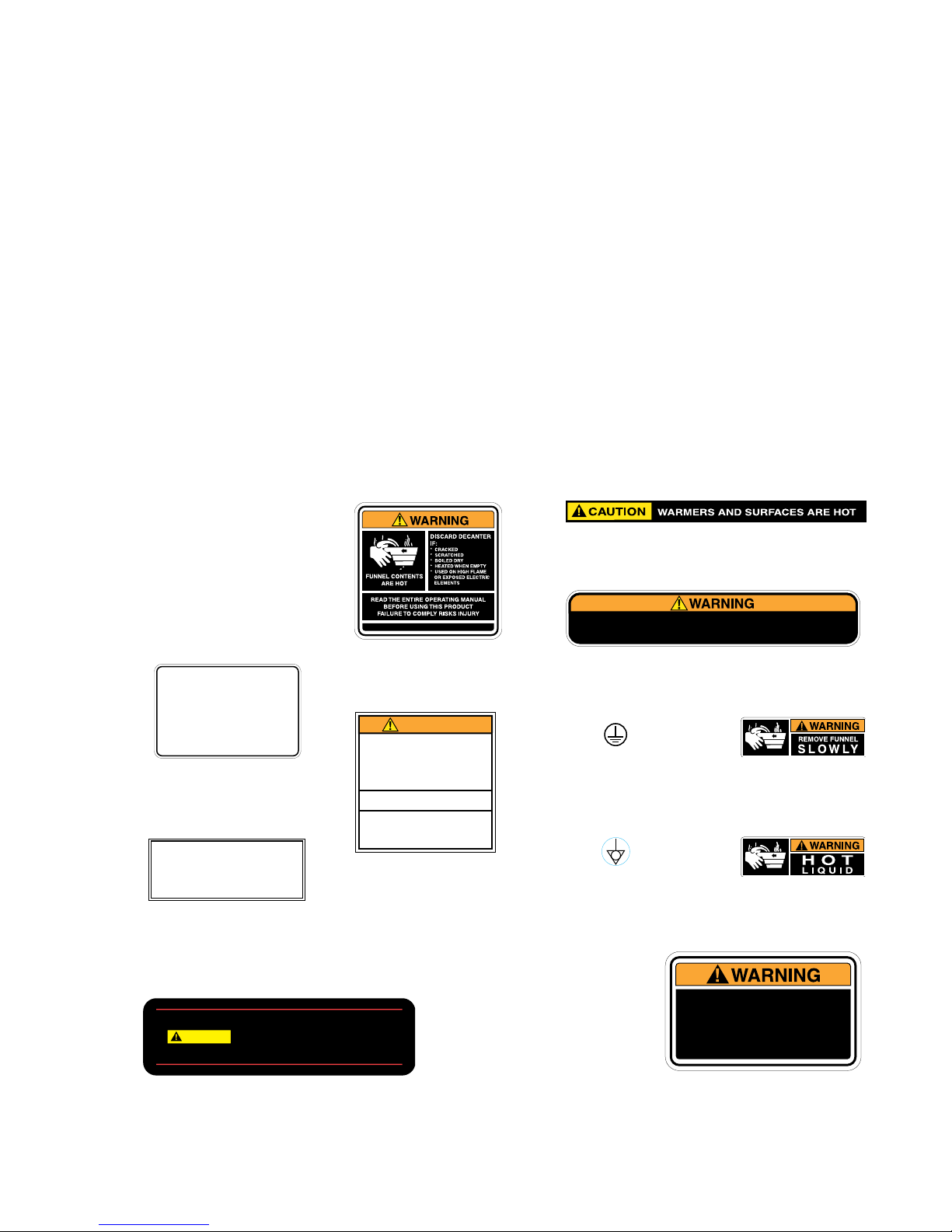
Carefully read and follow all notices in this manual and on the equipment. All labels on the equipment should
be kept in good condition. Replace any unreadable or damaged labels.
Optional Field Wiring
120/208-240 V, 15.6-17.5 A, 2980-3850 W
1PH, 3-Wire + GND, 60HZ
#29710.0007
As directed in the International Plumbing Code of the
International Code Council and the Food Code
Manual of the Food and Drug Administration (FDA),
this equipment must be installed with adequate
backflow prevention to comply with federal, state
and local codes. For models installed outside the
U.S.A., you must comply with the applicable Plumbing /Sanitation Code for your area.
#00656.0001
#00658.0000
WARNING
• DO NOT OVERLOAD CIRCUIT.
• ALWAYS ELECTRICALLY GROUND
THE CHASSIS.
• DO NOT DEFORM PLUG OR CORD.
• FOLLOW NATIONAL AND LOCAL
ELECTRICAL CODES.
• KEEP COMBUSTIBLES AWAY.
FAILURE TO COMPLY RISKS EQUIPMENT
DAMAGE, FIRE OR SHOCK HAZARD.
READ THE ENTIRE
OPERATING MANUAL BEFORE
USING THIS PRODUCT
00986.0000F 10/07 ©1994 Bunn-O-Matic Corporation
#00986.0000
#12364.0000
To reduce the risk of electric shock,
do not remove or open cover.
No user-serviceable parts inside.
#37881.0002
#00824.0002
#00824.0001
Authorized service personnel only.
Disconnect power before servicing.
#03408.0002
#03409.0002
#02765.0000
Page 3
To reduce the risk of electric shock,
do not remove or open cover.
No user-serviceable parts inside.
Authorized service personnel only.
Disconnect power before servicing.
#37881.0000
39130.4 040212
Page 4

ELECTRICAL REQUIREMENTS
WARNING -
The brewer must be disconnected from the power source until specified in Initial Set-Up.
Refer to Data Plate on the Brewer, and local/national electrical codes to determine circuit requirements.
ELECTRICAL HOOK-UP (All Models)
CAUTION – Improper electrical installation will damage electronic components.
1. An electrician must provide electrical service.
2. Determine the available on-site electrical service.
3. Select the desired unit voltage based on the available on-site electrical service.
4. Using a voltmeter, check the voltage and color coding of each conductor at the electrical source.
5. Remove the front access panel beneath the sprayhead to gain access to the terminal block.
6. Feed the supply leads through the rear of the brewer.
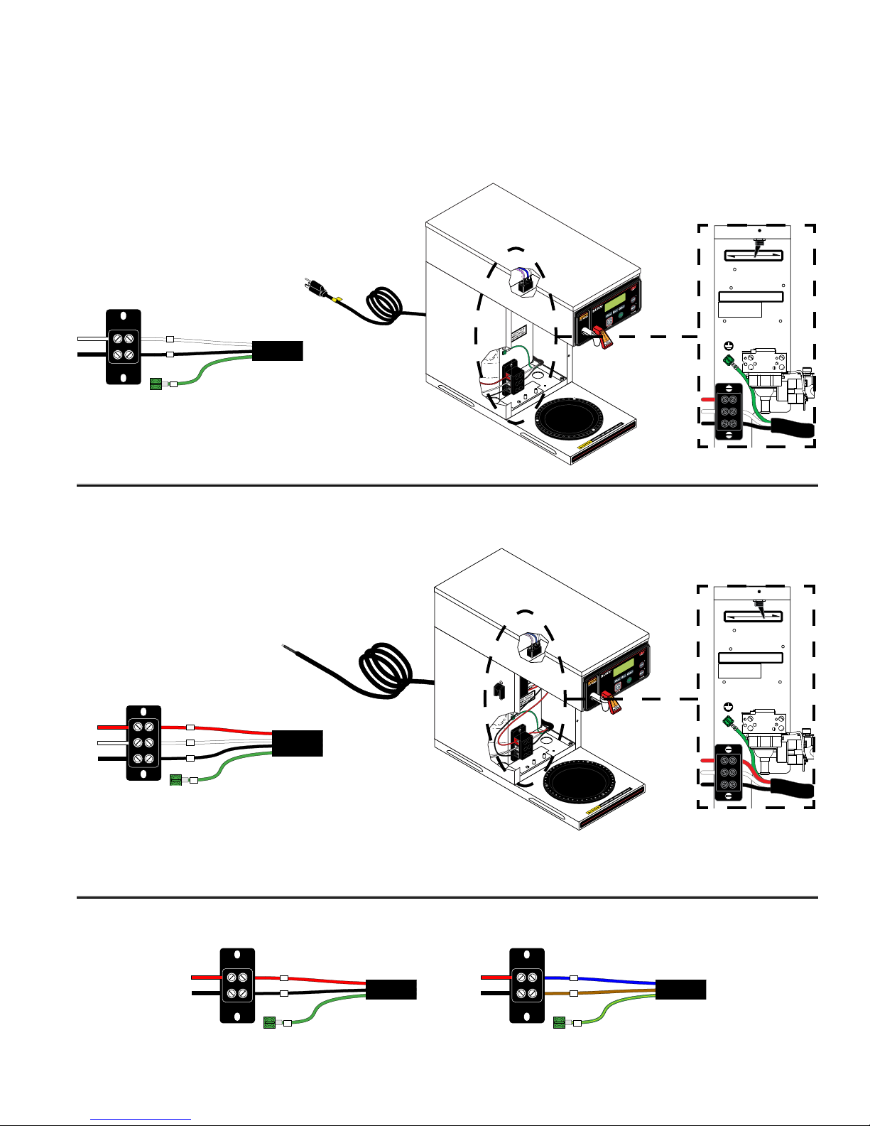
7. Using the above diagrams, connect the desired electrical service to the field wiring terminal block.
8. If wiring the machine for operation on 120/208 or 120/240 volts with a Power Supply Cord, the Power
Supply Cord must be UL Listed Flexible Cord Type SO, SJO, SJTO, HSJO or SJOW, No. 12 AWG, 4 Conductor, Rated 90° C. Attachment Plug Cap must be UL Listed, NEMA 14-20P or L14-20P Configuration,
Rated 125/250V, 20 AMPS. The Power Supply Cord must be at least 3 feet long and maximum 6 feet long
(measured from Strain Relief to end of the Attachment Plug Cap).
9. Before proceeding, verify the voltage at the field wiring terminal block.
10. Set voltage switch to the appropriate position and replace the access panel. (DV Models Only)
11. If plumbing is to be hooked up later be sure the brewer is disconnected from the power source. If
plumbing has been hooked up, the brewer is ready for Initial Set-Up.
CE REQUIREMENTS
• This appliance must be installed in locations where it can be overseen by trained personnel.
• For proper operation, this appliance must be installed where the temperature is between 5°C to 35°C.
• Appliance shall not be tilted more than 10° for safe operation.
• An electrician must provide electrical service as specied in conformance with all local and national codes.
• This appliance must not be cleaned by water jet.
• This appliance is not intended for use by persons (including children) with reduced physical, sensory or mental
capabilities, or lack of experience and knowledge, unless they have been given instructions concerning use of
this appliance by a person responsible for its safety.
• Children should be supervised to ensure they do not play with the appliance.
• If the power cord is ever damaged, it must be replaced by the manufacturer or authorized service personnel with
a special cord available from the manufacturer or its authorized service personnel in order to avoid a hazard.
• Machine must not be immersed for cleaning.
Note: This electrical service requires
3 current carrying conductors (Neutral,
L1 and L2) and a separate conductor for
earth ground.
Twins
Page 4
All Twins are 120/208 & 120/240V AC
Single phase unless otherwise noted.
Note: Power cord must be
connected to center terminal
block on all Twins unless
otherwise noted.
39130.4 040212
Page 5
ELECTRICAL REQUIREMENTS
120V
120/208-240V
For Supply Connections, Use No. 12 AWG
Wires Suitable For At Least 90°C (194°F)
FOR USE ONLY ON AN
INDIVIDUAL BRANCH
CIRCUIT RATED 20 AMPS
120V
120/208-240V
For Supply Connections, Use No. 12 AWG
Wires Suitable For At Least 90°C (194°F)
FOR USE ONLY ON AN
INDIVIDUAL BRANCH
CIRCUIT RATED 20 AMPS
Single & Dual Volt Models
Requirements for brewers with an attached cord set are as follows:
Note: This electrical service re-
quires 2 current carrying conductors (Neutral, and L1) and a separate
conductor for earth ground.
Dual Voltage Switch
in 120V position
L1 BLACK
WHITENEUTRAL
N
L1
GREEN
G
POWER CORD
WHITE
NEUTRAL
L1 BLACK
120V 2 WIRE + GROUND
120V AC
Single phase models
Requirements for brewers without an attached cord set are as follows:
Dual Voltage Switch in
Note: This electrical service
120/208-240V position
require 3 current carrying
conductors (Neutral, L1 and
L2) and a separate conductor
for earth ground
L2 RED L2 RED
WHITE
NEUTRAL
L1 BLACK
L1 BLACK
L2
WHITENEUTRAL
N
L1
GREEN
G
POWER CORD
120/208-240V 3 WIRE + GROUND
L2 RED L2 RED
L1 BLACK
L1 BLACK
L2
L1
GREEN
G
208-240V 2 WIRE + GROUND
120/208 & 120/240V AC
Single phase models
POWER CORD
L2 RED NEUTRAL BLUE
L1 BLACK
220-240V 2 WIRE + GROUND
Page 5
L1 BROWN
N
L1
GREEN/YELLOW
G
POWER CORD
39130.4 030613
Page 6
-1000 213.8 101.0 200 93.3
-500 212.9 100.5 200 93.3
0 212.0 100.0 200 93.3
500 211.1 99.5 200 93.3
1000 210.2 99.0 200 93.3
1500 209.3 98.5 200 93.3
2000 208.4 98.0 200 93.3
2500 207.4 97.4 200 93.3
3000 206.5 96.9 199 92.8
3500 205.6 96.4 198 92.2
4000 204.7 95.9 197 91.7
4500 203.8 95.4 196 91.1
5000 202.9 94.9 195 90.6
5500 201.9 94.4 195 90.6
6000 201.0 93.9 194 90.0
6500 200.1 93.4 193 89.4
7000 199.2 92.9 192 88.9
7500 198.3 92.4 191 88.3
8000 197.4 91.9 190 87.8
8500 196.5 91.4 189 87.2
9000 195.5 90.8 188 86.7
9500 194.6 90.3 187 86.1
10000 193.7 89.8 186 85.6
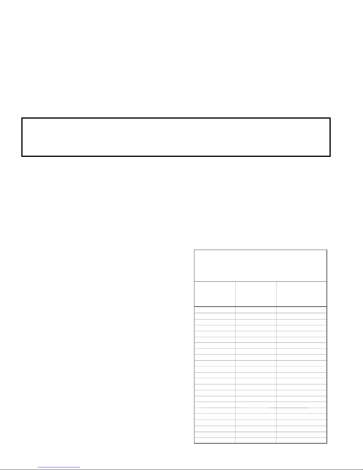
Brew water temperature is factory set at 200° F (93.3° C)
Areas of high altitude will require lowering this temperature to prevent boiling. This chart should be used as a
guide when readjusting the brew water temperature.
Altitude
(Feet)
Boiling point
of water
° F ° C
Recommended
water temperature
° F ° C
PLUMBING REQUIREMENTS
These brewers must be connected to a cold water system with operating pressure between 20
and 90 psi (138 and 620 kPa) from a 1⁄2" or larger supply line. A shut-off valve should be installed in
the line before the brewer. Install a regulator in the line when pressure is greater than 90 psi (620
kPa) to reduce it to 50 psi (345 kPa). The water inlet fitting is
1
⁄4" flare.
NOTE - Bunn-O-Matic recommends 1⁄4" copper tubing for installations of less than 25 feet and 3⁄8"
for more than 25 feet from the
1
⁄2" water supply line. A tight coil of copper tubing in the water line will
facilitate moving the brewer to clean the counter top. Bunn-O-Matic does not recommend the use of
a saddle valve to install the brewer. The size and shape of the hole made in the supply line by this
type of device may restrict water flow.
As directed in the International Plumbing Code of the International Code Council and the Food Code
Manual of the Food and Drug Administration (FDA), this equipment must be installed with adequate
backflow prevention to comply with federal, state and local codes. For models installed outside the
U.S.A., you must comply with the applicable Plumbing /Sanitation Code for your area.
1. Flush the water line and securely attach it to the inlet fitting at the rear of the brewer.
2. Turn on the water supply.
INITIAL SET-UP
1. Insert an empty funnel into the funnel rails.
2. Place an empty server under the funnel.
3. Connect the brewer to the power source.
4. Turn on the main ON/OFF switch located on the
left side or back of brewer (If equipped).
5. Water will flow into the tank and stop when the tank
is filled to its capacity. Display will show "PLEASE
WAIT...TANK FILLING" until tank is filled with
water.
6. Wait approximately twenty minutes for the water
in the tank to heat to the proper temperature.
Display will show "READY TO BREW...WATER
TEMP: 200°" when tank is at operating temperature. Some water will drip from the funnel during
this time; this is due to expansion and should not
occur thereafter.
7. Place a small container beneath the faucet and
open the faucet handle. Release it when you hear
the tank refilling.
8. Water volumes and flow settings have been preset
at the factory. Refer to adjustments for the Set
Brew Volumes section of this manual should the
volume need to be increased or decreased.
9. The brewer is now ready for use in accordance
with the instructions for Coffee Brewing.
10. Repeat steps 5-9 for remaining side on Twins.
Page 6
If setting up new brewer in high mineral
locations, refer to programming (Enable
Brew Logic). Pertains to units with
software version 1.06 & up.
39130.4 040212
Page 7
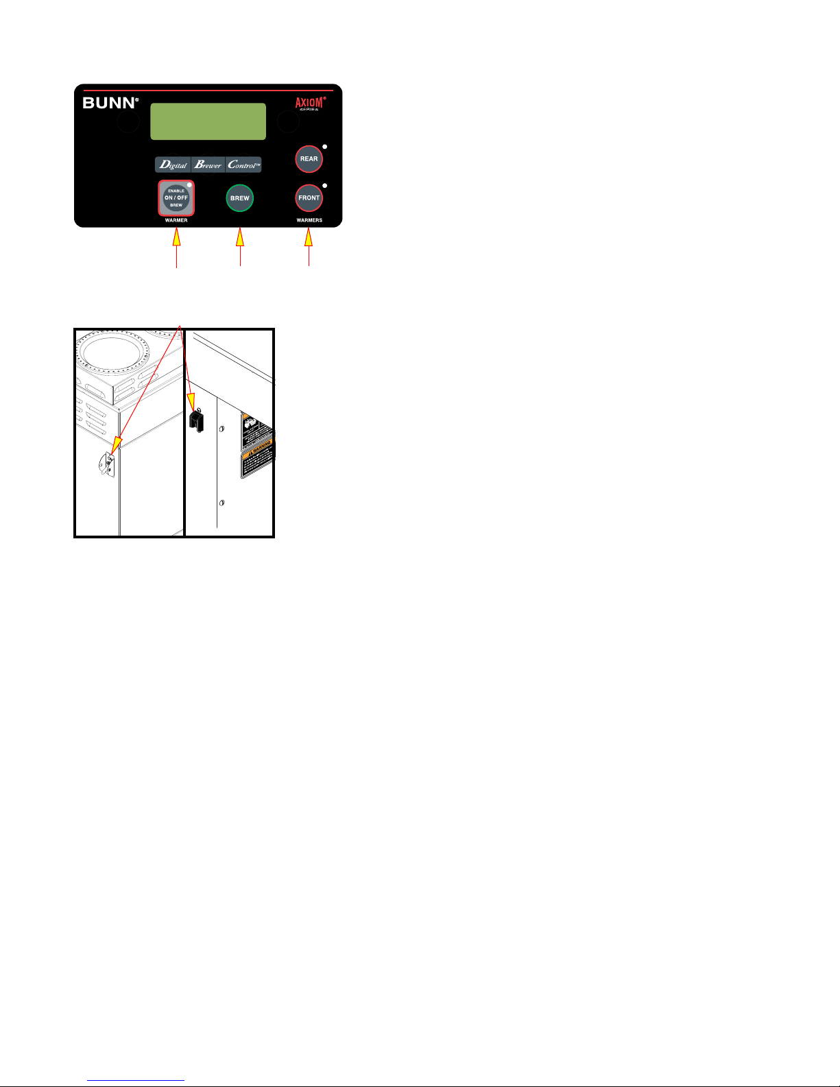
OPERATING CONTROLS
(A) ENABLE BREW ON/OFF SWITCH
Pressing the "ENABLE BREW ON/OFF" switch (indicator on)
supplies power to the brew station warmer and enables the
brew circuit. Pressing the switch again (indicator off) stops
brewing and de-energizes the brew station warmer. Stopping
a brew cycle after it has been started will not stop the flow
of water into the server until the funnel is empty.
P3633
A
B
C
(B) BREW SWITCH
Momentarily pressing and releasing the switch starts a
brew cycle when the "ENABLE BREW ON/OFF" indicator
D
is on.
(C) ADDITIONAL WARMER SWITCHES
Pressing any additional warmer switch so that the indicator is on,
supplies power to the associated warmer. NOTE: APS & TC models
have no warmers.
(D) MAIN ON/OFF SWITCH
This switch, located on the left side of the brewer, turns power on and off
to all components in the brewer.
P3969.50
COFFEE BREWING
1. Begin each brew cycle with a clean empty brew funnel.
2. Insert a BUNN filter into the funnel.
3. Pour (or grind) fresh coffee into the filter and level the bed of grounds by gently shaking.
4. Slide the funnel into the funnel rails until it stops.
5. Place an empty server under the funnel.
6. Verify that the "ENABLE BREW ON/OFF" indicator is on.
7. Momentarily press and release the "BREW" switch. The display will read "NOW BREWING", and
show the time remaining in the brew cycle.
8. Following the brew, the display reads "DRIPPING" which shows the time remaining until the coffee no longer drips from the funnel tip.
9. After the coffee finishes dripping from the funnel tip, carefully remove the brew funnel and discard
the grounds and filter.
Page 7
39130.4 040212
Page 8
CLEANING
1. The use of a damp cloth rinsed in any mild, nonabrasive, liquid detergent is recommended for
cleaning all surfaces on Bunn-O-Matic equipment.
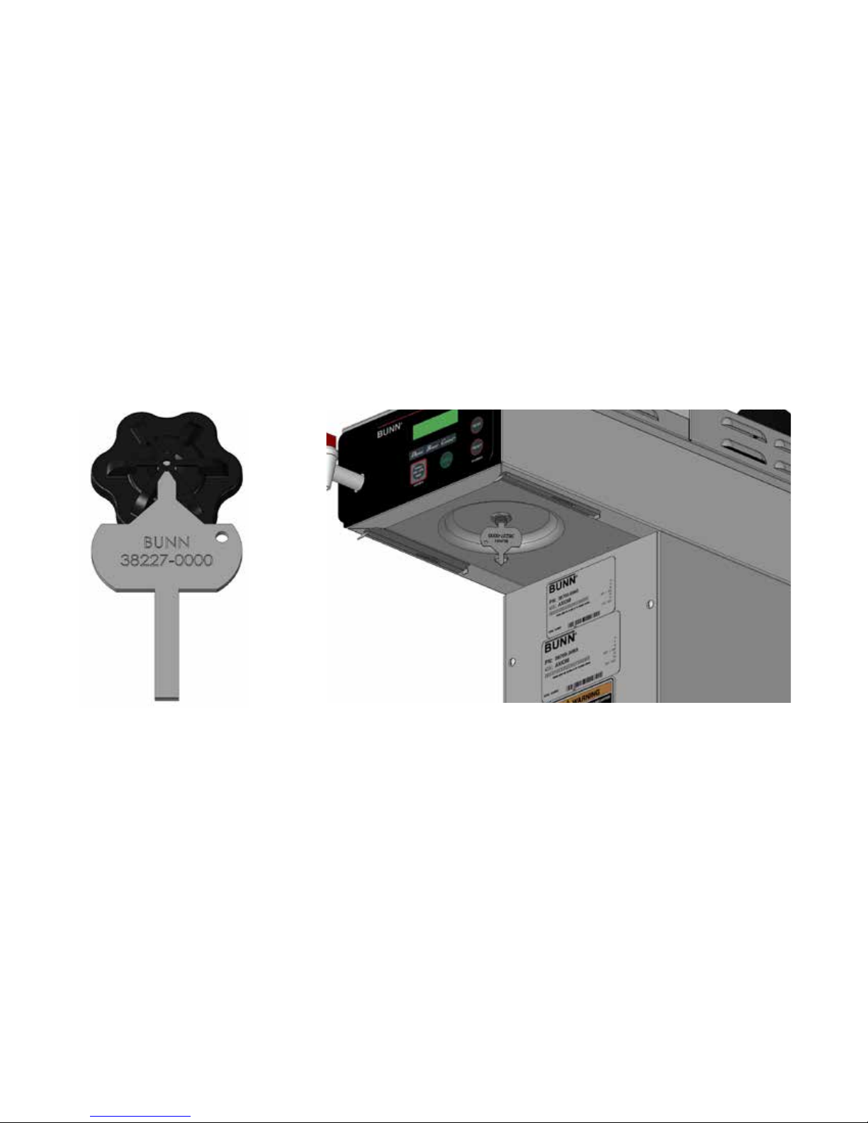
2. Check and clean the sprayhead. The sprayhead holes must always remain open. Insert the short
end of the sprayhead cleaning tool into each of the five water outlets of the plastic sprayhead to
remove any mineral deposits (Refer to Fig 1)
3. Insert the long end of sprayhead cleaning tool into the sprayhead fitting, and rotate several times
to remove any mineral deposits from the fitting (Refer to Fig 2).
NOTE: In hard water areas, this may need to be done daily. It will help prevent liming problems in
the brewer and takes less than a minute.
NOTE: In the event that the "Brew Logic" circuit activates (compensating for high lime build up), it
will temporarily disable the "Recovery Booster" and "Pulse Brewing" systems until the unit has been
de-limed. Refer to the Troubleshooting section for more details.
FIGURE 1 FIGURE 2
1. Loosen screws that secure the front access panel. Remove the panel.
2. Unfasten the hose clamp at the end of the drain hose. Remove the plug.
3. Place the end of the drain hose in a container that has a minimum capacity of 200 oz (5.9 L).
4. Release the white clamp to drain water from the tank.
5. When tank is empty, close the white clamp, replace the plug, and tighten the clamp at the end
of the drain hose. (Repeat steps 2-5 for remaining side on Twins)
6. Replace the front panel and tighten screws.
TANK DRAIN
Page 8
39130.4 040212
Page 9
ADJUSTMENTS & OPTIONAL SETTINGS
BUNN
3
®
1
2
READY TO BREW
WATER TEMP: 200°
REAR
5
FRONT
WARMER
5
4
WARMERS
P3633
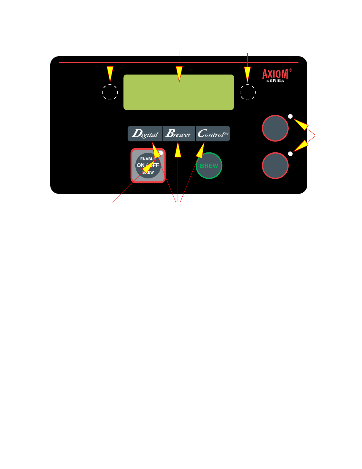
Using the menu-driven display on the front of the brewer, the operator has the ability to alter or
modify various brewing parameters such as brew lockout, brew volume, brew strength, etc. This
allows for the precise brewing of various flavors of coffee.
Programming of the brewer is achieved by entering a certain function. Then, by the use of hidden
programming switches, the operator can customize the brewing process to their specifications.
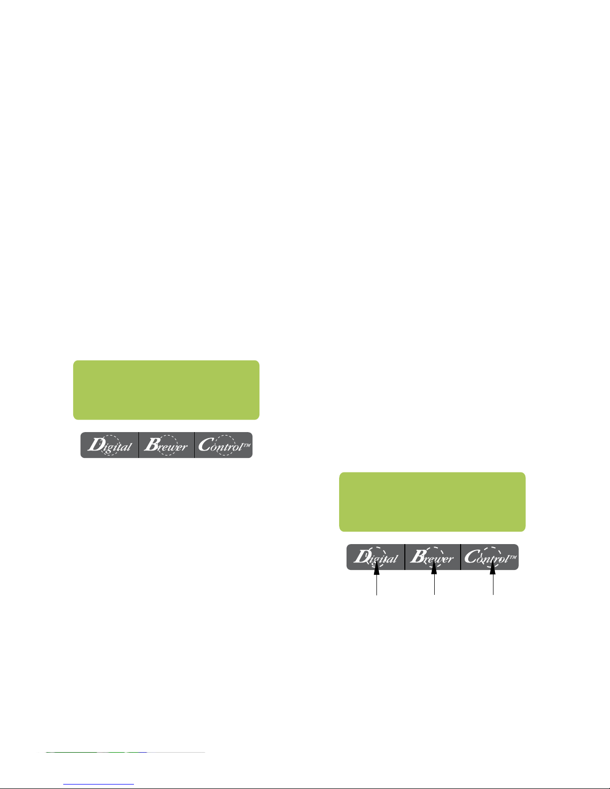
PROGRAMMING SWITCHES
1. FUNCTION SCREEN
This is the display which shows the various functions.
2. (Right of the display)
This is used to access the program mode and is also used to step forward through the menu.
3. (Left of the display)
This is used to step backwards through the function list.
4. "Digital" (lower left under the display)
This is used to select options that appear on the display during programming (NO/-)
"Brewer" (center under the display)
This is used to select options that appear on the display during programming (DONE)
"Control" (lower right under the display)
This is used to select options that appear on the display during programming (YES/+)
5. FUNCTION SCREEN
This is the display
Page 9
39130.4 040212
Page 10
ADJUSTMENTS & OPTIONAL SETTINGS (CONT.)
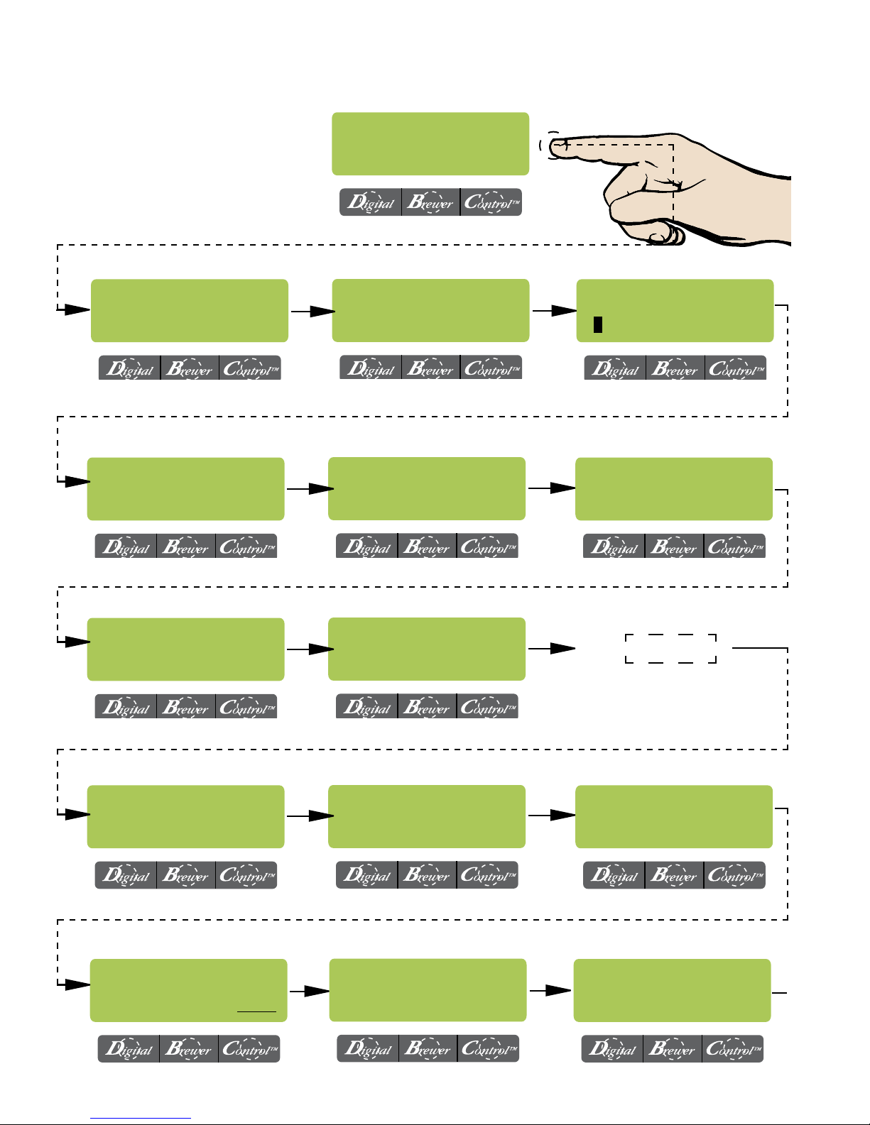
PROGRAMMING FUNCTIONS
OVERVIEW
BrewWIZARD
BREW LOCKOUT ?
NO DONE YES
SPRAY OZ/M: 25.0
(-) DONE (+)
ENTER SERVICE #?
NO YES
BREW OZ: 60.0
(-) DONE (+)
CALIBRATE FLOW ?
NO YES
EXITING
BrewWIZARD
BREW METER 1
- +
ENABLE ADS ?
NO DONE YES
LEVEL 2
ENTER PASSWORD
0 0 0
UNITS
METRIC DONE ENG
SET PASSWORD
0 0 0
SET TEMP: 200°
(-) DONE (+)
Page 10
SET LANGUAGE ?
NO YES
SET READY: 195°
(-) DONE (+)
39130 020608
39130.4 040212
Page 11
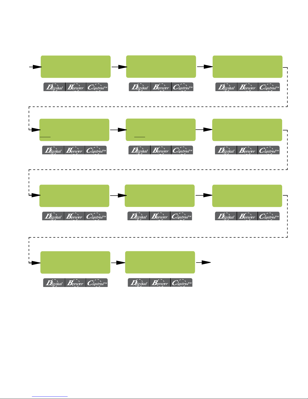
LEVEL 2 (CONT.)
ADJUSTMENTS & OPTIONAL SETTINGS (CONT.)
ENTER ASSET # ?
NO YES
ENABLE CLEAN
NO DONE YES
ENABLE BrewLOGIC
NO DONE YES
SET PULSE BREW ?
NO YES
Enabl EnergySavr
NO DONE YES
BREW COUNTERS ?
NO YES
DRIP TIME 1:00
(-) DONE (+)
0 REFILL 155
(-) DONE (+)
SERVICE TOOLS ?
NO YES
FACTORY DEFAULTS
NO YES
AXIOM
VERSION xx.xx
Page 11
Return To Main Screen
39130.4 040212
Page 12
ADJUSTMENTS & OPTIONAL SETTINGS
PROGRAMMING THE BREWER
The programming of the brewer is divided into two levels. Brewing adjustments are in "BrewWizard". Service functions are accessed in Level 2.
The following function screens are in order of appearance. Each screen will have instructions on
how to access, and the procedures to program the various functions of the brewer.
IMPORTANT PROGRAMMING NOTES
- READ CAREFULLY -
To exit the programming mode at any time, press and release "ENABLE BREW ON/OFF" switch
located on the front switch panel. The display will return to the MAIN SCREEN.
If none of the five programming switches are pressed within one minute during the setup of the
brewer, the programming of the function screen that is being set will be exited and the display will
return to the MAIN SCREEN.
Always remember to place an empty server and funnel under the sprayhead when operating the
brewer during the set-up of PULSE BREW, CALIBRATE FLOW and testing the brew valve in SERVICE TOOLS/TEST OUTPUTS.
PROGRAM FUNCTIONS - BREW WIZARD
MAIN SCREEN
READY TO BREW
WATER TEMP: 200°
PROGRAMMING LOCKOUT SWITCH
The main screen will alternate between "READY
This switch can be set to prevent access to the
TO BREW"/"WATER TEMP" and TIME/DATE/
programming settings of the brewer. Once all the
YEAR. Will also indicate if the glass or thermal
correct brew settings are programmed, the operator
carafes are ready to brew into (green lights) or
can set the switch to the "LOCK" position to prohibit
almost expired (yellow lights) or expired (red
anyone from changing the settings. With the switch
lights)
(Mounted on main control board)
in the "LOCK" position, the programming menus
can still be accessed to view the current settings.
However, no changes will be saved.
MAIN SCREEN
BREW LOCKOUT
This function allows the operator to prevent
or allow brewing if the water temperature is less
than the set READY temperature.
To access this function screen press and hold
the right hidden switch. Release when the display
reads: "BREW WIZARD" it will then read:
BREW LOCKOUT?
NO DONE YES
Press here
for NO
Press here
for DONE
Press here
for YES
LOCK
SET
Disconnect brewer from
power source before
removing any panel!
Page 12
The YES or NO should be flashing. Select YES
to prevent brewing if the water temperature is
below the set READY temperature. Select NO
to permit brewing at any water temperature.
When finished, press and release DONE. This
will step to the next function screen. To return
to the MAIN SCREEN at any time, press and
release "ENABLE BREW ON/OFF".
39130.4 040212
Page 13
ADJUSTMENTS & OPTIONAL SETTINGS (CONT.)
PROGRAMMING FUNCTIONS - BrewWIZARD (cont.)
The functions in the "BrewWIZARD" allow the operator to adjust brew settings and other features.
BREW OZ:
This function allows the operator to adjust the brew volume.
Procedure:
1. Press and hold the right hidden switch until the display reads "BrewWIZARD" and release.
2. The display will then read: "BREW OZ: xx.x"
3. Press (-) "Digital" to decrease the amount, or (+) "Control" to increase.
Range: (10 to 192 oz., in .5 oz. increments) or (.30 to 6.60 Liters, in .01 increments)
4. When finished, press "DONE". This will take you to the next screen. Press and release the right
hidden switch to continue to the next screen, or press and release the "ENABLE BREW ON/OFF"
switch to return to the main screen.
NOTE: This screen will automati-
BREW OZ: 60.0
cally change when you do the "3
clicks" adjustment. Refer to the
(-) DONE (+)
"MRC" card for details.
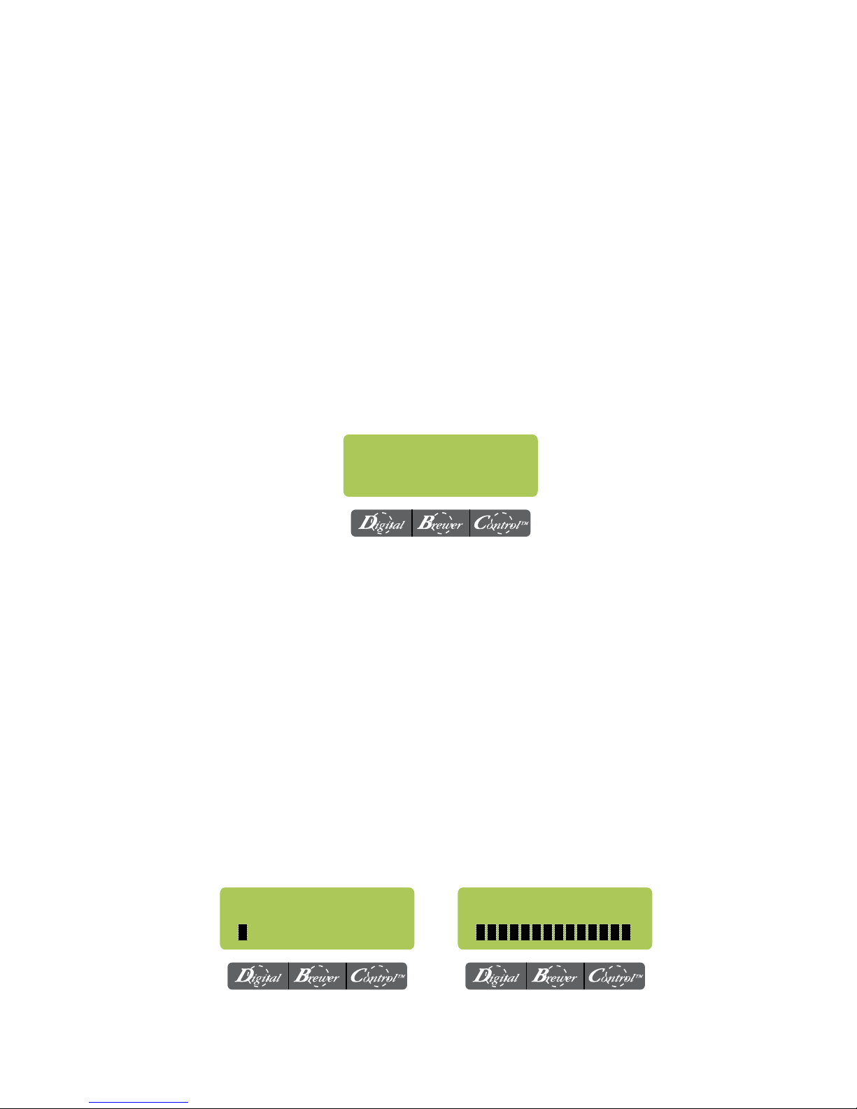
BREW METER:
This function allows the operator to adjust the brew strength/extraction time. Setting #1 will produce
a non-pulsed brew cycle and the highest (#14) will give you the longest time (utilizing pulse brew).
Procedure:
1. Press and hold the right hidden switch until the display reads "BrewWIZARD" and release.
2. The display will then read: "BREW OZ: xx.x"
3. Press and release the right hidden switch until the display reads "BREW METER"
4. Press (-) to decrease the amount, or (+) to increase. (Range: 1 - 14)
5. When finished, press and release the right hidden switch. This will take you to the next screen,
or press and release the "ENABLE BREW ON/OFF" switch to return to the main screen.
Weakest (Shortest) Strongest (Longest)
BREW METER 1
- +
NOTE: This will overwrite settings in "PULSE BREW"
Page 13
BREW METER 14
- +
39130.4 040212
Page 14
ADJUSTMENTS & OPTIONAL SETTINGS (CONT.)
SPRAY OZ/M: 25.0
(-) DONE (+)
CALIBRATE FLOW ?
NO YES
CONTAINER READY ?
QUIT YES
View or enter the actual flow rate coming out of the sprayhead.
This is used to tell the internal controller how fast the water
is flowing. Use the "CALIBRATE FLOW" screen to obtain the
most current flow rate.
Range: (3.0 to 75.0 oz) or (100 to 2200ml)
This function provides a 60 second test mode to capture water from
each sprayhead. This measurement will then give you the numbers
to enter into the "SPRAY OZ/M: xx" screen (next) NOTE: Should be
performed after deliming and/or changing sprayhead.
(Will not display when "BrewLogic" is enabled)
This function allows the operator to test and enter the actual flow
rate of the sprayhead(s) for each side of the brewer by dispensing
each separately for one minute. The volumes are then entered into
the brewer.
WARNING: The sprayhead(s) must be installed before proceeding!
CALIBRATE SPRAY
PRESS BREW START
ENTER OZ 25.0
(-) DONE (+)
NEW SPRAY FLOW:
25.0 OZ/M
Procedure to calibrate the sprayhead flow rate:
1. Place a container, accurately graduated with a minimum capacity
of 60 ounces, under the funnel.
2. Press and hold the right hidden switch until the display reads
"AXIOM - VERSION #.#". Press and release the right hidden switch
until the display reads "CALIBRATE FLOW ?"
3. Select "YES". The display should read "CONTAINER READY?" If
container is under the funnel, select "YES".
4. The display should read "CALIBRATE SPRAY". Press and release
the "BREW" switch to begin the sprayhead flow for calibration. The
display should read "CALIBRATE SPRAY...60 SEC TO FINISH. The
60-second timer on the display will count down to zero. When
the counter reaches zero, the display will change to "ENTER OZ
25.0"
5. Measure the amount of water in the container and use (-) and (+)
to adjust the display to the amount in the container. Then select
"DONE"
6. The display should now read "NEW SPRAY FLOW" along with the
correct flow rate of the sprayhead. After about 5 seconds, the
display will return to the "CALIBRATE FLOW" screen.
7. To exit the "CALIBRATE FLOW" function and advance to the next
screen, select NO. To exit programming and return to the MAIN
SCREEN, press "ENABLE BREW ON/OFF" switch.
8. (TWINS) Repeat steps 1-7 to calibrate the other side.
Page 14
39130.4 040212
Page 15

ADJUSTMENTS & OPTIONAL SETTINGS (CONT.)
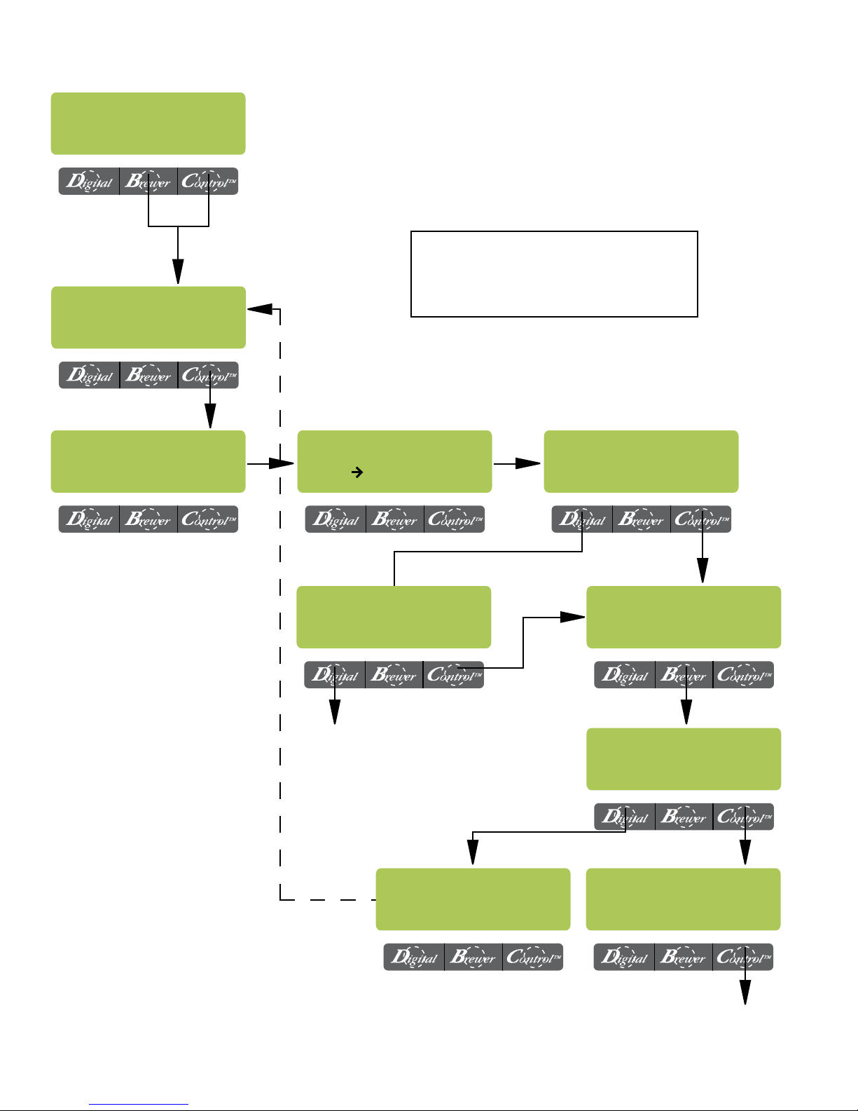
ENABLE ADS
This function allows the operator to choose whether or not to display an advertising message. An
ad can be saved to the brewer by writing the ad
using the programming commands. This message
will be displayed when the brewer is idle.
Procedure to Enable/Disable Ads:
1. Press and hold the right hidden switch until
the display reads "BrewWIZARD" then release.
Press and release the right hidden switch until
the display reads "ENABLE ADS ?". The "YES"
or "NO" will be flashing to indicate the current
selection.
2. Press and release the "NO" switch to disable
this function, or:
3. Press and release the "YES" switch to enable
this function.
4. When finished, press and release "DONE" to
save the new setting and advance to the next
function screen.
5. If "NO" was selected, the display should now
read "ENTER SERVICE #?". To exit programming and return to the MAIN SCREEN, press
and release the "ENABLE BREW ON/OFF"
switch.
6. If "YES" was selected, the display should now
read "NEW AD?". This screen allows you to
write a new ad.
7. The display should now read "2 LINES 16
CHARS AVAILABLE", and then "SCROL
THRU ALPHA, NEXT -> NEXT LETTER", and
then "WRITE TOP LINE?". The ad can be up
to 32 characters long, 16 per line. The ad will
be written in two steps, first the top line, then
the bottom line.
9. To write the top line of a new ad, press and
release "YES". To skip the top line and only
write a bottom line, press and release "NO"
and proceed to step 13. To exit programming and return to the MAIN SCREEN, press
and release the "ENABLE BREW ON/OFF"
switch.
10. The display will now read "A" with a flashing
cursor below it. Press and hold the "SCROLL"
switch to scroll through the alphabet and avail-
able characters. When the desired character
is shown on the display, press and release
"NEXT" to move to the next character in the
top line.
11. Repeat step 10 until the top line is complete.
12. Press and release "DONE". The display should
now read "WRITE BTM LINE?".
13. To write the bottom line of the new ad, press
and release "YES".
14. To skip the bottom line, press and release
"NO".
a. If neither a top nor bottom line was writ-
ten, the display should now read "ENTER
SERVICE #?".
b. If only a top line was written, the ad will
be displayed followed by "SAVE?" Proceed to
step 18.
15. The display will now read A with a flashing
cursor below it. Press and hold the "SCROLL"
switch to scroll through the alphabet and available characters. When the desired character
is shown on the display, press and release
"NEXT" to move to the next character in the
bottom line.
16. Repeat step 15 until the bottom line is complete.
17. Press and release "DONE". The display will
now show the written ad, and then "SAVE?"
18. To cancel saving the ad, press and release
"NO". The display should now read "ADVERTISEMENT NOT SAVED!" and then will return
to the "NEW AD" screen. To exit programming and return to the MAIN SCREEN, press
and release the "ENABLE BREW ON/OFF"
switch.
19. To correct or edit the ad, press and release
"EDIT". The display should now read "WRITE
TOP LINE?" Repeat steps 10 though 17.
20. To save the ad as it is shown, press and release "YES". The display should now read
"ADVERTISEMENT SETUP COMPLETE",
and then "ENTER SERVICE #?". To exit programming and return to the MAIN SCREEN,
press and release the "ENABLE BREW ON/
OFF" switch.
Page 15
39130.4 040212
Page 16
ADJUSTMENTS & OPTIONAL SETTINGS (CONT.)
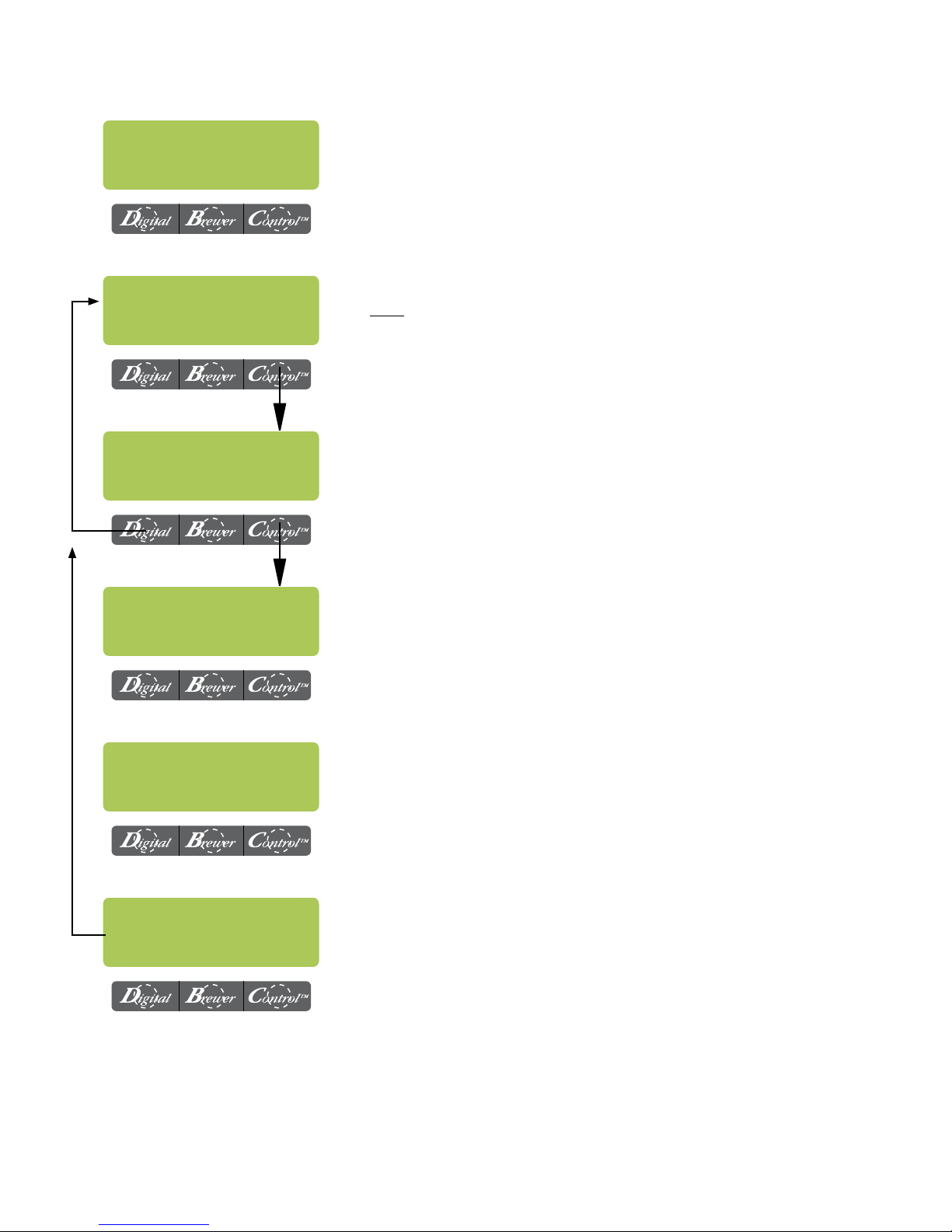
ENABLE ADS ?
NO DONE YES
NEW AD ?
NO YES
NOTE: The available characters are:
A through Z
0 through 9
! " # $ % & ' ( ) * + , - . / : ; < = > ? @
2 LINES 16 CHARS
AVAILABLE
SCROL THRU ALPHA
NEXT NEXT LETTER
WRITE BTM LINE ?
NO YES
ENTER SERVICE #?
WRITE TOP LINE ?
NO YES
A
SCROLL DONE NEXT
SAVE ?
NO EDIT YES
ADVERTISEMENT
NOT SAVED !
Page 16
ADVERTISEMENT
SETUP COMPLETE
ENTER SERVICE #?
39130.4 040212
Page 17
ADJUSTMENTS & OPTIONAL SETTINGS (CONT.)
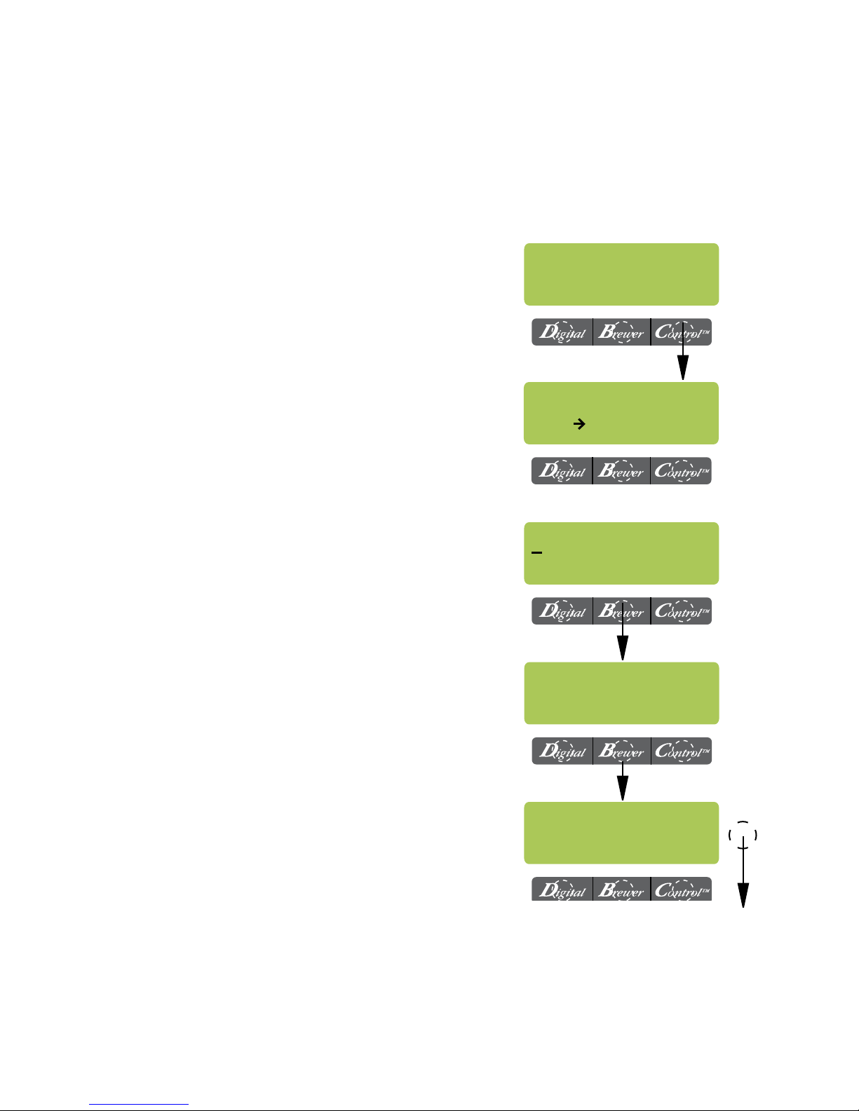
SERVICE NUMBER
This function allows the operator to enter in the
telephone number to call if service is needed. The
service number will be displayed anytime there
is a fault message displayed.
Procedure to enter the service number:
1. Press and hold the right hidden switch until
the display reads "BrewWIZARD" then release.
Press and release the right hidden switch until
the display reads: "ENTER SERVICE #?"
2. Press and release "YES" switch. The display
will now read "SCROL THRU #'S NEXT - >
NEXT NUMBER", followed by "SCROLL
DONE NEXT".
3. Press the "SCROLL" switch to increment the
number. When the desired number is shown,
press and release the "NEXT" switch to move
to the next digit in the phone number.
4. Repeat Step 3 until the entire number is entered.
5. Press and release the "DONE" switch. The
display will now read "EXITING BrewWIZARD"
and then "ENTER PASSWORD".
ENTER SERVICE #?
NO YES
SCROL THRU #'s
NEXT NEXT NUMBER
SCROLL DONE NEXT
PROGRAMMING FUNCTIONS - LEVEL 2
ENTER PASSWORD
This function allows the operator to enter a 3
digit number to access LEVEL 2. If no number
has been pre programmed (0 0 0), then access
is allowed by pressing and releasing the right
hidden switch.
Procedure to enter the "PASSWORD":
1. Press and release the "Digital" switch to increment the first digit.
2. Press and release the "Brewer" switch to
increment the second digit.
3. Press and release the "Control" switch to
increment the third digit.
4. Press and release the right hidden switch. If
the correct password was entered, the display
will now read "SET PASSWORD". If the wrong
password was entered, the unit will revert back
to the main screen.
EXITING
BrewWIZARD
ENTER PASSWORD
0 0 0
Page 17
39130.4 040212
Page 18
ADJUSTMENTS & OPTIONAL SETTINGS (CONT.)
PROGRAMMING FUNCTIONS - LEVEL 2 (cont.)
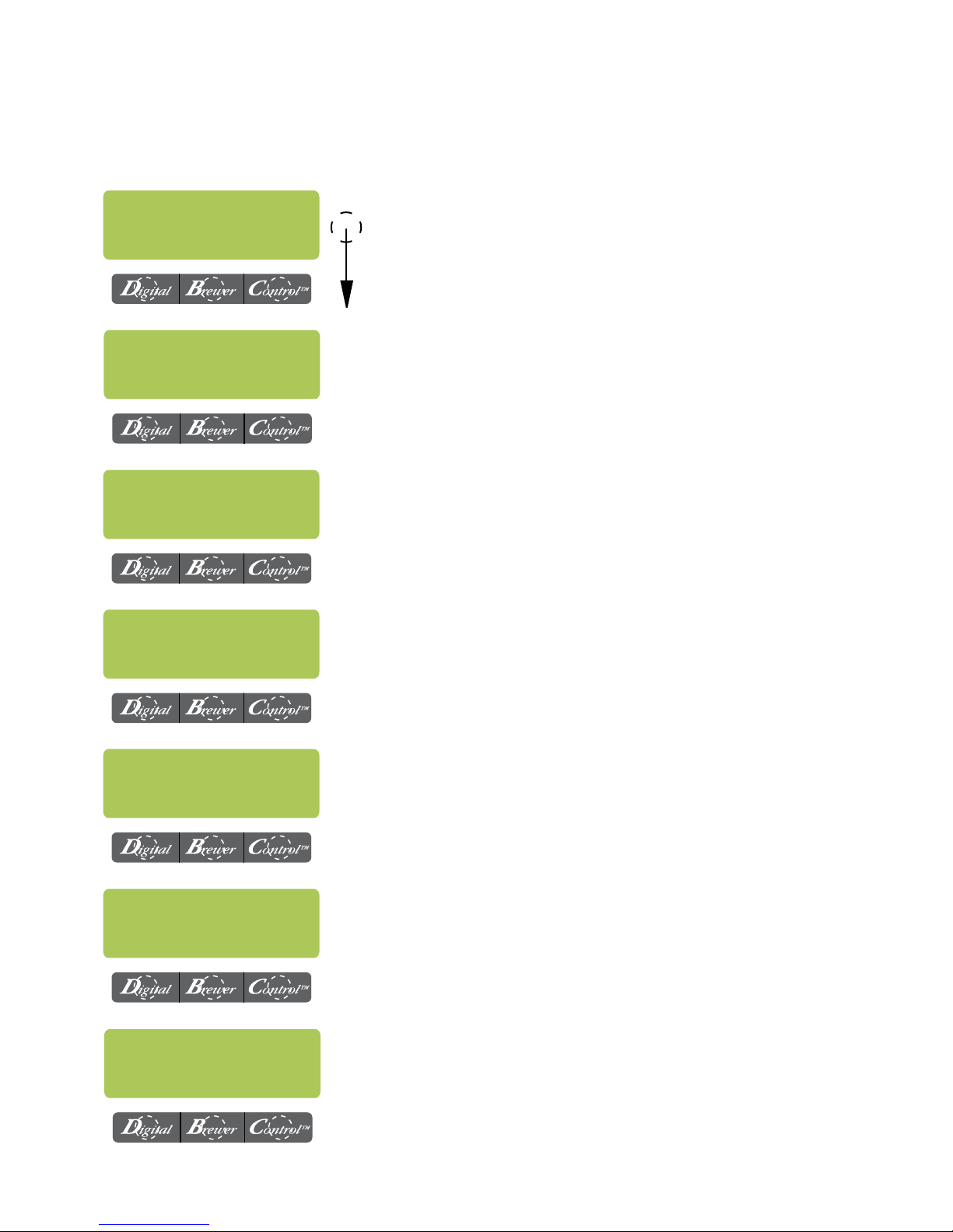
NOTE: Access to the remaining functions in LEVEL 2 is intended for trained service personnel only.
More in depth information can be found in the Axiom Service Manual 39132.0000
SET PASSWORD
0 0 0
SET LANGUAGE
NO YES
UNITS
METRIC DONE ENG
SET TEMP: 200°
(-) DONE (+)
Any 3 digit number may be programmed to prevent unauthorized access of LEVEL 2. BE CAREFUL TO USE A CODE YOU WILL
REMEMBER!
Choose between English or Spanish. After selecting "YES",
press either ( + ) or ( - ) to select, then choose "YES" again
when asked, "ARE YOU SURE?"
Choose between English or Metric units. Display will read:
"CHANGING UNITS WILL CAUSE" "ALL SETUP INFO TO BE
LOST" "ARE YOU SURE?" "NO YES". NOTE: If the brewer
is set for Metric Units, displays will be different. (ex: Brew oz
will become Brew milliliters, ° F will be ° C).
Adjusts brew tank temperature.
RANGE: (185 to 205° F) or (85 to 96° C)
SET READY: 195°
(-) DONE (+)
ENTER ASSET # ?
NO YES
SET PULSE BREW ?
NO YES
This function sets the minimum temperature allowable to start
a brew cycle. Range: (2° to 20° F) or (2° to 10° C) below the set
temperature. The water must be at the "READY" temperature
or higher for the display to indicate "READY TO BREW".
This function allows the you to enter in an optional asset number. This can be useful for tracking the usage or service of an
individual machine within a group.
This function allows the sprayhead to “pulse” on and off during a brew cycle. These times can be set two different ways.
The first is by setting the total brew time in the "EASY PULSE
BREW" screen. The other option allows the actual times to be
entered in the "MANUAL PULSE BREW" screen.
NOTE: This will overwrite settings in "BREW METER".
Page 18
39130.4 040212
Page 19
ADJUSTMENTS & OPTIONAL SETTINGS (CONT.)
PROGRAMMING FUNCTIONS - LEVEL 2 (cont.)
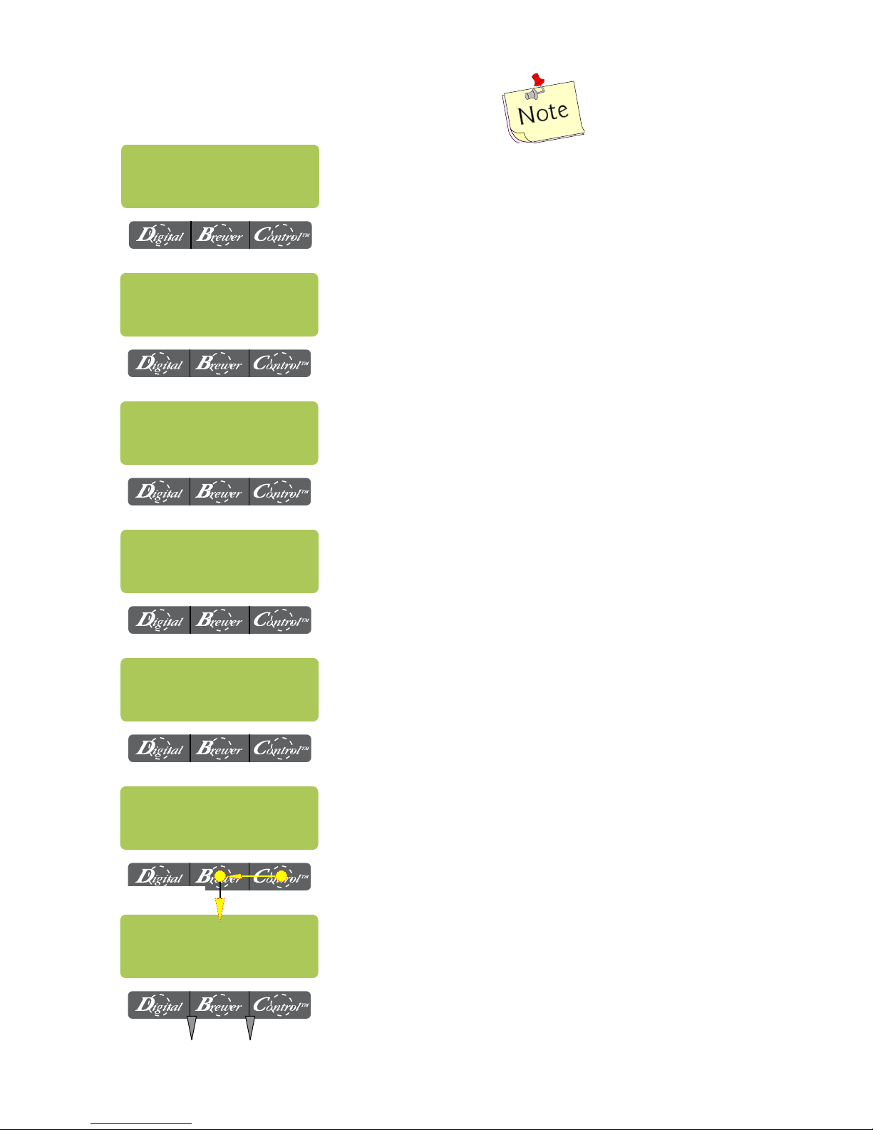
"EASY PULSE BREW" times:
Min: Base brew time + 40 seconds
Max: Base brew time + 3:00 minutes
DRIP TIME 1:00
(-) DONE (+)
ENABLE CLEAN
NO DONE YES
Enabl EnergySavr
NO DONE YES
0 REFILL 155
(-) DONE (+)
Adjusts the DRIP TIME (time from end of sprayhead flow to
when liquid stops dripping from the funnel). When the brew
cycle is complete, the display will show "DRIPPING" and will
countdown the time until the funnel empties.
RANGE: "OFF" or 0:05 to 4:00 minutes
Set the time before a cleaning alert will be displayed.
RANGE: 1 to 30 days
Enables the mode function and sets the idle time. Then choose
to have the tank heater(s) turn off, or reduce the tank temp to
(140° F) or (60° C) once the set idle time has expired.
Range: 0.5 - 24.0 hrs
Adjusts the sensitivity of the refill circuit. Water in different
geographical locations can have different conductivities. Make
sure the water in the tank is touching the refill probe. NOTE:
Always make sure that the # on the right is larger than the #
on the left when water is contacting the tank refill probe.
ENABLE BrewLOGIC
NO DONE YES
ENABLE BrewLOGIC
NO DONE YES
Go to
SPRAY OZ/M:
PLACE BREWER IN
FINAL LOCATION
The BrewLogic system allows the brewer to be calibrated to
high mineral locations and compensate as deposits build up
internally. Press YES, then press DONE. Follow the prompts.
Pertains only to software version 1.07 & above!
The BrewLogic system allows the brewer to be calibrated to
high mineral locations and compensate as deposits build up
internally. Press YES, then press DONE. Follow the prompts.
Select a sturdy, level location.
Brewer must not be bumped during calibration!
(CONT.)
Page 19
39130.4 040212
Page 20
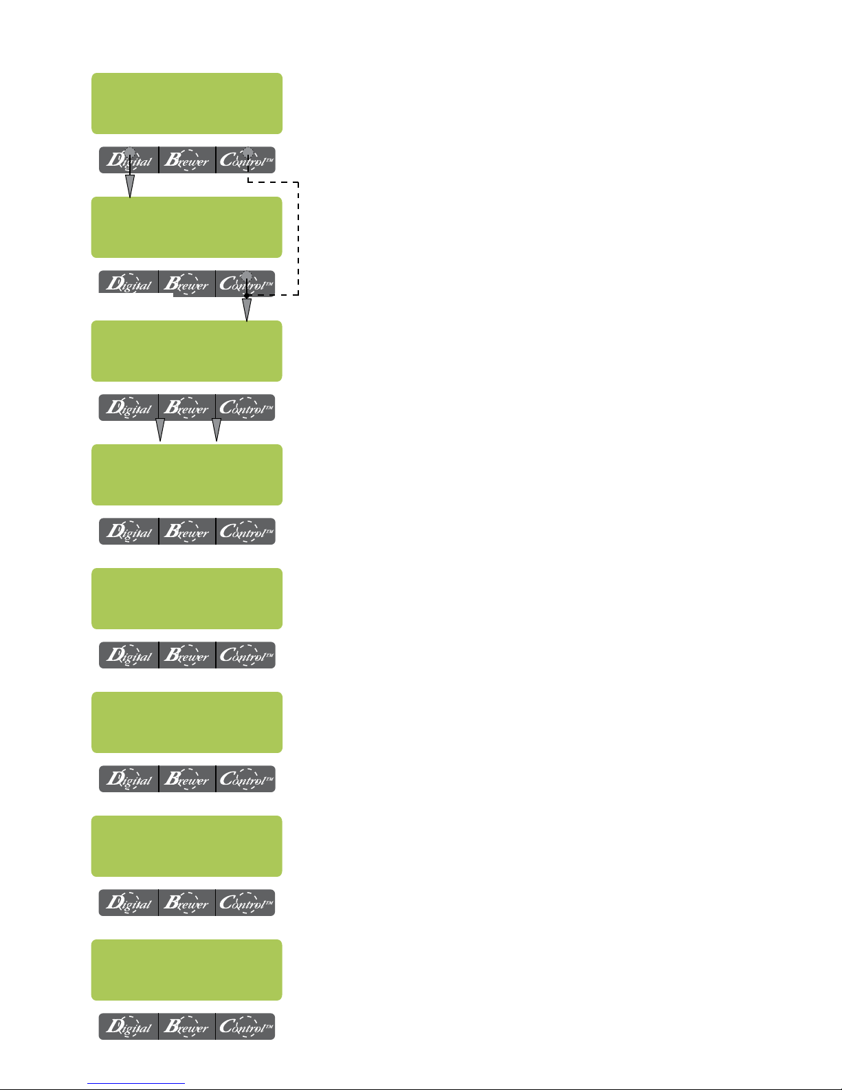
ADJUSTMENTS & OPTIONAL SETTINGS (CONT.)
CALIBRATE NOW?
NO YES
Select YES for calibration. Selecting NO warns of accuracy
risk
ACCURACY RISK!!!
OK CAL.
Go to CAL
LP1-LP2
TOO HOT-WILL
COOL TANK NOW
PRESS BREW WHEN
CONTAINER READY
COOLING TANK
PLEASE WAIT
Select CAL. to start calibration procedure. Selecting OK will
skip to level probe calibration screen.
Automatically checks to see if tank temperature is between
130°-170°F (54°-76°C)
Verify brew funnel and decanter/thermal server (depending on
which model you have) are in place. Then press the "BREW
START" button.
Message will be displayed while dispense is being performed.
Tank heaters are turned off and the unit will dispense for ~1
minute to cool tank temperature.
BREW COUNTERS ?
NO YES
SERVICE TOOLS ?
NO YES
FACTORY DEFAULTS
NO YES
Tracks the total number of brew cycles completed. There is one
reset-able counter, and one life counter that is not reset-able
Allows the testing of individual components and the ability to
check the membrane switches for proper function. (Diagnostic
tool for troubleshooting purposes only)
Reset ALL of the previously entered brew settings, ad message, calibrations, etc. Factory-set default values will replace
ALL previous settings.
NOTE: Items not affected; Service #, Password, Language,
Units, Asset #, Counters and Serial Number.
Page 20
39130.4 040212
 Loading...