


AFPO-2
F
L
AV
O
R
IN
P
U
T
1
2
W
A
T
E
R
IN
P
U
T
RE
FI
LL
M
AI
N
PO
W
E
R
2 1
1
2
3
3
3
FLA
V
O
R
OU
T
P
U
T
F
LA
VO
R
O
U
T
PU
T
WA
T
E
R
OU
T
PU
T
FL
A
V
O
R
O
U
T
P
U
T
W
A
T
ER
O
U
T
P
U
T
W
AT
ER
O
U
T
PU
T
F
LA
VO
R
IN
P
UT
1
2
W
A
T
E
R
IN
P
U
T
FL
A
V
OR
O
U
T
P
U
T
FL
A
V
O
R
OU
T
PU
T
W
A
T
E
R
O
U
T
P
U
T
W
A
T
E
R
OU
T
PU
T
RE
F
I
LL
MA
I
N
PO
W
ER
2 1
1
2
AFPO-2 SL
AFPO-3
AFPO-3 SL
SERVICE & REPAIR MANUAL
BUNN-O-MATIC CORPORATION
PHONE: (217) 529-6601 FAX: (217) 529-6644
SPRINGFIELD, ILLINOIS 62708-3227
POST OFFICE BOX 3227
41093.0000A 04/08 ©2008 Bunn-O-Matic Corporation

BUNN-O-MATIC COMMERCIAL PRODUCT WARRANTY
Bunn-O-Matic Corp. (“BUNN”) warrants equipment manufactured by it as follows:
1) All equipment other than as specified below: 2 years parts and 1 year labor.
2) Electronic circuit and/or control boards: parts and labor for 3 years.
3) Compressors on refrigeration equipment: 5 years parts and 1 year labor.
4) Grinding burrs on coffee grinding equipment to grind coffee to meet original factory screen sieve analysis:
parts and labor for 3 years or 30,000 pounds of coffee, whichever comes first.
These warranty periods run from the date of installation BUNN warrants that the equipment manufactured by
it will be commercially free of defects in material and workmanship existing at the time of manufacture and
appearing within the applicable warranty period. This warranty does not apply to any equipment, component or
part that was not manufactured by BUNN or that, in BUNN’s judgment, has been affected by misuse, neglect,
alteration, improper installation or operation, improper maintenance or repair, damage or casualty. This warranty is
conditioned on the Buyer 1) giving BUNN prompt notice of any claim to be made under this warranty by telephone
at (217) 529-6601 or by writing to Post Office Box 3227, Springfield, Illinois 62708-3227; 2) if requested by
BUNN, shipping the defective equipment prepaid to an authorized BUNN service location; and 3) receiving prior
authorization from BUNN that the defective equipment is under warranty.
THE FOREGOING WARRANTY IS EXCLUSIVE AND IS IN LIEU OF ANY OTHER WARRANTY, WRITTEN OR
ORAL, EXPRESS OR IMPLIED, INCLUDING, BUT NOT LIMITED TO, ANY IMPLIED WARRANTY OF EITHER
MERCHANTABILITY OR FITNESS FOR A PARTICULAR PURPOSE. The agents, dealers or employees of BUNN
are not authorized to make modifications to this warranty or to make additional warranties that are binding on
BUNN. Accordingly, statements by such individuals, whether oral or written, do not constitute warranties and
should not be relied upon.
If BUNN determines in its sole discretion that the equipment does not conform to the warranty, BUNN, at its
exclusive option while the equipment is under warranty, shall either 1) provide at no charge replacement parts
and/or labor (during the applicable parts and labor warranty periods specified above) to repair the defective
components, provided that this repair is done by a BUNN Authorized Service Representative; or 2) shall replace
the equipment or refund the purchase price for the equipment.
THE BUYER’S REMEDY AGAINST BUNN FOR THE BREACH OF ANY OBLIGATION ARISING OUT OF THE SALE OF
THIS EQUIPMENT, WHETHER DERIVED FROM WARRANTY OR OTHERWISE, SHALL BE LIMITED, AT BUNN’S
SOLE OPTION AS SPECIFIED HEREIN, TO REPAIR, REPLACEMENT OR REFUND.
In no event shall BUNN be liable for any other damage or loss, including, but not limited to, lost profits, lost sales,
loss of use of equipment, claims of Buyer’s customers, cost of capital, cost of down time, cost of substitute
equipment, facilities or services, or any other special, incidental or consequential damages.
BrewWISE, BUNN Gourmet Ice, BUNN Pour-O-Matic, BUNN, Bunn-OMatic, Bunn-O-Matic, BUNNlink, BUNNserve, BUNN
Espress, DBC, Dr. Brew, Dual, EasyClear, EasyGard, Easy Pour, FlavorGard, Gourmet Ice, Gourmet Juice, High Intensity,
IMIX, Infusion Series, Legendary for Quality, The Mark of Quality in Beverage Equipment Worldwide, My Café, PowerLogic, Safety-Fresh, Scale-Pro, Single, Smart Funnel, Smart Hopper, SmartWAVE, Soft Heat, SplashGard, System III,
ThermoFresh, 392, AXIOM, Beverage Profit Calculator, Beverage Bar Creator, BrewLOGIC, BrewMETER, BrewWIZARD,
BUNNSERVE, BUNNsource, Coffee At Its Best, Cool Froth, Digital Brewer Control, Intellisteam, Nothing Brews Like a
BUNN, Pouring Profits, Pulse Wave, Quality Beverage Equipment Worldwide, , Signature Series, Silver Series, Smart Heat,
Tea At Its Best, The Horizontal Red Line, Titan, Ultra, are either trademarks or registered trademarks of Bunn-O-Matic
Corporation.
2
41093 041108

CONTENTS
User Notices ..............................................................................................................................3
Preventive Maintenance
Cleaning ..................................................................................................................................... 4
Adjustments ...............................................................................................................................4
Operating Controls .....................................................................................................................6
Troubleshooting .........................................................................................................................7
Service ......................................................................................................................................9
Circuit Board ............................................................................................................................ 10
Fuse & Fuse Holder .................................................................................................................. 11
Main ON/OFF Switch ................................................................................................................ 12
Probe LOW/OFF/HIGH Switches ............................................................................................... 13
Pump (Flavor) Start Switches .................................................................................................. 14
Refill ON/OFF Switches ........................................................................................................... 15
Solenoid ................................................................................................................................... 16
Solenoid (Water) Start Switches .............................................................................................. 17
Test/Operate Switch ................................................................................................................. 18
Vacuum/Supply Pump Assembly ............................................................................................. 19
Vacuum Switches .................................................................................................................... 21
Piping Diagram ........................................................................................................................ 22
Wiring Diagrams ...................................................................................................................... 23
USER NOTICES
All notices on the equipment are written for your protection. All notices are to be kept in good condition. Replace
any unreadable or damaged labels.
3
41093 040408

CLEANING
RECOMMENDED WEEKLY CLEANING:
This should be done in conjunction with the recommended weekly cleaning of your machine. The Hoppers must
be empty before starting.
1. Prepare a 1 gallon cleaning solution consisting of 1 gallon of hot water and a sanitizing cleaner which contains
3-5% chlorine based sanitizer. Mix per manufacturers instructions
2. Remove connectors from each concentrate container and place them directly into the cleaning solution.
3. Energize each refill station and allow the cleaning solution to pump through the system into the hoppers. The
cleaning procedure should remove the color stains from the tubing. If not, prepare another gallon of cleaning
solution and repeat.
4. After the cleaning solution has been pumped into the hoppers, rinse the cleaning solution container with hot
water.
5. Fill the cleaning solution container with hot water. Energize each refill station and rinse thoroughly. The amount
of clean hot rinse water should equal the amount of cleaning solution pumped through the system.
6. Empty the hoppers of your machine and follow the recommended cleaning instructions.
NOTE: The hoses should be checked monthly for deterioration, cracks and possible discoloration from some
concentrates. Replace the tubing when necessary.
MIX RATIO ADJUSTMENTS
1. Remove the top access panel.
2. Connect the test hose to the “WATER OUTPUT” to be adjusted.
3. Connect the provided hose (or other suitable water hose) to the “WATER INPUT”.
4. Ensure water regulator is set at 20 psi(137.9 kPa). Press the “TEST OUTPUT” switch and while water is
flowing from the test hose, check that the gauge reads 20.
5. Place a one-cup container under the test hose. Press the “TEST OUTPUT” switch, and carefully measure and
note the elapsed time from when water first flows form the test hose to when one cup of water has been
dispensed. Hoses and tubing should be primed and free of substantial air spaces and/or bubbles prior to
calibration.
6. Compare results with chart or formula below.
7. If the time observed is too short or long, turn the needle valve clockwise or counterclockwise, respectively,
a little at a time. Repeat from the preceding step until correct.
4
41093 040408

1
2
2 1
1
2
3
3
3
MIX RATIO ADJUSTMENTS(cont.)
Mix ratio (water/flavor) Time for FLAVOR OUTPUT (1/2 cup) Time for WATER OUTPUT (1 cup)
1+1 assume 20 sec. or obtain time per note below 40 sec. or 2 times flavor output time
2+1 assume 20 sec. or obtain time per note below 20 sec. or equal to flavor output time
3+1 assume 20 sec. or obtain time per note below 13.3 sec. or 0.67 times flavor output time
4+1(see below) assume 20 sec. or obtain time per note below 10 sec. or 0.5 times flavor output time
5+1 assume 20 sec. or obtain time per note below 8 sec. or 0.4 times flavor output time
6+1 assume 20 sec. or obtain time per note below 6.7 sec. or 0.33 times flavor output time
NOTE: For a typical adjustment, the time for flavor output in the center column above is assumed to be 20
seconds. A more specific flavor pump output time may be obtained prior to adjustment of the needle valve.
To do so, connect the flavor to be tested to the “FLAVOR INPUT”, and the test hose to the corresponding
“FLAVOR OUTPUT” (make no connection to the “WATER INPUT”). With a one-cup container under the
test hose press the corresponding “TEST OUTPUT” switch, and carefully measure and note the elapsed
time from when the product first flows from the test hose to when one-half cup of the product has been
dispensed. This value may then be used in the formula below. Following flavor pump output measurement,
disconnect the flavor line from the “FLAVOR INPUT” and purge remaining product from the line.
Formula for setting mix ratio: To obtain the time for dispensing 1 cup of water, divide the time it
takes to dispense one-half cup of product by the first number in the mix ratio and then multiply
the result by two.
Example: W=2(F/X) Where W is the time it should take to dispense one cup of water, it took F
seconds (20 here) to dispense 1/2 cup of flavor concentrate, we desire a mix ratio X of 4+1 (X
will be the first number in the mix ratio, 4).
Therefore: W = 2/(20/4)
W = 2/5
W = 10 seconds
So if it took 20 seconds to dispense one-half cup of flavor concentrate, and a mix ratio of 4 to 1
is required, the needle valve should be adjusted to dispense 1 cup of water in 10 seconds.
NOTE: Hoses and tubing should be primed and free of substantial air spaces and/or bubbles prior
to calibration.
NEEDLE VALVE
P1521
5
41093 040408

FLAVOR
INPUT
1
2
WATER
INPUT
REFILL
MAIN
POWER
1
1
2
3
FLAVOR
OPERATING CONTROLS
C
B
A
P1949
A. MAIN POWER ON/OFF
The main power ON/OFF switch is located on the right of the front panel just above the power cord.
B. REFILL CIRCUIT ON/OFF
The refill circuit ON/OFF switches are located on the right of the front panel just above the main power switch.
These allow each circuit to operate independently.
C. TEST/OPERATE
The TEST/OPERATE switch is located inside the auto-fill
box just below the top access cover. For setting flow
rates and mix ratios for flavors, place the TEST/OPERATE switch in the “TEST” position. This allows the op-
D
erator to run the water and flavor lines for each circuit
depending on the requirements for the flavor recipe.
D. PROBE CONTROL BOX LOW/OFF/HIGH
On models equipped with a dual level probe, there is a
LOW/OFF/HIGH switch located at the probe control box
on the hopper. The “OFF” position allows the operator
to disable the probe for that hopper only. THE “LOW”
and “HIGH” positions allow the operator to select the
level of product desired for that hopper.
P1951
6
41093 040408

TROUBLESHOOTING
A troubleshooting guide is provided to suggest probable causes and remedies for the most likely problems
encountered. If the problem remains after exhausting the troubleshooting steps, contact the Bunn-O-Matic
Technical Service Department.
• Inspection,testing,andrepairofelectricalequipmentshouldbeperformedonlybyqualiedserviceperson-
nel.
• Allelectronic components have 120 volt ac andlowvoltagedcpotentialontheirterminals.Shortingof
terminals or the application of external voltages may result in board failure.
• Intermittentoperationofelectroniccircuitboardsisunlikely.Boardfailurewillnormallybepermanent.If
an intermittent condition is encountered, the cause will likely be a switch contact or a loose connection at a
terminal or crimp.
• Solenoidremovalrequiresinterruptingthewatersupplytothevalve.Damagemayresultifsolenoidsare
energized for more than ten minutes without a supply of water.
• Theuseoftwowrenchesisrecommendedwheneverplumbingttingsaretightenedorloosened.Thiswill
help to avoid twists and kinks in the tubing.
• Makecertainthatallplumbingconnectionsaresealedandelectricalconnectionstightandisolated.
• Keepawayfromcombustibles.
WARNING – • Exerciseextremecautionwhenservicingelectricalequipment.
• Unplugthedispenserwhenservicing,exceptwhenelectricaltestsarespecied.
• Followrecommendedserviceprocedures
• Replaceallprotectiveshieldsorsafetynotices
PROBLEM
Product will not dispense
PROBABLE CAUSE
1. No water
2. No power or incorrect voltage to
the dispenser
3. Signal cable unplugged
4. Hopper is full
5. Fuse and fuse holder
REMEDY
Water lines and valves to the dispenser must be open.
(A1) Check the outlet for 120 volts
on two wire 120 volt dispensers.
(A2) Check the outlet for 200 volts
or 240 volts ac for two wire 200 volt
or 240 volt dispensers.
(A3) Check the outlet for 230 volts
on two wire 230 volt dispensers.
(B) Check circuit breakers or fuses.
Signal cable must be plugged in.
Product must not be touching probes
to fill.
Refer to Service - Fuse and Fuse
Holder for test procedures. See
page 12
7
41093 040408

TROUBLESHOOTING (cont.)
PROBLEM
PROBABLE CAUSE
REMEDY
Product will not dispense (cont.)
6. Main ON/OFF switch
7. Probe box LOW/OFF/HIGH switches
8. Circuit board
9. Vacuum switch
10. Vacuum/Supply pump
11. Pump (flavor) start switches
Refer to Service - Main ON/OFF
Switch for testing procedure. See
page 13
Refer to Service - Probe system.
See page 14
Refer to Service - Circuit Board for
testing procedures. See page 11
Refer to Service - Vacuum switch for
testing procedures. See page 22
Refer to Service - Vacuum/Supply
pump for testing procedures. See
page 20
Refer to Service - Pump (flavor)
start switches for test procedures.
See page 15
Incorrect mix ratio
1. No water
Water lines and valves to the dispenser must be open.
2. Needle valve
Refer to Setup - Mix Ratio Adjustments for adjustment. See page 5
3. Solenoids
Refer to Service - Solenoids for test
procedures. See page 17
Motor thermal cutout (motor stops
running)
1. Motor overheat
The thermal switch will reset, but
requires up to 30 minutes of cooling
time. See NOTE below
NOTE: This refill unit should not be used to initially fill the hopper. Running the motor for extended periods will
trip the thermal switch. The thermal switch will reset, but requires up to 30 minutes of cooling time.
8
41093 040408

FL
A
V
O
R
INPU
T
1
2
WAT
ER
IN
PU
T
R
EF
IL
L
M
AI
N
PO
W
ER
2 1
1
2
3
3
3
F
LA
VOR
O
U
T
PUT
FL
A
V
OR
O
UT
PU
T
W
AT
E
R
O
UT
PU
T
FL
A
VO
R
OU
T
P
UT
WA
TER
OU
T
P
UT
W
AT
ER
O
UT
PU
T
SERVICE
This section provides procedures for testing
and replacing various major components used in this
dispenser should service become necessary. Refer
to Troubleshooting for assistance in determining the
cause of any problem.
WARNING - Inspection, testing, and repair of electrical equipment should be performed only by qualified
service personnel. The dispenser should be unplugged
when servicing, except when electrical tests are required and the test procedure specifically states to
plug in the dispenser.
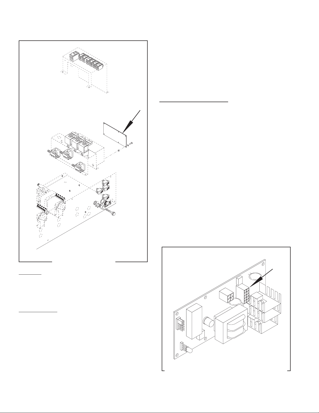
COMPONENT ACCESS
WARNING - Disconnect the dispenser from the power
source before the removal of any panel or the replacement of any component.
All components are accessible by removing the
eight #8-32 screws (five on the front and three on the
rear) securing the main housing to the main mounting
panel and the removal of the four #8-32 nuts securing the pump/solenoid switch panel to the solenoid
mounting bracket. Refer to Fig. 1
FIG. 1 COMPONENT ACCESS
P1521
9
41093 040408
J4
J1
J2
J3
SERVICE
CIRCUIT BOARD
c) 230 volts ac for two wire 230 volt models.
4. Disconnect the dispenser from the power source.
If voltage is present as described, replace the circuit
board.
If voltage is not present as described, refer to the
Wiring Diagrams and check main wiring harness.
Removal and Replacement:
1. Remove the four #8-32 keps nuts securing the
switch mounting bracket. Set aside with the wires
attached.
2. Remove the circuit board shield and set aside for
reassembly.
3. Disconnect the ten pin plug from the main wiring
harness to the circuit board.
4. Remove the six #4-40 screws and spacers securing
the circuit board to the solenoid mounting bracket.
Remove circuit board and discard.
5. Install new circuit board using #4-40 screws and
spacers to secure the circuit board to the solenoid
mounting bracket. The spacers must be between the
solenoid mounting bracket and the circuit board.
6. Place circuit board shield over the circuit board.
7. Install switch panel assembly and secure with four
#8-32 keps nuts.
8. Refer to Fig. 3 for circuit board ten pin connector.
FIG. 2 CIRCUIT BOARD
P1520
Location:
The circuit board is located inside the autofill box,
mounted on the right side of the solenoid mounting
bracket under the switch panel.
Test Procedure:
1. Disconnect the dispenser from the power source.
2. Disconnect the ten pin plug on the main wiring
harness from the connector on the circuit board.
3. Connect the dispenser to the power source. With
a voltmeter, check the voltage across the black
wire(#3) and the white wire (#6). The indication
must be:
a) 120 volts ac for two wire 120 volt models.
FIG. 3 CIRCUIT BOARD CONNECTOR LOCATION
P1528
b) 200 to 240 volts ac for two wire 200 or 240 volt
models.
10
41093 040408
FLAVOR
INPU
T
1
2
WATER
INPUT
REFILL
MAIN
POWER
2 1
1
2
3
3
3
FLAVOR
OUTPUT
FLAVOR
OUTPUT
W
ATER
OUTPUT
F
L
A
VOR
OUT
PUT
W
A
T
ER
OUT
PUT
WATER
OUTPUT
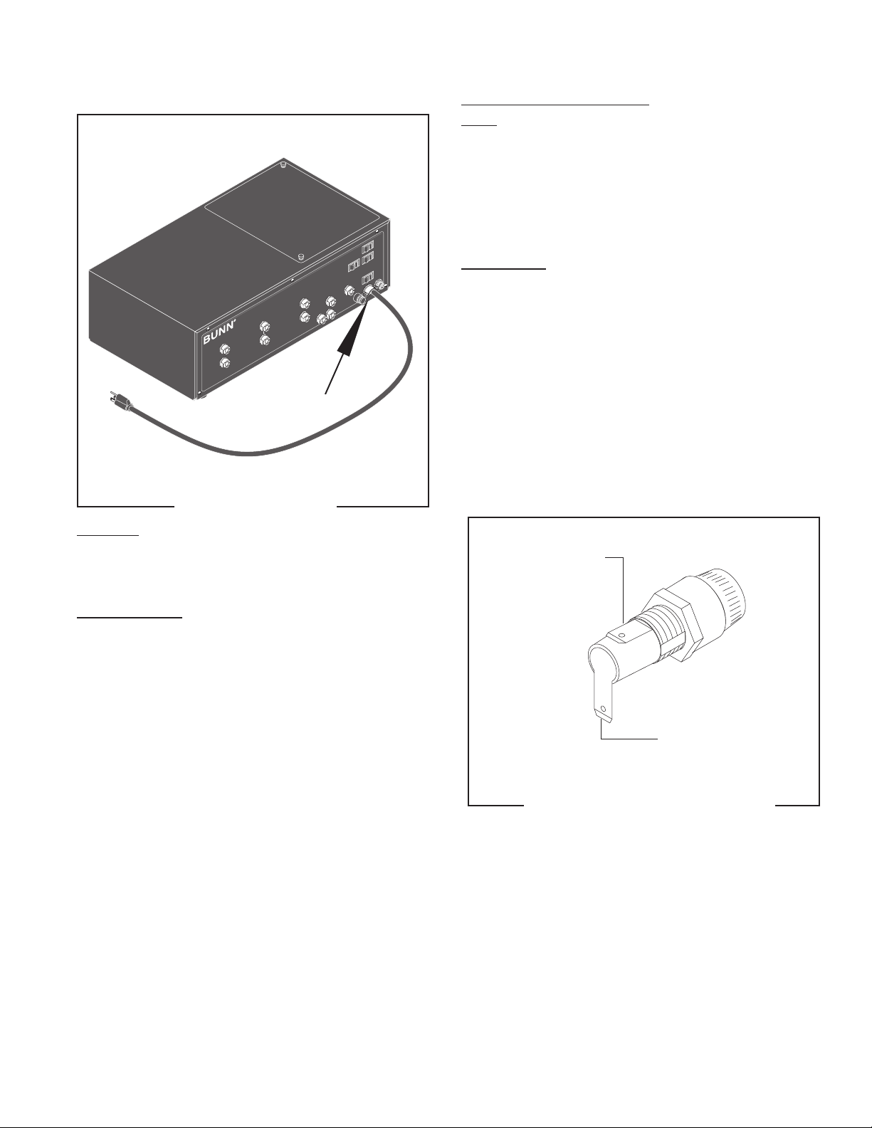
SERVICE
FUSE AND FUSE HOLDER
FIG. 4 FUSE HOLDER
P1516
Location:
The fuse holder is located on the lower right front
of the autofill box just to the left of the power cord.
Removal and Replacement:
Fuse:
1. Remove the cap from the fuse holder.
2. Remove fuse from the fuse holder and inspect. If
blown, discard.
3. Install new 10 amp fuse in the fuse holder.
4. Reinstall fuse holder cap.
Fuse Holder:
1. Disconnect the dispenser from the power source.
2. Disconnect the wires from the rear of the fuse
holder.
3. Remove the nut securing the fuse holder to the
front of the main mounting panel.
4. Push the fuse holder through the hole in the
panel.
5. Install new fuse holder and fuse through the hole
in the panel.
6. Secure the fuse holder to the panel.
7. Refer to Fig. 5 and reconnect the wires.
BLKfromMain
Wiring Harness
Test Procedure:
1. Disconnect the dispenser from the power source.
2. Remove cap and fuse from fuse holder.
3. Remove fuse from the cap.
4. Check for continuity through the fuse.
If continuity is present, reinstall the fuse, the fuse is
operating properly.
If continuity is not present, replace the fuse.
BLKtoMain
ON/OFF Switch
P1331
FIG. 5 FUSE HOLDER TERMINALS
11
41093 040408
FLAVOR
INPU
T
1
2
WATER
INPUT
REFILL
MAIN
POWER
2 1
1
2
3
3
3
FLAVOR
OUTPUT
FLAVOR
OUTPUT
W
ATER
OUTPUT
F
L
A
VOR
OUT
PUT
W
A
T
ER
OUT
PUT
WATER
OUTPUT
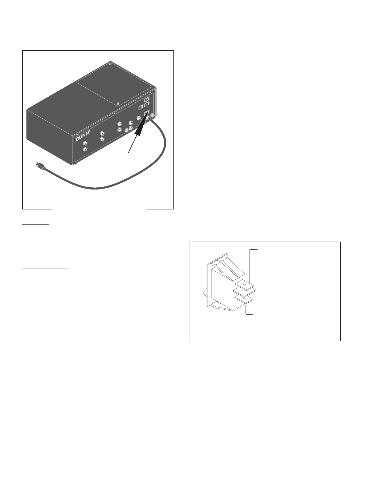
SERVICE (cont.)
MAIN ON/OFF SWITCH
5. Check for continuity across the switch terminals
with the switch in the “ON” position. Continuity
must not be present when the switch is in the
“OFF” position.
If continuity is present as described, reconnect the
wires to the switch terminals.
If continuity is not present as described, replace the
switch.
Removal and Replacement:
1. Remove the wires from the switch terminals.
2. Compress the clips inside the autofill box and
gently push the switch through the opening
3. Push the new switch into the opening and spread
the clips to hold switch in the autofill box.
4. Refer to Fig. 7 when reconnecting the wires.
FIG. 6 MAIN ON/OFF SWITCH
P1516
Location:
The main ON/OFF switch is located on the lower
right front of the autofill box just above the power
cord.
Test Procedure:
1. Disconnect the dispenser from the power
source.
2. Disconnect the black wire from the fuse holder
and the white wire from pump #1.
3. Connect the dispenser to the power source. Check
for voltage across the black wire removed from
the switch and the white wire removed from pump
#1. The indication must be:
a) 120 volts ac for 2 wire 120 volt models.
b) 200 to 240 volts ac for two wire 200 or 240 volt
models.
c) 230 volts ac for two wire 230 volt models.
4. Disconnect the dispenser from the power
source.
If voltage is present as described, proceed to #5.
If voltage is not present as described, refer to the Wiring
Diagrams and check the dispenser wiring harness.
BLKfromFuseHolder
BLKtoSolenoid(Water)
Switch #2 AFPO-2 & 3
FIG. 7 MAIN ON/OFF SWITCH TERMINALS
P1522
12
41093 040408

BU
N
N
SERVICE (cont.)
PROBE SYSTEM
P1523
FIG. 8 PROBE SWITCHES
Location
The probe switches are located on the rear of each
hopper, mounted in the probe housing cover.
Test Procedure
Probe System
1. Disconnect the dispenser from the power
source.
2. With the probe boxes connected to the signal cable,
remove connector from refill box.
3. Place the switch on the probe box in the “HIGH”
position.
Probe Boxes:
1. Disconnect the signal cable from the probe
boxes.
2. Remove probe box from CDS hopper.
3. Place the switch on the probe box in the “HIGH”
position.
4. Check the resistance across the box cable pins,
see Fig. 10.
AFPO-2 & 3
FIG. 10 PROBE BOX CABLE PINS
P1539
5. With the probe box switch in the “LOW” position
check the resistance across the pins, refer to Fig.
10.
6. If readings match the values indicated, the probe
system is functioning properly.
Switch Removal and Replacement:
1. Remove the #6 thread cutting screw securing the
probe housing cover to the probe housing.
2. Remove the wires from the switch terminals.
3. Compress the clips inside the probe box and gently
push the switch through the opening
4. Push the new switch into the opening and spread
the clips to hold switch in the autofill box.
5. Refer to Fig. 11 when reconnecting the wires.
AFPO-2 AFPO-3
P1538
FIG. 9 SIGNAL CABLE PINS
4. Check resistance across pins as shown in Fig. 9.
5. With the probe box switch in “LOW” position check
the resistance across the signal cable pins, see Fig.
9.
6. If readings match values indicated, the probe
system is functioning properly. If not, check the
probe boxes.
13
BLU (HIGH) from Probe
Box Cable
GRN (OFF) from Probe
Box Cable
TAN (LOW) from Probe Box
Cable
FIG. 11 PROBE LOW/OFF/HIGH SWITCH
TERMINALS
P1540
41093 040408

1
2
2 1
1
2
3
3
3
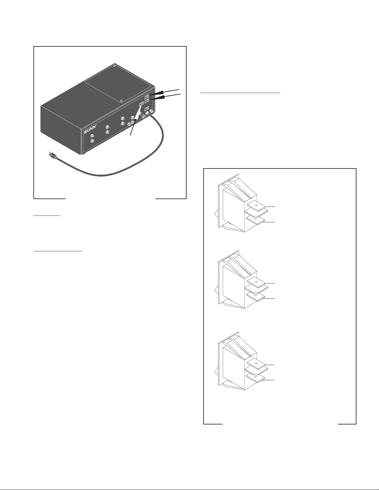
SERVICE (cont.)
PUMP (FLAVOR) ON/OFF SWITCHES
FIG.12 PUMP (FLAVOR) START SWITCHES
Removal and Replacement:
1. Disconnect the dispenser from the power
source.
2. Remove the wires from the switch terminals.
3. Compress the clips inside the autofill box and
gently push the switch through the opening.
4. Push the new switch into the opening and spread
the clips to hold switch in the autofill box.
5. Refer to Fig. 13 when reconnecting the wires.
#1 AFPO-2 & 3
P1521
Location:
The pump (flavor) START switches are located on
the switch mounting plate inside the autofill box on
the right side.
Test Procedure:
1. Disconnect the dispenser from the power
source.
2. Disconnect the wires from the switch to be
tested.
3. Check for continuity across the terminals on the
switch when it is held in the on position. Continuity
must not be present across these terminals in the
released position.
If continuity is present as described, reconnect the
wires to the switch.
If continuity is not present as described, replace the
switch.
BLKfromSolenoidSwitch#1
BLKtoTest/OperateSwitch
RED/BLKtoTest/OperateSwitch
YEL to Pump #1
#2 AFPO-2 & 3
BLKfromSolenoidSwitch#1
BLKtoSolenoidSwitch#2
BRN/BLKtoTest/OperateSwitch
ORN to Pump #2
#3 AFPO-3 ONLY
BLKfromSolenoidSwitch#2
BLKtoSolenoidSwitch#3
WHI/RED to Test/Operate Switch
RED to Pump #3
P1524
14
FIG. 13 PUMP (FLAVOR) SWITCH TERMINALS
41093 040408
1
2
2 1
1
2
3
3
3
SERVICE (cont.)
REFILL SWITCHES
If continuity is present as described, reconnect the
wires to the switch terminals.
If continuity is not present as described, replace the
switch.
Removal and Replacement:
1. Remove the wires from the switch terminals.
2. Compress the clips inside the autofill box and gently
push the switch through the opening in the front of
autofill box.
3. Push the new switch into the opening and spread
the clips to hold switch in the autofill box.
4. Refer to Fig. 15 when reconnecting the wires.
#1 AFPO-2 & 3
FIG. 14 REFILL SWITCHES
P1516
Location:
The refill switches are located on the upper right
front of the autofill box.
Test Procedures:
1. Disconnect the dispenser from the power source.
2. Disconnect the two white/red, brown/black or
red/black wires from the switch terminals.
3. Connect the dispenser to the power source. Check
for voltage across the white/red, brown/black or
red black wires from the test/operate switch and
the white wire on solenoid #2 or #3. The indication
must be:
a) 120 volts ac for two wire 120 volt models
b) 200 to 240 volts ac for two wire 200 or 240 volt
models.
c) 230 volts ac for two wire 230 volt models.
4. Disconnect the dispenser from the power source.
If voltage is present as described, proceed to #5.
If voltage is not present as described, refer to the Wiring
Diagrams and check dispenser wiring harness.
5. Check for continuity across the switch terminals
with the switch in the “ON” position. Continuity
must not be present when the switch is in the “OFF”
position.
RED/BLKfromTest/
Operate Switch
RED/BLKtoVacuum
Switch #1
#2 AFPO-2 & 3
BRN/BLKfromTest/
Operate Switch
BRN/BLKtoVacuum
Switch #2
#3 AFPO-3 ONLY
WHI/RED from Test/
Operate Switch
WHI/RED to Vacuum
Switch #3
P1522
FIG. 15 REFILL SWITCH TERMINALS
15
41093 040408

1
2
2 1
1
2
3
3
3
SERVICE (cont.)
SOLENOIDS
FIG. 16 SOLENOIDS
Location:
The solenoids are located inside the autofill box.
Test Procedure:
1. Disconnect the dispenser from the power source.
2. Disconnect the white/violet, violet or blue wire and
the white wire from the solenoid.
3. Connect the dispenser to the power source. Press
the solenoid (water) switch, and with a voltmeter,
check the voltage between the white wire, and either
the blue, violet, or white/violet wire. The indication
must be:
a) 120 volts ac for two wire 120 volt models.
b) 200 to 240 volts ac for two wire 200 or 240 volt
models.
c) 230 volts ac for two wire 230 volt models.
4. Disconnect the dispenser from the power source.
If voltage is present as described, proceed to #5.
If voltage is not present as described, refer to the Wiring
Diagrams and check dispenser wiring harness.
P1521
6. Check the solenoid valve for coil action. Connect the
dispenser to the power source. Press the solenoid
(water) switch and listen carefully in the vicinity of
the solenoid valve for a “clicking” sound as the
coil magnet attracts.
7. Disconnect the dispenser from the power source.
If the sound is heard as described and water will not
pass through the solenoid valve, there may be a blockage in the water inlet before the solenoid valve or, the
solenoid valve may require inspection for wear, and
removal of waterborne particles.
If the sound is not heard as described, rebuild or replace
the solenoid valve.
Solenoid Valve Repair:
1. Remove the wires from the solenoid valve to be
repaired.
2. Turn off the water supply to the dispenser.
3. Remove the nut securing solenoid valve coil to the
base.
4. Remove guide, washer, o-ring, plunger/spring and
inspect for wear. Replace parts as required.
5. Install new o-ring in the solenoid valve base.
6. Install plunger/spring in the guide with spring to
the bottom of the guide.
7. Install guide with the plunger/spring into the solenoid
valve base.
8. Install washer on guide.
9. Install coil with retainer on guide and secure with
nut.
10. Refer to Fig. 17 and reconnect the wires.
WHI from Main Harness
WHI to Solenoid #2
BLU from Solenoid
Switch #1
WHI to Solenoid #1
WHI to Pump #1
VIO from Solenoid
Switch #2
WHI/VIO from
Solenoid Switch #3
5. Check for continuity across the solenoid valve coil
terminals.
If continuity is present as described, refer to Fig. 17
and reconnect the wires to the solenoid.
If continuity is not present as described, replace the
solenoid valve.
#1 AFPO-2
& 3
16
#2 AFPO-2
& 3
#3 AFPO-3
ONLY
FIG. 17 SOLENOID TERMINALS
WHI to Main
Harness
WHI to Pump #3
P1544
41093 040408

1
2
2 1
1
2
3
3
3
SERVICE (cont.)
SOLENOID (WATER) ON/OFF SWITCHES
P1521
FIG.18 SOLENOID (WATER) ON/OFF SWITCHES
Location:
The solenoid (water) ON/OFF switches are located
on the switch mounting plate inside the autofill box on
the right side.
Removal and Replacement:
1. Remove the wires from the switch terminals.
2. Compress the clips inside the autofill box and gently
push the switch through the opening.
3. Push the new switch into the opening and spread
the clips to hold switch in the autofill box.
4. Refer to Fig. 19 when reconnecting the wires.
#1 AFPO-2 & 3
BLKfromPumpSwitch#2
BLKtoPumpSwitch#1
BLU to Test/Operate Switch
BLU to to Solenoid #1
#2 AFPO-2 & 3
Test Procedure:
1. Disconnect the dispenser from the power source.
2. Disconnect the wires from the switch to be tested.
3. Check for continuity across the terminals on the
switch when it is held in the on position. Continuity
must not be present across these terminals in the
released position.
If continuity is present as described, refer to Fig. 19
and reconnect the wires to the switch.
If continuity is not present as described, replace the
switch.
BLKfromMainON/OFFSwitch
BLKtoPumpSwitch#2
VIO to Test/Operate Switch
VIO to Solenoid #2
#3 AFPO-3 ONLY
BLKfromPumpSwitch#3
WHI/VIO to Test/Operate Switch
WHI/VIO to Solenoid #3
P1524
FIG. 19 SOLENOID (WATER) SWITCH
TERMINALS
17
41093 040408

1
2
2 1
1
2
3
3
3
SERVICE (cont.)
TEST/OPERATE ON/OFF SWITCH
FIG. 20 TEST/OPERATE SWITCH
Location
The test/operate switch is located inside the autofill
box on the right side.
Test Procedures:
1. Disconnect the dispenser from the power source.
2. Remove the black wire from the top center switch
terminal.
3. Connect the dispenser to the power source. With a
voltmeter, check the voltage across the black wire
removed from the test/operate switch and the white
wire from one of the solenoids. The indication must
be:
a) 120 volts ac for two wire 120 volt models.
b) 200 to 240 volts ac for two wire 200 or 240 volt
models.
c) 230 volts ac for two wire 230 volt models.
P1521
5. Disconnect the dispenser from the power source.
If voltage is present as described, proceed to #6.
If voltage is not present as described, refer to the Wiring
Diagrams and check the wiring harness.
6. Disconnect the wires from the left and center
terminals.
7. Check for continuity across the left and center
terminals in rows one, two, three and four with the
switch in the “operate” position. Continuity should
not be present across the left and center terminals
with the switch in the “center” or “Test” position.
If continuity is present as described, replace the wires.
The switch is operating properly.
If continuity is not present as described, replace the
switch.
Removal and Replacement:
1. Disconnect the dispenser from the power source.
2. Remove the wires from the switch terminals.
3. Compress the clips inside on the back of the switch
panel and gently push the switch through the opening.
4. Push the new switch into the opening and spread
the clips to hold the switch in the switch panel.
5. Refer to FIG. 21 when reconnecting the wires.
BLKtoCircuit
Board J4-3
BLU from Solenoid Switch #1
VIO from Solenoid Switch #2
WHI/VIO from Solenoid Switch #3
FIG. 21 TEST/OPERATE SWITCH TERMINALS
18
BLKfromMain
ON/OFF Switch
RED/BLKfromPumpSwitch#1
RED/BLKtoRellSwitch#1
BRN/BLKfromPumpSwitch#2
BRN/BLKtoRellSwitch#2
WHI/RED from Pump Switch #3
WHI/RED to Refill Switch #3
P1525
41093 040408

1
2
2 1
1
2
3
3
3
SERVICE (cont.)
VACUUM/SUPPLY PUMP ASSEMBLY
P1521
FIG. 22 VACUUM/SUPPLY PUMP ASSEMBLY
Location:
The vacuum/supply pumps are located inside the
autofill box.
Test Procedure:
1. Disconnect the dispenser from the power source.
2. Disconnect the white wire from the pump lead
and the yellow, orange or red wire from the other
lead.
3. Connect the dispenser to the power source. With a
voltmeter, check the voltage across the white wire
and yellow, orange or red wire. Push the pump
(flavor) switch for the pump to be tested. The
indication must be :
a) 120 volts ac for two wire 120 volt models.
b) 200 to 240 volts ac for two wire 200 or 240 volt
models.
c) 230 volts ac for two wire 230 volt models.
4. Disconnect dispenser from the power source.
If voltage is present as described, replace the pump.
If voltage is not present as described, refer to the Wiring
Diagrams and check main wiring harness.
Pump Motor Removal and Replacement:
NOTE: Do not disconnect or damage tubing. Tubing is
not replaced when pump is replaced.
1. Disconnect the pump motor leads.
2. Remove the four thumb screws securing the pump
head to the pump body.
3. Remove the two #8-32 keps nuts securing the pump
motor/bracket assembly to the refill unit.
4. Remove the two #6-32 screws securing the pump
motor to its mounting bracket.
5. Reattach this bracket to the new motor, and reinstall
the assembly in the refill unit.
6. Reattach the pump head to the rear of the pump
motor with the four thumbscrews.
7. Reconnect the pump motor leads. Refer to Fig. 23
to reconnect the wires.
Pump Removal and Replacement:
NOTE: Do not disconnect or damage tubing. Tubing is
not replaced when pump is replaced.
1. Remove the four thumb screws securing the pump
head to the pump body.
WHI from Solenoid #2
YEL from Pump Switch #1
WHI from Solenoid #3
WHI from Pump #1
ORN from Pump Switch #2
RED from Pump Switch #3
FIG. 23 VACUUM/SUPPLY PUMP TERMINALS
19
P1526
41093 040408

SERVICE (cont.)
VACUUM/SUPPLY PUMP TUBE INSTALLATION
2. Separate the two halves of the pump and carefully
remove the tubing from within.
3. Hold the new pump head as shown in Fig. 24, with
rollers in the 2, 6, and 10 o’clock positions.
4. Reinstall tubing in the new pump head by wrapping the tubing around the rollers as shown in Fig.
24.
5. Insert the slot of the tubing key (supplied), as
shown in Fig. 24, on the rotor so the bottom edge
of the key is pressing the tubing into the pump
head cavity as shown in Fig. 25.
6. Hold the tubing and rotor in the pump head and
remove key carefully.
7. Squeeze the pump body and pump heads together
simultaneously until pump body and pump head
are touching on all sides. Be careful not to pinch
the tubing between the pump body and the pump
head.
8. Place the new pump body on the rotor shaft.
9. Replace the four thumbscrews to secure the pump
to the motor assembly. Finger-tighten only.
ROLLERS
EXIT
PORT
FIG. 24 TUBING START POSITION
ROTOR
PUMP
HEAD
TUBING
KEY
ENTRY
PORT
P1542
ROTOR
SHAFT
FIG. 25 TUBING LOADED
P1541
20
41093 040408

SERVICE (cont.)
1
2
2 1
1
2
3
3
3
VACUUM SWITCHES
FIG. 26 VACUUM SWITCHES
Location:
The vacuum switches are located inside autofill
box, mounted on the left side of the solenoid mounting
bracket just below the needle valves.
Test Procedure:
1. Disconnect the dispenser from the power
source.
2. Disconnect flavor input lines.
3. Disconnect white/red, red/black or the brown/black
wires on the vacuum switch.
4. Check for continuity across the switch leads.
P1521
If continuity is not present as described, the vacuum
switch is operating properly.
If continuity is present as described, without a vacuum
generated by an empty product concentrate, replace
the vacuum switch.
Removal and Replacement:
1. Disconnect dispenser from the power source.
2. Removal of the two #8-32 keps nuts securing
the pump/motor assembly nearest the vacuum
switches is required to access the lower vacuum
switch.
3. Disconnect the input tubes from the vacuum switch
to be replaced.
4. Disconnect the wires on the vacuum switch to be
removed.
5. Remove the two #4-40 screws securing the vacuum
switch to the solenoid bracket. Remove and discard
switch.
6. Using two #4-40 screws secure the new vacuum
switch to the solenoid bracket.
7. Refer to Fig. 27 and reconnect the wires.
8. Connect the input tubes to the new vacuum
switch.
9. Restore the pump/motor assembly to its normal
mounting position using the two #8-32 keps
nuts.
#3
WHI/RED from Refill ON/OFF Switch #3
WHI/RED to Circuit Board J4-2
RED/BLKfromRellON/OFFSwitch#1
RED/BLKtoCircuitBoardJ4-5
#1
BRN/BLKfromRellON/OFFSwitch#2
BRN/BLKtoCircuitBoardJ4-4
#2
FIG. 27 VACUUM SWITCH TERMINALS
21
P1527
41093 040408

PIPING DIAGRAM (AFPO-2)
The only difference between the AFPO-2/3 and AFPO-2/3 SL is the SL models have a water output line and
a flavor output line for each product. This allows the water and flavor to be mixed in the hoppers. Refer to the
illustration below when connecting the lines.
22
41093 040408

GRN
SOL
#1
SOL
#2
PUMP
#1
PUMP
#2
10
AMP
MAIN ON/OFF
SWITCH
REFILL ON/OFF
SWITCH #1
REFILL ON/OFF
SWITCH #2
J4-1
2
3
4
5
6
7
8
9
J4-10
C
I
R
C
U
I
T
B
O
A
R
D
L1 N
BLK
BLK
BLK
B
L
K
B
L
K
B
L
K
SOLENOID
SWITCH #2
PUMP
SW ITCH #2
PUMP
SW ITCH #1
T
E
S
T
/
O
P
E
R
A
T
E
S
W
I
T
C
H
BRN/BLK
BRN/BLK
BRN/BLK
VIO
VIO
BLK
ORN
BLU
BLU
YEL
RED/BLK
RED/BLK
RED/BLK
RED/BLK
BLK
ORN
VACUUM
SWITCH #2
VACUUM
SWITCH #1
BRN/BLK
WHI
WHI
WHI
WHI
W
H
I
W
H
I
VIO
YEL
SCHEMATIC WIRING DIAGRAM
AFPO-2
1
423
1
4
2
3
GRN
RED
BLK
BLK
1
2
1
2
1
2
1
2
LH LH
PROBE
CONTROL
1
PROBE
CONTROL
2
120 VOLT AC 2 WIRE
SINGLE PHASE
28814.0000D 6/98 ©1998 BUNN-O-MATIC CORPORATION
SOLENOID
SWITCH #2
SW1A
SW1B
SW1C
SW1D
GRN GRN
BLK
BLK
T
A
N
T
A
N
BLU
BLU
23
41093 040408

24
41093 040408

GRN
SOL
#1
SOL
#2
PUMP
#1
PUMP
#2
10
AMP
MAIN ON/OFF
SWITCH
REFILL ON/OFF
SWITCH #1
REFILL ON/OFF
SWITCH #2
J4-1
2
3
4
5
6
7
8
9
J4-10
C
I
R
C
U
I
T
B
O
A
R
D
L1 L2
BLK
BLK
BLK
B
L
K
B
L
K
B
L
K
SOLENOID
SWITCH #2
PUMP
SW ITCH #2
PUMP
SW ITCH #1
T
E
S
T
/
O
P
E
R
A
T
E
S
W
I
T
C
H
BRN/BLK
BRN/BLK
BRN/BLK
VIO
VIO
BLK
ORN
BLU
BLU
YEL
RED/BLK
RED/BLK
RED/BLK
RED/BLK
BLK
ORN
VACUUM
SWITCH #2
VACUUM
SWITCH #1
BRN/BLK
WHI
WHI
WHI
WHI
W
H
I
W
H
I
VIO
YEL
SCHEMATIC WIRING DIAGRAM
AFPOA-2
1
423
1
4
2
3
GRN
RED
BLK
BLK
1
2
1
2
1
2
1
2
LH LH
PROBE
CONTROL
1
PROBE
CONTROL
2
230 VOLT AC 2 WIRE
SINGLE PHASE
28814.0004A 11/99 ©1999 BUNN-O-MATIC CORPORATION
SOLENOID
SWITCH #2
SW1A
SW1B
SW1C
SW1D
GRN GRN
BLK
BLK
T
A
N
T
A
N
BLU
BLU
25
41093 040408
 Loading...