

Bulls Alpine Hawk EVO, Grinder EVO Carbon, Millennial EVO Carbon, Grinder EVO, WildFlow EVO RS Operating Instructions Manual
...
TRANSLATION OF THE ORIGINAL
OPERATING INSTRUCTIONS
EN
19-22-1001, 19-22-1002, 19-22-1003, 19-17-1033, 19-22-4001, 19-17-4003, 19-18-1061, 19-18-1062
034-03275 • 1.0 • 23 November 2018
Alpine Hawk EVO, Grinder EVO, Grinder EVO Carbon,
Harrier EVO, Millennial EVO, Millennial EVO Carbon,
WildFlow EVO RS, WildFlow EVO SL
E-BIKES
EN_034-03275_1.0_0.01_09.18_BULLS FAZUA_COVER.book Page 2 Friday, November 23, 2018 1:32 PM

Copyright
© ZEG Zweirad-Einkaufs-Genossenschaft eG
Distribution or reproduction of these operating instructions
and utilisation or communication of their content is prohibited
unless expressly approved. Any infringement will render the
offender liable for compensation. All rights reserved in the
event that a patent, utility model or industrial design is
registered.
EN_034-03275_1.0_0.01_09.18_BULLS FAZUA_COVER.book Page 3 Friday, November 23, 2018 1:32 PM

EN_034-03275_1.0_0.01_09.18_BULLS FAZUA_Inhalt.book Page 1 Friday, November 23, 2018 1:44 PM
Data sheet
Surname, first name of the purchaser:
Date of purchase:
Model:
Frame number:
Type number:
Unladen weight (kg):
Tyre size:
Recommended tyre pressure (bar)*: front: rear:
Wheel circumference (mm):
Company stamp and signature:
*After a tyre change, refer to the tyre markings for the permitted tyre
pressures and make sure that they are observed. The recommended tyre
pressure must not be exceeded.
034-03275_1.0_23.11.2018
1

EN_034-03275_1.0_0.01_09.18_BULLS FAZUA_Inhalt.book Page 2 Friday, November 23, 2018 1:44 PM
Table of contents
Table of contents
1 About these instructions 8
1.1 Manufacturer 8
1.2 Laws, standards and directives 9
1.3 Other valid documents 9
1.4 Subject to change 10
1.5 Language 10
1.6 For your safety 11
1.6.1 Instruction, training and customer service 11
1.6.2 Basic safety notes 12
1.6.3 Warnings 12
1.6.4 Safety markings 13
1.7 For your information 13
1.7.1 Instructions for actions 13
1.7.2 Information on the type plate 13
1.7.3 Language conventions 16
1.8 Type plate 17
1.9 Identifying 18
1.9.1 Operating instructions 18
1.9.2 Bicycle 18
2 Safety 19
2.1 Requirements for the rider 19
2.2 Hazards for vulnerable groups 19
2.3 Personal protective equipment 19
2.4 Proper use 19
2.4.1 City and trekking bicycle 20
2.4.2 Mountain bike 20
2.4.3 Racing bicycle 21
2.4.4 Improper use 22
2.4.5 City and trekking bicycle 22
2.4.6 Mountain bike 23
2.4.7 Racing bicycle 23
2.5 Duty of care 24
2.5.1 Operator 24
2.5.2 Rider 24
2
034-03275_1.0_23.11.2018

EN_034-03275_1.0_0.01_09.18_BULLS FAZUA_Inhalt.book Page 3 Friday, November 23, 2018 1:44 PM
Table of contents
3 Description 25
3.1 Overview 25
3.2 Handlebars 26
3.3 Wheel and fork 27
3.3.1 Valve 27
3.3.2 Suspension 29
3.3.3 Suspension fork structure 30
3.3.3.1 Rear frame damper structure 31
3.4 Brake system 32
3.4.1 Rim brake 32
3.4.2 Disc brake 34
3.4.3 Back-pedal brake 35
3.5 Electric drive system 36
3.5.1 Drive unit 38
3.5.2 Rechargeable battery 39
3.5.3 Control panel 41
3.5.3.1 Display bar 42
3.5.3.2 Level of assistance 43
3.6 Charger 44
4 Technical data 45
5 Transportation, storage and assembly 49
5.1 Transportation 49
5.1.1 Transporting the battery 51
5.1.2 Using the transport securing system 51
5.2 Storing 52
5.2.1 Break in operation 53
5.2.1.1 Preparing a break in operation 53
5.2.1.2 Taking out of operation 53
5.3 Assembly 54
5.3.1 Required tools 54
5.3.2 Unpacking 55
5.3.3 Scope of delivery 55
5.3.4 Commissioning 56
5.3.4.1 Checking the battery 58
5.3.5 Mounting the wheel in the Suntour fork 59
5.3.5.1 Mounting the wheel with screw-on axle (15 mm) 59
5.3.5.2 Mounting the wheel with screw-on axle (20 mm) 61
034-03275_1.0_23.11.2018
3

EN_034-03275_1.0_0.01_09.18_BULLS FAZUA_Inhalt.book Page 4 Friday, November 23, 2018 1:44 PM
Table of contents
5.3.5.3 Mounting the wheel with a quick release axle 62
5.3.6 Mounting the wheel with a quick release 66
5.3.7 Mounting the wheel in the FOX fork 69
5.3.7.1 Mounting the wheel with the quick release (15 mm) 69
5.3.7.2 Adjusting the FOX quick release 70
5.3.7.3 Mounting the wheel with Kabolt axles 72
5.3.7.4 Checking the stem and handlebars 73
5.3.8 Sale of the bicycle 74
6 Before the first ride 75
6.1 Adjusting the saddle 75
6.1.1 Adjusting the saddle tilt 75
6.1.2 Determining the seat height 76
6.1.3 Adjusting the seat height with quick release 77
6.1.4 Setting the height-adjustable seat post 79
6.1.4.1 Lowering the saddle 79
6.1.4.2 Raising the saddle 79
6.1.5 Adjusting the seat position 80
6.2 Adjusting the handlebars 81
6.2.1 Adjusting the height of the handlebars 82
6.2.2 Turning the handlebars to the side 83
6.2.2.1 Checking the clamping force of the quick releases 84
6.2.2.2 Adjusting the quick release clamping force 84
6.3 Adjusting the brake lever 85
6.3.1 Adjusting the pressure point on a Magura brake lever 85
6.3.2 Adjusting the grip distance 86
6.3.2.1 Adjusting the grip distance on a Magura brake lever 87
6.4 Adjusting the suspension of the Suntour fork 88
6.4.1 Adjusting the negative deflection 89
6.4.1.1 Adjusting the air suspension fork negative deflection 89
6.4.1.2 Adjusting the steel suspension fork negative deflection 91
6.4.2 Adjusting the rebound 92
6.5 Adjusting the suspension of the FOX fork 93
6.5.1 Adjusting the negative deflection 93
6.5.2 Adjusting the rebound 96
6.6 Adjusting the Suntour rear frame damper 97
6.6.1 Adjusting the negative deflection 97
6.6.2 Adjusting the rebound 98
6.6.3 Setting the compression 99
4
034-03275_1.0_23.11.2018

EN_034-03275_1.0_0.01_09.18_BULLS FAZUA_Inhalt.book Page 5 Friday, November 23, 2018 1:44 PM
Table of contents
6.7 Adjusting the FOX rear frame damper 100
6.7.1 Adjusting the negative deflection 100
6.7.2 Adjusting the rebound 102
6.8 Retracting brake linings 103
7 Operation 104
7.1 Before each ride 106
7.2 Check list before each ride 107
7.3 Charger 108
7.3.1 Connecting the charger to the mains 110
7.4 Rechargeable battery 111
7.4.1 Charging the battery 114
7.4.1.1 Charging the battery in the drive unit 116
7.4.1.2 Charging the battery on the bicycle 117
7.4.2 Inserting the battery into the drive unit 118
7.4.3 Removing the battery from the drive unit 119
7.5 Drive unit 119
7.5.1 Installing the drive unit on the bicycle 119
7.5.2 Removing the drive unit from the bicycle 121
7.6 Drive system 123
7.6.1 Switching on the drive system 123
7.6.2 Switching off the drive system 123
7.6.3 Shutting down the drive system 124
7.7 Control panel 125
7.7.1 Using the push assist system 125
7.7.2 Selecting the level of assistance 126
7.8 Gear shift 127
7.8.1 Using the derailleur gears 127
7.9 Brake 128
7.9.1 Using the brake lever 132
7.9.2 Using the back-pedal brake 132
7.10 Suspension and damping 133
7.10.1 Adjusting the compression of the Fox fork 133
7.10.2 Adjusting the compression of the Fox damper 134
8 Maintenance 136
8.1 Cleaning and servicing 138
8.1.1 After each ride 138
8.1.1.1 Cleaning the suspension fork 138
034-03275_1.0_23.11.2018
5

EN_034-03275_1.0_0.01_09.18_BULLS FAZUA_Inhalt.book Page 6 Friday, November 23, 2018 1:44 PM
Table of contents
8.1.1.2 Cleaning the rear frame damper 138
8.1.1.3 Cleaning the pedals 138
8.1.2 Basic cleaning 139
8.1.2.1 Cleaning the frame 140
8.1.2.2 Cleaning the stem 140
8.1.2.3 Cleaning the rear frame damper 140
8.1.2.4 Cleaning the wheel 140
8.1.2.5 Cleaning the drive elements 141
8.1.2.6 Cleaning the chain 141
8.1.2.7 Cleaning battery 142
8.1.2.8 Cleaning the display 142
8.1.2.9 Cleaning the drive unit 143
8.1.2.10 Cleaning the brake 144
8.1.3 Servicing 145
8.1.3.1 Servicing the frame 145
8.1.3.2 Servicing the stem 145
8.1.3.3 Servicing the fork 145
8.1.3.4 Servicing the drive elements 145
8.1.3.5 Servicing the pedal 145
8.1.3.6 Servicing the chain 146
8.1.3.7 Servicing the drive elements 146
8.2 Maintenance 147
8.2.1 Wheel 147
8.2.2 Brake system 148
8.2.3 Electrical cables and brake cables 148
8.2.4 Gear shift 148
8.2.5 Stem 149
8.2.6 Checking the chain and belt tension 149
8.2.7 USB port 150
8.2.8 Suspension fork 150
8.3 Service 151
8.4 Adjusting and repairing 153
8.4.1 Use original parts and lubricants only 153
8.4.2 Axle with quick release 154
8.4.2.1 Checking the quick release 155
8.4.3 Adjusting the tyre pressure 156
8.4.3.1 Dunlop valve 156
8.4.3.2 Presta valve 157
6
034-03275_1.0_23.11.2018

EN_034-03275_1.0_0.01_09.18_BULLS FAZUA_Inhalt.book Page 7 Friday, November 23, 2018 1:44 PM
Table of contents
8.4.3.3 Schrader valve 158
8.4.4 Adjusting the gear shift 159
8.4.5 Cable-operated gear shift, single-cable 159
8.4.6 Cable-operated gear shift, dual-cable 160
8.4.7 Cable-operated twist grip, dual-cable 161
8.4.8 Offsetting the brake lining wear 162
8.4.9 Hydraulically operated rim brake 162
8.4.10 Hydraulically operated disc brake 163
8.4.11 Replacing the lighting 163
8.4.12 Setting the headlight 163
8.4.13 Repair by the specialist dealer 163
8.4.14 Repair by the specialist dealer 164
8.4.15 First aid 165
8.4.16 Drive system or control panel does not start up 167
8.5 Accessories 168
8.5.1 Child seat 168
8.5.2 Bicycle trailer 170
8.5.3 Pannier rack 171
9 Recycling and disposal 172
9.1 EC declaration of conformity 174
9.2 Table of figures 175
9.3 List of tables 178
9.4 Index 179
034-03275_1.0_23.11.2018
7

EN_034-03275_1.0_0.01_09.18_BULLS FAZUA_Inhalt.book Page 8 Friday, November 23, 2018 1:44 PM
About these instructions
1 About these instructions
Read these operating instructions before
commissioning the bicycle to ensure you use all the
functions correctly and safely. The operating
instructions are not a substitute for personal
instruction by the supplying specialist dealer. The
operating instructions are a component part of the
bicycle. Therefore, if it is re-sold at a later time, they
must be handed over to the subsequent owner.
These operating instructions are mainly intended for
the rider and operator of the bicycle, who tend to be
non-professionals
Text passages which are expressly intended for
specialist staff (e.g. bicycle mechanics) are clearly
marked with a tool symbol.
.
Staff at all specialist dealers have specialist training
and qualifications, and are therefore capable of
identifying risks and preventing hazards which may
arise during maintenance, servicing and repairs on the
bicycle. Information for specialist staff does not require
non-professionals to take any action.
1.1 Manufacturer
The manufacturer of the bicycle is:
ZEG Zweirad-Einkaufs-Genossenschaft eG
Longericher Straße 2
50739 Köln, Germany
Tel.: +49 221 17959 0
Fax: +49 221 17959 31
E-mail: info@zeg.de
Internet: www.zeg.de
8
034-03275_1.0_23.11.2018

EN_034-03275_1.0_0.01_09.18_BULLS FAZUA_Inhalt.book Page 9 Friday, November 23, 2018 1:44 PM
About these instructions
1.2 Laws, standards and directives
These operating instructions comply with the essential
requirements from:
• Machinery Directive 2006/42/EC,
• Electromagnetic Compatibility Directive 2014/30/EU,
• EN ISO 12100:2010 Safety of machinery – General
principles of design – Risk assessment and reduction,
• EN 15194:2015, Cycles – Electrically power assisted
cycles – EPAC bicycles,
• EN ISO 4210, Cycles – Safety requirements for
bicycles,
• EN 11243:2016, Cycles – Luggage carriers for
bicycles – Requirements and test methods,
• EN 82079-1:2012, Preparation of instructions for
use – Structuring, content and presentation – Part 1:
General principles and detailed requirements and
• EN ISO 17100:2016-05, Translation Services –
Requirements for translation service.
1.3 Other valid documents
These operating instructions are only complete in
conjunction with the other valid documents.
The following document applies for this product:
• Charger operating instructions.
No other information is also applicable.
The constantly updated lists of approved accessories
and parts are available to specialist dealers.
034-03275_1.0_23.11.2018
9

EN_034-03275_1.0_0.01_09.18_BULLS FAZUA_Inhalt.book Page 10 Friday, November 23, 2018 1:44 PM
About these instructions
1.4 Subject to change
The information contained in these operating
instructions are the approved technical specifications
at the time of printing. Any significant changes are
included in a new issue of the operating instructions.
You will find any modifications to these operating
instructions at:
www.bulls.de/service/downloads
1.5 Language
The original operating instructions are written in
German. A translation is not valid without the original
operating instructions.
10
034-03275_1.0_23.11.2018

EN_034-03275_1.0_0.01_09.18_BULLS FAZUA_Inhalt.book Page 11 Friday, November 23, 2018 1:44 PM
About these instructions
1.6 For your safety
The safety concept of the bicycle comprises four
elements:
• rider and/or operator instruction, and bicycle
maintenance and repair by the specialist dealer,
• the chapter on general safety,
• the warnings in these instructions and
• the safety marking on the type plates.
1.6.1 Instruction, training and customer service
The supplying specialist dealer will provide customer
service. Contact details can be found on the back page
of these operating instructions and in the data sheet. If
you are unable to contact this person, you will find
other specialist dealers at www zeg.de.
The specialist dealer authorised to perform repairs and
maintenance work receives regular training.
034-03275_1.0_23.11.2018
The rider or the operator of the bicycle will be
instructed in person on the bicycle functions when the
supplying specialist dealer hands over the bicycle, if
not before. This instruction particularly covers the
bicycle's electrical functions and correct use of the
charger.
Each rider to whom this bicycle is provided must
receive instruction on the bicycle's functions. The
operating instructions must be submitted to each rider
in printed form and must be acknowledged and
adhered to.
11

SIGNAL WORD
DANGER
!
WARNING
!
CAUTION
!
NOTICE
EN_034-03275_1.0_0.01_09.18_BULLS FAZUA_Inhalt.book Page 12 Friday, November 23, 2018 1:44 PM
About these instructions
1.6.2 Basic safety notes
These operating instructions have a chapter with
general safety notes [
distinguish this chapter as it has a grey background.
Chapter 2, page 19]. You can
1.6.3 Warnings
Hazardous situations and actions are marked with
warnings. The warnings in these operating instructions
are shown as follows:
Type and source of the danger
Description of the danger and the consequences.
Measures
The following pictograms and signal words are used in
the operating instructions for warnings and information
notices:
Will lead to serious or even fatal injuries if ignored.
High-risk hazard.
May lead to serious or even fatal injuries if ignored.
Medium-risk hazard.
May lead to minor or moderate injuries. Low-risk
hazard.
May lead to material damage if ignored.
Table 1: Meanings of the signal words
12
034-03275_1.0_23.11.2018

EN_034-03275_1.0_0.01_09.18_BULLS FAZUA_Inhalt.book Page 13 Friday, November 23, 2018 1:44 PM
About these instructions
1.6.4 Safety markings
The following safety markings are used on the
bicycle's type plates:
General warning
Adhere to the instructions for use
Table 2: Meaning of safety markings
1.7 For your information
1.7.1 Instructions for actions
Instructions for actions are structured in accordance
with the following pattern:
Requirements (optional)
Instruction for action
Result of the action (optional)
1.7.2 Information on the type plate
Alongside the warnings, the type plates of the
products also contain other important information on
the bicycle:
034-03275_1.0_23.11.2018
13

EN_034-03275_1.0_0.01_09.18_BULLS FAZUA_Inhalt.book Page 14 Friday, November 23, 2018 1:44 PM
About these instructions
Suitable for tarmacked and paved roads – no off-road
riding or jumps
Suitable for tarmacked roads, cycle paths and firm
gravel paths and roads, longer sections with
moderate slopes and jumps up to 15 cm.
Suitable for tarmacked roads, cycle paths and easy to
demanding off-road riding, sections with moderate
slopes and jumps up to 61 cm.
Suitable for tarmacked roads, cycle paths and easy to
demanding off-road riding, limited downhill use up to
25 km and jumps up to 122 cm.
Suitable for tarmacked roads, cycle paths and easy to
extremely difficult off-road riding, unlimited downhill
use and any jumps
Table 3: Relevance of area of use
City and trekking bicycle
Child's bicycle / bicycle for young adults
Mountain bike
Racing bicycle
Carrier bicycle
Folding bicycle
Table 4: Relevance of bicycle type
14
034-03275_1.0_23.11.2018

max. 50°C
EN_034-03275_1.0_0.01_09.18_BULLS FAZUA_Inhalt.book Page 15 Friday, November 23, 2018 1:44 PM
About these instructions
Read the instructions
Separate collection of electrical and electronic
devices
Separate collection of ordinary and rechargeable
batteries
Must not be thrown into fire (burning prohibited)
It is forbidden to open any type of battery
Device of protection class II
Only suitable for use indoors
Fuse (device fuse)
EU conformity
Recyclable material
Protect from temperatures above 50 °C and direct
sunlight
Table 5: Relevance of safety instructions
034-03275_1.0_23.11.2018
15

EN_034-03275_1.0_0.01_09.18_BULLS FAZUA_Inhalt.book Page 16 Friday, November 23, 2018 1:44 PM
About these instructions
1.7.3 Language conventions
The bicycle described in these operating instructions
may be equipped with alternative components. The
equipment of the bicycle is defined by the respective
type number. Where applicable, the word Alternative
beneath the heading indicates alternatively used
components. The following terms are used for better
legibility:
Term Meaning
Operating
instructions
Bicycle Electric motor driven cycle
Motor Drive motor
The following conventions are used in these operating
instructions:
Original operating instructions
or translation of the original
operating instructions
16
Convention Use
Italics Entry in the index
SPACED Indicators on the display
screen
[
Example, page
Cross references
numbering]
• Bulleted lists
034-03275_1.0_23.11.2018

ZEG Zweirad-Einkaufs-
Genossenschaft eG
Longericher Str. 2
50739 Köln, Germany
Typ:
19-16-0001
EN 15194
0,25 kW / 25 km/h
zGG 180 kg
EPAC 25 kg
BJ 2018 / MJ 2019
nach
EPAC
2
3
1
4
5
6
7
8
9
12
13
10
11
EN_034-03275_1.0_0.01_09.18_BULLS FAZUA_Inhalt.book Page 17 Friday, November 23, 2018 1:44 PM
About these instructions
1.8 Type plate
The type plate is situated on the frame. The type plate
features the following information:
Figure 1: Type plate, example
1 CE marking
2 Manufacturer
3 Type number
4 Nominal continuous power
5 Permitted total weight
034-03275_1.0_23.11.2018
6 Year of manufacture
7 Bicycle type
8 Safety instructions
9 Disposal instruction
10 Area of use
11 Model year
12 Weight of the ready-to-ride bicycle
13 Shut-off speed
17

EN_034-03275_1.0_0.01_09.18_BULLS FAZUA_Inhalt.book Page 18 Friday, November 23, 2018 1:44 PM
About these instructions
1.9 Identifying
1.9.1 Operating instructions
The identification number of these operating
instructions is made up of the document number, the
version number and the release date. It can be found
on the cover page and in the footer.
Identification number 034-03275_1.0_23.11.2018
Table 6: Identification number of the operating instructions
1.9.2 Bicycle
These BULLS operating instructions refer to the model
year 2019. The production period is from August 2018
to July 2019. They are issued in August 2018.
The operating instructions are a component part of the
following bicycles:
18
Type
number
19-22-1001 Harrier EVO Racing bicycle
19-22-1002 Grinder EVO Racing bicycle
19-22-1003 Grinder EVO Carbon Racing bicycle
19-17-1033 Millennial EVO City and trekking bicycle
19-22-4001 Alpine Hawk EVO Racing bicycle
19-17-4003 Millennial EVO Carbon City and trekking bicycle
19-18-1061 WildFlow EVO RS Mountain bike
19-18-1062 WildFlow EVO SL Mountain bike
Model Bicycle type
034-03275_1.0_23.11.2018

!
!
!
!
!
!
!
! ! !
EN_034-03275_1.0_0.01_09.18_BULLS FAZUA_Inhalt.book Page 19 Friday, November 23, 2018 1:44 PM
2 Safety
2.1 Requirements for the rider
The physical and mental abilities of the rider must be
sufficient for riding on public roads.
2.2 Hazards for vulnerable groups
Legal guardians hold sole responsibility for
determining whether minors are capable of using the
bicycle.
2.3 Personal protective equipment
We recommend that you wear a suitable safety
helmet. We also recommend that you wear typical,
long, close-fitting cycling clothing and sturdy footwear.
Safety
2.4 Proper use
034-03275_1.0_23.11.2018
The bicycle may only be used in a perfect, fully
functional condition. National requirements may apply
to the bicycle which differ from the standard
equipment. For riding on public roads, some special
regulations apply in relation to the driving light,
reflectors and other components.
The general laws and the regulations for the
prevention of accidents and environmental protection
in the respective country of use must be adhered to.
Proper use also includes all instructions for actions
and check lists in these operating instructions.
Approved accessories can be installed by specialist
staff. The drive system is only intended for use during
a bicycle journey and must not be used for other
purposes.
Each bicycle is categorised [
bicycle type, which determines its designated use.
Table 4, page 14] as a
19

!
! !
!
!
!
!
! ! !
EN_034-03275_1.0_0.01_09.18_BULLS FAZUA_Inhalt.book Page 20 Friday, November 23, 2018 1:44 PM
Safety
2.4.1 City and trekking bicycle
City and trekking bicycles are designed for daily,
comfortable use. They are suitable for riding on public
roads.
Area of use
Suitable for tarmacked and paved roads.
Suitable for tarmacked roads, cycle paths and firm
gravel paths and roads, and longer sections with
2.4.2 Mountain bike
moderate slopes and jumps up to 15 cm.
The mountain bike is designed for sporting use. The
design characteristics include a short wheelbase, a
sitting position with the rider inclined towards the front,
and a brake requiring low actuation force.
A mountain bike is a piece of sporting equipment. It
requires an adaptation period as well as physical
fitness. Use requires the appropriate training; in
particular riding in bends and braking should be
practised.
The strain on the rider, in particular the hands and
wrists, arms, shoulders, neck and back, is accordingly
high. Inexperienced riders tend to brake excessively
and lose control as a result.
Area of use
:
:
Suitable for tarmacked roads, cycle paths and easy to
demanding off-road riding, sections with moderate
slopes and jumps up to 61 cm.
Suitable for tarmacked roads, cycle paths and easy to
demanding off-road riding, limited downhill use and
jumps up to 122 cm.
20
034-03275_1.0_23.11.2018

!
!
!
!
!
!
!
! ! !
EN_034-03275_1.0_0.01_09.18_BULLS FAZUA_Inhalt.book Page 21 Friday, November 23, 2018 1:44 PM
Suitable for tarmacked roads, cycle paths and easy to
extremely difficult off-road riding, unlimited downhill
use and any jumps
2.4.3 Racing bicycle
A racing bicycle is designed for fast rides on roads and
paths with a good, undamaged road surface.
A racing bicycle is a piece of sporting equipment and
not a means of transport. A racing bicycle is
characterised by its lightweight structure and a design
which is stripped to the minimum parts required for
riding.
The frame geometry and the layout of the operating
elements are designed in such a way that the bicycle
can be ridden at high speeds. The frame design
requires practice to ensure the ride is able to ride
slowly, apply the brakes and get on and off the bike
safely.
The sitting position is athletic. The strain on the rider,
in particular the hands and wrists, arms, shoulders,
neck and back, is accordingly high. The sitting position
therefore requires physical fitness.
Safety
Area of use
Suitable for tarmacked and paved roads.
Suitable for tarmacked roads, cycle paths and firm
gravel paths and roads, and longer sections with
moderate slopes and jumps up to 15 cm.
034-03275_1.0_23.11.2018
:
21

!
! !
!
!
!
!
! ! !
EN_034-03275_1.0_0.01_09.18_BULLS FAZUA_Inhalt.book Page 22 Friday, November 23, 2018 1:44 PM
Safety
2.4.4 Improper use
Failure to adhere to the proper use poses a risk of
personal injury and material damage. The bicycle is
not suitable for the following uses:
• riding with a damaged or incomplete bicycle
• riding over steps
• riding through deep water
• lending the bicycle to untrained riders
• carrying other people
• riding with excessive luggage
• riding with no hands
2.4.5 City and trekking bicycle
• riding on ice and snow
• improper servicing
• improper repair
• tough areas of use, such as professional competitions
• stunt riding or acrobatics.
City and trekking bicycles are not sports bicycles. If
used for sports, the rider can expect reduced riding
stability and diminished comfort.
Forbidden areas of use
Never drive off-road or perform jumps.
Never drive off-road or perform jumps over 15 cm.
22
:
034-03275_1.0_23.11.2018

!
!
!
!
!
!
!
! ! !
EN_034-03275_1.0_0.01_09.18_BULLS FAZUA_Inhalt.book Page 23 Friday, November 23, 2018 1:44 PM
2.4.6 Mountain bike
A mountain bike must be retrofitted with lighting, a
guard etc. according to the applicable national laws
and regulations before it can be used in public street
traffic.
Safety
Forbidden areas of use
Never ride downhill or perform jumps over 61 cm.
Never traverse extremely difficult off-road terrain or
2.4.7 Racing bicycle
perform jumps over 122 cm.
Never exceed your personal limits.
Racing bikes must be retrofitted with lighting, a guard
and other fittings as specified by national laws and
regulations before they are used on public roads.
Forbidden areas of use
Never drive off-road or perform jumps.
Never drive off-road or perform jumps over 15 cm.
:
:
034-03275_1.0_23.11.2018
23

!
! !
!
!
!
!
! ! !
EN_034-03275_1.0_0.01_09.18_BULLS FAZUA_Inhalt.book Page 24 Friday, November 23, 2018 1:44 PM
Safety
2.5 Duty of care
The safety of the bicycle can only be assured if all the
necessary measures are taken.
2.5.1 Operator
The operator has the duty of care and responsibility for
scheduling these measures and checking that they are
implemented.
The operator:
2.5.2 Rider
• makes these operating instructions available to the
rider for the duration of use of the bicycle. If
necessary, they translate the operating instructions
into a language which the rider understands.
• familiarises the rider with the functions of the bicycle
before the first ride. Only riders who have received
instruction may be allowed to ride.
• instructs the rider on proper use and the wearing of
personal protective equipment.
• only employs specialist staff for maintenance and
repair of the bicycle.
The rider:
• receives instruction before the first ride. They can
clarify any questions relating to the operating
instructions with the operator or specialist dealer
• wears personal protective equipment.
• assumes all the obligations of the operator in case
the bicycle changes hands.
24
034-03275_1.0_23.11.2018

1
2
3
4
5
6
7
8
910
EN_034-03275_1.0_0.01_09.18_BULLS FAZUA_Inhalt.book Page 25 Friday, November 23, 2018 1:44 PM
Description
3 Description
3.1 Overview
Figure 2: Bicycle viewed from the right, Alpine Hawk EVO used as example
1 Front wheel
2 Fork
3 Handlebars
4 Stem
5 Frame
6 Seat post
7 Saddle
8 Rear wheel
9Chain
10 Rechargeable battery, frame number and type
plate
034-03275_1.0_23.11.2018
25

1
2
34
5
EN_034-03275_1.0_0.01_09.18_BULLS FAZUA_Inhalt.book Page 26 Friday, November 23, 2018 1:44 PM
Description
3.2 Handlebars
Figure 3: Detailed view of bicycle from rider position, example
1 Rear brake lever
2 Front brake lever
3 Control panel
4 Fork lock on suspension fork head
5 Shifter
26
034-03275_1.0_23.11.2018

1
2
4
5
8
7
3
9
6
EN_034-03275_1.0_0.01_09.18_BULLS FAZUA_Inhalt.book Page 27 Friday, November 23, 2018 1:44 PM
3.3 Wheel and fork
Figure 4: Components of the wheel – example showing front wheel
1 Tyre
2Rim
3 Suspension fork head with setting wheel
4Fork
5 Spoke
6 Quick release
7Hub
8 Valve
9 Fork end of the suspension fork
Description
3.3.1 Valve
Each wheel has a valve. It is used to fill the tyre with
air. There is a valve cap on each valve. The screw-on
valve cap keeps out dust and dirt.
The bicycle either has a classical Dunlop valve, a
Presta valve or a Schrader valve.
034-03275_1.0_23.11.2018
27

EN_034-03275_1.0_0.01_09.18_BULLS FAZUA_Inhalt.book Page 28 Friday, November 23, 2018 1:44 PM
Description
Dunlop valve
The rider can easily exchange the
valve and quickly release the air. The
air pressure cannot be measured with
this valve.
Presta valve
The Presta valve requires a smaller
hole in the rim, which is why it is
especially suitable for the narrow rims
of racing bicycles. The air pressure
can be measured with this valve.
28
Schrader valve
The rider can fill the Schrader valve
very easily at a petrol station. The air
pressure can be measured with this
valve.
034-03275_1.0_23.11.2018

1
2
EN_034-03275_1.0_0.01_09.18_BULLS FAZUA_Inhalt.book Page 29 Friday, November 23, 2018 1:44 PM
3.3.2 Suspension
Both forks and suspension forks are fitted in this model
series. A suspension fork is based either on a steel
spring or air suspension. Unlike a rigid fork, a
suspension fork has two functions which improve floor
contact and comfort: suspension and damping.
Description
Figure 5: Bicycle without suspension (1) and with suspension (2) when
riding over an obstacle
The suspension prevents an impact, such as one
caused by a stone lying in the bike's path, from being
channelled directly into the rider's body via the fork.
The impact is absorbed by the suspension system
instead. This causes the suspension fork to compress.
The compression can be disabled so that a
suspension fork reacts like a rigid fork. The switch to
disable the fork is called a remote lockout.
After compressing, the suspension fork returns to its
original position. If there is a damper, it decelerates
movement, preventing the suspension system from
springing back in an uncontrolled manner and
stopping the fork from vibrating up and down.
034-03275_1.0_23.11.2018
29

1
2
3
4
5
6
8
EN_034-03275_1.0_0.01_09.18_BULLS FAZUA_Inhalt.book Page 30 Friday, November 23, 2018 1:44 PM
Description
Dampers which dampen compressive deflection
movements, i.e. a compression load, are called
compression dampers or compression dashpots.
Dampers which dampen rebound deflection
movements, i.e. a rebound load, are called rebound
dampers or dashpots.
3.3.3 Suspension fork structure
Figure 6: Example showing FOX fork
The stem and handlebars are fastened to the fork
shaft (3). The wheel is fastened to the quick release
axle (7). Other elements: Stanchion (1) and spring setting
wheel (2), compression setting (4), crown (5), dust
30
seal (6) and quick release lever (7)
034-03275_1.0_23.11.2018
25-30%
1
2
4
3
EN_034-03275_1.0_0.01_09.18_BULLS FAZUA_Inhalt.book Page 31 Friday, November 23, 2018 1:44 PM
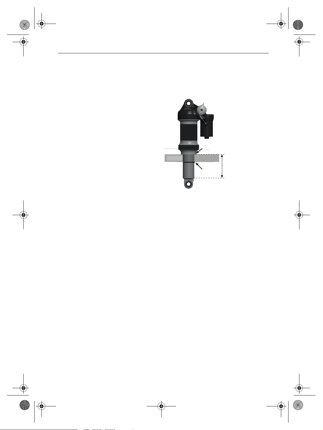
3.3.3.1 Rear frame damper structure
The rear frame damper features air suspension, a
compression damper and a rebound damper.
Figure 7: Example showing FOX rear frame damper
Description
034-03275_1.0_23.11.2018
1 Guide rod eye
2Air valve
3 Setting wheel
4 Lever
5 Air chamber
6O-ring
31

1
2
3
4
5
EN_034-03275_1.0_0.01_09.18_BULLS FAZUA_Inhalt.book Page 32 Friday, November 23, 2018 1:44 PM
Description
3.4 Brake system
The bicycle's brake system comprises either a
hydraulic:
• rim brake on the front and rear wheels,
• disc brake on the front and rear wheels or
• a rim brake on the front and rear wheels and an
additional back-pedal brake.
3.4.1 Rim brake
Alternative
Figure 8: Rim brake components with details; Magura HS22 used as an
example
1 Rear wheel rim brake
2 Brake booster
3 Brake lining
4 Handlebars with brake levers
5 Front wheel rim brake
The rim brake stops the wheel moving when the rider
pulls the brake lever, causing two brake linings,
positioned opposite one another, to be pressed onto
the rims.
32
034-03275_1.0_23.11.2018

21
EN_034-03275_1.0_0.01_09.18_BULLS FAZUA_Inhalt.book Page 33 Friday, November 23, 2018 1:44 PM
The hydraulic rim brake features a locking lever
Figure 9: Rim brake locking lever, closed (1) and open (2)
The rim brake locking lever is not marked with any
lettering. Only a specialist dealer may set the rim brake
locking lever.
Description
034-03275_1.0_23.11.2018
33

1
3
4
5
EN_034-03275_1.0_0.01_09.18_BULLS FAZUA_Inhalt.book Page 34 Friday, November 23, 2018 1:44 PM
Description
3.4.2 Disc brake
Alternative
Figure 10: Bicycle brake system with a disc brake, example
1Brake disc
2 Brake calliper with brake linings
3 Handlebars with brake levers
4 Front wheel brake disc
5 Rear wheel brake disc
2
On a bicycle with a disc brake, the brake disc is
screwed permanently to the hub of the wheel.
The brake lever is pulled to increase brake pressure.
The brake fluid is used to transfer pressure through
the brake lines to the cylinders in the brake calliper.
The braking force is boosted by a speed reduction and
applied to the brake linings. These apply the brake
disc mechanically. If the brake lever is pulled, the
brake linings are pressed against the brake disc, and
the movement of the wheel is decelerated until it
comes to a stop.
34
034-03275_1.0_23.11.2018

2
3
4
1
EN_034-03275_1.0_0.01_09.18_BULLS FAZUA_Inhalt.book Page 35 Friday, November 23, 2018 1:44 PM
3.4.3 Back-pedal brake
Alternative
Figure 11: Brake system with a back-pedal brake, example
1 Rear wheel rim brake
2 Handlebars with brake levers
3 Front wheel rim brake
4 Pedal
5 Back-pedal brake
Description
5
The back-pedal brake stops the movement of the rear
wheel when the rider pedals in the opposite direction
to the direction of travel.
034-03275_1.0_23.11.2018
35

2
3
4
1
EN_034-03275_1.0_0.01_09.18_BULLS FAZUA_Inhalt.book Page 36 Friday, November 23, 2018 1:44 PM
Description
3.5 Electric drive system
The bicycle is driven by muscle power via the chain
drive. The force which is applied by pedalling in the
direction of travel, drives the front chain wheel. The
chain transmits the force onto the rear chain wheel and
then onto the rear wheel.
Figure 12: Diagram of mechanical drive system
1 Direction of travel
2 Chain
3 Rear chain wheel
4 Front chain wheel
5 Pedal
The bicycle also has an integrated, electric drive
system.
36
5
034-03275_1.0_23.11.2018

1
234
EN_034-03275_1.0_0.01_09.18_BULLS FAZUA_Inhalt.book Page 37 Friday, November 23, 2018 1:44 PM
The electric drive system is made up of 5 components:
Figure 13: Diagram of electric drive system
1 Control panel
2 Bottom-bracket gears
3 Drive unit
4 Rechargeable battery
5 A charger which is designed for the battery.
Description
034-03275_1.0_23.11.2018
37

1
2
EN_034-03275_1.0_0.01_09.18_BULLS FAZUA_Inhalt.book Page 38 Friday, November 23, 2018 1:44 PM
Description
3.5.1 Drive unit
Figure 14: Drive unit
As soon as the required muscle power from the rider
pedalling passes a certain level, the motor is activated
gently and assists the pedalling motion of the rider.
The motor force is determined by the set level of
assistance. The system performance is determined
using the pedal assistance settings on the control
panel.
38
The bicycle does not have a separate emergency stop
or emergency shut-off button. The motor switches off
automatically as soon as the rider no longer pedals,
the temperature is outside the permitted range, there
is an overload or the shut-off speed of 25 km/h has
been reached.
When you step on the pedals again and the speed
drops below 25 km/h, the system starts again
A push assist system can be activated. The speed
depends on the selected gear. The rider brakes the
bicycle by holding the bicycle while pushing.
034-03275_1.0_23.11.2018

1
2
3
EN_034-03275_1.0_0.01_09.18_BULLS FAZUA_Inhalt.book Page 39 Friday, November 23, 2018 1:44 PM
3.5.2 Rechargeable battery
Figure 15: Rechargeable battery, view of charging port side
1 Charging port
2 On-Off button
3 Charge status indicator (battery)
Description
034-03275_1.0_23.11.2018
The lithium ion battery has an internal electronic
protection circuit. This is matched to the charger and
bicycle motor. The battery temperature is monitored at
all times. The battery is protected against deep
discharge, overcharging, overheating and short
circuit. In the event of a hazard, a protective circuit
switches the battery off automatically. If the bicycle
has not been moved for 10 hours and no button has
been pressed on the control panel or the charge status
of the battery falls below 30%, the bicycle has not
been moved for 3 hours and no button has been
pressed on the control panel, the electric drive system
and the battery automatically switch off to save
energy.
39

EN_034-03275_1.0_0.01_09.18_BULLS FAZUA_Inhalt.book Page 40 Friday, November 23, 2018 1:44 PM
Description
The battery's service life can be extended if it is well
maintained and, above all, stored at the correct
temperatures. The battery charge status will decrease
with age, even if the battery is maintained properly. If
the operating time is severely shortened after
charging, this is a sign that battery has reached the
end of its useful life.
Transportation temperature 5°C–25°C
Ideal transportation temperature 10 °C–15 °C
Storage temperature 5°C–25°C
Ideal storage temperature 10 °C–15 °C
Charging ambient temperature 10 °C–30 °C
Table 7: Rechargeable battery technical data
When the battery is switched on, the charge status
indicator shows the start animation. The LEDs then
briefly indicate the charge status of the battery.
40
If the battery is switched on, the charge status can be
queried by briefly pressing the On-Off button.
The five green LEDs on the charge status indicator
show the battery charge status when the battery is
switched on. Each LED represents 20% of the charge
status.
When the battery is discharged, the last LED lights up
intermittently. The charge status of the battery is also
shown on the display.
034-03275_1.0_23.11.2018

2
3
4
5
7
6
6
6
6
6
6
6
6
6
6
EN_034-03275_1.0_0.01_09.18_BULLS FAZUA_Inhalt.book Page 41 Friday, November 23, 2018 1:44 PM
3.5.3 Control panel
1
Figure 16: Overview of the structure and operating elements
Designation
1 Display bar
2 Top button
3 Middle button
4 Bottom button
5 Extension cable
6 Charge status indicator or pedal assistance
7 Status screen
Table 8: Operating element overview
Description
The control panel controls the drive system via three
buttons and displays either the charge status of the
battery or the pedal assistance selected.
The bicycle's battery supplies the control panel with
energy when a sufficiently charged battery is inserted
into the bicycle, and the drive system is switched on.
034-03275_1.0_23.11.2018
41

EN_034-03275_1.0_0.01_09.18_BULLS FAZUA_Inhalt.book Page 42 Friday, November 23, 2018 1:44 PM
Description
Operating temperature -20 ... +60 °C
Storage temperature -20 ... +60 °C
Protection rating
(with USB cover closed)
Weight about 0.075 kg
Table 9: Display technical data
3.5.3.1 Display bar
The control panel display bar consists of 11 LEDs.
The uppermost LED serves as a status display to
provide information on the status of your e-bike. The
remaining 10 LEDs serve as an indicator for the
charge status and pedal assistance.
Status screen
The status screen indicates a status change or an
existing fault. The status indicator does not light up if
no fault is detected.
The different colours of the status screen have the
following meaning:
Colour Meaning
The status screen briefly flashes green after the
green
Yellow
Red
Table 10: Meaning of status screen colours
drive pack has been successfully installed in the
bicycle. This gives you a visual signal that the
system can now be switched on.
The status screen briefly turns yellow when a "soft
fault" is detected. This means that there is a
temporary or non-critical disturbance, which in most
cases leads to a loss of performance. In the event
of a "soft fault", you can still ride your bicycle.
However, this is not recommended.
The status screen briefly turns red when a "hard
fault" is detected. In the event of a "hard fault", the
bicycle cannot be operated and must be serviced.
IP54
42
034-03275_1.0_23.11.2018

EN_034-03275_1.0_0.01_09.18_BULLS FAZUA_Inhalt.book Page 43 Friday, November 23, 2018 1:44 PM
3.5.3.2 Level of assistance
You can adjust the desired level of assistance using
the control panel. The pedal assistance can be
changed at any time.
The higher the level of assistance, the more the drive
system assists the rider when pedalling. The following
levels of assistance are available.
The following levels of assistance are possible:
Level of assistance Use
NONE
BREEZE
RIVER
ROCKET
Table 11: Overview of levels of assistance
Motor assistance is deactivated. The
bicycle can be used as a normal
bicycle.
Low but effective support for
maximum range.
Reliable assistance for most usage
situations.
Maximum assistance for very
demanding excursions.
Description
034-03275_1.0_23.11.2018
Level of
assistance
NONE WHITE 0% 0 W
BREEZE GREEN 75% 125 W
RI V E R B L U E 150% 250 W
RO C K E T PINK 240% 400 W
Colour
Max.
assistance
factor
Max. output
Remaining range
Precise information about the range of your system is
not possible before or during an excursion. Several
factors can influence the range of the bicycle, such as
level of assistance, speed, gear switching habits, tyre
type and pressure, route and weather conditions,
weight of rider and bicycle or the condition or age of
the battery.
43

2
3
1
4
5
1
EN_034-03275_1.0_0.01_09.18_BULLS FAZUA_Inhalt.book Page 44 Friday, November 23, 2018 1:44 PM
Description
3.6 Charger
The lithium ion battery has an internal electronic
protection circuit. It is matched to the charger. The
bicycle may therefore only be charged using the
charger provided.
Nominal input voltage 100 ... 240 V AC
Frequency 50 ... 60 Hz
Output voltage 42 V DC
Charging current 2 A
Operating temperature -20 ... +60 °C
Storage temperature -20 ... +60 °C
Protection class IP 54
Weight about 0.6 kg
Table 12: Charger technical data
Figure 17: Charger detail
1 Mains plug
2 LED display charger
3Mains plug
4 Connecting cable
5 Power jack
44
034-03275_1.0_23.11.2018

EN_034-03275_1.0_0.01_09.18_BULLS FAZUA_Inhalt.book Page 45 Friday, November 23, 2018 1:44 PM
Technical data
4 Technical data
Bicycle
Transportation temperature -20 ... +60 °C
Operating temperature -20 ... +60 °C
Storage temperature -20 ... +60 °C
Discharging temperature -20 ... +60 °C
Charging temperature 0 ... +45 °C
Power output/system 250 W (0.25 kW)
Shut-off speed 25 km/h
Weight of the ready-to-ride bicycle See type plate
Table 13: Bicycle technical data
Drive unit
Continuous power rating 250 W
Max. output 400 W
Torque on chain, max. 60 Nm
Nominal voltage 36 V
Operating temperature -20 ... +60 °C
Storage temperature -20 ... +60 °C
Protection class IP 54
Weight about 2kg
Table 14: Drive unit technical data
034-03275_1.0_23.11.2018
45

EN_034-03275_1.0_0.01_09.18_BULLS FAZUA_Inhalt.book Page 46 Friday, November 23, 2018 1:44 PM
Technical data
Rechargeable battery
Type Lithium ion battery
Nominal voltage 36 V
Nominal capacity 7Ah
Power 252 Wh
Operating temperature -20 ... +60 °C
Storage temperature -20 ... +60 °C
Discharging temperature -20 ... +60 °C
Charging temperature 0 ... +45 °C
Protection class IP 54
Weight, approx. 1.4 kg
Table 15: Rechargeable battery technical data
Control panel
Operating temperature -20 ... +60 °C
Storage temperature -20 ... +60 °C
Protection rating
(with USB cover closed)
Weight about 0.075 kg
Table 16: Display technical data
46
IP54
034-03275_1.0_23.11.2018

EN_034-03275_1.0_0.01_09.18_BULLS FAZUA_Inhalt.book Page 47 Friday, November 23, 2018 1:44 PM
Technical data
Bottom-bracket gears
Assistance torque, max. 60 Nm
Q factor, min. 135 (without crank
Operating temperature -20 ... +60 °C
Storage temperature -20 ... +60 °C
Protection class IP 54
Chainline 49, 52 mm
Weight about 1.3 kg
Table 17: Bottom-bracket gears technical data
Charger
Nominal input voltage 100 ... 240 V AC
Frequency 50 ... 60 Hz
Output voltage 42 V DC
Charging current 2 A
Operating temperature -20 ... +60 °C
Storage temperature -20 ... +60 °C
arm)
Protection class IP 54
Weight about 0.6 kg
Table 18: Charger technical data
034-03275_1.0_23.11.2018
47

EN_034-03275_1.0_0.01_09.18_BULLS FAZUA_Inhalt.book Page 48 Friday, November 23, 2018 1:44 PM
Technical data
Emissions
A-weighted emission sound pressure level < 70 dB(A)
Total vibration level for the hands and
arms
Highest effective value of weighted
acceleration for the entire body
Table 19: Emissions from the bicycle*
*The safety requirements as per Electromagnetic Compatibility
Directive 2014/30/EU have been met. The bicycle and the
charger can be used in residential areas without restriction.
Tightening torque
Axle nut tightening torque 35 Nm - 40 Nm
Handlebars clamping screw maximum
tightening torque*
Table 20: Tightening torque values*
*if there is no other data on the component
<2.5m/s²
<0.5m/s²
5Nm - 7Nm
48
034-03275_1.0_23.11.2018

CAUTION
!
CAUTION
!
CAUTION
!
NOTICE
EN_034-03275_1.0_0.01_09.18_BULLS FAZUA_Inhalt.book Page 49 Friday, November 23, 2018 1:44 PM
Transportation, storage and assembly
5 Transportation, storage and
assembly
5.1 Transportation
Crash caused by unintentional activation
There is a risk of injury if the drive system is activated
unintentionally.
Remove the battery before the bicycle is
transported.
Risk of fire and explosion due to high
temperatures
Excessively high temperatures will damage the
battery. Batteries may self-ignite and explode.
Never expose batteries to sustained direct sunlight.
Oil leak if no transport securing device
034-03275_1.0_23.11.2018
The brake securing device prevents the brakes from
being applied accidentally during transport. This could
cause irreparable damage to the brake system or an oil
leak, which will harm the environment.
Never pull the brake lever when the wheel has been
dismounted.
Always use the transport securing system when
transporting dismounted wheels.
If the bicycle is lying flat, oil and grease may leak from
the bicycle.
If the shipping box with a bicycle is lying flat or on one
end, it does not provide the frame and the wheels with
adequate protection from damage.
Only transport the bicycle in an upright position.
49

NOTICE
EN_034-03275_1.0_0.01_09.18_BULLS FAZUA_Inhalt.book Page 50 Friday, November 23, 2018 1:44 PM
Transportation, storage and assembly
Bicycle rack systems which secure the bicycle
standing on its head by the handlebars or frame,
generate inadmissible forces on the components
during transportation. This can cause the supporting
parts to break.
Never use bicycle rack systems which secure the
bicycle standing on its head by the handlebars or
frame.
Take into account the ready-to-use bicycle's weight
when transporting it.
Remove the display and the batteries before
transporting the bicycle.
Protect the electrical components and connections
on the bicycle from the elements with suitable
protective covers.
50
Remove accessories, for example drinking bottles,
before transportation of the bicycle.
When transporting by car, you must use a suitable
bicycle rack system.
The specialist dealer will advise you on how to select
a suitable rack system properly and how to use it
safely.
Transport the bicycle in a dry, clean place where it
is protected from direct sunlight.
When shipping the bicycle, we recommend that you
have the bicycle partially dismantled in the proper
manner and packaged by the specialist dealer.
034-03275_1.0_23.11.2018

EN_034-03275_1.0_0.01_09.18_BULLS FAZUA_Inhalt.book Page 51 Friday, November 23, 2018 1:44 PM
Transportation, storage and assembly
5.1.1 Transporting the battery
Batteries are subject to hazardous goods regulations.
Undamaged batteries may be transported by private
persons in road traffic. Commercial transport requires
compliance with regulations concerning packaging,
labelling and the transportation of hazardous goods.
Open contacts must be covered and the battery
securely packaged. The parcel service must be made
aware of the presence of hazardous goods in the
packaging.
5.1.2 Using the transport securing system
Insert the transport securing devices between the
brake linings.
The transport securing device is squeezed between
the two linings.
Figure 18: Fastening the transport securing device
Transportation temperature -20 ... +60 °C
Table 21: Bicycle transport temperature
034-03275_1.0_23.11.2018
51

CAUTION
!
NOTICE
NOTICE
EN_034-03275_1.0_0.01_09.18_BULLS FAZUA_Inhalt.book Page 52 Friday, November 23, 2018 1:44 PM
Transportation, storage and assembly
5.2 Storing
Risk of fire and explosion due to high
temperatures
Excessively high temperatures will damage batteries.
Batteries may self-ignite and explode.
Protect batteries against heat.
Never expose batteries to sustained direct sunlight.
If the bicycle is lying flat, oil and grease may leak from
the bicycle.
If the shipping box with a bicycle is lying flat or on one
end, it does not provide the frame and the wheels with
adequate protection from damage.
Only store the bicycle in an upright position.
The battery discharges when not in use. Storing a
discharged battery for longer periods can cause
serious damage to your battery or significantly reduce
its capacity.
I f the bicyc l e features a hydrauli c seat post, f ix only
the lower seat post or the frame into a fitting stand
to prevent damage to the upper seat post and the
seat post lever.
Never place a bicycle with a hydraulic seat post
upside down on the floor; otherwise you, will
damage the seat post lever.
Store the bicycle, battery and charger in a dry,
clean location.
Storage temperature -20 ... +60 °C
Table 22: Bicycle storage temperature
52
034-03275_1.0_23.11.2018
NOTICE
NOTICE
EN_034-03275_1.0_0.01_09.18_BULLS FAZUA_Inhalt.book Page 53 Friday, November 23, 2018 1:44 PM
Transportation, storage and assembly
5.2.1 Break in operation
The battery discharges when not in use. Storing a
discharged battery for longer periods can cause
serious damage to your battery or significantly reduce
its capacity.
The battery may become damaged if it is connected
permanently to the charger.
Never connect the battery to the charger
permanently.
If the bicycle is to be removed from service for longer
than four weeks, e.g. in winter, a break in operation
has to be prepared. It is recommended to store the
battery and the drive unit.
5.2.1.1 Preparing a break in operation
Remove the battery and drive unit from the bicycle.
Charge the battery to 60% (three LEDs of the charge
status indicator light up).
The bicycle has to be cleaned with a damp cloth and
preserved with wax spray. Never wax the friction
surfaces of the brake.
Before longer periods without use, it is
recommendable to have your specialist dealer carry
out servicing and basic cleaning and apply
preservative agent.
5.2.1.2 Taking out of operation
Check the battery after 6 months. With a charge
status of 20% or less, charge the battery to 60%
again.
1 month -20 to +60 °C
3 months -20 to +45 °C
1 year -20 to +25 °C
Table 23: Storage time with 60% charge
034-03275_1.0_23.11.2018
53
CAUTION
!
EN_034-03275_1.0_0.01_09.18_BULLS FAZUA_Inhalt.book Page 54 Friday, November 23, 2018 1:44 PM
Transportation, storage and assembly
5.3 Assembly
Crushing caused by unintentional activation
There is a risk of injury if the drive system is activated
unintentionally.
Remove the battery if it is not absolutely necessary
for assembly.
Assemble the bicycle in a clean and dry environment.
The working environment temperature should be
between 15 °C and 25 °C.
Working environment temperature 15 °C–25 °C
Table 24: Working environment temperature
If a fitting stand is used, it must be approved for a
maximum weight of 30 kg.
To reduce the weight, we recommend that you always
disconnect the battery from the bicycle when using the
fitting stand.
5.3.1 Required tools
The following tools are required to assemble the
bicycle:
•Knife
• Hexagon socket spanner 2 (2.5 mm, 3, mm 4 mm,
5 mm, 6 mm and 8 mm)
• Torque wrench with working range between 5 and
40 Nm
• Twelve-point square socket T-25
• Ring spanner (8 mm, 9 mm, 10 mm, 13 mm, 14 mm
and 15 mm) and
• Cross, flat head and ordinary screwdriver.
54
034-03275_1.0_23.11.2018

CAUTION
!
EN_034-03275_1.0_0.01_09.18_BULLS FAZUA_Inhalt.book Page 55 Friday, November 23, 2018 1:44 PM
Transportation, storage and assembly
5.3.2 Unpacking
Hand injuries caused by cardboard packaging
The shipping carton is closed with metal staples. There
is a risk of puncture wounds and cuts when unpacking
and crushing the packaging.
Wear suitable hand protection.
Remove the metal staples with pliers before the
shipping carton is opened.
The packaging material consists mainly of cardboard
and plastic film.
The packaging has to be disposed of in accordance
with the regulations of the authorities.
5.3.3 Scope of delivery
The bicycle was completely assembled in the factory
for test purposes and then dismantled for
transportation.
034-03275_1.0_23.11.2018
The bicycle is 95–98% pre-assembled. The scope of
delivery includes:
• the pre-assembled bicycle
• the front wheel
• the pedals
• quick release (optional)
• the charger
• the operating instructions.
The battery is supplied separately from the bicycle.
55

CAUTION
!
CAUTION
!
EN_034-03275_1.0_0.01_09.18_BULLS FAZUA_Inhalt.book Page 56 Friday, November 23, 2018 1:44 PM
Transportation, storage and assembly
5.3.4 Commissioning
Fire and explosion caused by incorrect charger
Batteries which are recharged with an unsuitable
charger may become damaged internally. This may
result in fire or an explosion.
Only ever use the battery with the supplied charger.
Mark the supplied charger and these operating
instructions clearly to prevent mix-ups – with the
bicycle frame number or type number, for example .
Burns from hot drive
The drive cooler can become extremely hot during use.
Contact may cause burns.
Leave the drive unit to cool before cleaning.
Since initial commissioning of the bicycle requires
special tools and specialist knowledge, only trained
specialist staff may perform initial commissioning.
56
Experience has shown that a bicycle which has not yet
been sold, is spontaneously handed to consumers as
soon as it appears ready to ride.
For this reason, every bicycle must be prepared, so
that it is fully ready for use immediately after being
assembled.
Staff should work through the initial commissioning
check list to prepare the bicycle, so that it is ready
to ride.
034-03275_1.0_23.11.2018

EN_034-03275_1.0_0.01_09.18_BULLS FAZUA_Inhalt.book Page 57 Friday, November 23, 2018 1:44 PM
Transportation, storage and assembly
Initial commissioning check list
Check battery.
The battery is partially charged when delivered. Fully charge the
battery to ensure full power.
Mount the wheels, quick release and pedals.
Re-adjust the quick release clamping force if necessary.
Thoroughly degrease the brake discs in disc brakes or the brake
sides and linings in rim brakes with brake cleaner or spirit.
Place handlebars, stem and saddle in the functional position
and check they are firmly in place.
Check all the components to make sure that they are firmly in
place. Check all the settings and the tightening torque on the
axle nuts.
Check the entire cable harness to make sure that it is routed
properly:
• You must prevent the cable harness from coming into
contact with moving parts.
• The cable routes must be smooth and free from sharp edges.
• Moving parts must not apply any pressure or tension to the
cable harness.
034-03275_1.0_23.11.2018
Check the drive system, the light equipment and the brakes to
make sure that they are fully functional and effective.
Adjust the headlight.
Set the drive system has to the national language and the
appropriate system of measurement.
Check the software version of the drive system and update it as
necessary.
Take a test drive to check the brake system, gear shift and the
electric drive system.
57

WARNING
!
EN_034-03275_1.0_0.01_09.18_BULLS FAZUA_Inhalt.book Page 58 Friday, November 23, 2018 1:44 PM
Transportation, storage and assembly
5.3.4.1 Checking the battery
Fire and explosion due to defective battery
The safety electronics on damaged or faulty batteries
may fail. The residual voltage can cause a short
circuit. The battery may self-ignite and explode.
Never charge a defective battery.
The battery must be checked before it is charged for
the first time.
Press the On-Off button (battery).
If none of the LEDs on the charge status indicator
light up, the battery may be damaged.
The battery can be charged if at least one, but not
all, of the LEDs on the charge status indicator is lit
up. Fully charge the battery before initial
commissioning in order to ensure that the full
capacity of the battery is available.
58
After initial commissioning and before every further
use, the battery is switched on using the On-Off
button.
034-03275_1.0_23.11.2018

EN_034-03275_1.0_0.01_09.18_BULLS FAZUA_Inhalt.book Page 59 Friday, November 23, 2018 1:44 PM
Transportation, storage and assembly
5.3.5 Mounting the wheel in the Suntour fork
Alternative
5.3.5.1 Mounting the wheel with screw-on axle (15 mm)
Alternative
Insert the axle completely on the drive side.
Figure 19: Fully inserting the axle
Tighten the axle with a 5 mm hexagon socket
spanner to 8–10 Nm.
Figure 20: Tightening the axle
034-03275_1.0_23.11.2018
59

EN_034-03275_1.0_0.01_09.18_BULLS FAZUA_Inhalt.book Page 60 Friday, November 23, 2018 1:44 PM
Transportation, storage and assembly
Insert the securing screw on the non-drive side.
Figure 21: Pushing the quick release lever into the axle
Tighten the securing screw with a 5 mm hexagon
socket spanner to 5–6 Nm.
The lever is mounted.
Figure 22: Tightening the securing screw
60
034-03275_1.0_23.11.2018

EN_034-03275_1.0_0.01_09.18_BULLS FAZUA_Inhalt.book Page 61 Friday, November 23, 2018 1:44 PM
Transportation, storage and assembly
5.3.5.2 Mounting the wheel with screw-on axle (20 mm)
Alternative
Insert the axle completely on the drive side.
Figure 23: Tightening the inserted axle
Tighten the securing clip with a 4 mm hexagon
socket spanner to 7 Nm.
Figure 24: Tightening the axle
034-03275_1.0_23.11.2018
61

CAUTION
!
CAUTION
!
CAUTION
!
EN_034-03275_1.0_0.01_09.18_BULLS FAZUA_Inhalt.book Page 62 Friday, November 23, 2018 1:44 PM
Transportation, storage and assembly
5.3.5.3 Mounting the wheel with a quick release axle
Alternative
Crash caused by loose quick release axle
A faulty or incorrectly installed quick release axle may
become caught in the brake disc and block the wheel.
This will cause a crash.
Never fit a defective quick release axle.
Crash caused by faulty or incorrectly installed
quick release axle
The brake disc becomes very hot during operation.
Parts of the quick release axle may become damaged
as a result. The quick release axle becomes loose.
This will result in a crash and injuries.
The quick release axle and the brake disc must be
opposite one another.
Crash caused by incorrectly set quick release axle
62
Insufficient clamping force will cause a detrimental
transmission of force. The suspension fork or the quick
release axle may break. This will result in a crash and
injuries.
Never fasten a quick release axle with a tool, such
as a hammer or pliers.
034-03275_1.0_23.11.2018

EN_034-03275_1.0_0.01_09.18_BULLS FAZUA_Inhalt.book Page 63 Friday, November 23, 2018 1:44 PM
Transportation, storage and assembly
Insert the axle into the hub on the drive side.
Clamping version II.
Figure 25: Pushing the axle into the hub
Tighten the axle with the red handle.
Figure 26: Tightening the axle
034-03275_1.0_23.11.2018
63

EN_034-03275_1.0_0.01_09.18_BULLS FAZUA_Inhalt.book Page 64 Friday, November 23, 2018 1:44 PM
Transportation, storage and assembly
Push the quick release lever into the axle.
Figure 27: Pushing the quick release lever into the axle
Reverse the quick release lever.
The lever is secured.
Figure 28: Securing the lever
64
034-03275_1.0_23.11.2018

EN_034-03275_1.0_0.01_09.18_BULLS FAZUA_Inhalt.book Page 65 Friday, November 23, 2018 1:44 PM
Transportation, storage and assembly
Check the position and clamping force of the quick
release lever. The quick release lever must be flush
with the lower housing. You must be able to see a
slight impression on the palm of your hand when
you close the quick release lever.
Figure 29: Perfect position for the clamping lever
Use a 4 mm hexagon socket spanner to adjust the
clamping lever clamping force if required.
Afterwards, check the quick release lever position
and clamping force.
Figure 30: Adjusting the quick release clamping force
034-03275_1.0_23.11.2018
65

CAUTION
!
CAUTION
!
CAUTION
!
EN_034-03275_1.0_0.01_09.18_BULLS FAZUA_Inhalt.book Page 66 Friday, November 23, 2018 1:44 PM
Transportation, storage and assembly
5.3.6 Mounting the wheel with a quick release
Alternative
Crash caused by unfastened quick release
A faulty or incorrectly installed quick release may
become caught in the brake disc and block the wheel.
This will cause a crash.
Never fit a defective quick release.
Crash caused by faulty or incorrectly installed
quick release
The brake disc becomes very hot during operation.
Parts of the quick release may become damaged as a
result. The quick release comes loose. This will result
in a crash and injuries.
The front wheel quick release lever and the brake
disc must be situated on opposite sides.
Crash caused by incorrectly set clamping force
66
Excessively high clamping force will damage the quick
release and cause it to lose its function.
Insufficient clamping force will cause a detrimental
transmission of force. The suspension fork or the quick
release may break. This will result in a crash and
injuries.
Never fasten a quick release using a tool (e.g.
hammer or pliers).
Only use the clamping lever with the specified set
clamping force.
034-03275_1.0_23.11.2018

EN_034-03275_1.0_0.01_09.18_BULLS FAZUA_Inhalt.book Page 67 Friday, November 23, 2018 1:44 PM
Transportation, storage and assembly
Before mounting, ensure that the quick release
flange is extended. Open the lever completely.
Figure 31: Open and closed flange
Push in the quick release until you hear a clicking
sound. Make sure that the flange is extended.
Figure 32: Pushing the quick release in
034-03275_1.0_23.11.2018
67

EN_034-03275_1.0_0.01_09.18_BULLS FAZUA_Inhalt.book Page 68 Friday, November 23, 2018 1:44 PM
Transportation, storage and assembly
Adjust the clamping with a half-open clamping lever
until the flange reaches the fork end.
Figure 33: Adjusting the clamping
Fully close the quick release. Check the quick
release to ensure it is firmly in place and adjust on
the flange if necessary.
The lever is secured.
Figure 34: Closing the quick release
68
034-03275_1.0_23.11.2018

EN_034-03275_1.0_0.01_09.18_BULLS FAZUA_Inhalt.book Page 69 Friday, November 23, 2018 1:44 PM
Transportation, storage and assembly
5.3.7 Mounting the wheel in the FOX fork
Alternative
5.3.7.1 Mounting the wheel with the quick release (15 mm)
Alternative
The procedure for installing the 15 x 100 mm and
15 x 110 mm quick releases is the same.
Place the front wheel in the fork ends of the fork.
Push the axle through the fork end on the non-drive
side and hub.
Figure 35: Pushing the quick release in
Open the axle lever.
Turn the axle five to six complete revolutions
clockwise into the axle nut.
Close the quick release. The lever must be
tensioned to the point that it leaves a mark on your
hand.
034-03275_1.0_23.11.2018
69

1-20 mm
1
2
3
4
5
EN_034-03275_1.0_0.01_09.18_BULLS FAZUA_Inhalt.book Page 70 Friday, November 23, 2018 1:44 PM
Transportation, storage and assembly
The lever must be 1 to 20 mm ahead of the fork leg
in the closed position.
Figure 36: Spacing between lever and fork leg
If the lever is tensioned too little or too much when
closed in the recommended position (1 to 20 mm
ahead of the fork), the quick release must be
adjusted.
5.3.7.2 Adjusting the FOX quick release
Figure 37: Structure of quick release from rear with (1) axle nut lock, (2) axle
nut securing screw, (3) directional arrow, (4) axle setting value
and (5) axle nut
70
034-03275_1.0_23.11.2018

EN_034-03275_1.0_0.01_09.18_BULLS FAZUA_Inhalt.book Page 71 Friday, November 23, 2018 1:44 PM
Transportation, storage and assembly
Record the axle setting value (4) indicated by the
directional arrow (3).
Loosen the axle nut securing screw (2) with a
2.5 mm hex key by approx. four revolutions, but do
not remove the screw completely.
Turn the quick release lever to the open position
and loosen the axle by approx. four revolutions.
Press the axle inward from the side of the open
lever. This pushes out the axle nut securing screw
so that you can turn it out of the way.
Push the axle further forward and turn the axle nut
clockwise to increase the lever tension or anticlockwise to reduce the lever tension.
Reinsert the axle nut lock and tighten the screw to
0.9 Nm (8 in-lb).
034-03275_1.0_23.11.2018
Repeat the steps for installing the axle to check
proper installation and correct adjustment.
71

EN_034-03275_1.0_0.01_09.18_BULLS FAZUA_Inhalt.book Page 72 Friday, November 23, 2018 1:44 PM
Transportation, storage and assembly
5.3.7.3 Mounting the wheel with Kabolt axles
Alternative
The procedure for installing the 15 x 100 mm and
15 x 110 mm Kabolt axles is the same.
Place the front wheel in the fork ends of the fork.
Push the Kabolt axle through the fork end on the
non-drive side and hub.
Figure 38: Pushing the Kabolt axle in
Tighten the Kabolt axle screw to 17 Nm (150 in-lb)
with a 6 mm hex key.
72
034-03275_1.0_23.11.2018

EN_034-03275_1.0_0.01_09.18_BULLS FAZUA_Inhalt.book Page 73 Friday, November 23, 2018 1:44 PM
Transportation, storage and assembly
5.3.7.4 Checking the stem and handlebars
Checking connections
Stand in front of the bicycle to check whether the
handlebars, stem and fork shaft are firmly attached
to one another. Clamp the front wheel between
your legs. Grasp the handlebar grips. Try to twist
the handlebars towards the front wheel.
The stem must not move or twist.
Firm hold
Place your entire body weight on the handlebars
with the quick release lever closed to check that the
stem is firmly in place.
The handlebars shaft must not move downwards in
the fork shaft.
034-03275_1.0_23.11.2018
If the handlebars shaft should move in the fork
shaft, increase the quick release lever tensioning.
To do so, turn the knurled nut slightly in a clockwise
direction with the quick release lever open.
Close the lever and check the stem is firmly in
position.
73

EN_034-03275_1.0_0.01_09.18_BULLS FAZUA_Inhalt.book Page 74 Friday, November 23, 2018 1:44 PM
Transportation, storage and assembly
Checking the headset backlash
To check the handlebar headset backlash, close
the quick release lever on the stem. Place the
fingers of one hand on the upper headset cup, pull
the front wheel brake with the other hand and try to
push the bicycle backwards and forwards.
The headset cup halves must not move towards
one another while you are doing this. Note that
there may be noticeable backlash due to worn-out
bearing bushes or brake lining backlash in
suspension forks and disc brakes.
If there is headset backlash in the steering headset,
you must adjust it as soon as possible; otherwise,
the headset will become damaged. You must make
the adjustment as described in the stem manual.
5.3.8 Sale of the bicycle
74
Fill out the data sheet on the first page of the
operating instructions.
Adjust the bicycle to the rider.
Set the stand and the shifter, and show the
purchaser the settings.
Instruct the operator or rider how to use all the
functions of the bicycle.
034-03275_1.0_23.11.2018

CAUTION
!
EN_034-03275_1.0_0.01_09.18_BULLS FAZUA_Inhalt.book Page 75 Friday, November 23, 2018 1:44 PM
Before the first ride
6 Before the first ride
Crash caused by incorrectly adjusted torques
If a screw is fastened too tightly, it may break. If a
screw is not fastened enough, it may loosen. This will
result in a crash and injuries.
Always observe the indicated torques on the screw
or in the operating instructions.
Only a correctly adjusted bicycle will guarantee you
the desired ride comfort and health-promoting activity.
Therefore adjust the saddle, the handlebars and the
suspension to your body and your preferred riding style
before the first ride.
6.1 Adjusting the saddle
6.1.1 Adjusting the saddle tilt
The saddle tilt must be adjusted to the seat height, the
saddle and handlebar position, and the saddle shape
to ensure an optimum fit. The seating position can be
optimised in this way if needed. First, readjust the
saddle after finding the handlebar position you prefer.
034-03275_1.0_23.11.2018
75

EN_034-03275_1.0_0.01_09.18_BULLS FAZUA_Inhalt.book Page 76 Friday, November 23, 2018 1:44 PM
Before the first ride
Place the saddle tilt in the horizontal position to
adjust the bicycle to your needs for the first time.
Figure 39: Horizontal saddle tilt
6.1.2 Determining the seat height
To determine the seat height safely, either push the
bicycle near to a wall, so that you can lean on the wall
to support yourself or ask another person to hold the
bicycle for you.
76
Climb onto the bicycle.
Place your heel on the pedal and extend your leg,
so that the pedal is at the lowest crank rotation
point.
The rider sits straight on the saddle if the seat is at
an optimum height. If this is not the case, you can
adjust the length of the seat post to your needs.
034-03275_1.0_23.11.2018

3
4
5
1
2
3
EN_034-03275_1.0_0.01_09.18_BULLS FAZUA_Inhalt.book Page 77 Friday, November 23, 2018 1:44 PM
Before the first ride
Figure 40: Optimal saddle height
6.1.3 Adjusting the seat height with quick release
Open the quick release on the seat post to change
the seat height. To do so, pull the clamping lever
away from the seat post.
Figure 41: Seat post quick release (3) with clamping lever (5) and setting
bolt (4) in the open position (1) and in the direction of the closed
position (2)
034-03275_1.0_23.11.2018
77

CAUTION
!
3
4
2
1
EN_034-03275_1.0_0.01_09.18_BULLS FAZUA_Inhalt.book Page 78 Friday, November 23, 2018 1:44 PM
Before the first ride
Set the seat post at the required height.
Crash caused by an excessively high seat post
setting
A seat post with is set too high will cause the seat post
or the frame to break. This will result in a crash and
injuries.
Do not pull the seat post out of the frame beyond
the minimum insertion depth marking.
Figure 42: Detailed view of the seat post – examples of the minimum insertion
depth marking
To close it, push the seat post clamping lever as far
as it will go into the seat post.
Check the clamping force of the quick releases.
78
034-03275_1.0_23.11.2018

.
ert wer
e Position zur Best
ber in einem späteren
chmals montieren.
ie den mitgelieferten Winkel mit der in
rrichtung und stecken Sie die Hülle in die
Remotehebel
5
Oder
28
12
EN_034-03275_1.0_0.01_09.18_BULLS FAZUA_Inhalt.book Page 79 Friday, November 23, 2018 1:44 PM
Before the first ride
6.1.4 Setting the height-adjustable seat post
When using your seat post for the first time, you
must give it a firm push downwards to set it in
motion. This is due to the natural tendency of the
seal to repel oil from the seal surface. You only
need to do this before the first use or after a longer
period of non-use. Once you have displaced the
post through its deflection, the oil spreads on the
seal and the post begins to function normally.
Figure 43: The seat post activation lever can be mounted either on the left (1)
or the right (2) side of the handlebars
6.1.4.1 Lowering the saddle
6.1.4.2 Raising the saddle
034-03275_1.0_23.11.2018
To lower the saddle, press your hand down on the
saddle or sit on the saddle.
Press the seat post activation lever and hold it
down.
Release the lever once you have reached the
required height.
Pull the seat post activation level.
Remove any pressure on the saddle and release
the lever once you have reached the required
height.
79

90°
EN_034-03275_1.0_0.01_09.18_BULLS FAZUA_Inhalt.book Page 80 Friday, November 23, 2018 1:44 PM
Before the first ride
6.1.5 Adjusting the seat position
The saddle can be shifted on the saddle frame. The
right horizontal position ensures an optimal leverage
position for legs. This prevents knee pain and painful
incorrect pelvis positions. If you have displaced the
saddle more than 10 mm, you then need to adjust the
saddle height again since both settings affect one
another.
To adjust the seat position safely, either push the
bicycle near to a wall, so that you can lean on the wall
to support yourself or ask another person to hold the
bicycle for you.
Climb onto the bicycle.
Place the pedals into the vertical position (3 o'clock
position) with your feet.
The rider is sitting in the optimal sitting position if
the knee cap perpendicular line runs through the
pedal axle. If the perpendicular line crosses behind
the pedal, bring the saddle forward. If the
perpendicular line crosses in front of the pedal,
bring the saddle back. Move the saddle within its
permitted displacement range only (marked on the
saddle stay).
Figure 44: Knee cap perpendicular line
80
034-03275_1.0_23.11.2018

CAUTION
!
EN_034-03275_1.0_0.01_09.18_BULLS FAZUA_Inhalt.book Page 81 Friday, November 23, 2018 1:44 PM
Before the first ride
6.2 Adjusting the handlebars
The handlebars must only be adjusted while the
bicycle is stationary.
Unfasten and adjust the designated screw
connections, and clamp them with the maximum
tightening torque for the clamping screws of the
handlebars.
Maximum tightening torque for the
clamping screws of the handlebars*
*if there is no other data on the component
Table 25: Handlebars clamping screw maximum tightening torque
Adjusting the stem
Crash caused by loose stem
Incorrectly fastened screws may come loose due to
impact. The stem may no longer be firmly fixed in its
position as a result. This will result in a crash and
injuries.
5Nm - 7Nm
034-03275_1.0_23.11.2018
Check the handlebars and the quick release system
are firmly in position after the first two hours of
riding.
81

CAUTION
!
1
2
EN_034-03275_1.0_0.01_09.18_BULLS FAZUA_Inhalt.book Page 82 Friday, November 23, 2018 1:44 PM
Before the first ride
6.2.1 Adjusting the height of the handlebars
Crash caused by incorrectly set clamping force
Excessively high clamping force will damage the quick
release and cause it to lose its function. Insufficient
clamping force will cause a detrimental transmission of
force. This can cause components to break. This will
result in a crash and injuries.
Never fasten a quick release using a tool (e.g.
hammer or pliers).
Only use the clamping lever with the specified set
clamping force.
Open the clamping lever.
Pull the locking lever on the stem up, and
simultaneously pivot the handlebars into the
desired position.
You feel the locking lever click into place.
Pull out the handlebars to the required height.
Lock the quick release.
Figure 45: Open (2) and closed (1) clamping lever on the stem; by.schulz
speedlifter used as an example
82
034-03275_1.0_23.11.2018

CAUTION
!
EN_034-03275_1.0_0.01_09.18_BULLS FAZUA_Inhalt.book Page 83 Friday, November 23, 2018 1:44 PM
Before the first ride
6.2.2 Turning the handlebars to the side
Alternative
Crash caused by incorrectly set clamping force
Excessively high clamping force will damage the quick
release and cause it to lose its function.
Insufficient clamping force will cause a detrimental
transmission of force. This will result in a crash and
injuries.
Never fasten a quick release using a tool (e.g.
hammer or pliers).
Only use the clamping lever with the specified set
clamping force.
Open the clamping lever.
Pull the locking lever on the stem up, and
simultaneously pivot the handlebars into the
desired position.
You feel the locking lever click into place.
Pull out the handlebars to the required height.
Lock the quick release.
Figure 46: Pulling locking lever upwards; by.schulz speedlifter used as an
example
034-03275_1.0_23.11.2018
83

EN_034-03275_1.0_0.01_09.18_BULLS FAZUA_Inhalt.book Page 84 Friday, November 23, 2018 1:44 PM
Before the first ride
6.2.2.1 Checking the clamping force of the quick releases
Open and close the quick releases on the stem or
the seat post.
The clamping force is sufficient if the clamping
lever can be moved easily from the open final
position into the middle and has to be pressed with
the fingers or base of the thumb from the middle
point onwards.
6.2.2.2 Adjusting the quick release clamping force
If the clamping lever on the handlebars cannot be
moved into its final position, screw out the knurled
nut.
Tighten the knurled nut on the seat post if the
clamping lever's clamping force is not sufficient.
If you are unable to set the clamping force, the
specialist dealer will need to check the quick release.
84
034-03275_1.0_23.11.2018

WARNING
!
1
EN_034-03275_1.0_0.01_09.18_BULLS FAZUA_Inhalt.book Page 85 Friday, November 23, 2018 1:44 PM
Before the first ride
6.3 Adjusting the brake lever
6.3.1 Adjusting the pressure point on a Magura brake
lever
Brake failure due to incorrect setting
If the pressure point is set with brakes where the brake
lining and brake disc have reached their wear limit, the
brakes may fail and cause an accident with injury.
Before you set the pressure point, ensure that the
brake lining and brake disc have not reached their
wear limit.
The pressure point setting is adjusted using the twist
knob.
Turn the twist knob towards the plus (+) symbol.
The brake lever moves closer to the handlebar grip.
Re-adjust the grip distance as necessary.
The lever pressure point activates sooner.
Figure 47: Using the twist knob (1) to adjust the pressure point
034-03275_1.0_23.11.2018
85

WARNING
!
EN_034-03275_1.0_0.01_09.18_BULLS FAZUA_Inhalt.book Page 86 Friday, November 23, 2018 1:44 PM
Before the first ride
6.3.2 Adjusting the grip distance
Crash caused by incorrectly set grip distance
If brake cylinders are set incorrectly or installed
wrongly, the braking power may be lost at any time.
This may cause you to fall from the bicycle and injure
yourself.
Once the grip distance has been set, check the
position of the brake cylinder and adjust it as
necessary.
Never correct the brake cylinder position without
special tools. Have a specialist dealer correct it.
The brake lever grip distance can be adjusted to
ensure that it can be reached more easily. Contact
your specialist dealer if the brake handle is too far from
the handlebars or is hard to use.
Figure 48: Brake lever grip distance
86
034-03275_1.0_23.11.2018

2
EN_034-03275_1.0_0.01_09.18_BULLS FAZUA_Inhalt.book Page 87 Friday, November 23, 2018 1:44 PM
Before the first ride
6.3.2.1 Adjusting the grip distance on a Magura brake lever
Alternative
Use a T25 TORX® wrench to turn the setting screw to
adjust the grip distance.
Turn the setting screw in the minus (‒) direction.
The brake lever moves closer to the handlebar grip.
Turn the setting screw in the plus (+) direction.
The brake lever moves away from the handlebar
grip.
1
Figure 49: Using the setting screw (2) to adjust the distance from the brake
lever to the handlebar grip (1)
034-03275_1.0_23.11.2018
87

CAUTION
!
NOTICE
EN_034-03275_1.0_0.01_09.18_BULLS FAZUA_Inhalt.book Page 88 Friday, November 23, 2018 1:44 PM
Before the first ride
6.4 Adjusting the suspension of the Suntour
fork
Alternative
The following Suntour forks can be installed in this
series of models:
Aion-35 Boost
NCX
NEX
XCM-ATB
XCM
XCR32
XCR34
Table 26: Overview of Suntour forks
Crash caused by incorrectly set suspension
If the suspension is adjusted incorrectly, the fork may
become damaged, so that problems may occur when
steering. This will result in a crash and injuries.
Never ride the bicycle without air in the air
suspension fork.
Never use the bicycle without adjusting the
suspension fork to the rider's weight.
Settings on the chassis change riding performance
significantly. You need to get used to the bicycle and
break it in to prevent accidents.
Air suspension fork
Air suspension fork
Steel suspension fork
Steel suspension fork
Steel suspension fork
Air suspension fork
Air suspension fork
88
The adjustment shown here represents a basic
setting. The rider should change the basic setting to
suit the surface and his/her preferences.
It is advisable to make a note of the basic setting.
This way, it can be used as the starting point for
subsequent, optimised settings and to safeguard
against unintentional changes.
034-03275_1.0_23.11.2018

EN_034-03275_1.0_0.01_09.18_BULLS FAZUA_Inhalt.book Page 89 Friday, November 23, 2018 1:44 PM
Before the first ride
6.4.1 Adjusting the negative deflection
Negative deflection (SAG) is compression of the fork
caused by the weight of the rider and their gear (e.g. a
backpack), the sitting position and the frame
geometry. This "SAG" is not caused by riding.
Each rider has a different weight and sitting position.
"SAG" depends on the rider's position and weight and
should be between 15% and 30% of the maximum fork
deflection, depending on bicycle usage and
preferences.
6.4.1.1 Adjusting the air suspension fork negative deflection
Alternative
The air valve is located under a cover on the head
of the left shock absorber. Screw off the cover.
Figure 50: Screw caps in different designs
Screw a high-pressure pump onto the valve.
Pump the suspension fork up to the desired
pressure. Never exceed the recommended
maximum air pressure. Comply with the values of
the filling pressure table.
Remove the high-pressure pump.
034-03275_1.0_23.11.2018
89

EN_034-03275_1.0_0.01_09.18_BULLS FAZUA_Inhalt.book Page 90 Friday, November 23, 2018 1:44 PM
Before the first ride
Rider weight AION, NEX XCR 32, XCR 34
< 55 kg 35 - 50 psi 40 - 55 psi
55 - 65 kg 50 - 60 psi 55 - 65 psi
65 - 75 g 60 - 70 psi 65 - 75 psi
75 - 85 kg 70 - 85 psi 75 - 85 psi
85 - 95 kg 85 - 100 psi 85 - 95 psi
< 100 kg + 105 psi + 100 psi
Max. pressure 150 psi 180 psi
Table 27: Filling pressure pump of the Suntour air forks
Measure the distance between the crown and the
dust wiper of the fork. This distance is the total
deflection of the fork.
Push a temporarily attached cable tie downward
against the dust wiper of the fork.
Put on your usual bicycling clothing, including
luggage.
Sit on the bicycle in your usual riding position and
support yourself (e.g. against a wall or tree).
Get off the bicycle without allowing it to deflect.
90
Measure the distance between the dust wiper and
the cable tie. This dimension is the "SAG." The
"SAG" value should be between 15% (hard) and
30% (soft) of the total fork deflection.
Increase or reduce the air pressure until you have
reached the desired "SAG."
Once the "SAG" is correct, re-tighten the blue air
cover cap clockwise.
034-03275_1.0_23.11.2018

EN_034-03275_1.0_0.01_09.18_BULLS FAZUA_Inhalt.book Page 91 Friday, November 23, 2018 1:44 PM
Before the first ride
If you cannot achieve the desired "SAG", you may
need to make an internal adjustment. For this purpose,
contact your specialist dealer.
6.4.1.2 Adjusting the steel suspension fork negative
deflection
Alternative
You can adjust the fork by tensioning the spring to the
rider's weight and their preferred riding style. It is not
the coil spring hardness which is adjusted; it is its pretensioning. This reduces the fork's negative deflection
when the rider sits on the bicycle.
Figure 51: Negative deflection setting wheel on the suspension fork crown
The setting wheel may be located under a plastic
cover on the suspension fork crown. Remove the
plastic cover by pulling it off upwards.
Turn the negative deflection setting wheel in a
clockwise direction to increase the spring pretensioning. Turn the negative deflection setting
wheel in an anti-clockwise direction to reduce it.
The ideal setting in relation to the weight of the rider
has been achieved when the shock absorber
deflects 3 mm under the stationary load of the rider.
Reattach the cover after the adjustment.
034-03275_1.0_23.11.2018
91

1
2
EN_034-03275_1.0_0.01_09.18_BULLS FAZUA_Inhalt.book Page 92 Friday, November 23, 2018 1:44 PM
Before the first ride
6.4.2 Adjusting the rebound
Alternative
The rebound defines the speed at which the fork
rebounds after being loaded. The rebound setting
depends on the air pressure setting. Higher "SAG"
settings require lower rebound settings.
Turn the rebound adjuster clockwise to the closed
position until it stops.
Figure 52: Suntour rebound adjuster (2) on the fork (1)
Turn the rebound adjuster anti-clockwise.
Adjust the rebound in such a way that the fork
rebounds quickly, but without bottoming out upward
during testing. Bottoming out is where the fork
rebounds too quickly and stops moving abruptly
once it has reached the full rebound distance. You
will hear and feel a slight knock when this occurs.
92
034-03275_1.0_23.11.2018

CAUTION
!
NOTICE
EN_034-03275_1.0_0.01_09.18_BULLS FAZUA_Inhalt.book Page 93 Friday, November 23, 2018 1:44 PM
Before the first ride
6.5 Adjusting the suspension of the FOX fork
Alternative
Crash caused by incorrectly set suspension
If the suspension is adjusted incorrectly, the fork may
become damaged, so that problems may occur when
steering. This will result in a crash and injuries.
Never ride the bicycle without air in the air
suspension fork.
Never use the bicycle without adjusting the
suspension fork to the rider's weight.
Settings on the chassis change riding performance
significantly. You need to get used to the bicycle and
break it in to prevent accidents.
The adjustment shown here represents a basic
setting. The rider should change the basic setting to
suit the surface and his/her preferences.
It is advisable to make a note of the basic setting.
This way, it can be used as the starting point for
subsequent, optimised settings and to safeguard
against unintentional changes.
6.5.1 Adjusting the negative deflection
Negative deflection (SAG) is compression of the fork
caused by the weight of the rider and their gear (e.g. a
backpack), the sitting position and the frame
geometry. This "SAG" is not caused by riding. Each
rider has a different weight and sitting position. "SAG"
depends on the rider's position and weight and should
be between 15% and 20% of the maximum fork
deflection, depending on bicycle usage and
preferences.
034-03275_1.0_23.11.2018
93

EN_034-03275_1.0_0.01_09.18_BULLS FAZUA_Inhalt.book Page 94 Friday, November 23, 2018 1:44 PM
Before the first ride
When adjusting the "SAG", ensure that each
compression adjuster is in the open position, i.e.
turned clockwise until it stops.
The pressure is to be measured at an ambient
temperature of 21 to 24 °C.
The air valve is located under a blue cover on the
head of the left shock absorber. S c rew of f t h e cov e r
anti-clockwise.
Place a high-pressure pump on the valve.
Pump the suspension fork up to the desired
pressure. Never exceed the recommended
maximum air pressure. Comply with the values of
the filling pressure table.
Remove the high-pressure pump.
Rider weight Rhythm 34 Rhythm 36
Minimum air pressure 40 psi (2.8 bar) 40 psi (2.8 bar)
54 - 59 kg 58 psi 55 psi
59 - 64 kg 63 psi 59 psi
64 - 68 kg 68 psi 63 psi
68 - 73 kg 72 psi 67 psi
73 - 77 kg 77 psi 72 psi
77 - 82 kg 82 psi 76 psi
82 - 86 kg 86 psi 80 psi
86 - 91 kg 91 psi 85 psi
91 - 95 kg 96 psi 89 psi
95 - 100 kg 100 psi 93 psi
100 - 104 kg 105 psi 97 psi
104 - 109 kg 110 psi 102 psi
109 - 113 kg 114 psi 106 psi
Max. pressure 120 psi (8.3 bar) 120 psi (8.3 bar)
Table 28: Filling pressure table of the FOX air fork
94
034-03275_1.0_23.11.2018

EN_034-03275_1.0_0.01_09.18_BULLS FAZUA_Inhalt.book Page 95 Friday, November 23, 2018 1:44 PM
Before the first ride
Measure the distance between the crown and the
dust wiper of the fork. This distance is the "total
deflection of the fork."
Push the O-ring downward against the dust wiper of
the fork. If an O-ring is not available, attach a cable
tie to the stanchion temporarily.
Put on your usual bicycling clothing, including
luggage.
Sit on the bicycle in your usual riding position and
support yourself (e.g. against a wall or tree).
Get off the bicycle without allowing it to deflect.
Measure the distance between the dust wiper and
the O-ring or cable tie. This dimension is the "SAG."
The recommended "SAG" value is between 15%
(hard) and 20% (soft) of the "total fork deflection."
034-03275_1.0_23.11.2018
Increase or reduce the air pressure until you have
reached the desired "SAG."
Once the "SAG" is correct, re-tighten the blue air
cover cap clockwise.
If you cannot achieve the desired "SAG", you may
need to make an internal adjustment. For this purpose,
contact your specialist dealer.
95

1
EN_034-03275_1.0_0.01_09.18_BULLS FAZUA_Inhalt.book Page 96 Friday, November 23, 2018 1:44 PM
Before the first ride
6.5.2 Adjusting the rebound
The rebound defines the speed at which the fork
rebounds after being loaded. The rebound setting
depends on the air pressure setting. Higher "SAG"
settings require lower rebound settings.
Turn the rebound adjuster clockwise to the closed
position until it stops.
Figure 53: FOX rebound adjuster (1) on the fork
Turn the rebound adjuster anti-clockwise.
Adjust the rebound in such a way that the fork
rebounds quickly, but without bottoming out upward
during testing. Bottoming out is where the fork
rebounds too quickly and stops moving abruptly
once it has reached the full rebound distance. You
will hear and feel a slight knock when this occurs.
96
034-03275_1.0_23.11.2018

NOTICE
EN_034-03275_1.0_0.01_09.18_BULLS FAZUA_Inhalt.book Page 97 Friday, November 23, 2018 1:44 PM
Before the first ride
6.6 Adjusting the Suntour rear frame damper
Alternative
6.6.1 Adjusting the negative deflection
If the air pressure in the rear frame damper is
exceeded or undershot, the damper can be
permanently damaged.
Do not exceed the maximum air pressure of 300 psi
(20 bar).
Negative deflection (SAG) is compression of the rear
frame damper caused by the weight of the rider and
their gear (e.g. a backpack), the sitting position and
the frame geometry. This "SAG" is not caused by
riding. Each rider has a different weight and sitting
position. "SAG" depends on the rider's position and
weight and should be between 25% and 30% of the
maximum rear frame damper deflection, depending on
bicycle usage and preferences.
034-03275_1.0_23.11.2018
Set the compression adjuster to the OPEN position
so that the SAG setting is not affected.
Remove the cap on the air valve.
Attach a high-pressure damper pump to the valve.
Adjust the air pressure of the damper so that it
corresponds to your weight.
Remove the high-pressure pump.
Measure the distance between the rubber air
chamber seal and the end of the damper. This
distance is the "total damper deflection".
Put on your usual bicycling clothing, including
luggage. Sit on the bicycle in your usual riding
position and support yourself, e.g. against a wall or
tree.
97

1
EN_034-03275_1.0_0.01_09.18_BULLS FAZUA_Inhalt.book Page 98 Friday, November 23, 2018 1:44 PM
Before the first ride
Push the O-ring downward against the rubber air
chamber seal.
Get off the bicycle without allowing it to deflect.
Measure the distance between the rubber air
chamber seal and the O-ring. This dimension is the
"SAG." The recommended "SAG" value is between
15% (hard) and 25% (soft) of the "total damper
deflection."
Increase or reduce the air pressure until you have
reached the desired "SAG."
6.6.2 Adjusting the rebound
The rebound defines the speed at which the rear frame
damper rebounds after being loaded. The rebound
setting depends on the air pressure setting. Higher
"SAG" settings require lower rebound settings.
Figure 54: Suntour rebound adjuster wheel (1) on the rear frame damper
Turn the rebound adjuster wheel in the
– direction to increase rebounding.
Turn the rebound adjuster wheel in the
+ direction to reduce compressive deflection
movements.
98
034-03275_1.0_23.11.2018
 Loading...