

Page 1

(This is the model name for warranty claims)
SERVICE MANUAL
BULLET® 15 DSP
p/n 2267700020 (120V)
CONTENTS:
Notices .............................. 2
Specifications.................... 3
Service Notes.................... 4
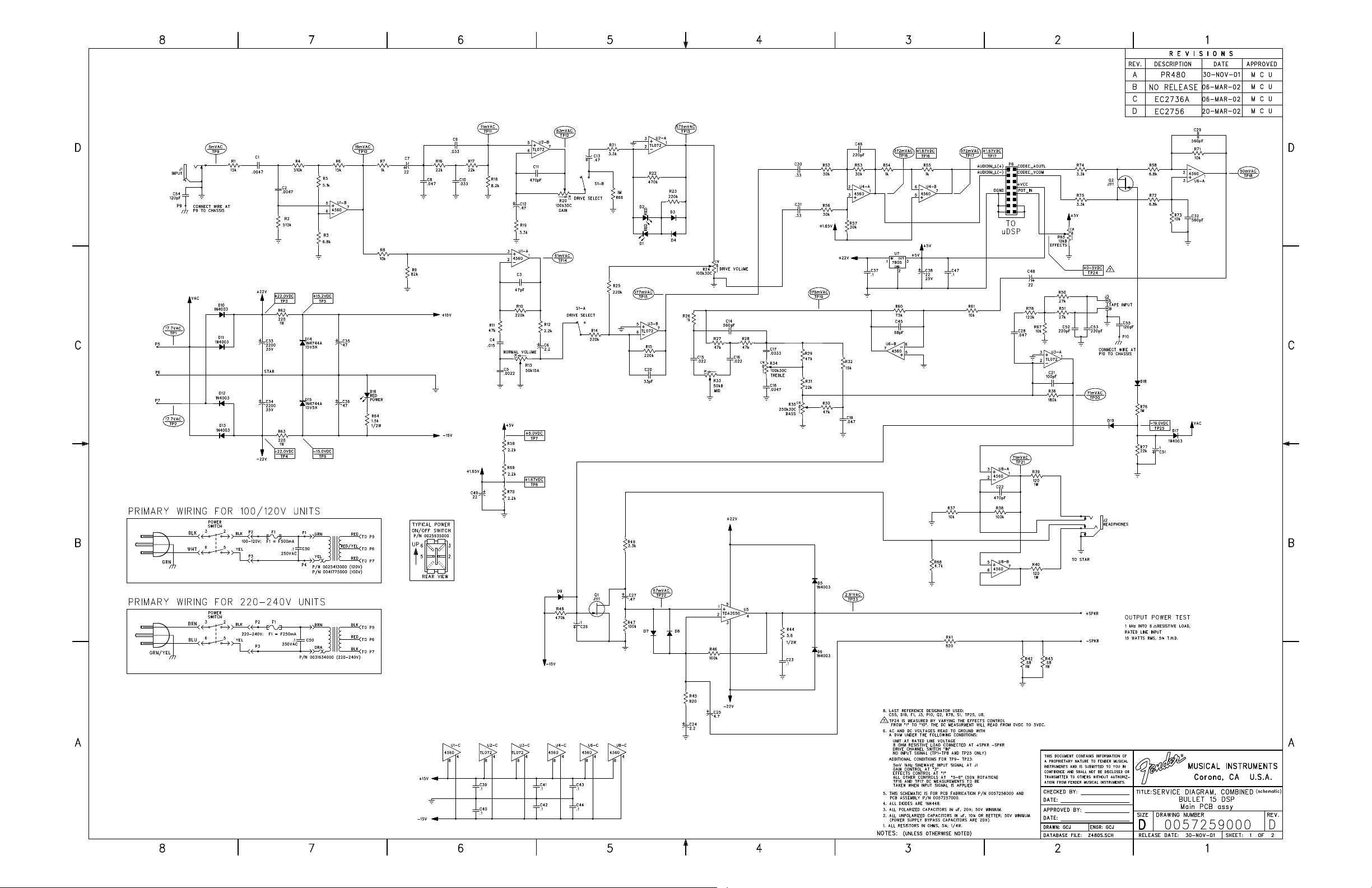
Circuit Description............. 5
Parts Lists:
PCB Assembly............ 6
uDSP Assembly ......... 8
Chassis Assembly ...... 8
Cabinet Assembly ...... 9
End Item Assembly .... 9
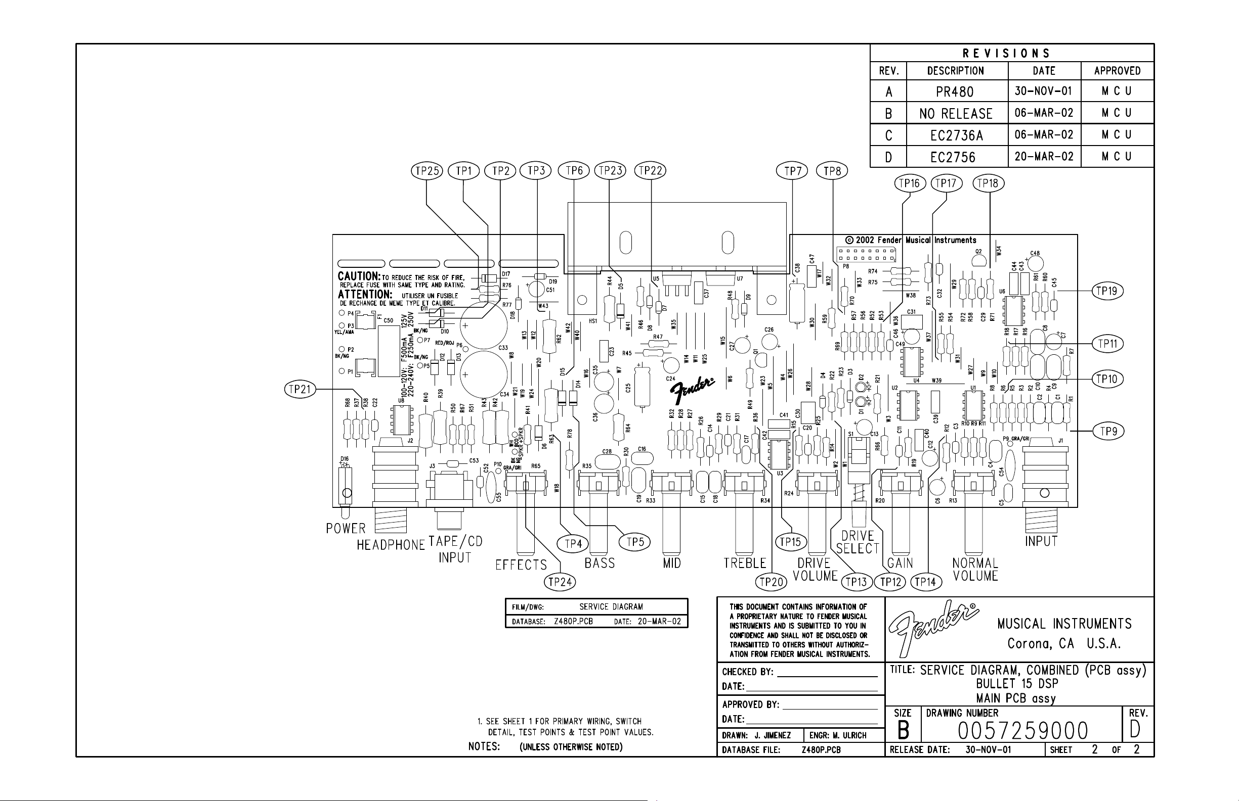
Service Diagrams ........... 10
Fender® Musical Instruments Corp. 8860 East Chaparral Road Suite 100 Scottsdale, AZ 85250
Page 2
June, 2002
IMPORTANT NOTICE
2
BULLET® 15 DSP
(This is the model name for warranty claims)
Copyright © 2002 FMIC. All rights reserved. All
information contained herein is CONFIDENTIAL
and PROPRIETARY and is the property of Fender®
Musical Instruments Corporation. It is not to be
sold or assigned to another party and is disclosed
solely for use by Fender Authorized Service Centers for purposes of product service and
maintenance. All information is not to be disclosed
to others without the expressed permission of
Fender® Musical Instruments Corporation. All
PARTS LIST CODES
The description codes used in the itemized Parts Lists are defined below:
CAPACITOR CODES
CAP AE = Aluminum Electrolytic
CAP CA = Ceramic Axial
CAP CD = Ceramic Disk
CAP MPF = Metalized Polyester Film
CAP MY = Mylar
CAP PFF = Polyester Film/Foil
RESISTOR CODES
RES CC = Carbon Comp
RES CF = Carbon Film
RES FP = Flame Proof
RES MF = Metal Film
RES WW = Wire Wound
specifications are subject to change without notice.
This information and any copies produced electronically or otherwise must be surrendered upon
demand of Fender Musical Instruments Corporation.
Parts marked with two asterisks (
quired use of that specific part. This is necessary
for RELIABILITY and SAFETY requirements.
DO NOT USE A SUBSTITUTE!
HARDWARE CODES
BLX = Black Oxide
CR = Chrome Plated
HWH = Hex Washer Head
M = Machine Screw
NI = Nickel Plated
OHP = Oval Head Phillips
PB = Particle Board
PHP = Pan Head Phillips
PHPS = Pan Head Phillips Sems
SMA = Sheet Metal "A" Point
SMB = Sheet Metal "B" Point
SS = Stainless Steel
TF = Thread Forming
ZI = Zinc Plated
) indicate the re-
**
Page 3

SPECIFICATIONS
Model Name: Bullet 15 DSP
Release Number: PR 241
(Not a model number)
Part Numbers (120V, 60Hz) US: 2267700020
(110V, 60Hz) TW: 2267701020
(240V, 50Hz) AUS: 2267703020
(230V, 50Hz) UK: 2267704020
(230V, 50Hz) ARG: 2267705020
(230V, 50Hz) EUR: 2267706020
(100V, 50/60Hz) JPN: 2267707020
(220V, 60Hz) ROK: 2267709020
3
BULLET® 15 DSP
(This is the model name for warranty claims)
Power Requirement: 38W
Power Output: 15W RMS into 8 ohms @ 5%THD
Nominal Input Level: 100mV for 15W into 8 ohms @ 5%THD
Impedances Input (Pre-Amp): 1M ohms
CD Input: greater than 30k ohms
Speaker Complement: One (1) 8", 8 ohm,
Fender Special Design Speaker
(P/N 0025421000)
Dimensions Height: 12.4 in (31.4 cm)
Width: 13.25 in (33.7 cm)
Depth: 7.13 in (18.1 cm)
Weight: 15 lbs (6.8 kg)
Product specifications are subject to change without notice
Page 4
(This is the model name for warranty claims)
SERVICE NOTES
4
BULLET® 15 DSP
1. CHASSIS REMOVAL is accomplished by first
removing four (4) screws from the Rear Cabinet Panel and two (2) screws from the top of
the Cabinet; detach the speaker wires from the
speaker and then slide the Chassis toward the
rear of the Cabinet.
2. uDSP PCB ASSEMBLY REMOVAL is accom-
plished by disconnecting the Ribbon cable on
the uDSP PCB Assembly, releasing the tabs on
each of the plastic Stand-offs which the uDSP
PCB Assembly is mounted. Removal of the
uDSP PCB Assembly may be necessary should
any of the Digital Effects operate improperly.
PCB EXCHANGE POLICY
Parts marked with a single asterisk (*) in the Part
Lists (starting on page 9) are not field replaceable.
If a failure due to one of these components is detected, please contact the Fender® Dealer
3. BULLET 15 DSP MAIN PCB REMOVAL is ac-
complished by removing the following items: All
Knobs, one (1) screw at the CD Input Jack, two
(2) nuts and washers at the Input and Headphone Jacks, two (2) screws at the Heatsink
which attaches to the Chassis. Desolder the
Transformer Leads at P1, P4, P5, P6 and P7.
Disconnect the Yellow and Black wires at the
Power Switch leading from P2 and P3. Disconnect the Ribbon Cable at P8.
Customer Service Department to order the complete PCB Assembly.
Page 5

CIRCUIT DESCRIPTION
5
BULLET® 15 DSP
(This is the model name for warranty claims)
This section provides an overview of any new or
unusual circuitry incorporated into this amplifier
model. The purpose is to aid the service technician
by providing insight into the design areas most
likely to present a challenge in troubleshooting.
This overview is focused for the efficient use and
security of Fender® proprietary information.
PRE-AMPLIFIER
The guitar input signal is fed into the high pass filter
at U1–B before splitting into two signal paths. The
Normal Channel signal path (U1–A to U3–B) is active until the Drive Select switch is pushed “IN” to
change the signal path from the Normal Channel to
the Drive Channel (U2–B to U3–B). Differential
amplifier U4–A and follower U4–B adjust the signal
level and provides +1.65VDC bias voltage to the
uDSP effects card. The preamp is in series with the
digital effects card, therefore, disconnecting the
card breaks the overall signal path. The signal from
the uDSP card is recovered at U6–A. It is necessary to bring the signal back to its level prior to
entering the uDSP card. This is accomplished by
increasing the signal gain at U6–B. The signal is
fed through the Passive Tone Control circuitry to the
summing amplifier at U3–A, where it is mixed with
the CD/Tape Input. The signal is fed through the
Headphone buffer amplifier (U8–A and U8–B) and
on to the Power Amplifier. FET Q2 is used to mute
U6–A at power shutdown, preventing any uDSP
card signal transients from getting through to the
Power amplifier.
POWER AMPLIFIER
Current Feedback topology is used for the Power
amplifier. The Power amplifier IC (U5) is configured
as a non-inverting amplifier. Diodes D7 and D8 are
used for common-mode protection of the amplifier.
Current feedback is achieved by sampling current
at the negative speaker terminal and feeding the
signal back to the inverting node of the Power amplifier through R41 and series capacitor C25. The
negative speaker terminal is referenced to ground
through resistors R42 and R43. FET Q1 provides a
mute function at the Power amplifier input.
POWER SUPPLY
Standard bridge rectifiers for high voltage (+/-22V),
with zener regulation (D14–15) for the +/–15V supplies. +15V supplies U7, 7805 regulator for +5V
supply for the uDSP card and digital user–interface.
DIGITAL USER INTERFACE
The uDSP Effects control (R65) is a linear pot that
sets a DC level (0–5V), which is read by an A/D
converter located on the uDSP card. These DC
levels determine which desired Effect is selected.
DIGITAL NOISE
The uDSP effects card generates some high frequency noise (>50kHz), which is a normal product
of DSP processing. This does not affect amplifier
performance, but may be visible when observing
the output of the amplifier on an oscilloscope.
.
Page 6
BULLET® 15 DSP
(This is the model name for warranty claims)
6
PARTS LIST:
QTY. PART # DESCRIPTION REFERENCE DESIGNATION
1 0057257004 PCB ASSY BULLET 15 DSP
1
1
REF 0057259000 SERV. DIA. COMB. BULLET 15 DSP
1
1
3
2
2
2
3
2
2
1
3
1
2
1
3
1
1
9
2
1
1
3
1
2
2
3
3
1
1
1
1
7
7
2
1
2
4
1
1
1
1
1
* **PCB FAB BULLET 15 DSP
*
*
*
*
*
*
*
*
*
*
*
*
*
*
*
*
*
***CAP MPF .1uF 250VAC 20%
*
*
*
*
*
*
*
*
*
*
*
*
*
*
*
*
*
*
*
*
*
*
*
*
*
HEATSINK BULLET 15 DSP
CAP AE AX 22uF 35V 20% C38
CAP AE AX 4.7uF 50V 20% C25
CAP AE RDL .47uF 50V 20% C12-13 C27
CAP AE RDL 1uF 50V 20% C26 C51
CAP AE RDL 2.2uF 50V 20% C6 C24
CAP AE RDL 2200uF 35V 20% C33-34
CAP AE RDL 22uF 50V 20% C7 CC48-49
CAP AE RDL 47uF 50V 20% C35-36
CAP CD 120pF 500V 5% C54-55
CAP CA 100pF 100V 5% C21
CAP CA 220pF 100V 5% C46 C52-53
CAP CA 33pF 50V 5% C20
CAP CA 470pF 50V 5% C11 C22
CAP CA 47pF 100V 5% C3
CAP CA 560pF 50V 5% C14 C29 C32
CAP CA 68pF 100V 5% C45
CAP MPF .1uF 63V 10% C23 C37 C39-44 C47
CAP MPF .33uF 63V 10% C30-31
CAP PFF RDL .0022uF 100V 10% C5
CAP PFF RDL .0033uF 100V 10% C17
CAP PFF RDL .0047uF 100V 10% C1-2 C18
CAP PFF RDL .015uF 100V 10% C4
CAP PFF RDL .022uF 100V 10% C15-16
CAP PFF RDL .033uF 100V 10% C9-10
CAP PFF RDL .047uF 100V 10% C8 C19 C28
CONTROL 100K 30C SNAP IN R20 R24 R34
CONTROL 10KB R65
CONTROL 250K 30C R35
CONTROL 50KB SNAP IN R33
CONTROL SNAPIN 50K 15A R13
DIODE 1N4003 D5-6 D10-13 D17
DIODE 1N4448 SIGNAL D3-4 D7-9 D18-19
DIODE ZEN 1n4744a 15v 1w 5% D14-15
HEADER .1 8x2 P8
IC DUAL OP AMP TL072 U2-3
IC DUAL OPAMP PC4560 U1 U4 U6 U8
IC OP AMP PWR TDA2050V U5
IC REGULATOR +5V MC7805CT U7
JACK MONO R/A J1
JACK PHONO DUAL PC MTG J3
JACK STEREO R/A W/SL J2
MAIN – PCB ASSEMBLY
C50
(continued)
* Non-serviceable part. Replace complete parent assembly. See PCB EXCHANGE POLICY on page 4.
Unique Fender® part. Order directly from the Fender® dealer Customer Service Department.
** Safety Requirement part. Replacement must match Safety Agency…–Value, if specified –Type, if specified –Approval Mark(s) if on part.
** Both a unique Fender® part and a Safety Requirement part as defined above.
Page 7
BULLET® 15 DSP
(This is the model name for warranty claims)
7
PARTS LIST:
QTY. PART # DESCRIPTION REFERENCE DESIGNATION
3
1
1
1
2
3
6
3
1
4
2
4
5
4
4
5
1
2
5
1
2
3
1
1
1
2
1
2
2
2
2
2
2
1
1
1
1
1
2
2
42
*
*
*
*
*
*
*
*
*
*
*
*
*
*
*
*
*
*
*
*
*
*
*
*
*
*
*
*
*
*
*
*
*
*
*
*
* **PCB WIRE SET, BULLET 15 DSP
*
*
***FUSE CLIP PCB 5MM
*
LED, RED LONG LEAD LUMEX D1-2 D16
SPACER LED .5x.1 BRN @ D16
RES CF 1/2W 1.5k 5% R64
RES CF 1/2W 5.6 ohm 5% R44
RES CF 1/4W 27k 5% R50-51
RES CF 1/4W 100k 5% R38 R46-47
RES CF 1/4W 10k 5% R8 R37 R61 R67 R71 R73
RES CF 1/4W 15k 5% R1 R6 R32
RES CF 1/4W 180k 5% R36
RES CF 1/4W 1k 5% R7 R26 R54-55
RES CF 1/4W 1M ohm 5% R66 R76
RES CF 1/4W 2.2k 5% R12 R59 R69-70
RES CF 1/4W 220k 5% R10 R14-15 R23 R25
RES CF 1/4W 22k 5% R16-17 R31 R77
RES CF 1/4W 30k 5% R52-53 R56-57
RES CF 1/4W 3.3k 5% R19 R21 R49 R74-75
RES CF 1/4W 4.7k 5% R68
RES CF 1/4W 470k 5% R22 R48
RES CF 1/4W 47k 5% R11 R27-30
RES CF 1/4W 5.1Kohm 5% R5
RES CF 1/4W 510Kohm 5% R2 R4
RES CF 1/4W 6.8k 5% R3 R58 R72
RES CF 1/4W 75k 5% R60
RES CF 1/4W 8.2k 5% R18
RES CF 1/4W 82k 5% R9
RES CF 1/4W 820ohm 5% R41 R45
RES CF 1/4W 120k 5% R78
RES FILM 1W .68 ohm 5% R42-43
RES FILM 1W 120 ohm 5% LL R39-40
RES FILM 1W 220ohm 5% R62-63
SCRW M 4-40x3/8 PHP BLX @ U5 U7
SCRW TF 6-32x3/8 PHP ZI @ HEATSINK
NUT HEX 4-40 EX LOCK @ U5 U7
INSULATOR MICA TO-220 @ U5
SWITCH PUSH SLFLK SHORT STROKE S1
BUTTON PUSH OFF WHITE @S1
WSHR SHLDR NYL 1/8x1/4 @ U5
XSTR N-CH JFET J111 TO-92 Q1-2
JUMPER WIRE 22 GA W1-21 W23-43
MAIN – PCB ASSEMBLY
F1
(continued)
* Non-serviceable part. Replace complete parent assembly. See PCB EXCHANGE POLICY on page 4.
Unique Fender® part. Order directly from the Fender® dealer Customer Service Department.
** Safety Requirement part. Replacement must match Safety Agency…–Value, if specified –Type, if specified –Approval Mark(s) if on part.
** Both a unique Fender® part and a Safety Requirement part as defined above.
Page 8
BULLET® 15 DSP
(This is the model name for warranty claims)
8
PARTS LIST:
QTY. PART # DESCRIPTION REFERENCE DESIGNATION
1 0057261008 PCB ASSY uDSP BULLET 15 DSP w/EPROM
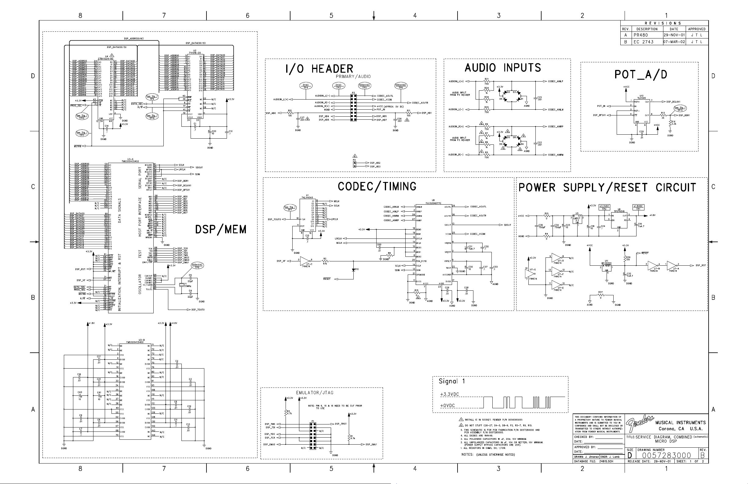
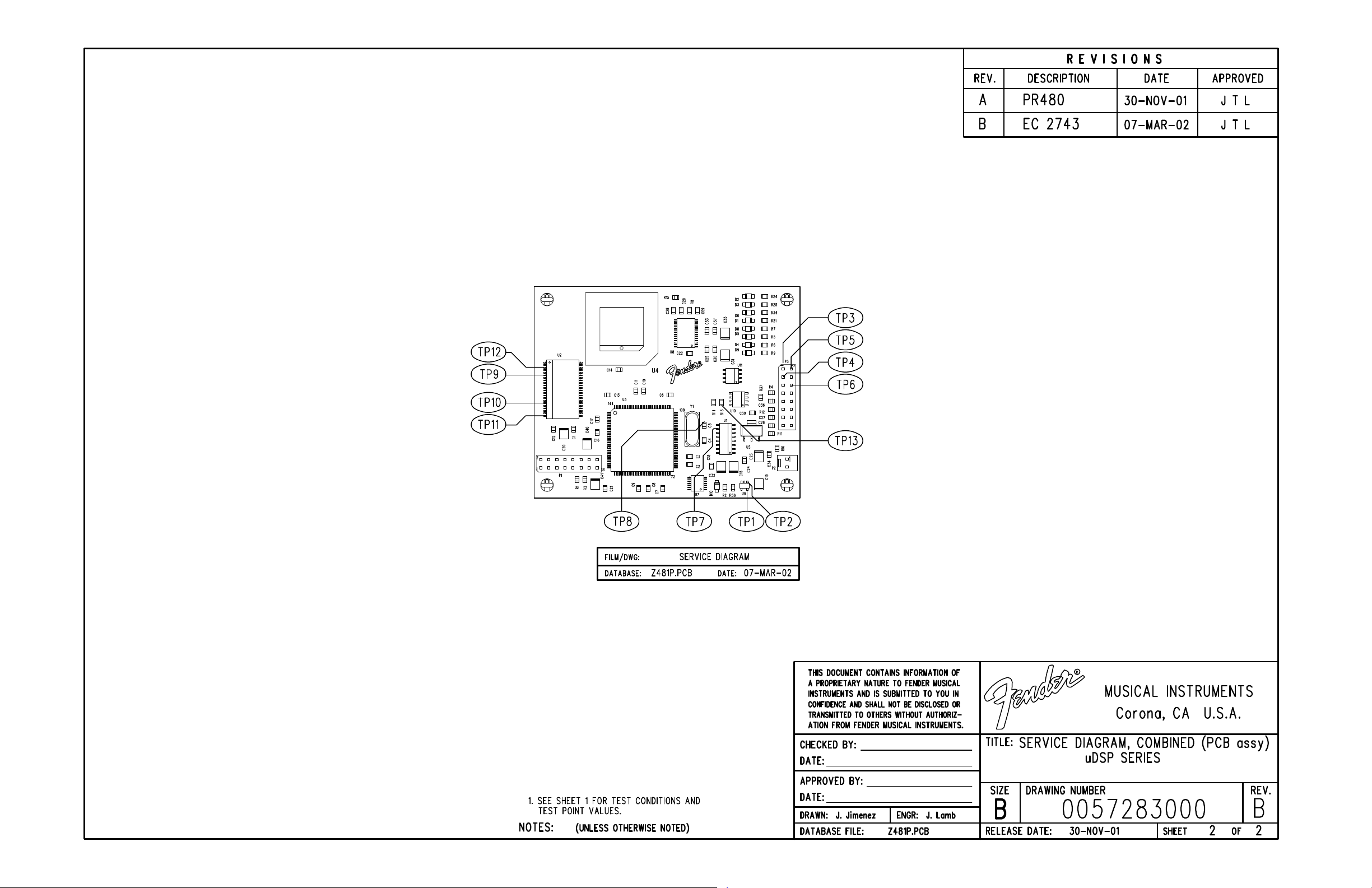
REF 0057283000 SVC DIAG COMB MICRO DSP
1
1
2
14
10
2
2
3
6
5
2
4
2
4
4
1
1
2
1
1
1
1
1
1
1
1
1
1
1
1
1
*
*
*
*
*
*
*
*
*
*
*
*
*
*
*
*
*
*
*
*
*
*
*
*
*
*
*
*
*
*
*
IC ROM BULLET 15 DSP V1.01
PCB FAB uDSP
CAP 0805 CER .001uF 25V 5%
CAP 0805 CER .01uF 25V 5%
CAP 0805 CER .1uF 25V 5%
CAP 0805 CER 22pF 25V 5%
CAP 0805 CER 750Pf 25v 5%
CAP 3528 TAN 4.7uF 16V 20%
CAP 3528 TAN 10uF 16V 20%
DIODE SMT 1N4448 SIGNAL
HDR .1 CTR 8x2 CKT SQ PIN
RES 0805 MF 1/10W 5% 0ohm
RES 0805 MF 1/10W 5% 100ohm
RES 0805 MF 1/10W 5% 750ohm
RES 0805 MF 1/10W 5% 1k
RES 0805 MF 1/10W 5% 2k
RES 0805 MF 1/10W 5% 3.3k
RES 0805 MF 1/10W 5% 4.7k
RES 0805 MF 1/10W 5% 15k
RES 0805 MF 1/10W 5% 47k
IC SMT SOCKET PLCC 44-TT
IC SMT TLC549 AD
IC SMT SRAM 64Kx16
IC SMT COUNTER 74LV4040
IC SMT HEX SCHMITT-T INV 74HC14
IC SMT VREG +3.3V LM1117
IC SMT CODEC TLC320AD77C
IC SMT DSP TMS320VC5402PGE
IC SMT VREG +1.8V 150mA TPS76318
IC SMT RESET 5V MC34064D-5
XTAL 20MHz HC49SD
uDSP – PCB ASSEMBLY
(continued)
PARTS LIST:
QTY. PART # DESCRIPTION REFERENCE DESIGNATION
1
1
- 0041775000
1 0025413000
- 0031634000
1 0025935000
6 0053986000 KNOB RTRY SS W/CHR INSERT @ R13 R20 R24 R33-35
1 0057256000 KNOB RTRY ARROW W/CHR INS @ R65
5 0026459000 WSHR FLAT 6x3/8 ZI @ XFMRS, HEATSINK, PWR CORD
5 0028684000 SCRW SMB 6x3/8 PH PHS BLX @ XFMRS, HEATSINK, PWR CORD
2 0053479000 NUT HEX 7/16 20X1/8 NI @J1-2
2 0053480000 WASHER FLAT .442 X.692 NI @J1-2
1 0038900000 SCRW TF 6-32X1/4 PHP ZI @ GND
1 0048377000
- 0020781000
1
1 0051330000
** Safety Requirement part. Replacement must match Safety Agency…–Value, if specified –Type, if specified –Approval Mark(s) if on part.
** Both a unique Fender® part and a Safety Requirement part as defined above.
*
*
*
* Non-serviceable part. Replace complete parent assembly. See PCB EXCHANGE POLICY on page 4.
Unique Fender® part. Order directly from the Fender® dealer Customer Service Department.
CHASSIS BULLET 15 DSP AMP
CLAMP CABLE NYL SCRW MNT 5/16 @ 100V-120V PWR CORDS
**XFMR PWR EXPORT 100v
**XFMR PWR F1158UC MEX AMPS/BRNC
**XFMR PWR FD15 230v
**SWITCH DPST .187 TAB (DOM)
**FUSE QA 20mm X 5mm 250V .5A
**FUSE QA 20mmx5mm 250v .25A
PANEL FRONT BULLET 15 DSP
**CABLE ASSY 120V 6 FT
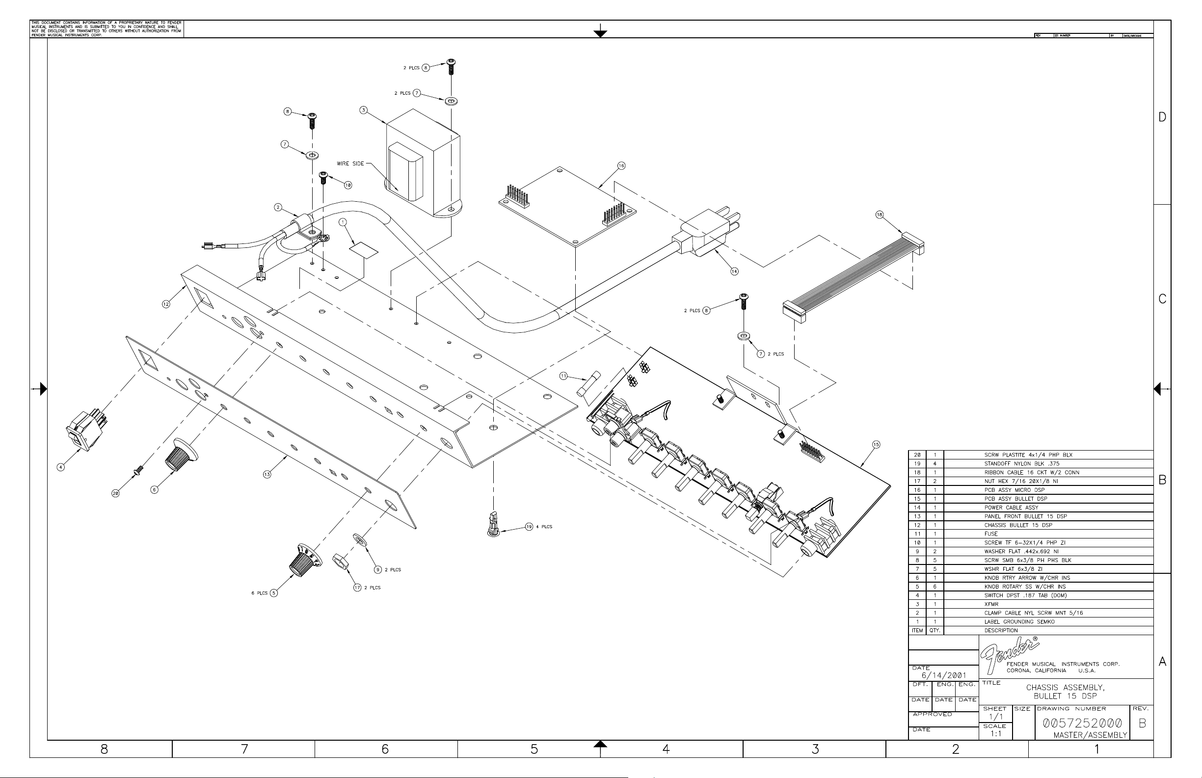
CHASSIS ASSEMBLY
100V XFMR
120V XFMR
220V-240V XFMR
POWER SWITCH, ALL MODELS
100V-120V FUSE
220V-240V FUSE
(continued)
Page 9
BULLET® 15 DSP
(This is the model name for warranty claims)
9
PARTS LIST:
QTY. PART # DESCRIPTION REFERENCE DESIGNATION
- 0040992000
- 0026528000
- 0036479000
- 0048465000
- 0057675000
1 0057359000 CABLE RIBBON 16 CKT W/2 CONN
4 0051404000 STANDOFF NYLON BLK .375 @ uDSP
1 0031868000 SCRW PLASTITE 4x1/4 PHP BLX @ J3
-
*
**CABLE ASSY PWR 5A U.K..187 TAB
**CABLE ASSY PWR 230v .187 TAB
**CABLE ASSY PWR AUST .187 TABS
**CABLE ASSY PWR .187 100V
**CORD PWR ARG .187 TABS
CLAMP CABLE NYL SCRW MNT 1/4 @ 230V-240V PWR CORDS
PARTS LIST:
QTY. PART # DESCRIPTION REFERENCE DESIGNATION
12 0026571000 SCRW SMAB 8X5/8 THP NI @ CORNERS
4 0029071000 CORNER NOTCHED NICKLE (FD)
0.910
4 0029323000 FOOT RUBBER 1.0 DIA SMALL
2 0026566000 CORNER 2 HOLE w/TAB NI
0.003
*
*
TOLEX "BRAVURA BLACK"
TAPE ALUM 5" x 60 YDS
PARTS LIST:
QTY. PART # DESCRIPTION REFERENCE DESIGNATION
1 0025421000 SPKR 8" PF8643 (099-4808-002)
5 0029828000 SCRW PB 8x3/4 PHP ZI @ SPKR & CABLE CLAMP
1 0057262000 MANUAL OWNERS BULLET 15 DSP
1 0057254000 LABEL REAR BULLET 15 DSP
- 0057255000 LABEL REAR ROK BULLET 15 DSP
1 0029906000 NAMEPLATE FENDER GENERIC SMALL @ BAFFLE ASSY
2 0018113000 SCRW SMA 4x1/2 OHP BLX @ LOGO
2 0025395000 HANDLE CAP 1 HOLE NI (DWG 17420) @ HANDLE
1 0025883000 HANDLE SHORT NO LOGO
2 0022277000 SCRW M 10-32x1-1/2 OHP NI @ HANDLE
1 0057763000 CAB ASSY BULLET 15 DSP
1 0050711000 CAB BACK LAMTED BLK PB 3/8"
1 0040143000 GRILLE ASSY BLK/SLVR X-15 '92
4 0029677000 SCRW SMA 6x1 THP BLX @ CAB BACK
1 0022491000 CLAMP CABLE NYL SCRW MNT 5/16 @ PWR CORD & CAB
1 0022327000 WSHR FLAT 8x7/16 NI @ CABLE CLAMP
2 0029527000 WSHR FNSH 8-5/8 FLNGD BLX WX @ CAB SIDE
2 0026800000 SCRW SMAB 8x1-3/4 OHP BLX @ CAB SIDE
0.2 0029085000 VELCRO STRIP LOOP 1.5" WD BLK @ CAB BACK
0.2 0029086000 VELCRO STRIP HOOK 1.5" WD BLK @ CAB BACK
CHASSIS ASSEMBLY
CABINET ASSEMBLY
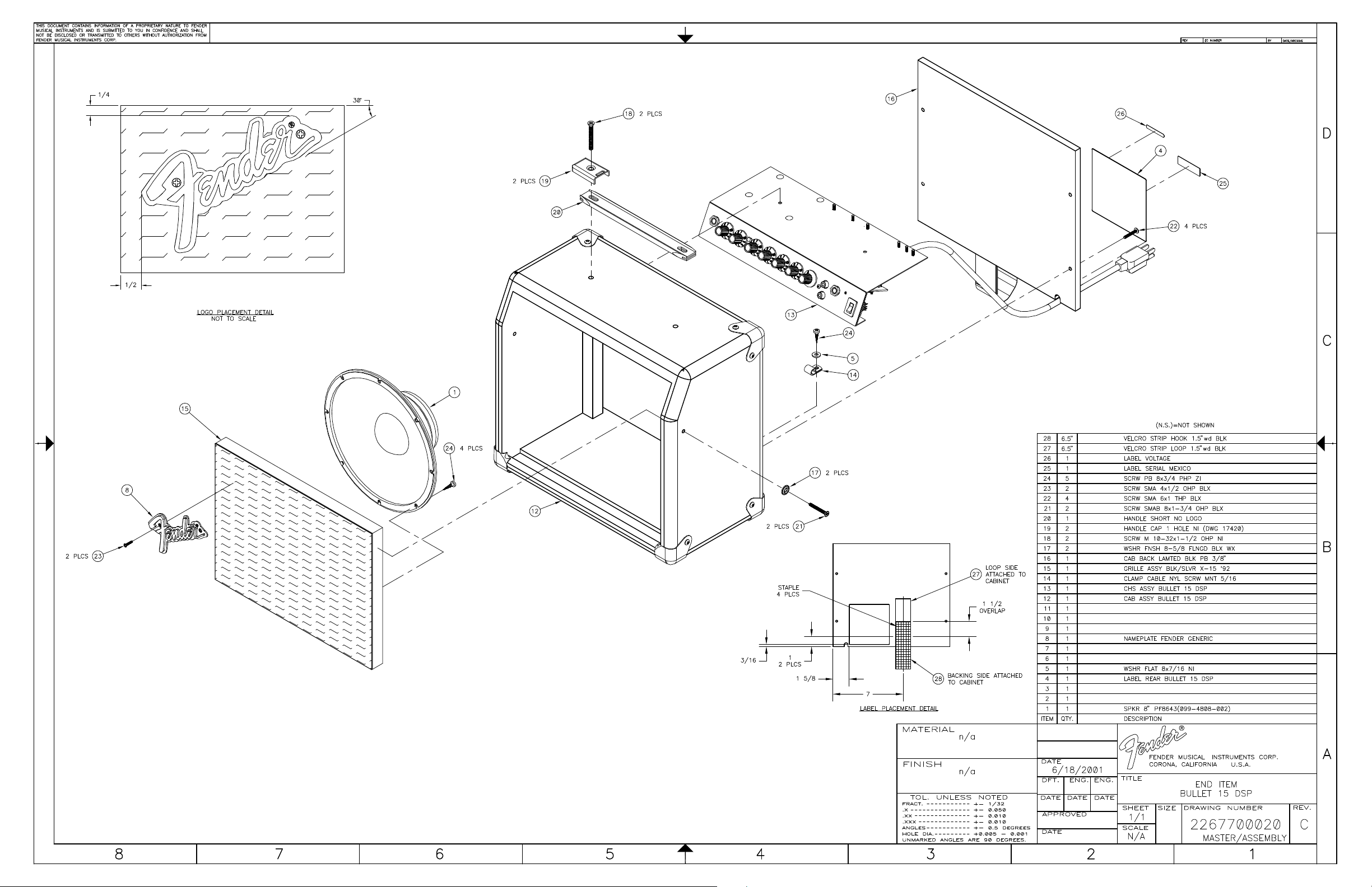
END ITEM ASSEMBLY
(continued)
(continued)
(continued)
* Non-serviceable part. Replace complete parent assembly. See PCB EXCHANGE POLICY on page 4.
Unique Fender® part. Order directly from the Fender® dealer Customer Service Department.
** Safety Requirement part. Replacement must match Safety Agency…–Value, if specified –Type, if specified –Approval Mark(s) if on part.
** Both a unique Fender® part and a Safety Requirement part as defined above.
Page 10

BULLET® 15 DSP
(This is the model name for warranty claims)
Schematics and Drawings
Service Diagram (Schematic) ............Bullet 15 DSP
Service Diagram (PCB Assy) ............Bullet 15 DSP
Service Diagram (Schematic) ............Micro DSP
Service Diagram (PCB Assy) ............Micro DSP
Chassis Assy ............Bullet 15 DSP
End Item Assy ............Bullet 15 DSP
10
Page 11
Page 12
Page 13
Page 14
Page 15
D
Page 16
D
 Loading...