


RS114

INSTALLATION GUIDE
•
OWNER’S GUIDE
REMOTE STARTER
MODELS RS1100/RS1100E, RS114
CONTENTS
System Features....................................... 1
System Components ..................................... 1
Required Tools........................................ 1
Technical Assist ance .................................. 1
Before You Begin...................................... 2
Precautions........................................... 2
Using your T est Probe ................................. 2
Making Connections .................................... 3
Locating & Making Connections........................ 4-6
Neutral Safety Switch ................................. 6
Connecting Wiring Harness ............................. 6
Antenna Placement ..................................... 7
Anti-Theft System ..................................... 7
Optional Features ................................... 7-9
Operator Programming Instructions ................... 9-10
How to use Y our Remote Transmitter.................. 1 0-11
Technical Assistance
All tech personnel are expertly qualified to answer any technical questions.
Technicians are available Monday through Friday from 9:00 a.m. until 8:00 p.m. and Saturday 10:00 a.m. until 4:00 p.m.
Address
288 Canton Avenue • Wintersville, Ohio 43953
Telephone
Phone: 740-264-4710 • 800-878-8007 • Fax: 740-264-7306

SYSTEM FEATURES
Four-Button Extended Range Remotely start your car to run the heater, air conditioning or defroster from an extended
Remote Control distance.
Keyless Entry Remotely locks and unlocks your power door locks.
Tr unk Release/Sliding Door Remotely open your po wer trunk or your po wer sliding v an door with a push of a button.
Remote Programmable Run T ime Remotely program your vehicle to run 5 to 15 minutes.
Run T ime Confirmation Remotely check the programmed run time of 5, 10 or 15 minutes.
Tach/T achless Option A programmable feature that lets you choose from the easy to install tachless operation or
Parking Light Confirmation Confirms that your vehicle has received a remote signal and will remain on if the engine is
Dome Light Supervision Never walk up to a dark vehicle again. When unlocking the doors by remote control, the dome
Cold Start Remotely program your car to start at a preset temperature. Automaticall y starts y our car in
Pit Stop Mode Allows you to exit the vehicle while the engine remains running without leaving the key in
Extended Range Allows you to operate your system from up to 400 feet away . (800 feet for E Models)
Code Learning Allows your remote starter to learn new remotes, should you want to add remotes, or if remotes
Limited Lifetime Warranty Guarantees life-long protection.
the wire-in, tach operation.
remotely started.
light will come on and stay on for 1 minute. This feature will shut off when you activate the
ignition switch or step on the brake.
freezing temperature so you never have a dead battery.
the ignition switch.
are lost.
SYSTEM COMPONENTS
Y our system includes:
1- Four Button Remote Transmitter
1- Main Control Module
1- 16-Pin Wire Harness
1- 5-Pin Door Lock Harness
6- Heavy Gauge Wires w/ Spade Connectors
1- Hood Pin Switch
1- Extended Range Antenna (E Models Only)
2- Window Antenna Clips (E Models Only)
1- Warranty
1- Warning Sticker for Under the Hood
2-Bulldog Window Decals
1- Installation & Operation Guide
1- Bonus Installation Kit (with selected models)
REQUIRED TOOLS
Y ou may need a 5/16 inch drill bit when mounting the hood pin switch. In most cases no additional tools
are required, however if the bottom of your dash on the driver’s side will come off you must remove it.
In this case a screwdriver or wrench may be needed.
TECHNICAL ASSISTANCE
Should you need help. First check our website at www.bulldogsecurity.com for the most common installation
problems or then our toll-free Tech Support Hotline Monday through Friday 9AM-8PM and Saturday 10AM-4PM
EST at 800-878-8007.
Before you begin, check our website at www.bulldogsecurity.com for complete wiring information for your
vehicle.
Y ou must give the following information:
•Name
•Telephone Number with Area Code (Fax number if applicable)
•Year, Make, and Model of the vehicle
•The model of the system you are installing
•The type of assistance you are requesting
If you give the above information you will be called in the order your call was received.
1

BEFORE YOU BEGIN
Congratulations, you have purchased one of the most advanced remote starter systems ever made. Your new
remote starter is a technological breakthrough utilizing the most advanced, state-of-the-art technology
and components. It is computer controlled and manufactured in the U.S.A. The dependability and variety of
features make Bulldog Security the leader in the industry. Enjoy your new remote starter for years to
come!
This remote system is designed to start your vehicle by sending a command signal from the remote transmitter
or by programming automatic temperature start. It is required that your installation be done in a wellventilated area. It is the responsibility of the owner to ensure that the remote system is not used to
start the vehicle in an undesired location.
It is recommended that a carbon monoxide detector be installed in the living area near the location where
the vehicle may be garaged.
Since there are many different makes and models of vehicles, for a more complete wiring chart, visit our
website, www.bulldogsecurity.com to access your vehicle’s colors and location of wires.
Read this manual thoroughly BEFORE starting the installation. Most newer vehicles may have a factor y antitheft system. If you vehicle is equipped with this system, an additional module, Part #781 or #791, will
be required. Contact 800-659-0764 to order this item. Please do not skip any steps. Mount the control
module under the driver’s dash inside the vehicle after all connections have been made. Do not mount the
control module in the engine compartment.
TA CH/T ACHLESS OPERATION
In most cases the decision to go with tachless mode will save time during the installation. If your vehicle
is hard-starting then you should use tach mode.
MAKE SURE YOU PLACE THE WARNING STICKER UNDER THE HOOD.
PRECAUTIONS
This system is designed for use with vehicles equipped with fuel-injected,
gasoline engines with automatic transmissions only.
SAFETY FIRST!
Never remotely start your vehicle indoors, with the keys in the ignition or unless the transmission
is in park. A periodic safety check is recommended to ensure that your system is in proper working
order.
DO NOT use mechanical wiring connections, such as crimp or snap together wire connectors.
Instead, follow the instructions on page 3-4.
DO NOT disconnect the battery if the vehicle has an anti-theft-coded radio or is equipped with
an airbag. Doing so may cause a warning light to be displayed which may require a trip to the
dealer to be corrected.
DO NOT leave the interior or exterior lights on for an extended period of time as it may cause
battery drain. Remove the dome light fuse from the vehicle’s fuse box. N OTE: Starter systems do
not work well with a partially discharg ed battery .
All General Motors rear wheel drive vehicles and Dodge Dakotas built prior to 1996 do not have
GENERAL MOTORS REAR WHEEL DRIVE VEHICLES AND DODGE DAKOTAS
an electrical neutral safety switch. They have a mechanical neutral safety switch. The mechanical
neutral safety switch operates as follows.
a)The key will only turn to the start position when the gear selector is in park or neutral.
b)The key can only be removed from the ignition switch when the gear selector is in the park
position.
You must use special precautions with this system.
WARNING!
USING YOUR TEST PROBE
To operate your test probe, connect the black clip to a good chassis ground. Connect the red clip to a good
12V positive source. If the test probe is connected correctly, both the green and the red lights will be dimly
illuminated. If a positive source is probed, the red light will glow bright and the green light will go out.
If a negative source is probed, the green light will glow bright and the red light will go out.
2
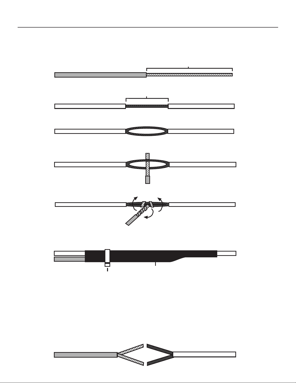
MAKING WIRING CONNECTIONS
NOTE: In most cases you should not cut your vehicle wire in two.
1. Strip back two inches of insulation on the wire from the remote starter.
T wo Inches of Bare Wire
2. Strip back one inch of insulation on the wire you need to connect to.
One Inch of Bare Wire
3. Separate the vehicle wire as shown. Make the separation large enough to fit the other
wire through.
4. Insert the wire(s) from the starter through the hole as shown. If two or more wires
are inserted, wrap them in opposite directions.
5. Wrap the wire around one side then the other and finally around itself as shown.
1
2
3
6. Use electrical tape to wrap. Be sure to cover the wire about two inches on either side
of the connection. First pull the wire that you have just connected along side the wire
you connected to, tape and wire tie them together. Use this method for all connections.
Wire Tie
CAUTION: All wires must be wrapped with tape and wire tied.
Electrical Tape
MAKING END TO END CONNECTIONS
Use this method ONLY when connecting two separate wires end to end.
1. When tying two separate wires together at their ends, strip back one inch of insulation on
both wires and separate the strands of wire as shown below.
3
 Loading...