

Page 1

INSTALLATION GUIDE
•
OWNER’S GUIDE
REMOTE STARTER IMMOBILIZER • SILENT GUARD
CONTENTS
System Features ......................................1
System Components ....................................1
Required Tools .......................................1
Technical Assistance .................................1
Before You Begin .....................................1
Precautions ........................................1-2
Making Connections .................................2-3
Locating and Making Connections ....................3-4
Antenna Placement ....................................4
How to use Your Remote Transmitter ...................4
OEM Wiring Chart .....................................5
Technical Assistance
All tech personnel are expertly qualified to answer any technical questions.
Technicians are available Monday through Friday from 9:00 a.m. until 8:00 p.m. and Saturday 10:00 a.m. until 4:00 p.m.
Address
288 Canton Avenue • Wintersville, Ohio 43953
Telephone
Phone: 740-264-4710 • 800-878-8007 • Fax: 740-264-7306
Page 2

SYSTEM FEATURES
Tw o-Button Extended Range Remotely immobilize your car’s engine from an extended distance.
Remote Control
V alet Mode Remotely turn your immobilizer on and off.
Limited Lifetime Warranty Guarantees life-long protection.
SYSTEM COMPONENTS
Y our system includes:
1-Installation & Operation Guide
1-Main Control Module and Harness
2-Two Button Remote Transmitters
1-High luminescence L.E.D. status indicator
REQUIRED TOOLS
Y ou will need a computer-friendly test light, electrical tape, extra 16 awg wire and wire strippers or
cutters.
TECHNICAL ASSISTANCE
Should you need help. First check our website at www.bulldogsecurity.com/wires.htm or call our toll-free
Tech Support Hotline Monday through Friday 9AM-8PM and Saturday 10AM-4PM EST at 800-8 78-8007 .
Y ou must give the following information:
•Name
•Telephone Number with Area Code (Fax number if applicable)
•Year, Make, and Model of the vehicle
•The model number of the system you are installing
•The type of assistance you are requesting
If you give the above information you will be called back as soon as possible, usually within 10 minutes.
BEFORE YOU BEGIN
Congratulations, you have purchased the most advanced remote control immobilizer system ever made. Your
new system is a technological breakthrough utilizing the most advanced state of the art technology and
components. It is computer controlled and manufactured in the U.S.A. The dependability and variety of
features make Bulldog Security the leader in the industry. Enjoy your new system for years to come!
We recommend you read this installation manual thoroughly before starting the installation. This manual
will supply you with time-sa ving information. Each step will guide you to a correct installation.
Y ou will need to decide where you will be placing the L.E.D. before you begin the installation.
Since there are many different makes and models of vehicles, it is impossible for this manual to cover
every wiring configuration. Instead, this manual will help you determine the correct connections and testing
procedures for your vehicle.
PRECAUTIONS
SAFETY FIRST!
A periodic safety check is recommended to ensure that your system is in proper working order.
DO NOT use mechanical wiring connections, such as crimp or snap together taps. Follow instructions on
pages 6-8.
DO NOT disconnect the battery if the vehicle has an anti-theft-coded radio or is equipped with an airbag.
Doing so may cause a warning light to be displayed and may require a trip to the dealer to be corrected.
1
Page 3
DO NOT leave the interior or exterior lights on for an extended period of time as it may cause battery
drain. Remove the dome light fuse from the vehicle’s fuse box.
DO NOT mount the control module until all connections have been made and tested. Using wire ties or double
sided tape MOUNT THE MODULE UNDER THE DRIVER’S DASH.
TESTING YOUR WIRES
When testing for a positive or negative voltage, you must use a computer friendly test light (logic probe)
or a volt/ohm meter. Make sure to probe and test each wire before making your connections.
MAKING WIRING CONNECTIONS
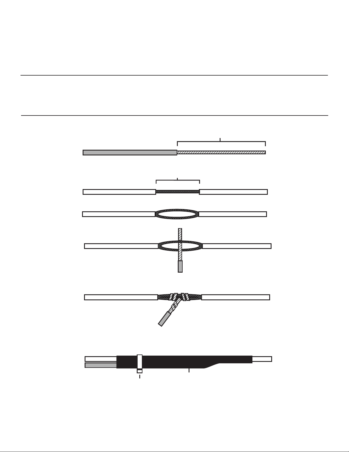
1. Strip back two inches of insulation on the wire from the keyless entry.
T wo Inches of Bare Wire
2. Strip back one inch of insulation on the wire you need to connect to.
One Inch of Bare Wire
3. Separate the vehicle wire as shown. Make the separation large enough to fit the other wire
through.
4. Insert the wire from the unit through the hole as shown.
5. Wrap the wire around one side then the other and finally around itself as shown.
1
2
3
6. Use electrical tape to wrap. Be sure to cover the wire about two inches on either side of the
connection. First pull the wire that you have just connected along side the wire you connected
to, tape and wire tie them together. Use this method for all connections.
Wire Tie
Electrical Tape
CA UTION: All wires must be wrapped and taped.
MAKING END TO END CONNECTIONS
FOLLOW THESE INSTR UCTIONS
2
Page 4
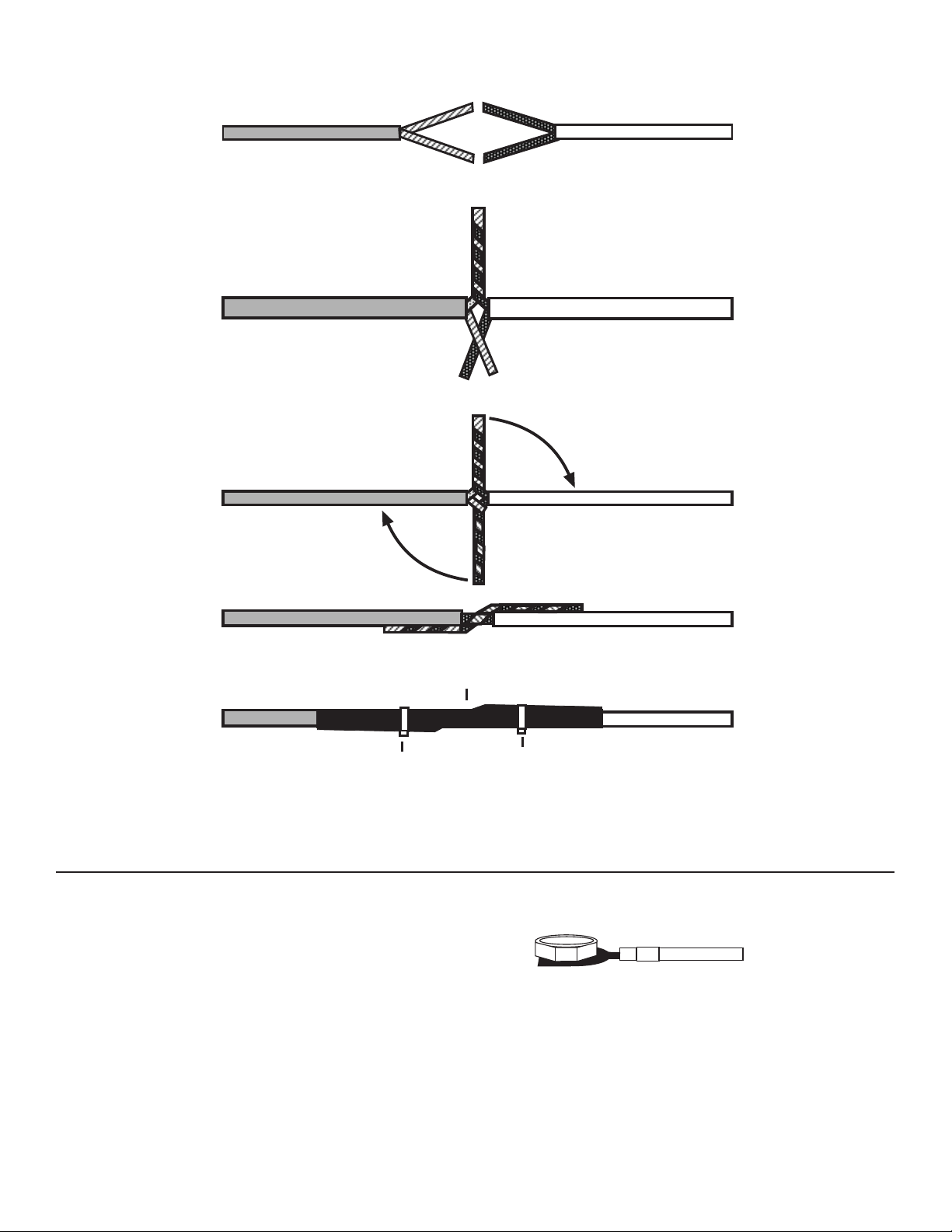
1. When tying two separate wires together at their ends, strip back 1” of insulation on both
wires and separate the strands of wire as shown below.
2. T wist upper wires together, twist lower wires together as shown.
3. Lay upper twisted pair of wires over right wire as shown. Bring lower twisted pair of wires
up to meet the left wire as shown.
4. Use electrical tape to wrap, be sure to cover about 2 inches on either side of connection.
Secure with wire ties as shown.
Wire Tie
Electrical Tape
Wire Tie
Use this method ONLY when connecting two separate wires end to end.
LOCATING & MAKING CONNECTIONS
GROUND
Connect the ground wire #7 to a clean unpainted metal surface under the dash.
Factory Bolt
12 VOL T CONSTANT
Connect the wire marked #8 (constant +12 volts) to constant 12 volts located at the ignition harness.
NOTE: Silent Guard will emit a series of chirps to indicate the unit is powered up.
IGNITION INPUT / IGNITION OUTPUT
Locate the primary factory ignition wire located at the ignition harness near the steering wheel column,
cut in two. Connect the wire marked #1 (ignition input) to the vehicle’s factory ignition wire leading
from the ignition key side. Connect the wire #4 (ignition output) to the other half of the factory
ignition wire.
Wire #7
Note: Remove any paint from
under bolt.
3
Page 5

STARTER INPUT / ST AR TER OUTPUT
Locate the crank (starter solenoid) wire in the ignition harness, cut in two. Connect the wire marked
#2 (starter input) to the vehicle’s factory crank wire from the ignition key side. Connect the wire
marked #5 (starter output) to the other half of the factory crank wire leading out to the starter solenoid
(engine).
FUEL INPUT / FUEL OUTPUT
Locate the fuel pump power wire, in some vehicles you can find this wire located at the factory fuse
panel, it will be labeled fuel pump or injectors. If your vehicle doesn’t have this, please refer to
your vehicle’s wire schematic. Once you locate the wire, cut it in two. Connect wire #3(fuel pump input)
to the 12 volt supply going to the fuel pump ignition key side. Connect wire #6 (fuel pump output) to
the half of the factory fuel pump wire leading out to the fuel pump.
L.E.D.
Locate a good spot for the L.E.D., visible from all sides of the vehicle. If you wish to drill a hole,
use a 5/16 inch drill bit to mount the L.E.D. If you or your customer wishes not to have the L.E.D.
permanently mounted, use the included double-sided adhesive L-bracket to mount the L.E.D.
ANTENNA PLACEMENT
ANTENNA
For best results, run the antenna (small gauge unmarked wire
from the front of the unit) as straight as possible. Do not
place the antenna next to any metal parts or the vehicle’s
main computer control module.
MODULE
3
L.E.D.
FUEL INPUT
FUEL OUTPUT
IGNITION INPUT
IGNITION OUPUT
STARTER INPUT
STARTER OUTPUT
ANTENNA
GROUND
HO W TO USE Y OUR REMOTE TRANSMITTER
Disarm
T o be able to start the vehicle, press and release Button
1
2
Disarm/Valet Off
BUTTON #2
Vale t On
BULLDOG
Enter Valet Mode
Press and hold Button #2 for 5 seconds. The LED will light up constantly and the Silent Guard will emit two
chirps. While in valet mode, the Silent Guard will constantly chirp when the ignition is in the ON position.
BUTTON #1
#1. The LED will stop flashing and the Silent Guard will
emit one chirp. After disarming the unit, a 30 second window
will open to allow the user to start the vehicle. If the
vehicle is not started within 30 seconds the unit will
automatically immobilize your vehicle. After this 30 second
window has expired, and the LED will flash.
Arm
The Silent Guard is designed to automatically arm 30 seconds
after the ignition is turned off, unless the system is in
valet mode.
8752416
+12 VOL T CONST ANT
Exit V alet Mode
Press and release Button #1. The LED will shut off and the Silent Guard will emit one chirp. The Silent Guard
will automatically arm in 30 seconds.
4
Page 6

OEM WIRING CHART
MAKE CONST. 12V+ STARTER IGN 1 IGN 2 IGN 3 ACCESS. LOCATION
GM RED YELLOW PINK WHITE GREEN ORANGE IGN. HARNESS
FORD CORP. YELLOW RED/BLUE RD/L.GRN BLK/GRN RED/BLK GRAY/YEL IGN. HARNESS
CHRYSLER CORP.RED YELLOW BLUE BLK/WHT N/A BLK/OR IGN. HARNESS
HONDA CORP. WHITE BLK/WHT BLK/YEL YELLOW N/A BLK/WHT IGN. HARNESS
MAZDA BLACK BLK/YEL BLK/WHT BLK/RED N/A BLUE IGN. HARNESS
MITSUBISHI RED/BLACK BLK/YEL BLK/WHT BLUE/BLK N/A BLUE IGN. HARNESS
NISSAN CORP. WHITE/RED BLK/YEL BLK/RED BLK/PNK N/A WHT/BLUE IGN. HARNESS
SUBARU BLK/YELLOW BLK/YEL BLACK BLUE N/A BLUE IGN. HARNESS
BLK/WHITE RED/YEL
TOYOTA CORP. WHITE BLK/WHT BLK/OR BLK/YEL N/A BLUE/RED IGN. HARNESS
WHITE/RED BLACK BLUE/RED PNK/BLUE
VW RED RED/BLK BLACK BLK/YEL N/A BRN/RED IGN. HARNESS
BLK/YEL BRN/RED
VIOLET PNK/WHT BROWN
BLUE/WHT
WHT/PINK BRN/PINK PNK/BLK
BLK/BLUE
BLK/RED WHITE
BLK/WHT RED/YEL
5
 Loading...