

Page 1

INSTALLATION GUIDE
•
OWNER’S GUIDE
STARTER IMMOBILIZER • MODEL 1302
CONTENTS
System Features ....................................... 1
Technical Assist ance .................................. 1
System Components ..................................... 1
Required Tools ........................................ 1
Precautions........................................... 1
Making Wiring Connections............................ 1-3
Installation Instructions............................ 3-4
Operating Instructions ................................ 4
Technical Assistance
All tech personnel are expertly qualified to answer any technical questions.
Technicians are available Monday through Friday from 9:00 a.m. until 8:00 p.m. and Saturday 10:00 a.m. until 4:00 p.m.
Address
288 Canton Avenue • Wintersville, Ohio 43953
Telephone
Phone: 740-264-4710 • 800-878-8007 • Fax: 740-264-7306
Page 2

SYSTEM FEATURES
Four Wire Installation Fast and easy to install. This unit cannot be installed incorrectly .
2 Tw o Button Scan Proof Remotely activates your system. Protects your car from scanning devices often used
Remote Transmitters by thieves to disarm systems.
Plug In Flashing LED visual deterrent that flashes when the system is armed.
Starter Interrupt Prevents a thief from starting your vehicle when your system is armed, even if he or she
has your keys.
Limited Lifetime Warranty Guarantees life-long pr otection.
TECHNICAL ASSISTANCE
Should you need help. First check our website at www.bulldogsecurity.com/wires.htm or call our toll-free
Tech Support Hotline Monday through Friday 9AM-8PM and Saturday 10AM-4PM EST at 800-8 78-8007 .
Y ou must give the following information:
•Name
•T elephone N umber with Area Code (Fax number if applicable)
•Y ear, Make, and Model of the vehicle
•The model number of the system you are installing
•The type of assistance you are requesting
If you give the above information you will be called back as soon as possible, usually within 10 minutes.
SYSTEM COMPONENTS
Y our system includes:
1-Installation & Operation Guide
1-Main Control Module
2-Two Button Remote Transmitters
1-LED Status Indicator with Bracket
1-Wireless Harness
1-Double Sided Tape
1-W arranty
2-Bulldog Window Decals
REQUIRED TOOLS
Y ou will need a computer-friendly test light, a drill with a 1/4 inch drill bit, a sharp knife, electrical
tape and wire strippers or cutters.
3
PRECAUTIONS
Congratulations, you have purchased one of the most advanced alarm systems ever made. Your new remote
starter is a technological breakthr ough utilizing the most advanced, st ate of the art technology and
components. It is computer controlled and manufactured in the U.S.A. The dependability and variety of
features make Bulldog Security the leader in the industry. Enjo y your new remote starter for years to
come!
This remote system is designed to start your vehicle by sending a command signal from the remote transmitter
MAKING WIRING CONNECTIONS
1. Strip back two inches of insulation on the wire from the keyless entry.
T wo Inches of Bare Wire
1
Page 3
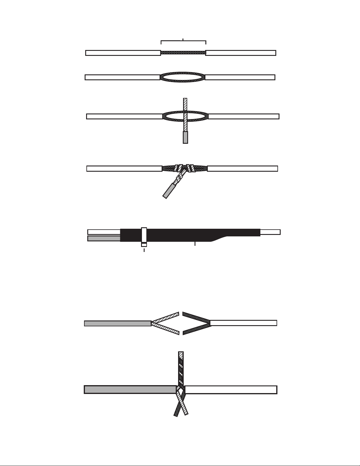
2. Strip back one inch of insulation on the wire you need to connect to.
One Inch of Bare Wire
3. Separate the vehicle wire as shown. Make the separation large enough to fit the other wire
through.
4. Insert the wire from the unit through the hole as shown.
5. Wrap the wire around one side then the other and finally around itself as shown.
1
2
3
6. Use electrical tape to wrap. Be sure to cover the wire about two inches on either side of the
connection. First pull the wire that you have just connected along side the wire you connected
to, tape and wire tie them together. Use this method for all connections.
Wire Tie
Electrical Tape
CA UTION: All wires must be wrapped and taped.
MAKING END TO END CONNECTIONS
FOLLOW THESE INSTR UCTIONS
1. When tying two separate wires together at their ends, strip back 1” of insulation on both
wires and separate the strands of wire as shown below.
2. T wist upper wires together, twist lower wires together as shown.
4
2
Page 4
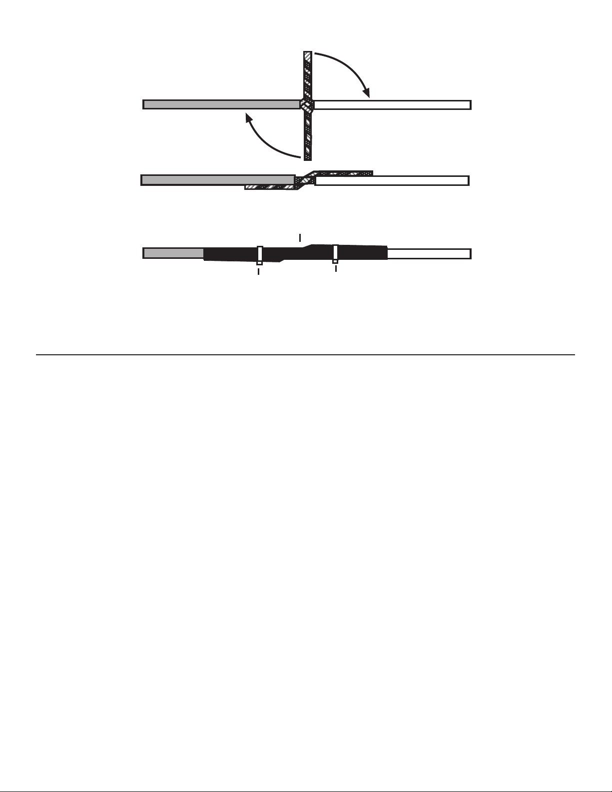
3. Lay upper twisted pair of wires over right wire as shown. Bring lower twisted pair of wires
up to meet the left wire as shown.
4. Use electrical tape to wrap, be sure to cover about 2 inches on either side of connection.
Secure with wire ties as shown.
Electrical Tape
Wire Tie
Wire Tie
Use this method ONLY when connecting two separate wires end to end.
INSTALLATION INSTRUCTIONS
Connecting to Power and Ground
1. T ouch the negative lead from a computer-friendly test light to a metal part of your vehicle and use
the positive lead to probe for a point in the fuse block that has 12 volts when your vehicle ignition
is off.
2. Remove the fuse at that position and touch the lead to both fuse contacts. Only one contact should
indicate 12 volts. Connect the system’s RED wire to that contact or any other constant 12 volt source,
then replace the fuse.
3. Connect the system’s BLACK wire to a metal vehicle chassis part, using an existing bolt or screw.
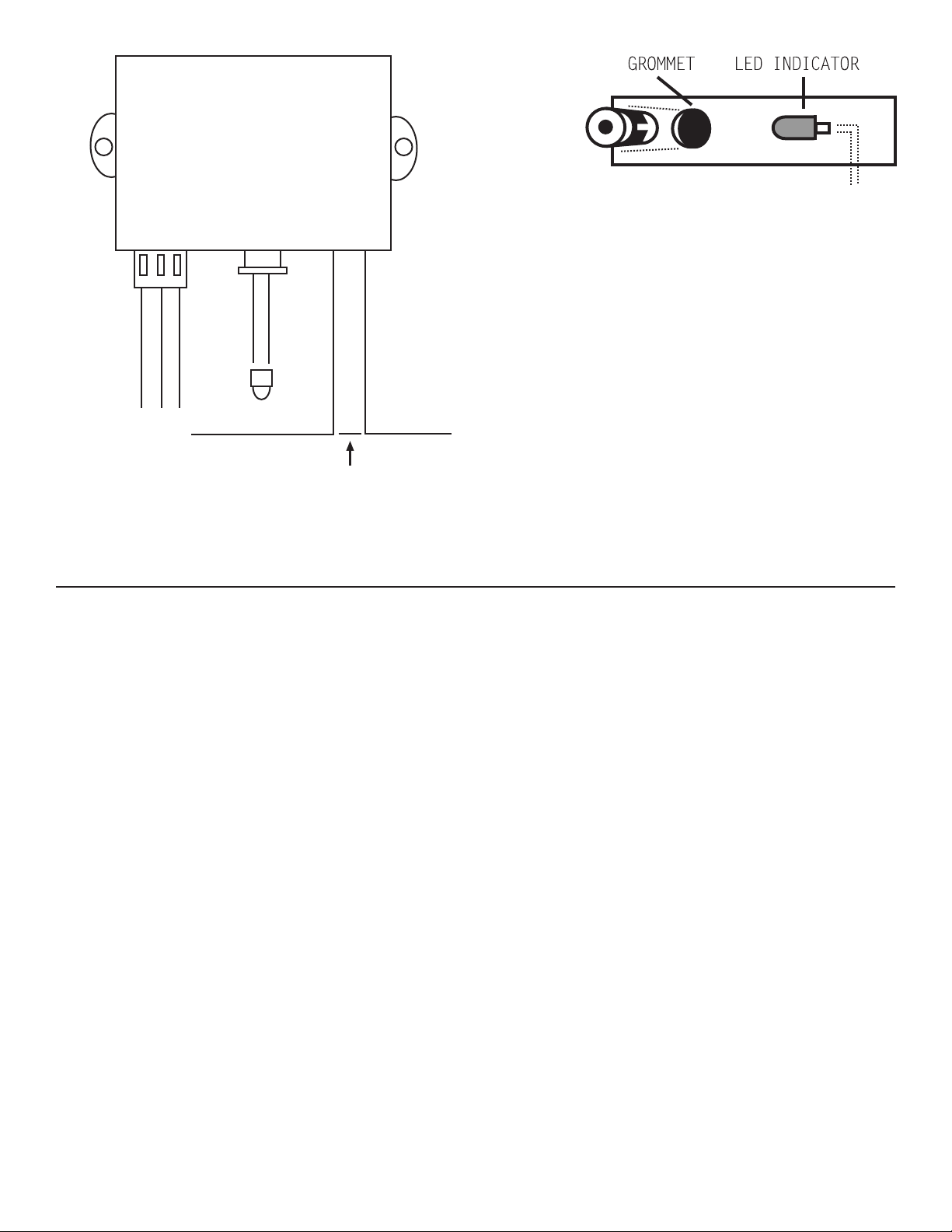
4. Plug the wiring harness three pin connector into the system with the YELLOW wire to the left as shown
below.
5. Immediately press Button #2 on your transmitter. This teaches the system to recognize the transmitter.
Connecting the Starter Immobilizer
Test for the cranking wire at the base of the steering column. When testing, the cranking wire will show
12 DC only when the key is in the cranking position. Once located, cut the wire in two. Try to crank the
engine, it should not crank. Next, mark both ends of the cranking wire. The wire running back into the
steering column should be marked KEY SIDE, and the wire running toward the engine should be marked STARTER
SIDE.
1. Connect the RED/BLACK wire from the wiring harness to the wire market KEY SIDE.
2. Connect the WHITE wire from the wiring harness to the wire marked STARTER SIDE. TEST: Press transmitter
Button #1 to arm the system and then try to start the engine, it should not start. Press transmitter
Button #2 to disarm the system. This time the engine should start. Make sure all your connections are
electrically sound.
Installing the Flashing LED Status Indicator
The LED indicator installs inside your vehicle and should be installed as high as possible and in view
from all windows. Drill a 1/4 mounting hole in the dash panel or use the supplied mounting bracket to
hold the LED status indicator in place. Push the LED through the hole, install the grommet from the front
side, then press the grommet and the LED back into the hole as shown below.
Connecting the LED Status Indicator
1. Plug the LED status indicator into the center connection of the control module as shown. TEST: Press
transmitter Button #1, the LED should flash.
3
Page 5
Control Module
Wiring
Harness
Red/Black to
Ignition Switch
Yellow - Antenna
Red - +12 Volts
Black - Ground
White to Starter
Status
Indicator
x
Cut the wire going from the ignition
switch to the starter solenoid.
OPERATING INSTRUCTIONS
Arming
Press transmitter Button #1 to arm the system. The LED indicator will flash, indicating that the system is
now armed.
Disarming
Press transmitter Button #2 to disarm the system. The LED indicator will shut off, indicating that the system
is disarmed.
4
 Loading...