

Page 1

NovaScale R440 E2
User's Guide
NOVASCALE
REFERENCE
86 A1 46FB 00
Page 2

Page 3

NOVASCALE
NovaScale R440 E2
User's Guide
Hardware
April 2009
BULL CEDOC
357 AVENUE PATTON
B.P.20845
49008 ANGERS CEDEX 01
FRANCE
REFERENCE
86 A1 46FB 00
Page 4
Droits de propriété et déni de responsabilité
Les informations contenues dans ce document, y compris les graphiques et les documents connexes, sont la propriété
de NEC Computers et/ou des tiers qui lui ont accordé des licences. NEC Computers et/ou lesdits tiers, selon le cas,
se réservent les brevets, copyrights et autres droits de propriété sur ce document, notamment les droits de conception,
de fabrication, de reproduction, d'utilisation et de commercialisation, sous réserve que d'autres n'en soient pas
bénéficiaires.
La conception et les spécifications des produits décrits dans ce document faisant l'objet d'améliorations constantes,
les informations contenues dans ce document peuvent être modifiées sans préavis. Aucune partie du présent
document ne peut être reproduite sans l'accord préalable écrit de NEC Computers.
Le ou les produits Bull décrits dans ce document sont couverts par l'accord de garantie qui les accompagne.
Cependant, leurs performances dépendent de facteurs tels que leur configuration, les données qu'ils hébergent et
leur utilisation. Leur mise en œuvre pouvant varier en fonction du client, l'adéquation de configurations et
d'applications spécifiques doit être déterminée par ledit client et ne relève pas de la responsabilité de Bull.
Marques commerciales
NEC ESMPRO, NEC DianaScope, NEC MWA, et ExpressBuilder sont des marques ou des marques déposées de
NEC Corporation.
NovaScale est une marque déposée de Bull SAS.
Adobe et Adobe Acrobat sont des marques déposées d'Adobe Systems, Incorporated.
Microsoft, Microsoft Windows, Windows NT, Windows 95, Windows 98, Windows 2000, Windows XP et
Windows Server 2003 sont des marques déposées de Microsoft Corporation.
Intel et Xeon sont des marques déposées d'Intel Corporation.
AMD est une marque déposée de Advanced Micro Devices, Inc.
Tous les autres noms de produit, de marque ou de société cités dans cette publication sont les marques commerciales
ou déposées de leurs détenteurs respectifs.
Copyright © NEC Computers SAS 2006
Vos suggestions sur la forme, le fond et la présentation de ce manuel sont les bienvenues.
Une feuille destinée à recevoir vos remarques se trouve à la fin du présent manuel.
Des corrections ou des modifications au contenu de ce document peuvent intervenir sans préavis. Bull SAS ne pourra pas
être tenu pour responsable des éventuelles erreurs qui pourraient y être contenues dans ce manuel, ni pour tout dommage
pouvant résulter de son application.
Page 5
Keep this User's Guide at hand for quick reference at anytime necessary.
SAFETY INDICATIONS
Follow the instructions in this User's Guide for your safety to use the server.
The server contains components with possible danger, hazards that may cause by ignoring warnings, and preve ntive actions
against such hazards.
Server components with possible danger are indicated with a warning label placed on or around them as well as described in
this User's Guide.
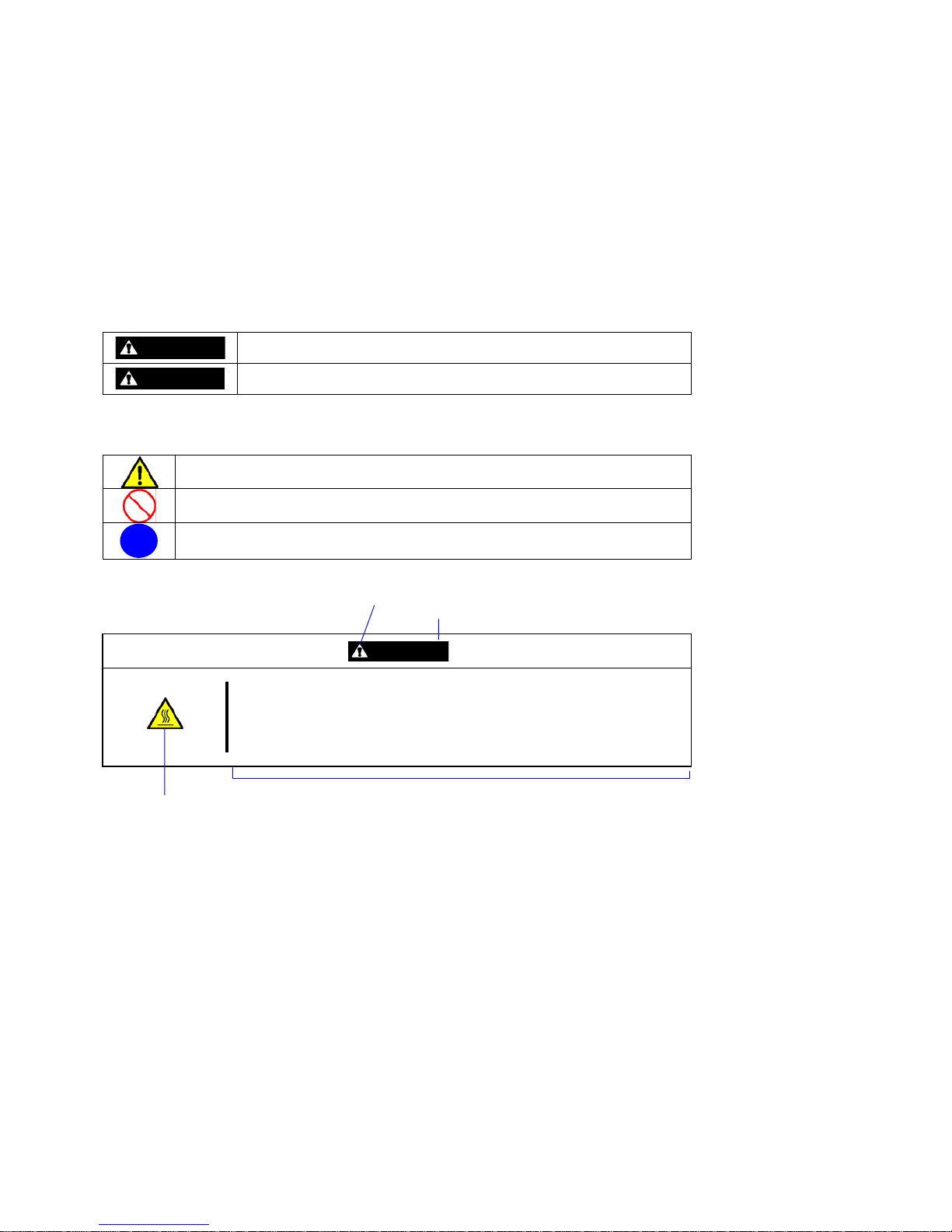
In the User's Guide or warning labels, "WARNING" or "CAUTION" is used to indicate a degree of danger. These terms are
defined as follows:
WARNING
Indicates the presence of a hazard that may result in death or serious
personal injury if the instruction is ignored.
CAUTION
Indicates the presence of a hazard that may cause minor personal injury,
including burns, or property damage if the instruction is ignored.
Precautions and notices against hazards are presented with one of the following three symbols. The individual symbols are
defined as follows:
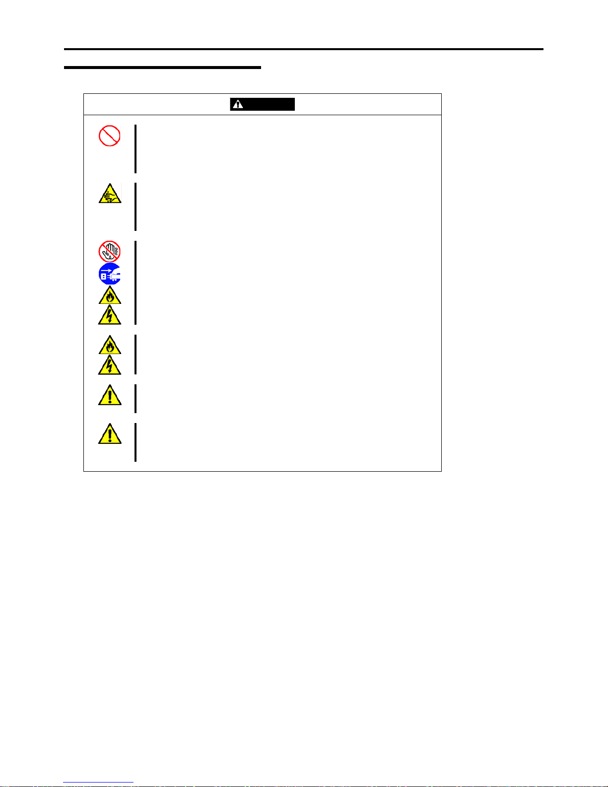
This symbol indicates the presence of a hazard if the instruction is ignored.
An image in the symbol illustrates the hazard type. (Attention)
This symbol indicates prohibited actions. An image in the symbol illustrates a
particular prohibited action. (Prohibited Action)
This symbol indicates mandatory actions. An image in the symbol illustrates a
mandatory action to avoid a particular hazard. (Mandatory Action)
(Example)
Symbol to draw attention
Term indicating a degree of danger
CAUTION
Hot surface
Immediately after the server is powered off, its internal components such as
hard disk drives are very hot. Leave the server until its internal components
fully cool down before installing/removing any component.
Symbol indicating a prohibited
action (may not always be
indicated)
Description of a danger
Page 6
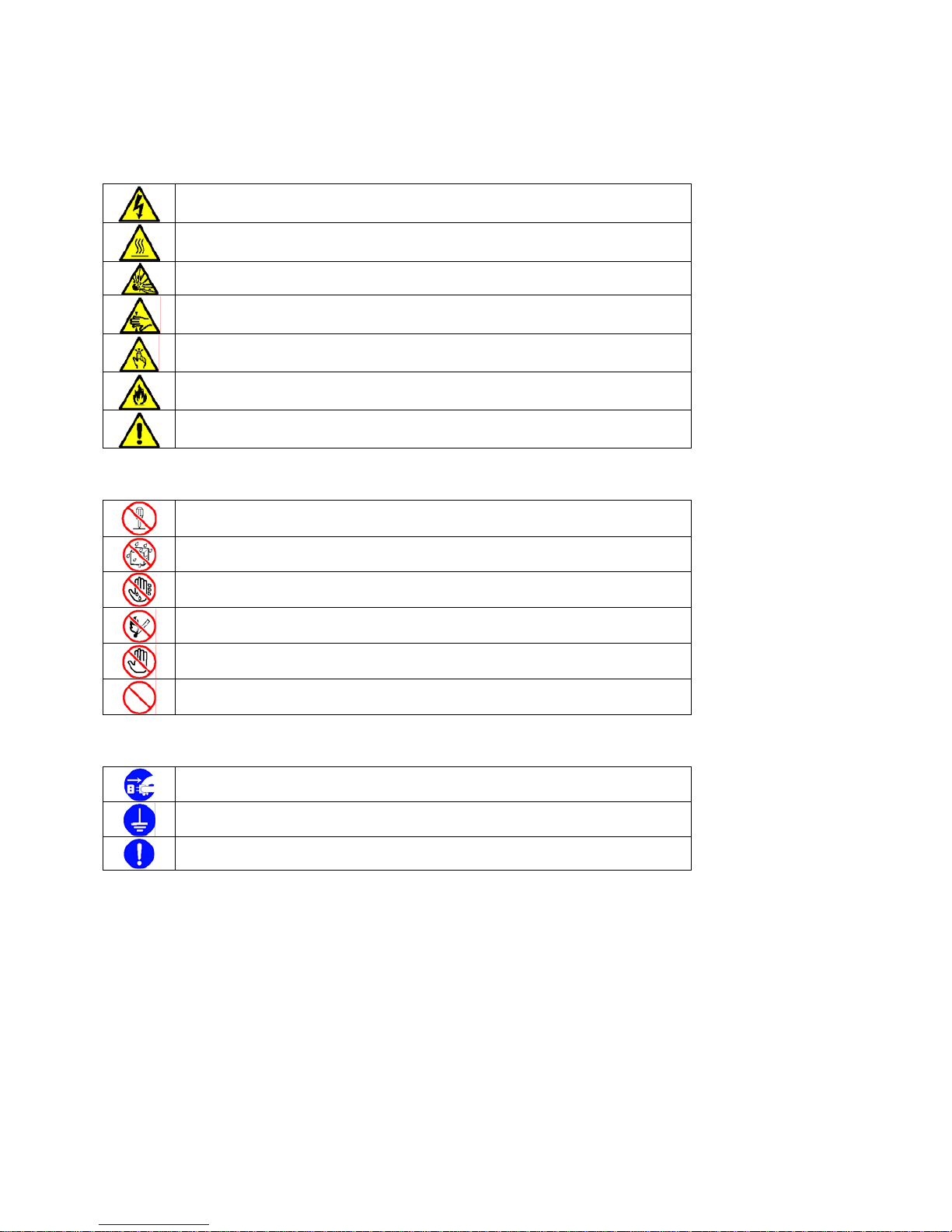
SYMBOLS USED IN THIS USER'S GUIDE AND WARNING LABELS
Attentions
Indicates that improper use may cause an electric shock.
Indicates that improper use may cause personal injury.
Indicates that improper use may cause explosion or burst.
Indicates that improper use may cause fingers to be caught.
Indicates that improper use may cause personal injury.
Indicates that improper use may cause fumes or fire.
Indicates a general notice or warning that cannot be specifically identified.
Prohibited Actions
Do not disassemble, repair, or modify the server. Otherwise, an electric shock or fire
may be caused.
Keep water or liquid away from the server. Otherwise, an electric shock or a fire may
be caused.
Do not touch the server components with wet hand. Otherwise, an electric shock may
be caused.
Do not place the server near a fire. Otherwise, a fire may be caused.
Do not touch any other component than specified. Otherwise, an electric shock or
burn may be caused.
Indicates a general prohibited action that cannot be specifically identified.
Mandatory Action
Unplug the power cord of the server. Otherwise, an electric shock or fire may be
caused.
Be sure to provide earthing. Otherwise, an electric shock or fire may be caused.
Indicates a mandatory action that cannot be specifically identified. Make sure to follow
the instruction.
Page 7
NOTE: This equipment has been tested and found to comply with the limits for a Class A digital device, pursuant to Part 15
of the FCC Rules. These limits are designed to provide reasonable protection against harmful interference when the equipment
is operated in a commercial environment. This equipment generates, uses, and can radiate radio frequency energy and, if not
installed and used in accordance with the instruction manual, may cause harmful interference to radio communications.
Operation of this equipment in a residential area is likely to cause harmful interference in which case the user will be required
to correct the interference at his own expense.
CE Statement
Warning: This is a Class A product. In domestic environment this product may cause radio interference in which case the user
may be required to take adequate measures (EN55022).
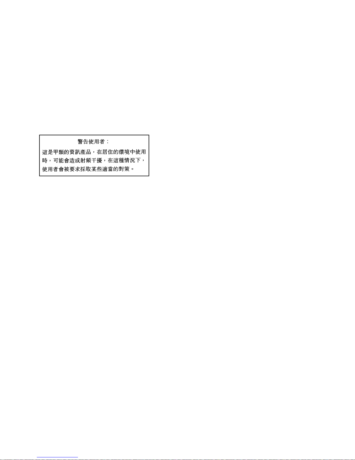
BSMI Statement
Notes:
(1) No part of this manual may be reproduced in any form without the prior written permission of Bull.
(2) The contents of this User's Guide may be revised without prior notice.
(3) The contents of this User's Guide shall not be copied or altered without the prior written permission of Bull.
(4) All efforts have been made to ensure the accuracy of all information in this User's Guide. If you notice any part unclear,
incorrect, or omitted in this User's Guide, contact the sales agent where you purchased this product.
(5) Bull assumes no liability arising from the use of this product, nor any liability for incidental or consequential damages
arising from the use of this User's Guide regardless of Item (4).
(6) If you find any missing pages or pages out of order in this manual, please contact your dealer for a replacement.
Page 8

i
PREFACE
Welcome to the NovaScale R440 E2 server.
The NovaScale R440 E2 server holds powerful performance and employs the latest technology to implement a computer for
the next generation. With its potential capabilities, the server may be used as a workstation PC that configures a client-server
system and provides high-speed processing and superior reliability.
Read this User's Guide thoroughly to fully understand how to use the server and appreciate its functions to the maximum
extent.
Page 9

ii
ABOUT THIS USER'S GUIDE
This User's Guide is a guide for proper setup and use of the server.
This User's Guide also covers useful procedures for dealing with difficulties and problems that may arise during setup or
operation of the server.
Keep this manual for future use.
The following describes how to proceed with this User's Guide.
How to Use This User's Guide
To aid you in finding information quickly, this User's Guide contains the following information:
Chapter 1 Notes on Using Your Server
includes information that needs attention to use the server. Make sure to read this chapter
before setting up and using the server. It also includes requirements and advisory information
for transfer and disposal of the server.
Chapter 2 General Description
includes information necessary to use the server, such as names and functions of its
components, handling of the optical disk drive.
Chapter 3 Setting Up Your Server
tells you how to select a site, unpack the system, assemble the rack-mount subsystem, make
cable connections, and power on your system.
Chapter 4 Configuring Your Server
tells you how to configure the system and provides instructions for running the BIOS SETUP
Utility and the RAID Configuration utility, which is used to configure RAID System in your
system. This chapter also provides information on mother board jumper settings.
Chapter 5 Installing the Operating System with Express Setup
describes how to install the operating system.
Chapter 6 Installing and Using Utilities
describes how to install the utilities for the server. It also includes a description on using the
attached "ExpressBuilder" DVD.
Chapter 7 Maintenance
provides you with all the information necessary to maintain successful operation of the server.
This chapter also includes a description on relocating and storing the server.
Chapter 8 Troubleshooting
contains helpful information for solving problems that might occur with your system.
Chapter 9 Upgrading Your Server
provides you with instructions for upgrading your system with an additional processor, optional
memory, optional add-in cards, hard disk drives, peripheral devices, and power supply.
Appendix A Specification
provides specifications for your server.
Appendix B Other Precautions
provides supplementary notes on using the server.
Page 10

iii
Appendix C IRQ and I/O Port Address
provides a list of factory-set IRQs and I/O port addresses assigned.
Appendix D Installing Windows Server 2008
describes how to install Microsoft Windows Server 2008 without using Express Setup. Using
the Express Setup tool is recommended for installing Windows Server 2008. See Chapter 5
for details.
Appendix E Installing Windows Server 2003 x64 Editions
describes how to install Microsoft Windows Server 2003 x64 Editions without using Express
Setup. Using the Express Setup tool is recommended for installing Windows Server 2003 x64
Editions. See Chapter 5 for details.
Appendix F Installing Windows Server 2003
describes how to install Microsoft Windows Server 2003 without using Express Setup. Using
the Express Setup tool is recommended for installing Windows Server 2003. See Chapter 5
for details.
Appendix G Using a Client Computer Which Has a CD Drive
describes how to install the management software of ExpressBuilder to the client computer
without the DVD drive.
Appendix H Product Configuration Record Table
provides a table to be filled with your server configuration.
Text Conventions
The following conventions are used throughout this User's Guide. For safety symbols, see "SAFETY INDICATIONS"
provided earlier.
IMPORTANT:
Items that are mandatory or require attention when using the server
NOTE:
Helpful and convenient piece of information
IN THE PACKAGE
The carton contains various accessories, as well as the server itself. If you find any component missing or damaged, contact
your service representative.
Page 11
iv
CONTENTS
Preface ..............................................................................................................................................i
About This User's Guide..................................................................................................................ii
In the Package................................................................................................................................ iii
Chapter 1 ...........................................................................................................................1-1
Notes on Using Your Server ............................................................................................1-1
Warning Labels ............................................................................................................................ 1-2
Safety Notes................................................................................................................................. 1-3
General .................................................................................................................................... 1-3
Power Supply and Power Cord Use......................................................................................... 1-4
Rack......................................................................................................................................... 1-5
Installation, Relocation, Storage, and Connection................................................................... 1-6
Cleaning and Working with Internal Devices.......................................................................... 1-8
During Operation..................................................................................................................... 1-9
For Proper Operation ................................................................................................................. 1-10
Transfer to Third Party............................................................................................................... 1-12
Disposal and Consumables ........................................................................................................1-13
User Support .............................................................................................................................. 1-14
Chapter 2 ...........................................................................................................................2-1
General Description..........................................................................................................2-1
Overview...................................................................................................................................... 2-2
External View .......................................................................................................................... 2-3
Front View with Front Bezel Closed ....................................................................................... 2-4
Front View with Front Bezel Removed................................................................................... 2-5
Rear View ................................................................................................................................ 2-6
Internal View ........................................................................................................................... 2-8
Mother Board ........................................................................................................................ 2-10
Status Indicators..........................................................................................................................2-11
POWER LED ( ) ...............................................................................................................2-11
STATUS LED ( )...............................................................................................................2-11
DISK ACCESS LED ( )...................................................................................................... 2-13
ACT LED ( ) ................................................................................................................... 2-13
UID LED (UID) .................................................................................................................... 2-13
Disk Access LED................................................................................................................... 2-13
Hard Disk Drive LED............................................................................................................ 2-14
LAN Connector LEDs........................................................................................................... 2-16
AC POWER LED.................................................................................................................. 2-17
Standard Features....................................................................................................................... 2-18
Remote Management Feature................................................................................................ 2-19
Degradation Feature .............................................................................................................. 2-20
Memory RAS Features.......................................................................................................... 2-20
Remote Power-On Feature (Wake On LAN) ......................................................................... 2-20
AC-Link Feature.................................................................................................................... 2-20
System Security..................................................................................................................... 2-21
Notes on Using Power Control Feature................................................................................. 2-22
ExpressBuilder........................................................................................................................... 2-24
NEC ESMPRO .......................................................................................................................... 2-25
Maintenance Tools ..................................................................................................................... 2-25
System Diagnostic Utility .......................................................................................................... 2-25
Using Your Server...................................................................................................................... 2-26
Front Bezel ............................................................................................................................ 2-26
POWER Switch..................................................................................................................... 2-28
Page 12

v
Identification of Servers ~ UID Switch ~.............................................................................. 2-33
Optical Disk Drive................................................................................................................. 2-34
Chapter 3 ...........................................................................................................................3-1
Setting Up Your Server.....................................................................................................3-1
Setup Flow ................................................................................................................................... 3-2
Selecting Server Site.................................................................................................................... 3-3
Installing the Server ..................................................................................................................... 3-5
Installation ............................................................................................................................... 3-6
Removal................................................................................................................................. 3-14
Connecting Peripheral Devices.................................................................................................. 3-18
Connecting the Power Cord.......................................................................................................3-20
Turning On the Server................................................................................................................ 3-22
Installing the Operating System.................................................................................................3-23
Installing Utilities ...................................................................................................................... 3-23
Making Backup Copies of System Information......................................................................... 3-23
Chapter 4 ...........................................................................................................................4-1
Configuring Y our Server..................................................................................................4-1
System BIOS (SETUP)................................................................................................................ 4-1
Starting SETUP Utility............................................................................................................ 4-2
Description on On-Screen Items and Key Usage .................................................................... 4-3
Menu and Parameter Descriptions........................................................................................... 4-4
RAID System Configuration...................................................................................................... 4-23
RAID ..................................................................................................................................... 4-23
Configuration by Onboard RAID Controller (3.5-inch Disk Model) .................................... 4-29
LSI Software RAID Configuration Utility and Universal RAID Utility ............................... 4-43
Configuration by Internal RAID Controller (2.5-inch Disk Model)...................................... 4-46
Before Using WebBIOS ........................................................................................................ 4-51
Using WebBIOS .................................................................................................................... 4-54
Configuring a Virtual Drive................................................................................................... 4-69
Operating Various Features.................................................................................................... 4-85
Locate .................................................................................................................................... 4-96
Slow Initialize........................................................................................................................ 4-97
WebBIOS and the Universal RAID Utility............................................................................ 4-98
Configuring Mother Board Jumpers ........................................................................................ 4-102
Chapter 5 ...........................................................................................................................5-1
Installing the Operating System with Express Setup ...................................................5-1
About Express Setup.................................................................................................................... 5-2
Windows Server 2008.................................................................................................................. 5-3
Notes on Windows Installation................................................................................................ 5-3
Flow of Setup .......................................................................................................................... 5-7
Installing Windows Server 2008.............................................................................................. 5-8
Installing and Setting Device Drivers.................................................................................... 5-22
Windows Server 2003................................................................................................................ 5-32
Notes on Windows Installation.............................................................................................. 5-32
Flow of Setup ........................................................................................................................ 5-38
Installing Windows Server 2003............................................................................................ 5-39
Installing and Setting Device Drivers.................................................................................... 5-48
Setting for Solving Problems..................................................................................................... 5-58
Memory Dump (Debug Information) - Windows Server 2008 - ........................................... 5-58
Memory Dump (Debug Information) - Windows Server 2003 - ........................................... 5-61
How to Create a User-mode Process Dump File ................................................................... 5-64
Network Monitor................................................................................................................... 5-66
Re-installing the Operation System if Multiple Logical Drives Exist ................................... 5-68
Installing Maintenance Utilities ................................................................................................. 5-70
Page 13

vi
Updating the System.................................................................................................................. 5-70
Making Backup Copies of System Information......................................................................... 5-71
Installing with the OEM-Disk for Mass Storage Device....................................................... 5-72
Chapter 6 ...........................................................................................................................6-1
Installing and Using Utilities............................................................................................6-1
ExpressBuilder............................................................................................................................. 6-2
Autorun Menu ......................................................................................................................... 6-6
Parameter File Creator ................................................................................................................. 6-7
Parameter File.......................................................................................................................... 6-8
NEC ESMPRO .......................................................................................................................... 6-20
Functions and Features ..........................................................................................................6-20
Universal RAID Utility.............................................................................................................. 6-21
Setup with Express Setup ...................................................................................................... 6-21
Manual Setup......................................................................................................................... 6-22
Using the Universal RAID Utility via the Network............................................................... 6-23
Easy Configuration................................................................................................................ 6-23
Creating Logical Drive of RAID 6........................................................................................ 6-23
Bull Product Info Collection Utility .......................................................................................... 6-24
Installation ............................................................................................................................. 6-24
Using the Utility .................................................................................................................... 6-24
Uninstallation ........................................................................................................................ 6-24
Chapter 7 ...........................................................................................................................7-1
Maintenance......................................................................................................................7-1
Making Backup Copies................................................................................................................ 7-1
Cleaning....................................................................................................................................... 7-2
Cleaning the Server ................................................................................................................. 7-3
Cleaning the Interior................................................................................................................ 7-4
Cleaning the Keyboard/Mouse ................................................................................................ 7-5
Cleaning Disc .......................................................................................................................... 7-6
System Diagnostics...................................................................................................................... 7-7
Test Items ................................................................................................................................ 7-7
Startup and Exit of System Diagnostics .................................................................................. 7-8
Relocating/Storing The Server....................................................................................................7-11
Chapter 8 ...........................................................................................................................8-1
Troubleshooting................................................................................................................8-1
System Viewers............................................................................................................................ 8-2
LEDs............................................................................................................................................ 8-2
Error Messages ............................................................................................................................ 8-3
Error Messages after Power-on ............................................................................................... 8-3
POST Error Messages .............................................................................................................8-4
Messages displayed by RAID Controller during POST .......................................................... 8-8
Beep Codes.............................................................................................................................8-11
Error Messages on Virtual LCD ............................................................................................ 8-12
Solving Problems....................................................................................................................... 8-15
Problems with the Server....................................................................................................... 8-15
Problems with RAID System and RAID Controller.............................................................. 8-22
Problems with Windows........................................................................................................ 8-26
Problems with the FibreChannel Controller (Emulex LPe1150 or LPe11002)...................... 8-32
Problems with ExpressBuilder .............................................................................................. 8-33
Problems with Express Setup ................................................................................................ 8-34
Problems with Parameter File Creator................................................................................... 8-35
Problems with the Autorun Menu.......................................................................................... 8-36
Collecting Dr. Watson Diagnostic Information.......................................................................... 8-37
Memory Dump........................................................................................................................... 8-37
Page 14

vii
Preparing for Memory Dumping ........................................................................................... 8-37
Saving the Dump File............................................................................................................8-38
Recovery for WINDOWS System ............................................................................................. 8-39
Maintenance Tools ..................................................................................................................... 8-40
Starting the Maintenance Tools ............................................................................................. 8-40
Function of Maintenance Tools ............................................................................................. 8-42
Maintenance Tools with Remote Console ............................................................................. 8-44
Resetting the Server ................................................................................................................... 8-46
Forced Shutdown ....................................................................................................................... 8-46
Chapter 9 ...........................................................................................................................9-1
Upgrading Y our Server.....................................................................................................9-1
Safety Notes................................................................................................................................. 9-2
Anti-static Measures .................................................................................................................... 9-3
Preparing for Installation and Removal ....................................................................................... 9-4
Hard Disk Drive........................................................................................................................... 9-6
3.5-inch Disk Model................................................................................................................ 9-6
2.5-inch Disk Model................................................................................................................ 9-8
Installation ............................................................................................................................... 9-9
Removal................................................................................................................................. 9-15
Notes on Replacing Hard Disk Drives in the RAID System ................................................. 9-18
Power Supply Unit..................................................................................................................... 9-19
Installation ............................................................................................................................. 9-19
Replacing a Failing Power Supply Unit ................................................................................ 9-22
Top Cover .................................................................................................................................. 9-23
Removal................................................................................................................................. 9-23
Installation ............................................................................................................................. 9-23
DIMM ........................................................................................................................................ 9-24
Installation Order................................................................................................................... 9-25
Memory Clock....................................................................................................................... 9-27
Memory RAS Feature............................................................................................................ 9-27
Installation ............................................................................................................................. 9-28
Removal................................................................................................................................. 9-30
Using the Memory RAS Features.......................................................................................... 9-31
Processor (CPU) ........................................................................................................................ 9-38
Installation ............................................................................................................................. 9-39
Removal................................................................................................................................. 9-45
PCI Board .................................................................................................................................. 9-46
Notes...................................................................................................................................... 9-48
Installation ............................................................................................................................. 9-49
Removal................................................................................................................................. 9-52
Installing RAID Controller.................................................................................................... 9-52
Removing RAID Controller .................................................................................................. 9-55
Installing an Additional Battery for the RAID Controller ..................................................... 9-56
Use of Internal Hard Disk Drives in the RAID System............................................................. 9-76
3.5-inch Disk Model.............................................................................................................. 9-77
2.5-inch Disk Model.............................................................................................................. 9-79
Floppy Disk Drive ..................................................................................................................... 9-81
Optical Disk Drive ..................................................................................................................... 9-85
Replacement Procedure ......................................................................................................... 9-86
Appendix A....................................................................................................................... A-1
Specifications................................................................................................................... A-1
Appendix B....................................................................................................................... B-1
Other Precautions............................................................................................................ B-1
Transfer Rate of the On-board LAN controller .......................................................................B-1
Page 15

viii
Server Management Software .................................................................................................B-1
Floppy Disk .............................................................................................................................B-1
CD/DVD Discs........................................................................................................................ B-3
Tape Media .............................................................................................................................. B-3
Keyboard .................................................................................................................................B-3
Mouse ......................................................................................................................................B-5
Appendix C....................................................................................................................... C-1
IRQ..................................................................................................................................... C-1
Appendix D....................................................................................................................... D-1
Installing Windows Server 2008..................................................................................... D-1
Notice...........................................................................................................................................D-1
Optional Board Supported by ExpressBuilder.........................................................................D-1
Service Pack Which ExpressBuilder Supports ........................................................................D-1
Installing Service Pack ............................................................................................................D-1
Updating System .....................................................................................................................D-2
Installing on the Mirrored Volume...........................................................................................D-2
Mounting MO Device..............................................................................................................D-2
About Removable Media.........................................................................................................D-2
Floppy Disk Drive ...................................................................................................................D-2
About the System Partition Size..............................................................................................D-2
Installing Windows Server 2008..................................................................................................D-4
Preparations for Installation.....................................................................................................D-4
Creating "Windows Server 2008 OEM-Disk for ExpressBuilder"..........................................D-4
Windows Server 2008 Clean Installation ................................................................................D-6
Updating the System..............................................................................................................D-20
Driver Installation and Advanced Settings.................................................................................D-23
LAN Driver and PROSet.......................................................................................................D-23
Network Driver......................................................................................................................D-25
Optional Network Board Driver............................................................................................D-25
Adapter Fault Tolerance (AFT)/Adaptive Load Balancing (ALB)........................................D-25
Setting WOL..........................................................................................................................D-27
Graphics Accelerator Driver ..................................................................................................D-28
Installing SCSI Controller Driver..........................................................................................D-28
Installing SAS Controller Driver...........................................................................................D-28
Installing RAID Controller Driver.........................................................................................D-29
Installing Fibre Channel Controller Driver............................................................................D-29
About Windows Activation ...................................................................................................D-30
Procedure to Set PAE Option.................................................................................................D-34
Setting for Solving Problems.....................................................................................................D-35
Appendix E........................................................................................................................E-1
Installing Windows Server 2003 x64 Editions................................................................E-1
Notice........................................................................................................................................... E-1
Optional Board Supported by ExpressBuilder.........................................................................E-1
Service Pack Which EXPRESSBUILDER Supports ..............................................................E-2
Installing Service Pack ............................................................................................................ E-2
Updating System .....................................................................................................................E-2
Re-installing to the Hard Disk Drive which has been upgraded to Dynamic Disk.................. E-2
Mounting MO Device..............................................................................................................E-2
About Removable Media......................................................................................................... E-2
Floppy Disk Drive ................................................................................................................... E-2
About the System Partition Size.............................................................................................. E-3
Installing Windows Server 2003 x64 Editions............................................................................. E-4
Creating "Windows Server 2003 x64 Edition OEM-Disk for EXPRESSBUILDER".......... E-5
Windows Server 2003 x64 Editions Clean Installation ...........................................................E-7
Page 16

ix
Updating the System - Applying Service Pack -....................................................................E-10
Driver Installation and Advanced Settings................................................................................. E-15
PROSet .................................................................................................................................. E-15
Network Driver...................................................................................................................... E-16
Optional Network Board Driver............................................................................................ E-17
Adapter Fault Tolerance (AFT)/Adaptive Load Balancing (ALB)........................................ E-17
Setting WOL.......................................................................................................................... E-19
Graphics Accelerator Driver.................................................................................................. E-21
Installing SCSI Controller Driver.......................................................................................... E-21
Installing SCSI Controller Driver.......................................................................................... E-21
Installing SAS Controller Driver........................................................................................... E-21
Installing RAID Controller Driver.........................................................................................E-22
About Windows Activation ...................................................................................................E-23
Setting for Solving Problems..................................................................................................... E-24
Appendix F ........................................................................................................................F-1
Installing Windows Server 2003......................................................................................F-1
BEFORE INSTALLING WINDOWS SERVER 2003 ................................................................ F-1
Optional Board Supported by ExpressBuilder......................................................................... F-1
Service Pack Which EXPRESSBUILDER Supports ..............................................................F-2
Application of Service Pack .................................................................................................... F-2
Updating System ..................................................................................................................... F-2
Re-installing to the Hard Disk which has been upgraded to Dynamic Disk............................ F-2
Mounting MO Device..............................................................................................................F-2
About Removable Media......................................................................................................... F-2
Floppy Disk Drive ................................................................................................................... F-2
About the Upgrade to Windows Server 2003 R2..................................................................... F-2
About the System Partition Size.............................................................................................. F-4
Installing Windows Server 2003..................................................................................................F-5
Creating "Windows Server 2003 OEM-Disk for EXPRESSBUILDER"..................................... F-6
Windows Server 2003 Clean Installation ................................................................................F-8
Procedure for License Authentication ................................................................................... F-11
Updating the System - Applying Service Pack -.................................................................... F-11
Driver Installation and Advanced Settings................................................................................. F-16
PROSet .................................................................................................................................. F-16
Network Driver...................................................................................................................... F-17
Adapter Fault Tolerance (AFT)/Adaptive Load Balancing (ALB)........................................ F-17
Setting WOL.......................................................................................................................... F-17
Graphics Accelerator Driver.................................................................................................. F-20
Installing SCSI Controller Driver.......................................................................................... F-20
Installing SAS Controller Driver........................................................................................... F-20
Installing RAID Controller Driver......................................................................................... F-21
About Windows Activation ................................................................................................... F-22
Procedure to Set PAE Option................................................................................................. F-24
Setting for Solving Problems..................................................................................................... F-24
Appendix G....................................................................................................................... G-1
Using a Client Computer Which Has a CD Drive.......................................................... G-1
Appendix H....................................................................................................................... H-1
Product Configuration Record Table............................................................................. H-1
Hardware .................................................................................................................................H-1
Software...................................................................................................................................H-3
Page 17

Chapter 1
Notes on Using Your Server
This chapter includes information necessary for proper and safe operation of the server.
Page 18
1-2 Notes on Using Your Server
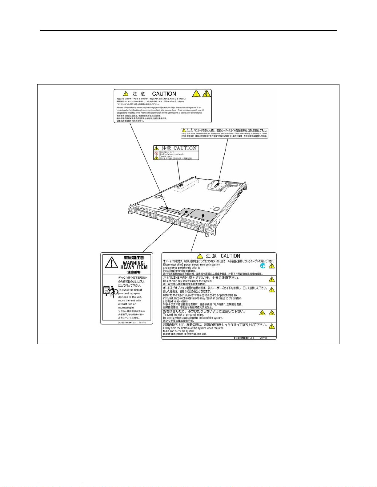
WARNING LABELS
The warning label is attached to components with possible danger or their vicinity in your server to inform the user that a
hazardous situation may arise when operating the server. (Do not intentionally remove or damage any of the labels.)
If you find any labels totally/partially removed or illegible due to damage, contact your sales representative.
Page 19
Notes on Using Your Server 1-3
SAFETY NOTES
This section provides notes on using the server safely. Read this section carefully to ensure proper and safe use of the server.
For symbols, see "SAFETY INDICATIONS" provided earlier.
For part names described in the safety instruction chapter in this guide, see Chapter 2.
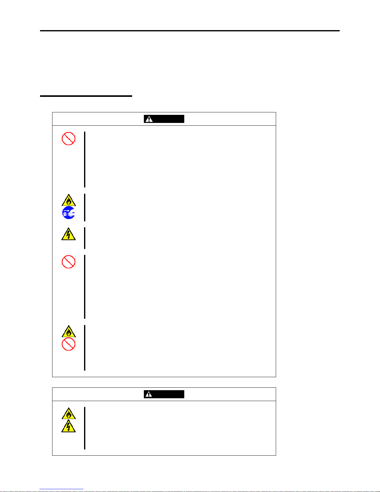
General
WARNING
Do not use the server for services where critical high availability may directly
affect human lives.
Your server is not intended to be used with or control facilities or devices
concerning human lives, including medical devices, nuclear facilities and
devices, aeronautics and space devices, transportation facilities and devices;
and facilities and devices requiring high reliability. Bull assumes no liability for
any accident resulting in personal injury, death, or property damage if the
server has been used in the above conditions.
Do not use the server if any smoke, odor, or noise is present.
If smoke, odor, or noise is present, immediately turn off the server and
disconnect the power plug from the outlet, then contact your service
representative. Using the server in such conditions may cause a fire.
Keep needles or metal objects away from the server.
Do not insert needles or metal objects into ventilation holes in the server or
openings in the optical disk drive. Doing so may cause an electric shock.
Do not use the server in any unapproved place.
Install the server on a standard EIA 19-inch rack assembly. Do not install the
rack containing the server in a place inappropriate to the rack installation
environment.
Failure to follow these instructions may cause some bad influences to be
imposed on the server and other systems installed on the rack and also a fire or
personal injury due to falling of the rack may occur. For the detailed explanation
on the place where the server should be installed and the earthquake-resistant
construction for the rack, refer to the manual attached to the rack or contact you
service representative.
Always install the server on a rack conforming to the relevant standard.
Install the server on a rack confirming to the EIA standard for the Server to be
used. Do not use the server with installed on any other rack than standard EIA
19-inch rack or without the installation on a proper rack. Failure to follow these
instructions may cause the server to operate incorrectly and/or personal injury
or damages of surrounding devices to occur. Contact your service
representative for the racks available for the server.
CAUTION
Keep water or foreign matter away from the server.
Do not let any form of liquid (water etc.) or foreign matter (e.g., pins or paper
clips) enter the server. Failure to follow this warning may cause an electric
shock, a fire, or a failure of the server. When such things accidentally enter the
server, immediately turn off the power and disconnect the power plug from the
outlet. Do not disassemble the server. Contact your service representative.
Page 20
1-4 Notes on Using Your Server
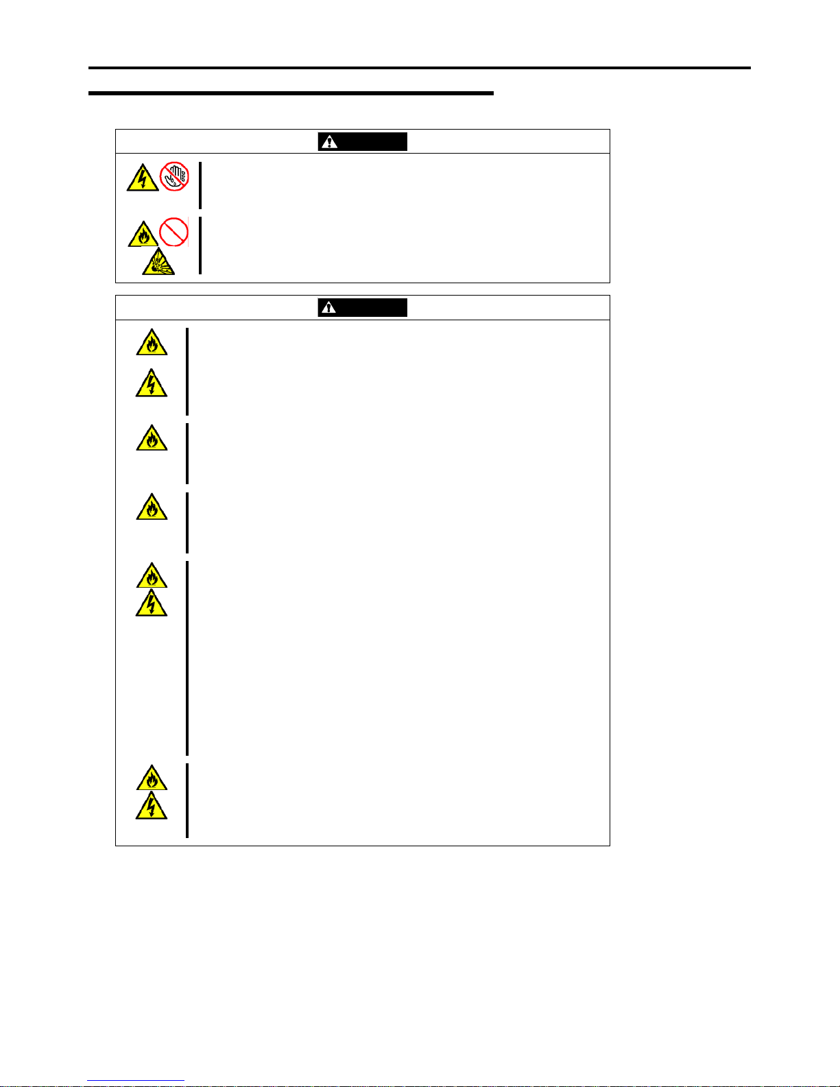
Power Supply and Power Cord Use
WARNING
Do not hold the power plug with a wet hand.
Do not disconnect/connect the plug while your hands are wet. Failure to
ollow this warning may cause an electric shock.
f
Do not connect the ground wire to a gas pipe.
Never connect the ground wire to a gas pipe. Failure to follow this warning
may cause a gas explosion.
CAUTION
Plug in to a proper power source.
Use a proper wall outlet. Use of an improper power source may cause a fire or
a power leak.
Do not install the server where you need an extension cord. Use of a cord that
does not meet the power specifications of the server may heat up the cord and
ause a fire.
c
Do not connect the power cord to an outlet that has an illegal number of
connections.
The electric current exceeding the rated flow overheats the outlet, which may
cause a fire.
Insert the power plug into the outlet as far as it goes.
Heat generation resulting from a halfway inserted power plug (imperfect
contact) may cause a fire. Heat will also be generated if condensation is formed
on dusty blades of the halfway inserted plug, increasing the possibility of fire.
Use the authorized power cord only.
Use only the power cord that comes with your server. Use of an unauthorized
power cord may cause a fire when the electric current exceeds the rated flow.
Also, observe the following to prevent an electric shock or fire caused by a
damaged cord.
Do not stretch the cord harness. Do not alter, modify, or repair the
power cord.
Do not pinch the power cord.
Do not bend the power cord. Do not secure the power cord with
staples or equivalents.
Keep chemicals away from the
power cord.
Do not use any damaged power
cord. (Replace a damaged power
cord with a new one of the same
specifications. Ask your service
representative for replacement.)
Do not twist the power cord.
Do not place any object on the
power cord.
Do not bundle power cords.
Do not use the attached power cord for any other devices or usage.
The power cord that comes with your server is designed aiming to connect with
this server and to use with the server, and its safety has been tested. Do not
use the attached power cord for any other purpose. Doing so may cause a fire
or an electric shock.
Page 21
Notes on Using Your Server 1-5
Rack
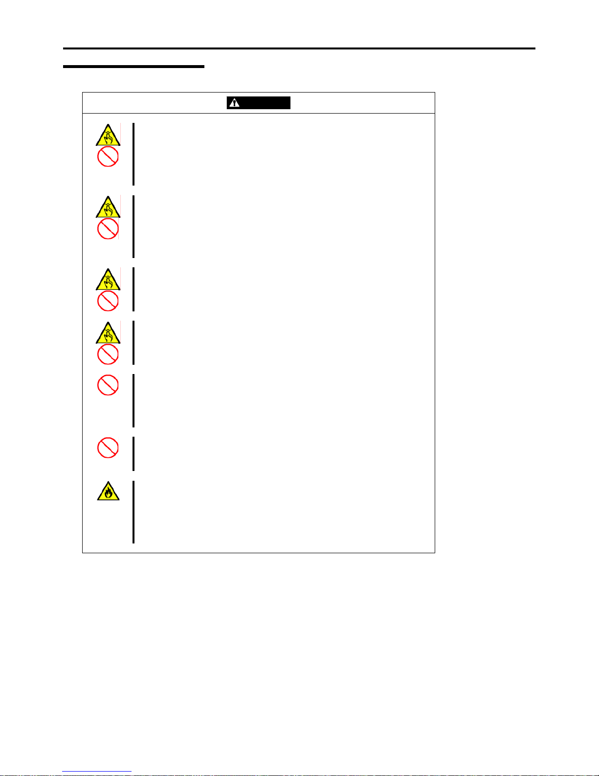
CAUTION
Do not carry or install the server only by a single person.
More than one person is required to carry or install the rack. Failure to follow
this instruction may cause the rack to fall to result in personal injury and/or
breakages of surrounding devices. In particular, a high rack (such as 44U rack)
is unstable if it is not fixed by stabilizers. More than one person must always
carry or install the rack while they support it.
Do not install the server so that the load may be concentrated on a specific
point.
Install stabilizers on the rack so that the total load of the rack and devices
mounted on the rack is not concentrated on a singe point or join more than one
rack with each other to distribute the load. Failure to follow this instruction may
cause the rack to fall to result in personal injury.
Do not install components on the server only by a single person.
More than one person is required to install parts including the doors and trays
for the rack. Failure to follow this instruction may cause some parts to fall to be
broken and/or to result in personal injury.
Insert hinges completely.
When installing the rack door, make sure that hinge pins at top and bottom of
the door are completely inserted into the rack. Failure to follow this instruction
may cause the door to fall to be broken and/or to result in personal injury.
Anchor the equipment rack.
The equipment rack must be anchored to an unmovable support to prevent it
from falling over when one or more servers are extended in front of it on slide
assemblies. The anchors must be able to withstand a force of up to 113 kg (250
lbs.) You must also consider the weight of any other device installed in the rack.
Do not leave more than one device being pulled out from the rack.
Pulling out more than one device from the rack may cause the rack to be fallen.
Only pull out a single device from the rack at a time.
Do not provide the wiring for the server to exceed the rating of the power
supply.
To prevent burns, fires, and device damages, the power supplied to the power
supply in the rack shall not exceed the rating load of the power branch circuit.
Contact your electric constructor or the local power company for the
requirements on the wiring and installation of electric facilities.
Page 22
1-6 Notes on Using Your Server
Installation, Relocation, Storage, and Connection
WARNING
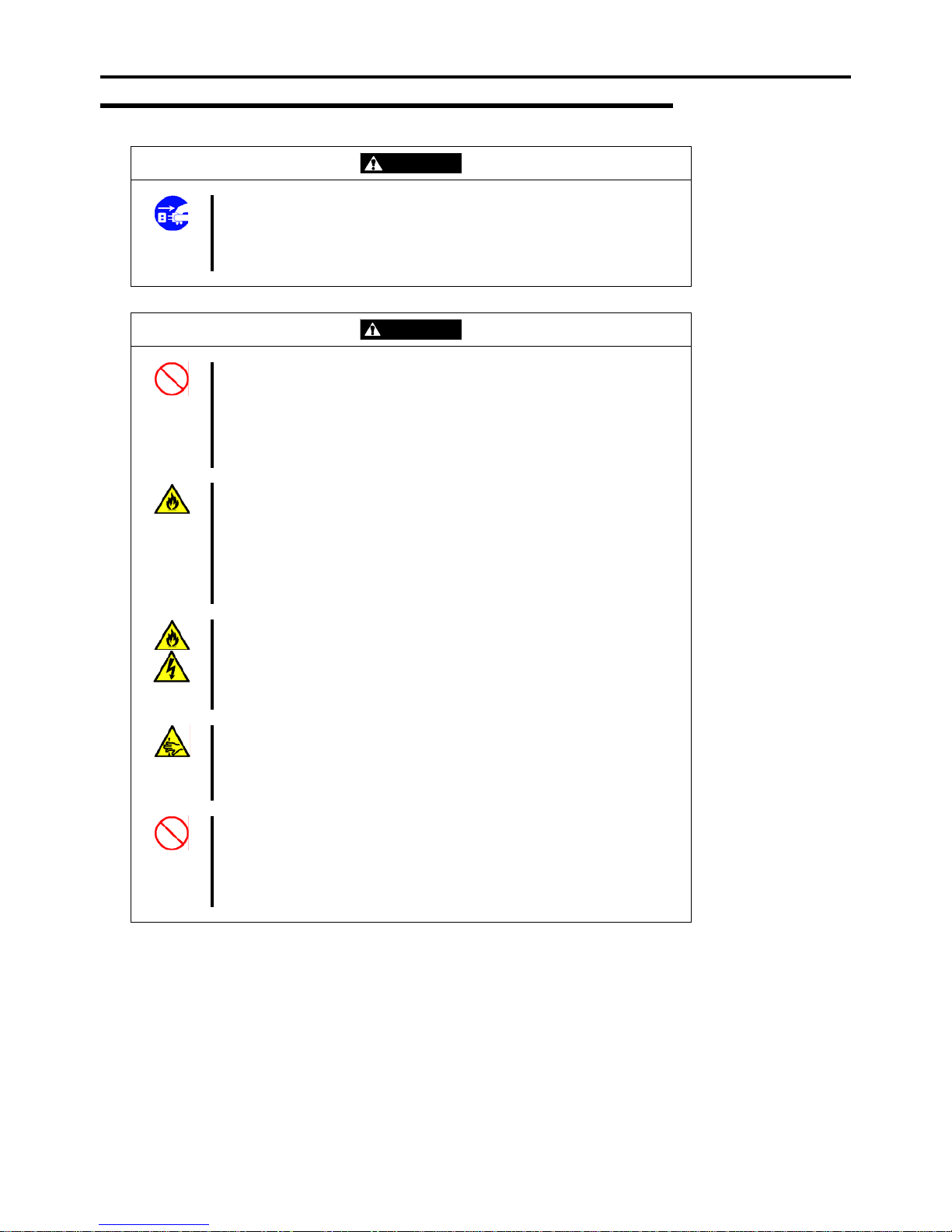
Disconnect the power cord(s) before installing or removing the server.
Make sure to power off the server and disconnect the power cord(s) from a
power outlet before installing/removing the server. All voltage is removed only
when the power cords are unplugged.
CAUTION
Never attempt to lift the server only by yourself.
The server weighs max. 21 kg (depending on its hardware configuration).
Carrying the server only by yourself may strain your back. Hold the server firmly
by its bottom with another person to carry it. Do not hold the front door to lift the
server. The front door may be disengaged from the server, causing personal
injury.
Do not install the server in any place other than specified.
Do not install the server in the following places or any place other than specified
in this User's Guide. Failure to follow this instruction may cause a fire.
a dusty place
a humid place such as near a boiler
a place exposed to direct sunlight
an unstable place
Do not install the server on a rack with leaving covers removed.
Do not install the server on a rack with the cover being removed. Failure to
follow this instruction may reduce the cooling effect in the server to result in
some malfunction and/or dusts to enter the server to result in a fire or electric
shock.
Do not pinch your finger with rails or other components.
Note sufficiently that your fingers may not be caught between a rail and another
mechanical part or cut by a rail at installation or removal of the server from the
rack.
Do not apply any load on the server pulled out from the rack.
Do not apply any load on the server pulled out from the rack. Doing so bends
the frame of the server. Consequently, the server cannot be pushed back into
the rack. Placing an object on the server may also cause personal injury if the
server drops.
Page 23
Notes on Using Your Server 1-7
CAUTION
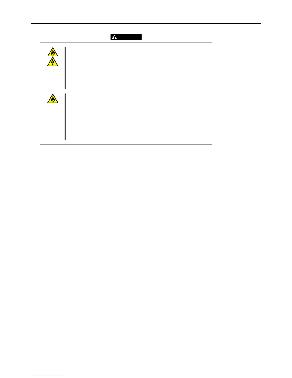
Do not connect any interface cable with the power cord of the server plugged to
a power source.
Make sure to power off the server and unplug the power cord from a power
outlet before installing/removing any optional internal device or
connecting/disconnecting any interface cable to/from the server. If the server is
off-powered but its power cord is plugged to a power source, touching an
internal device, cable, or connector may cause an electric shock or a fire
resulted from a short circuit.
Do not use any unauthorized interface cable.
Use only interface cables provided by Bull and locate a proper device and
connector before connecting a cable. Using an authorized cable or connecting
a cable to an improper destination may cause a short circuit, resulting in a fire.
Also, observe the following notes on using and connecting an interface cable.
Do not use any damaged cable connector.
Do not step on the cable.
Do not place any object on the cable.
Do not use the server with loose cable connections.
Page 24
1-8 Notes on Using Your Server
Cleaning and Working with Internal Devices
WARNING
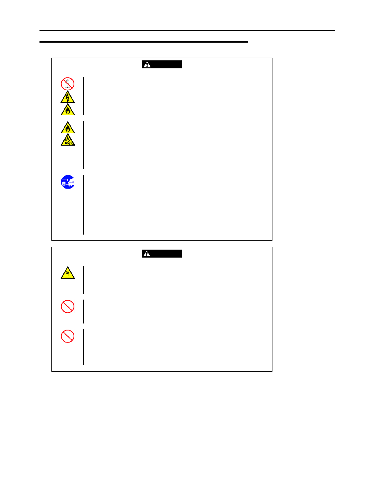
Do not disassemble, repair, or alter the server.
Never attempt to disassemble, repair, or alter the server on any occasion other
than described in this User's Guide. Failure to follow this instruction may cause
an electric shock or fire as well as malfunctions of the server.
Do not remove the lithium battery.
The server contains the lithium battery. Do not remove the battery. Placing the
lithium close to a fire or in the water may cause an explosion.
When the server does not operate appropriately due to the dead lithium battery,
contact your service representative. Do not disassemble the server to replace
or recharge the battery by yourself.
Disconnect the power plug before cleaning the server.
Make sure to power off the server and disconnect the power plug from a power
outlet before cleaning or installing/removing internal optional devices. Touching
any internal device of the server with its power cord connected to a power
source may cause an electric shock even of the server is off-powered.
Disconnect the power plug from the outlet occasionally and clean the plug with
a dry cloth. Heat will be generated if condensation is formed on a dusty plug,
which may cause a fire.
CAUTION
Avoid installation in extreme temperature conditions.
Immediately after the server is powered off, its internal components such as
hard disk drives are very hot. Leave the server until its internal components fully
cool down before installing/removing any component.
Make sure to complete board installation.
Always install a board firmly. An incompletely installed board may cause a
contact failure, resulting in smoking or fire.
Do not touch any electrical components inside the server during the hot-swap
replacement.
All power flows inside the server while the hot-swap replaceable components
(hard disk and power supply). Do not touch the electrical components inside the
server to avoid an electric shock.
Page 25
Notes on Using Your Server 1-9
During Operation
CAUTION
Do not pull out or remove the server from the rack unnecessarily.
Do not pull out or remove the server from the rack unnecessarily. Pulling out or
removing the server from the rack may cause not only the server to operate
incorrectly but also the server to fall on people to make them injured.
Stay away from the fan.
Keep your hand or hair away from the cooling fan on the rear of the server.
Failure to follow this warning may get your hand or hair caught in the fan,
resulting in injury.
Avoid contact with the server during thunderstorms.
Disconnect the power plug from the outlet when a thunderstorm is approaching.
If it starts thundering before you disconnect the power plug, do not touch any
part of the server including the cables. Failure to follow this warning may cause
a fire or an electric shock.
Keep animals away from the server.
Failure to follow this warning may cause a fire or an electric shock.
Do not place any object on top of the server.
The server may fall and cause property damage to the surroundings.
Do not leave the server with its optical disk drive tray ejected.
Dust may enter the server through openings and cause malfunctions of the
server. Any person may also bump it and get injured.
Page 26

1-10 Notes on Using Your Server
FOR PROPER OPERATION
Observe the following notes for successful operation of the server. Use of the server ignoring the notes will cause malfunctions
or failures of the server.
Install the rack assembly in a place that meets requirements for successful operation. For details, see Chapter 3,
"Setting Up Your Server."
The server is intended for installation in a Restricted Access Location, mounted above a non-combustible material.
Make sure to power off the server before connecting or disconnecting cables between the server and peripheral
devices.
Verify that the access LED on the server is unlit before turning off the server or ejecting the floppy disk.
The server management logic on your system board monitors and logs system voltage changes. When plugging the
power cord to the system, you may experience 30 seconds delay from the time you press the POWER switch on the
front panel. This is normal system operation and is required by the server management logic.
Do not turn off the server until the POST (Power On Self-Test) completes. See Chapter 2 for details of POST.
When you have just turned off the server, wait at least 30 seconds before turning it back on.
When unplug the power cord(s) from the server, wait at least 30 seconds before re-pluging the power cord(s) to the
server.
Turn off the power and unplug the power cord from the outlet before relocating the server.
Clean the server on a regular basis. (See Chapter 7 for cleaning.) Regular cleaning proactively prevents various
failures of the server.
Lightning may cause a momentary voltage drop. To prevent this problem, it is recommended to use of an
uninterruptible power supply unit.
Check and adjust the system clock before the operation if any of the following conditions is applicable.
– After carriage of device
– After storage of device
– After the device is entered into the pause state under the environmental condition enduring device operation
(temperature: 10°C - 35°C, humidity: 20% - 80%)
Check the system clock at the rough rate of once per month. When the system clock is installed in a system requiring
high time precision, it is recommended to use a time server (NTP server).
If the system clock is remarkably delayed or advanced as the passage of time in spite of adjustment, contact your
service representative to ask maintenance.
Page 27

Notes on Using Your Server 1-11
Store the unit under the storage condition (temperature: –10°C - 55°C, humidity: 20% - 80%, without condensation)
to allow built-in devices and the unit to operate correctly in the next operation.
Make sure to use optional devices supported by the server. Some non-supported devices may be physically
installed/connected but cause failures of the server as well as a malfunction of the server.
Bull recommends you use Bull's genuine products. Some third-party products claim that they support the server.
However, repair of the server due to a failure or damage resulted from use of such third-party products will be
charged.
Turn off the cellular phone or pager. Radio interference may cause malfunctions of the server.
Page 28

1-12 Notes on Using Your Server
TRANSFER TO THIRD PARTY
The following must be observed when you transfer (or sell) the server or software provided with the server to a third party:
Server Hardware
Make sure to provide this User's Guide along with the server to a third party.
Provided Software
To transfer or sell any software application that comes with the server to a third party, the following requirements must be
satisfied:
All provided software applications must be transferred and no backup copies must be retained.
Transfer requirements listed in "Software License Agreement" that comes with each software application must be
satisfied.
Software applications that are not approved for transfer must be uninstalled before transferring the server.
Page 29
Notes on Using Your Server 1-13
DISPOSAL AND CONSUMABLES
Dispose the server, all the internal devices and DVD-ROMs according to all national laws and regulations.
IMPORTANT: For disposal (or replacement) of the battery on the mother board of the server,
consult with your service representative.
The server contains some components that are only good for a limited period of time and require replacement, such
as fans, internal batteries, the internal optical disk drive, and the mouse. For stable operation of the server, Bull
recommends you replace these components on a regular basis. Consult with your service representative for
replacement or the product lives.
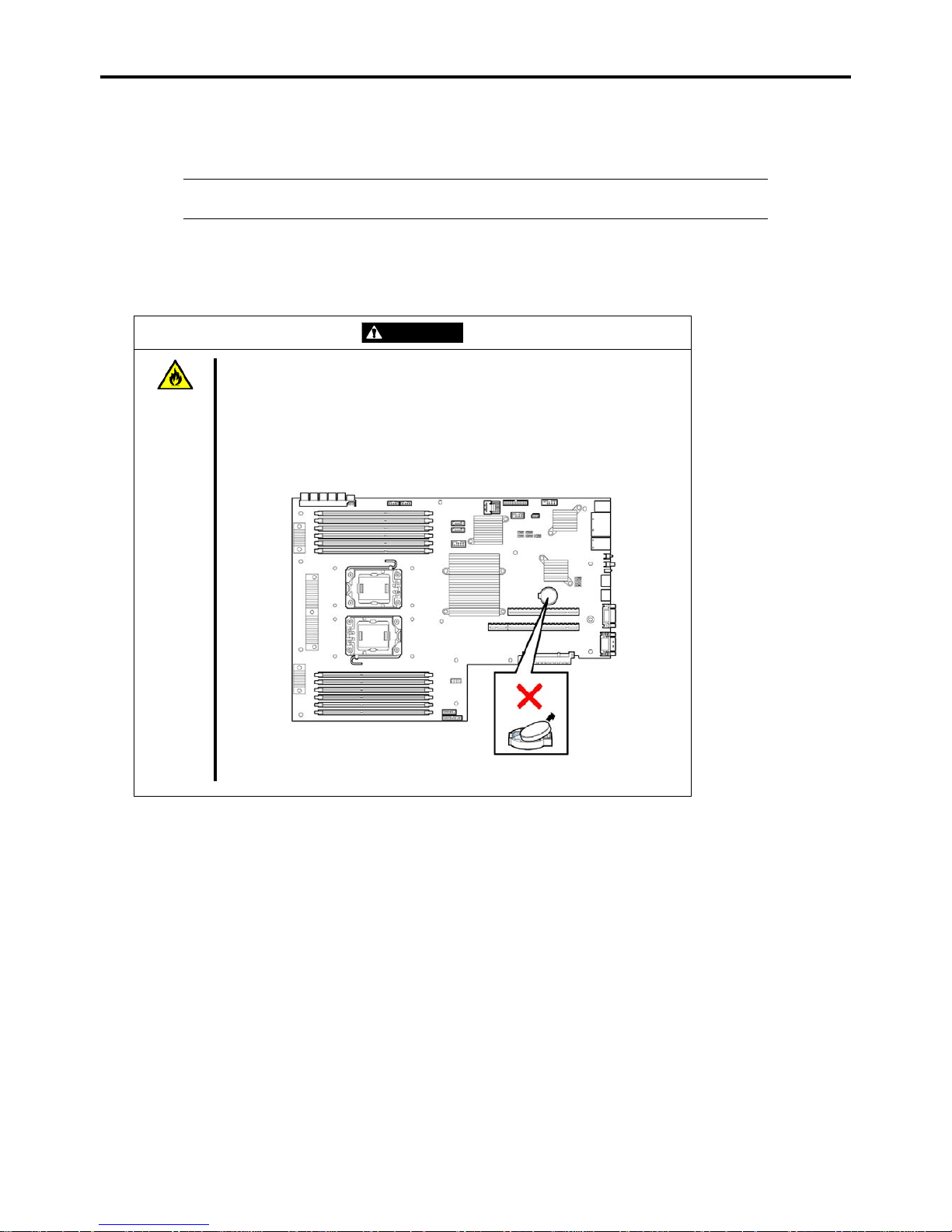
WARNING
Do not remove the lithium battery.
The server contains the lithium battery. Do not remove the battery. Placing the
lithium or nickel cadmium battery close to a fire or in the water may cause an
explosion.
When the server does not operate appropriately due to the dead lithium battery,
contact your service representative. Do not disassemble the server to replace or
recharge the battery by yourself.
Mother board
Page 30

1-14 Notes on Using Your Server
USER SUPPORT
Before asking for repair, do the following when the server appears to fail:
1. Check if the power cord and the cables to other devices are properly connected.
2. See Chapter 8 to find if your problem fits the description. If it does, take the recommended measure for it.
3. Check if the software required for operation of the server is properly installed.
If the server still appears to fail after you have taken the above actions, contact your service representative immediately. Take
notes on LED indications of the server and alarm indications on the display unit before consultation, which may provide a
significant help to your service representative.
Page 31
Notes on Using Your Server 1-15
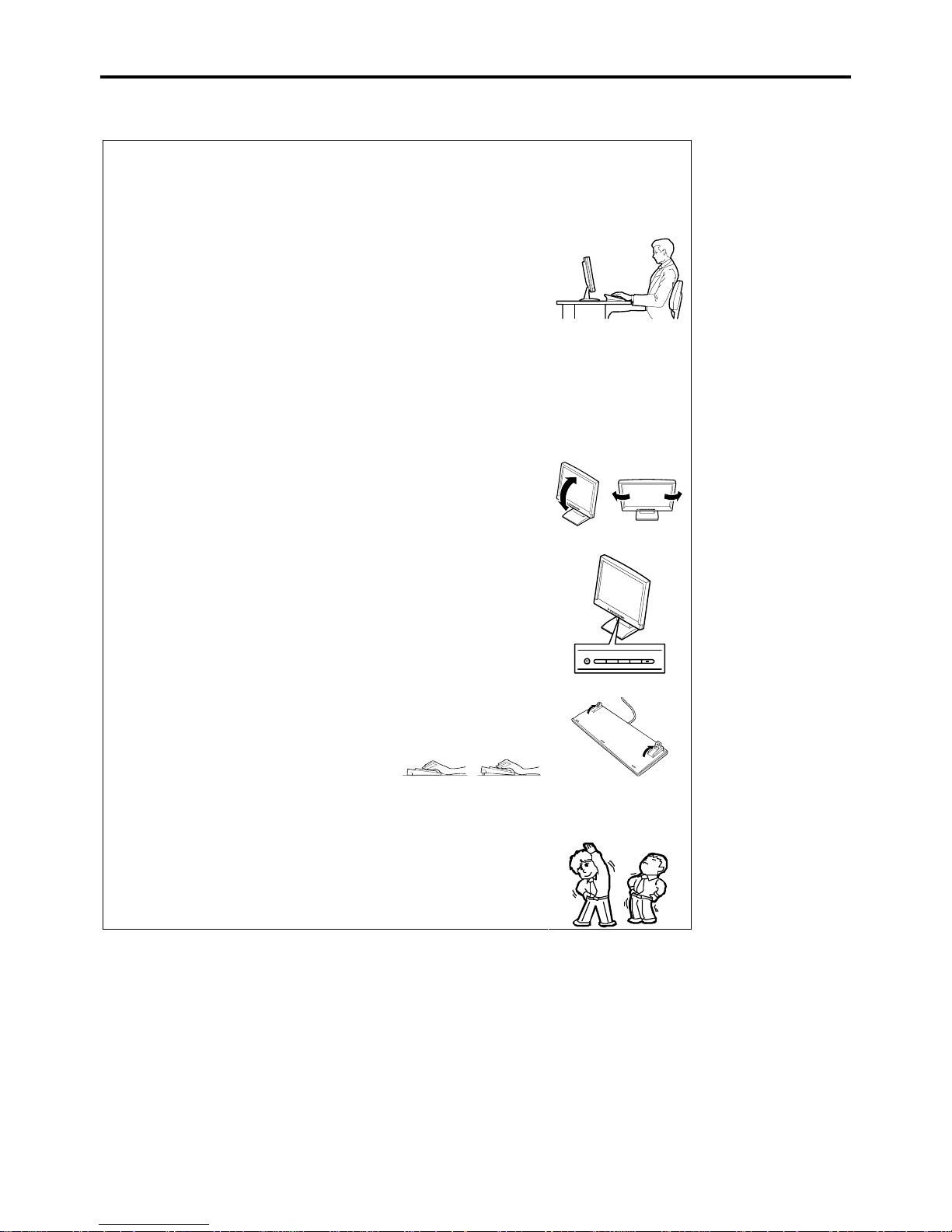
Advice for Health
The longer you keep using the computer equipment, the more you
become tired, which may cause disorders of your body. When you use a
computer, observe the following to keep yourself from getting tired:
Good Working Posture
You have good posture if the following are satisfied when you use a
computer:
• You sit on a chair with your back straight.
• Your hands are parallel with the floor when you put them on the
keyboard.
• You look at the screen slightly lower than your eye height.
You have "good working posture" as described in the above when no part
of your body is under excess strain, in other words when your muscles
are most relaxed.
You have "bad posture" when you sit with your back hunched up or you
operate a display unit with your face close to the screen. Bad working
posture may cause eye strain or poor eyesight.
Adjustment of Display Unit Angles
Most display units are designed for adjustment of the horizontal and
vertical angles. This adjustment is important to prevent the screen from
reflecting bright lights and to make the display contents easy to see. You
will not be able to keep "good working posture" and you will feel more
tired than you should if you operate a display unit without adjusting
horizontal and vertical angles.
Adjustment of Screen Brightness and Contrast
The display unit has brightness and contrast adjustment functions. The
most suitable brightness and contrast depend on the individual and the
working environment (well-lighted room or insufficient light). Adjust
brightness and contrast so that the screen will be easy to see. An
extremely bright or dark screen will give a bad effect to your eyes.
Adjustment of Keyboard Angle
The keyboard provided with the server is designed for adjustment of an
angle. Adjust the keyboard angle at which the keyboard is easy to
operate. The adjustment assists in reducing strain on your shoulders,
arms, and fingers.
Cleaning of Equipment
Clean equipment regularly. It is difficult to see the display contents on a
dusty screen. Keeping equipment clean is also important for your sight.
Fatigue and Rest
If you feel tired, you should stop working and do light exercises.
Page 32

1-16 Notes on Using Your Server
Page 33

Chapter 2
General Description
This chapter provides information that you should be familiar with before using the server. It includes names and functions of
the components and features of the server.
Page 34
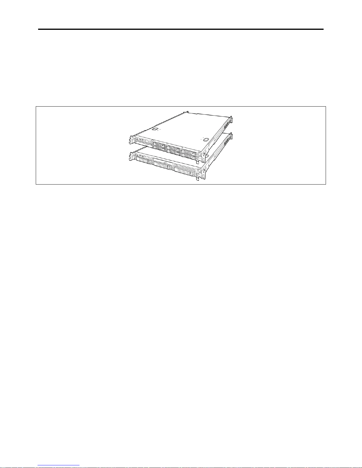
2-2 General Description
OVERVIEW
Your server NovaScale R440 E2 is a modular, multiprocessing server based on the Intel® Xeon® microprocessor. It is a solid
performer and offers the latest technology. The combination of compute performance, memory capacity, and integrated I/O
provides a high performance environment for many server market applications. These range from large corporations supporting
remote offices to small companies looking to obtain basic connectivity capability such as file and print services, e-mail, web
access, web site server, etc.
Your server is housed and available as a rack-mount system. Your server conveniently installs into a standard EIA 19-inch rack
assembly.
Your server includes an optical disc drive and three (SATA or SAS) or six (SAS) hard disk drive bays. The hot-swap hard disk
drive bays support hard disk drives that can be swapped in or out of the system without powering it down, if RAID
functionality is configured in the system.
As application requirements increase, you can expand your server with an additional processor, additional memory, add-in
boards and peripheral devices, and hard disk drives.
Page 35
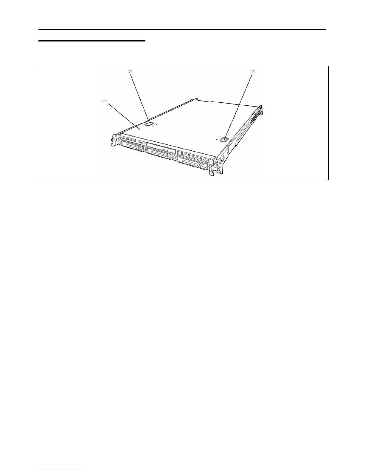
General Description 2-3
External View
The following figure shows the 3.5-inch disk model.
1 Top cover
Remove the top cover to install/remove DIMM, CPU, or PCI boards.
2 Release buttons
Push these buttons to remove the top cover.
Page 36
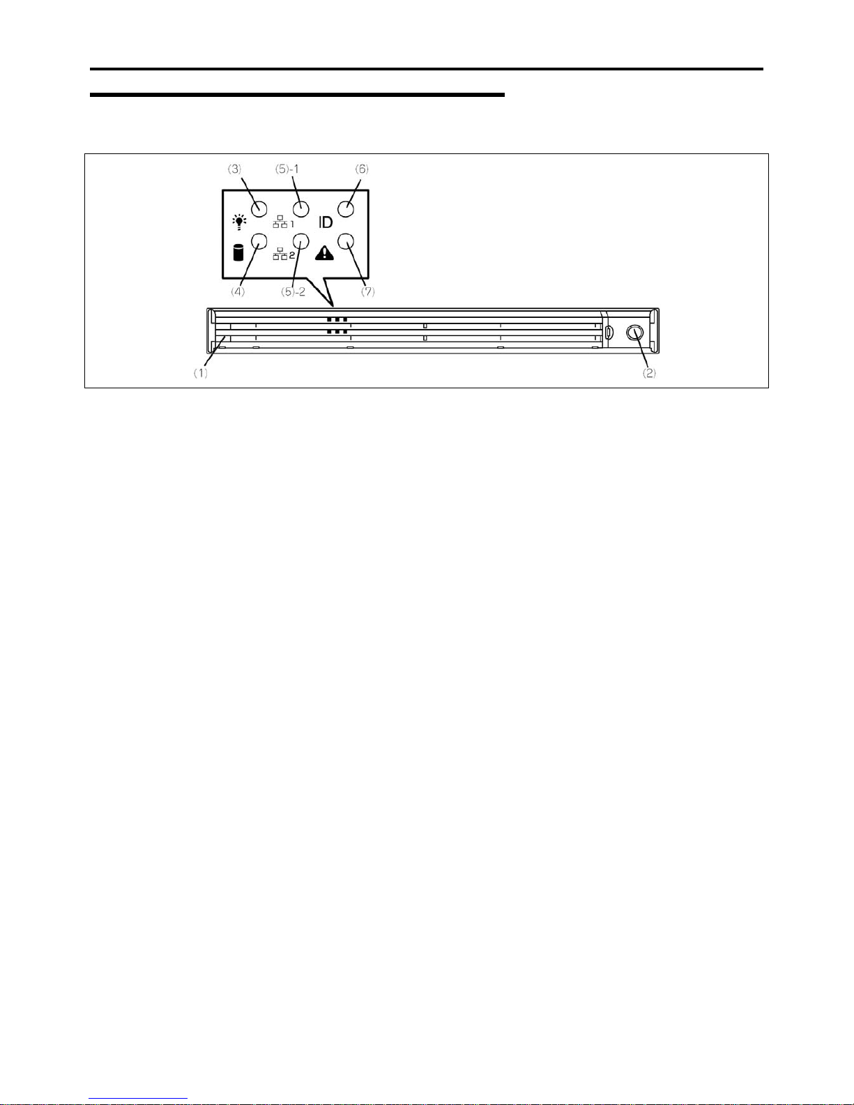
2-4 General Description
Front View with Front Bezel Closed
The following figure shows the location of the front system features.
1 Front bezel
The front bezel is a cover protecting the front devices during daily operation. A security key is
provided to lock the cover.
2 Key slot
Insert the security key into this slot when unlocking the front bezel.
3 POWER LED (green)
This LED turns green when the power is turned on. It flashes while the server is in standby
mode.
4 DISK ACCESS LED (green/amber)
This LED is green during access to the internal hard disk drives. The LED turns amber when
one of the internal hard disk drives fails.
5 ACT LED (green)
This LED is on while the system is connected to the network. The number "1" on the icon
indicates LAN port 1, and the number "2" indicates LAN port 2.
6 UID LED (blue)
This LED goes on when the UID switch is pressed. (The LED also goes on or flashes when
software issues a command.)
7 STATUS LED (green/amber) (on the front panel)
This LED indicates the server status. The LED is green during normal operation. The LED
turns amber or flashes when the server enters the abnormal state.
Page 37
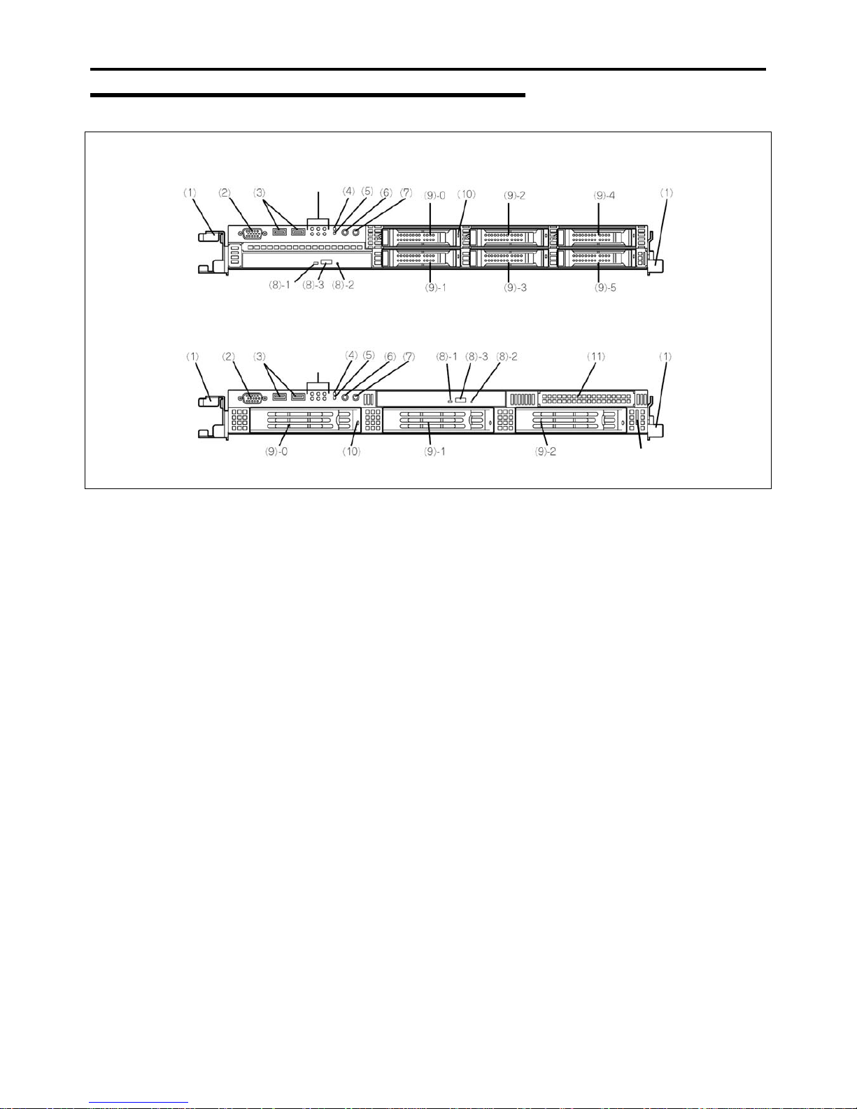
General Description 2-5
Front View with Front Bezel Removed
2.5-inch disk model
3.5-inch disk model
(12)
1 Handles (1 on each side)
Hold the handles when dismounting/mounting the server from/in the rack.
2 Monitor connector
Connect the display unit to this connector. Do not use it if the one on the rear panel is already
connected to a monitor.
3 USB connectors (2 ports)
Connect devices compliant with the USB interface to the connectors.
4 RESET switch
Press this switch to reset the server.
5 DUMP (NMI) switch
Press this switch to dump system memory.
6 POWER switch
Press this switch to turn on/off the power. Pressing the switch once turns on the power, and
the POWER LED goes on. Pressing it again turns off the power. Keep pressing the switch for
4 seconds or more forcibly turns off the power.
7 UID (Unit ID) switch
Press this switch to turn on/off the UID LEDs on the front and rear panels of the server.
Pressing the switch once turns on the LEDs. Pressing it again turns them off.
(The LED also goes on or flashes when software issues a command.)
8 Optical disk drive
This drive reads data from the disc.
8-1 Disk access LED 8-2 Emergency eject hole 8-3 Tray eject button
9 Hard disk drive bays
Mount hard disk drives in the bays. The last digit indicates the channel number. The hard
disk drives must be purchased separately.
3.5-inch disk model: up to 3 drives
2.5-inch disk model: up to 6 drives
10 DISK LED (green/amber)
Hard disk drive LED. Each hard disk drive LED is green during access to the hard disk drive.
The LED turns amber when the hard disk drive fails. The LED flashes switching back and
forth between green and amber during build processing (only in RAID System).
11 Floppy disk drive bay
Install an optional floppy disk drive or a battery for RAID Controller in this slot. They are
mutually exclusive.
12 Slide tag
A label for indicating the serial number or name of the server.
Page 38
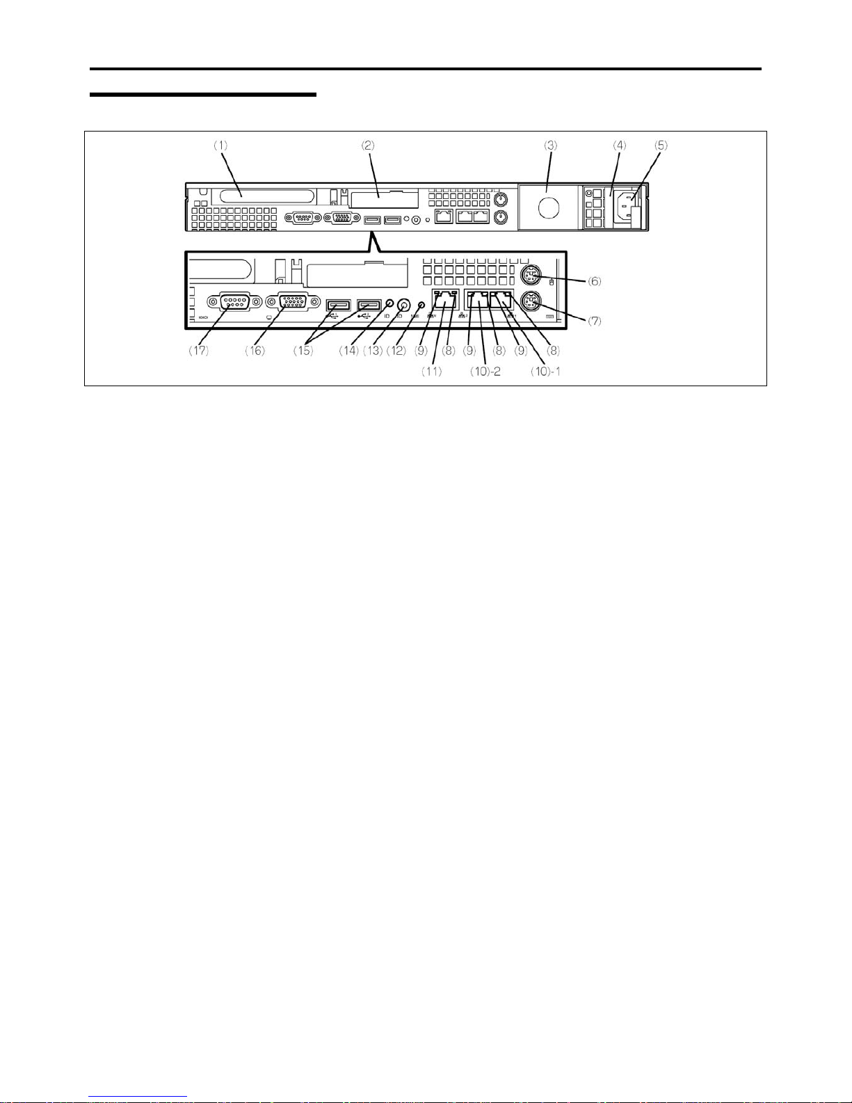
2-6 General Description
Rear View
1 Full-height PCI board slot
Mount PCI board of the full-height type in the slot.
2 Low-profile PCI board slot
Mount PCI board of the low-profile type into this slot.
NOTE: If an additional LAN board is installed, it is hard to push the catch of the connector
with your finger that is connected to the LAN board. Disconnect the connector
pushing the catch with a standard screwdriver. At this time, be very careful for the
screwdriver not to damage the LAN board.
3 Blank panel (for additional power supply unit)
Install an optional power supply unit in this slot.
4 Power supply unit
Factory-installed power supply unit
5 AC inlet
Connect the power cord to this socket.
6 Mouse connector
Connect the mouse to this connector.
7 Keyboard connector
Connect the keyboard to this connector.
8 LINK/ACT LED (green)
This LED indicates the access status of the LAN.
9 Speed LED (green/amber)
This LED indicates the transmission speed of the LAN.
10 LAN connectors
Connect network systems on the LAN to the connectors
(1000BASE-T/100BASE-TX/10BASE-T).
The number "1" following the parenthesized number indicates LAN port 1, and the number
"2" indicates LAN port 2.
If [Shared BMC LAN] is set to [Enabled] in BIOS SETUP, the LAN port 2 can be used as
management LAN, and not only as a transmission port. However, it is not recommended for
performance and security reasons, because the LAN port 2 may receive both normal data
and management data.
Page 39

General Description 2-7
11 Management LAN port
100BASE-TX/10BASE-T interface port used to manage the server via LAN.
12 DUMP (NMI) switch
Press this switch to dump system memory.
13 UID switch
Press this switch to turn on/off the UID LEDs on the front and rear panels of the server.
Pressing the switch once turns on the LEDs. Pressing it again turns them off.
14 UID LED (blue)
This LED goes on when the UID switch is pressed. (The LED also goes on when software
issues a command.)
15 USB connectors
Connect device compliant with the USB interface to this connector.
16 Monitor connector
Connect the display unit to this connector. Do not use it if the one on the front panel is
already connected to a monitor.
17 Serial port (COM) connector
Connect devices having a serial interface to this connector.
A leased line cannot be connected directly to this connector.
Page 40
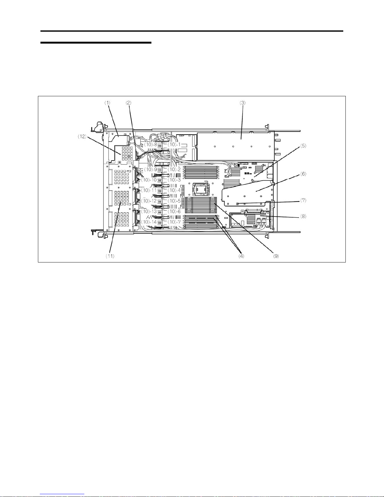
2-8 General Description
Internal View
The internal view for each model is shown below. For a better viewing, the processor air duct that is installed at fatory has
been removed.
2.5-inch Disk Model
1 Front panel board
2 Backplane
3 Power supply unit
4 DIMM sockets
5 Mother board
6 PCI riser card
7 Top cover open sensor
8 RAID controller
9 Processor (below the heat sink)
10 Cooling fans
10-1 FAN1R 10-2 FAN2R 10-3 FAN3R 10-4 FAN4R
10-5 FAN5R 10-6 FAN6R 10-7 FAN7R 10-8 FAN1F
10-9 FAN 2F 10-10 FAN3F 10-11 FAN4F 10-12 FAN5F
10-13 FAN6F 10-14 FAN7F
11 Hard disk drive bays
12 Optical disk drive
Page 41
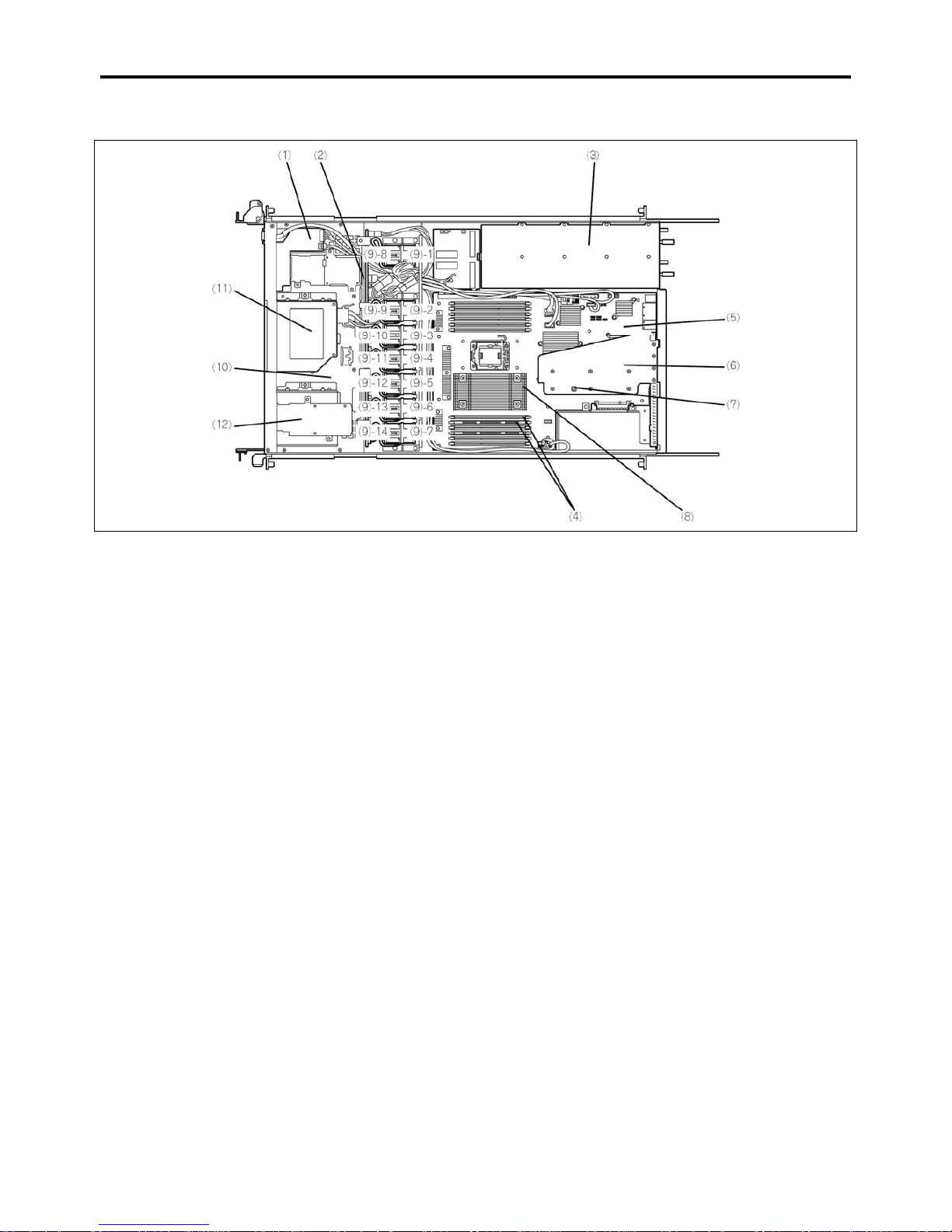
General Description 2-9
3.5-inch Disk Model
1 Front panel board
2 Backplane
3 Power supply unit
4 DIMM sockets
5 Mother board
6 PCI riser card
7 Top cover open sensor
8 Processor (below the heat sink)
9 Cooling fans
9-1 FAN1R 9-2 FAN2R 9-3 FAN3R 9-4 FAN4R
9-5 FAN5R 9-6 FAN6R 9-7 FAN7R 9-8 FAN1F
9-9 FAN 2F 9-9 FAN3F 9-11 FAN4F 9-12 FAN5F
9-13 FAN6F 9-14 FAN7F
10 Hard disk drive bays
11 Optical disk drive
12 Floppy disk drive bay
Install an optional floppy disk drive in th is bay
Page 42
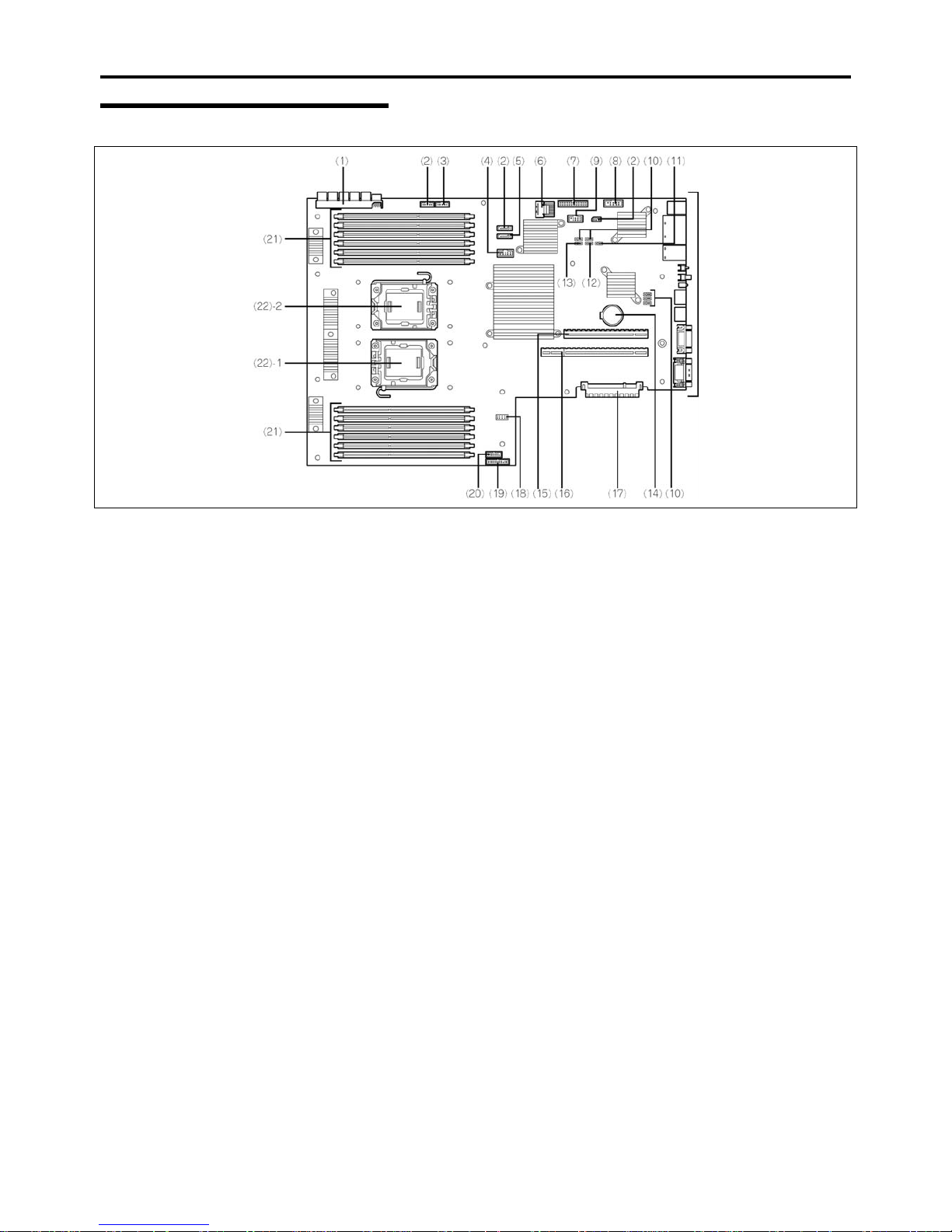
2-10 General Description
Mother Board
External
connectors
REAR
FRONT
1 Power connector
2 Unused connector
3 USB Floppy Disk Drive connector
4 USB connector (front)
5 SATA DVD connector
6 SATA HDD connector
Used only when 3.5-inch SATA2 hard disk drive is installed.
7 Fan connector
8 Option COM connector
9 HDD BP connector
10 Unused jumper switch
11 CMOS clear jumper switch
12 Password clear jumper switch
13 RAID configuration jumper switch
With 2.5-inch disk model, leave the factory setting as is.
14 Lithium battery
15 Connector for PCI riser card slot (for low-profile board)
16 Connector for PCI riser card slot (for full-height board)
(See Chapter 9 for available
boards.)
17 Connector for RAID controller
18 USB memory module connector
19 Front panel connector
20 Front video connector
21 DIMM sockets
22 Processor sockets
22-1 Processor #1 (CPU#1) 22-2 Processor #2 (CPU#2)
Page 43
General Description 2-11
STATUS INDICATORS
This section explains the indication and meanings of the server LEDs.
POWER LED ( )
The POWER LED is on (green) while the server is being powered. It is off while no power is supplied to the server. It flashes
while the server is in standby status.
STATUS LED ( )
The STATUS LED is on (green) while the server is operating normally. If the STATUS LED is off or turns amber and flashes,
it indicates that the server is in abnormal state.
The table below explains the STATUS LED indication, the meanings, and the procedures.
NOTES:
If NEC ESMPRO is installed, you can confirm the cause of a failure by referring to the error
log.
If shutdown processing can be performed through the operating system when you want to
restart the system after turning the power off, then restart the system by performing shutdown
processing. If shutdown processing cannot be performed, restart the system by resetting,
forcibly turning the power off, or disconnecting and then connecting the power cord.
Page 44
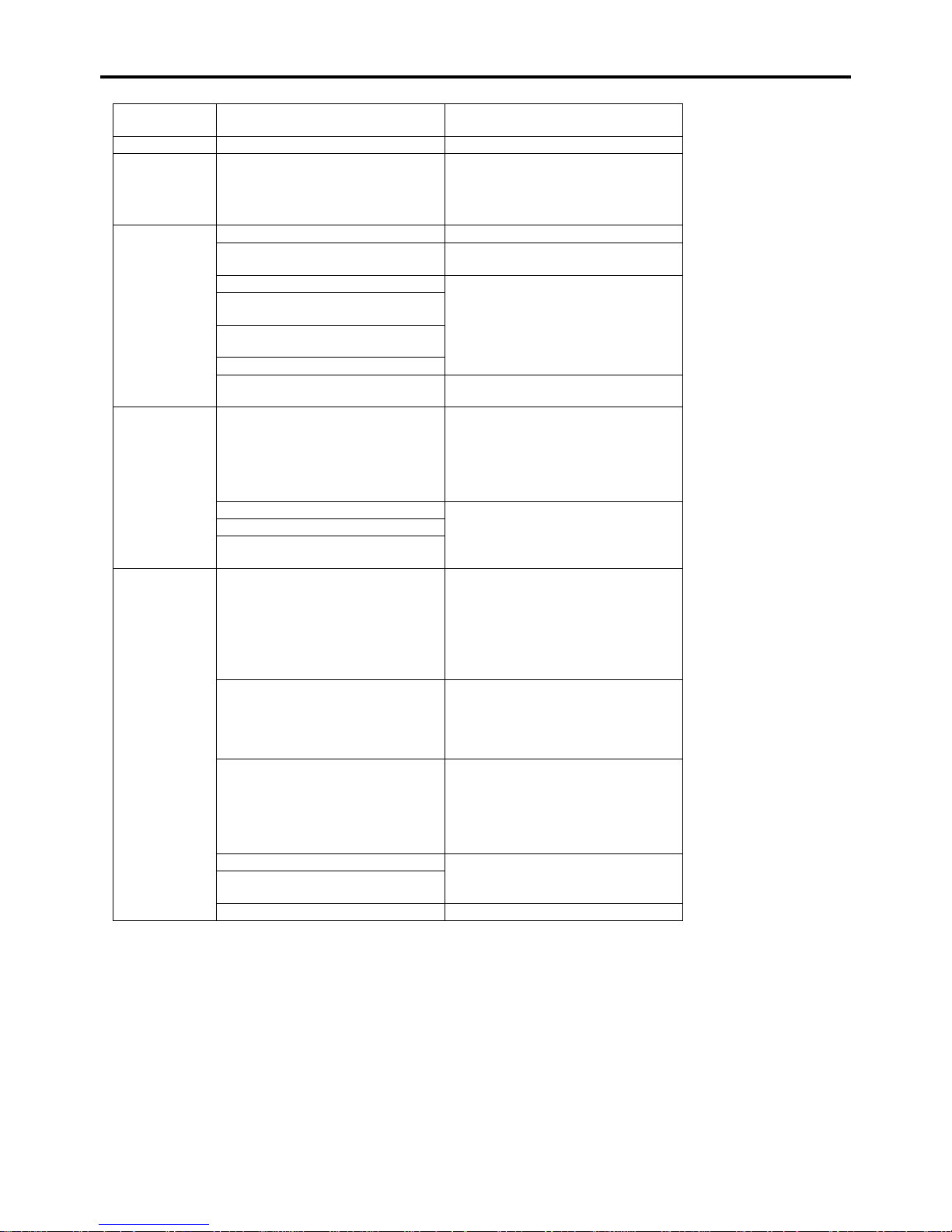
2-12 General Description
STATUS LED
indication
Description Procedure
On (green) The server is operating normally. –
Flashing
(green)
• The server is operating with the
memory in degraded state.
• An uncorrectable memory error
has often occurred.
Identify the device in degraded state
by using the BIOS setup utility
"SETUP," and replace it as soon as
possible.
The power is off. –
POST is in progress.
Wait for a while. The STATUS LED
turns green when POST is completed.
A CPU error occurred. (IERR)
A CPU temperature alarm was
detected.
A timeout occurred when the time
set for the watchdog timer arrived.
A CPU bus error occurred.
Turn the power off and then turn it on.
If the POST screen displays an error
message, take notes of the message,
and contact your sales representative.
Off
A memory dump request is made.
Wait until the memory dump is
completed.
A temperature alarm was detected.
Check if the internal fans are clean
and if the fan units are firmly
connected.
If the STATUS LED indication does
not change when the fans are normal,
contact your sales representative.
A voltage alarm was detected.
All the power supply units failed.
On (amber)
A temperature alarm was detected
on chipset.
Contact your sales representative.
Flashing
(amber)
Either of the following was detected
in the redundant power
configuration:
• AC power not supplied to one of
the two power supply units
• Failure of one of the two power
supply units
Connect the power cord to supply
power. If the power supply unit is
faulty, contact your service
representative.
A fan alarm was detected.
Check if the fan units are firmly
connected.
If the STATUS LED indication does
not change when the fans are normal,
contact your sales representative.
A temperature warning was
detected.
Check if the internal fans are clean
and if the fan units are firmly
connected.
If the STATUS LED indication does
not change when the fans are normal,
contact your sales representative.
A voltage warning was detected Contact your service representative.
An error was detected on either of
the hard disk drives.
Detected that the top cover is open. Check if the top cover is open or not.
Page 45
General Description 2-13
DISK ACCESS LED ( )
The DISK ACCESS LED indicates the status of the hard disk drive mounted in the disk bay.
The LED turns green each time access is made to the hard disk drive.
When the DISK ACCESS LED turns amber, it indicates that a hard disk drive failure has occurred. Check the hard disk drive
LED for the status of the failing hard disk drive.
ACT LED ( )
The ACT LED is green while the server is connected to the LAN. The LED flashes while the server is accessed via the LAN
(during transmission/reception of packets). The number next to the icon indicates the network port number on the rear panel of
the server.
UID LED (UID)
Pressing the UID switch toggles the front panel UID LED (blue) and the mother board UID LED on and off. The mother board
UID LED is visible through the rear of the chassis and allows you to locate the server you're working on from the rear of the
servers in a rack.
Disk Access LED
The disk access LED of the optical disk drive is on while the drive is accessed.
Page 46
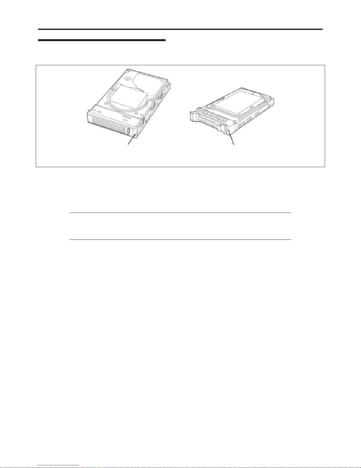
2-14 General Description
Hard Disk Drive LED
The disk LED located on the drive carrier indicates the following depending on the status:
Disk LED
Disk LED
3.5-inch hard disk drive 2.5-inch hard disk drive
Flashing (green)
The LED indicates that the hard disk drive is being accessed.
On (amber)
The LED indicates a failure of a hard disk drive mounted in RAID System.
NOTE: Even if one (two hard disk drives in RAID6) of the hard disk drives fails in Logical Drive
(RAID1, RAID5, or RAID6), the server can continue operation. However, replace the hard disk
drive as soon as possible, and perform reconstruction (rebuild) processing. (The failing hard disk
drive can be replaced in hot swap mode.)
Flashing switching back and forth between green and amber
The LED indicates that reconstruction (rebuild) processing is being performed for the hard disk drive. (This flashing
does not indicate a failure.) When a failing hard disk drive is replaced in RAID System, the system automatically
rebuilds the data. (Auto-rebuild function) The LED switches back and forth between green and amber during rebuild
processing.
The LED goes off when the rebuild processing has terminated. It turns amber when the rebuild processing fails.
Page 47
General Description 2-15
IMPORTANT: If the server is turned off during rebuild processing, the processing is stopped.
Restart the server, mount the new hard disk drive in hot swap mode, and then perform rebuild
processing again. Observe the following notes on using the auto-rebuild function.
Do not turn the power off. (Once the power is turned off, the auto-build function does not
start.)
Let 90 seconds or more pass between when dismounting a failing hard disk drive and when
mounting the new one.
Do not replace a failing hard disk drive while rebuild processing is being performed for another
hard disk drive.
Page 48
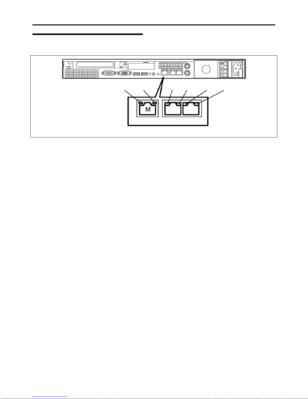
2-16 General Description
LAN Connector LEDs
There are two LEDs for each of the two LAN ports (connectors) on the rear panel.
LINK/ACT
SPEED SPEED
SPEED LINK/ACT
LINK/ACT
Data transmission ports
Management port
LINK/ACT LEDs
Each LINK/ACT LED indicates the status of the standard network port of the server. While power is supplied to the
server and HUB and the connection is correct, the LED is on (green). The LED turns green and flashes while the
network port is transmitting/receiving data.
If the LED does not go on when the LINK state is placed, check if the network cable is in normal state and if it is
connected correctly. If the LED does not go on yet when the network cable is normal, the network (LAN) controller
may be faulty. In this case, contact your sales representative.
Speed LEDs (for data transmission ports)
This LED indicates whether each of the network ports normally equipped with the server is operated through the
1000BASE-T, 100BASE-TX or 10BASE-T network interface. If the LED is lit amber, the network port is operated
through 1000BASE-T. If the LED is lit green, the network port is operated through 100BASE-TX. If the LED is off,
the network port is operated through 10BASE-T.
Speed LED (for management port)
This LED indicates whether each of the network ports normally equipped with the server is operated through the
100BASE-TX or 10BASE-T network interface. If the LED is lit green, the network port is operated through
100BASE-TX. If the LED is off, the network port is operated through 10BASE-T.
Page 49
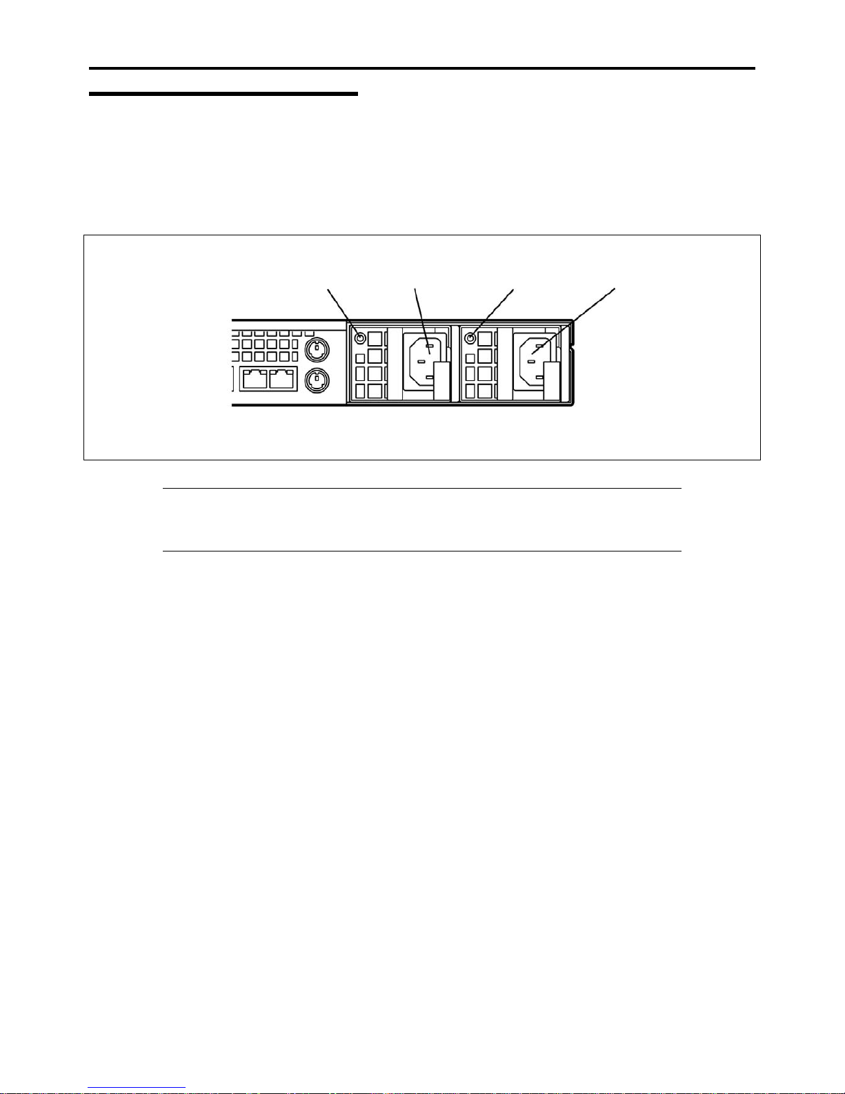
General Description 2-17
AC POWER LED
There is an AC POWER LED for the power supply unit on the rear. The LED turns green and flashes when the power supply
unit receives AC power from the power cord, which is connected to the AC inlet. (Flashing amber indicates no AC power is
received in any one of two power supplies in the redundant configuration.)
The LED turns green when the server power switch is turned on. If the LED does not go on when the server power switch is
turned on or if it turns amber, the power supply unit is probably faulty. In this case, contact your service representative to
replace the power supply unit.
AC POWER LED
AC POWER LED
AC inlet
AC inlet
Power supply
slot (option)
Power supply
slot (standard)
NOTE: If one power supply unit fails while an optional power supply is mounted, the system can
continue operation with the other power supply unit (redundant function). The failing power
supply unit can be replaced in hot swap mode (with the power on) without the system being
stopped.
Page 50
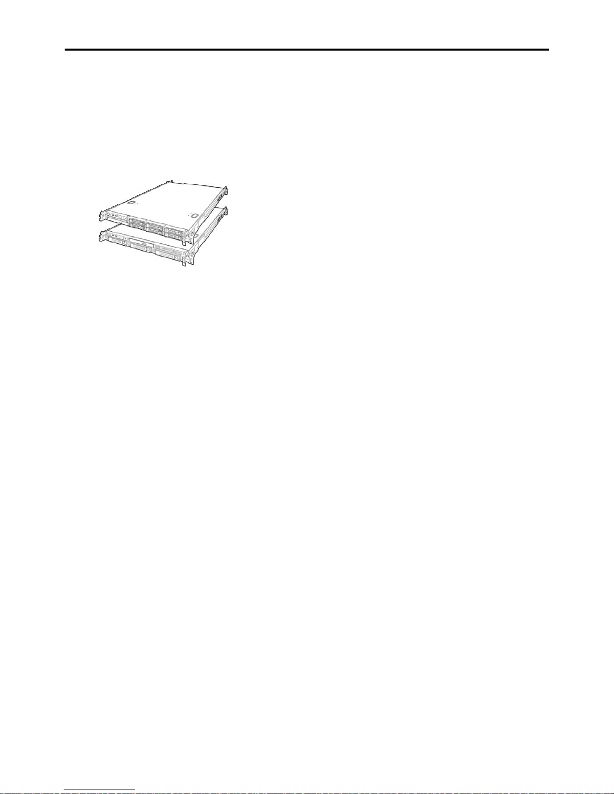
2-18 General Description
STANDARD FEATURES
High performance High-reliability
Intel® Xeon® Processor
1.86GHz and above
High-speed memory access (DDR3 1066)
High-speed network interface
(1000Mbps/100Mbps/10Mbps supported)
High-speed disk access
(SATAII 300/Serial Attached SCSI)
*1
Memory monitoring feature (error
correction/error detection)
CPU/memory degradation feature (logical
isolation of a failed device)
Memory x4/x8 SDDC feature
Memory mirroring/LockStep feature
(x8 SDDC)
Bus parity error detection
Temperature detection
Error notification
Internal fan monitoring feature
Internal voltage monitoring feature
Redundant power supply (hot-swap)
Onboard RAID Controller (LSI Embedded
MegaRAID)
Internal RAID Controller
Auto-rebuild feature (hot-swappable)
BIOS password feature
Mechanical security lock
Redundant fans
Expandability Many Available Features
Redundant power supply feature (with
optional power supply unit installed)
El Torito Bootable CD-ROM (no emulation
mode) format support
POWER switch mask
Software power-off
Remote power-on feature
AC-Link feature
Remote console feature
Front monitor connector
Self-diagnosis
PCI Express 2.0 (x16): 1 slot (full height)
PCI Express 2.0 (x8): 1 slot (low profile)
*2
PCI Express 2.0 (x4): 1 slot (Dedicated to RAID
Controller)
*2
Can be changed to PCI-X133 slot by using the
optional riser card.
Large memory of up to 48GB (with one CPU) or
up to 96GB (with two CPUs)
Up to two multi-processors are available for
upgrade.
Three network ports (one for management
LAN)
Hard disk drive bays
3.5-inch disk model: up to 3 hard disk drives
2.5-inch disk model: up to 6 hard disk drives
One backup file bay
USB2.0 interface
Power On Self-Test (POST)
Test and Diagnosis (T&D)
Management Utilities Easy and Fine Setup
NEC ESMPRO
RAID System Management Utility (Universal
RAID Utility)
Hard disk drive monitoring feature
ExpressBuilder (system setup utility)
Parameter File Creator
SETUP (BIOS configuration utility)
Maintenance Features
Off-line Maintenance Utility
Memory dump feature using the DUMP switch
*1 2.5-inch disk model server supports SAS hard
disk drive only
*2 Connector for 8-lane is used.
Power saving and noiseless design
Power monitoring feature
Power control feature
High-efficiency power supply supporting 80
PLUS®
Fan control appropriate to environment, work
load, and configuration
Noiseless design
Page 51

General Description 2-19
Remote Management Feature
Server management is concentrated in the Remote Management Controller (RMC). The RMC and associated circuitry are
powered from a 5Vdc standby voltage, which remains active when system power is switched off, but the ac power source is
still on and connected.
The RMC supports the NEC ESMPRO Manager, which allows remote server management through networks. Events
monitored by the manager system include over-temperature and over-voltage conditions, fan failure, or chassis intrusion.
Information on NEC ESMPRO Manager may be found in the ExpressBuilder DVD.
One major function of the RMC is to autonomously monitor system management events, and log their occurrence in the
nonvolatile System Event Log (SEL). The events being monitored include over temperature and overvoltage conditions, fan
failure, or chassis intrusion. To enable accurate monitoring, the RMC maintains the nonvolatile Sensor Data Records (SDRs),
from which sensor information can be retrieved. The RMC provides an ISA host interface to SCR sensor information, so that
software running on the server can poll and retrieve the server's current status.
The RMC performs the following:
Monitors server board temperature and voltage*
Monitors processor presence and controls Fault Resilient Boot (FRB)
Detects and indicates baseboard fan failure*
Manages the SEL interface
Manages the SDR Repository interface
Monitors the SDR/SEL timestamp clock
Monitors the system management watchdog timer
Monitors the periodic SMI timer
Monitors the event receiver
Controls secure mode, including video blanking, diskette write-protect monitoring, and front panel lock/unlock
initiation
Controls Wake On LAN via Magic Packet support.
Monitors the hard disk drives
Verifies system configuration data (CPU, memory, and others)
*Also, NEC ESMPRO supports these features.
Page 52
2-20 General Description
Degradation Feature
The degradation feature automatically isolates a failed DIMM or processor to assure continuous operation of the server when
the POST (Power On Self-Test, self-diagnosis program after power on) detects such a DIMM or processor.
NOTE: The degradation feature is only available when at least two DIMMs or processors are
installed.
Failed DIMMs and processors may be identified on the screen that the POST displays, or with the BIOS setup utility of the
server, "SETUP." They may also be identified on the system that has the NEC ESMPRO installed.
Memory RAS Features
Your server board has the memory mirroring and LockStep features. For detail explanation, refer to Chapter 9.
Remote Power-On Feature (Wake On LAN)
The remote power-on function turns on the server through a network. It sends a special packet from the management computer
to a remote server to turn it on if the server is off-powered.
To enable this feature, use the BIOS setup utility, "SETUP." (See Chapter 4.)
The remote power-on feature is not available in the following cases. Press the POWER switch once to start the OS, and turn off
the server in an appropriate procedure.
Abnormal previous system shut-down
No power supply to the server (due to turned-off breaker, disconnected power cord, power blackout, etc.)
AC-Link Feature
When the power cord of the server is connected to an uninterruptible power supply (UPS) unit, the server supports the power
linkage feature that enables control over the power supply from the UPS to the server. The AC-Link feature can be enabled or
disabled with the Server menu of the BIOS setup utility, "SETUP." (See Chapter 4.)
Page 53

General Description 2-21
System Security
To help prevent unauthorized entry or use of the system, the system includes a full lockable front bezel and Server
Management software that monitors the front bezel intrusion switch.
Security with Mechanical Locks and Monitoring
To unlock the bezel, insert the key in the lock and turn the lock counterclockwise until it stops (about a quarter turn). The bezel
is now unlocked and can be opened again.
To lock the bezel, insert the key in the lock. Turn the lock clockwise until it stops (about a quarter turn). The bezel is now
locked and cannot be opened.
Software Locks via the BIOS SETUP Utility
The BIOS SETUP Utility provides a number of security features to prevent unauthorized or accidental access to the system.
Once the security measures are enabled, you can access the system only after you enter the correct password(s). For example:
Mask the power switch function after the power-on.
Set and enable a supervisor password.
Set and enable a user password.
Disable access to the boot sector of the operating system hard disk drive.
Page 54

2-22 General Description
Notes on Using Power Control Feature
Power consumption of the server can be controlled through command line interface of EXPRESSSCOPE Engine 2 (BMC) or
NEC ESMPRO Manager. Using this feature to suppress the upper limit of power consumption, the larger number of servers
can be installed in the site where the allowable power consumption is limited.
Refer to the User's Guide of EXPRESSSCOPE Engine 2 or NEC ESMPRO Manager for how to enable this feature.
Applicable OS
Power control feature uses P-State (Performance State) of processor that is defined in ACPI (Advanced Configuration and
Power Interface). Thus, the OS must support P-State. The following OSs support the power control feature.
OS that supports power control feature
Windows Server 2003, Standard Edition (SP1 or later)
Windows Server 2003, Enterprise Edition (SP1 or later)
Windows Server 2003 R2, Standard Edition
Windows Server 2003 R2, Enterprise Edition
Windows Server 2003 R2, Standard x64 Edition
Windows Server 2003 R2, Enterprise x64 Edition
Windows Server 2008, Standard
Windows Server 2008, Enterprise
Windows Server 2008, Standard x64
Windows Server 2008, Enterprise x64
Red Hat Enterprise Linux 5.3 or later
Red Hat Enterprise Linux 5.3 or later (EM64T)
Page 55
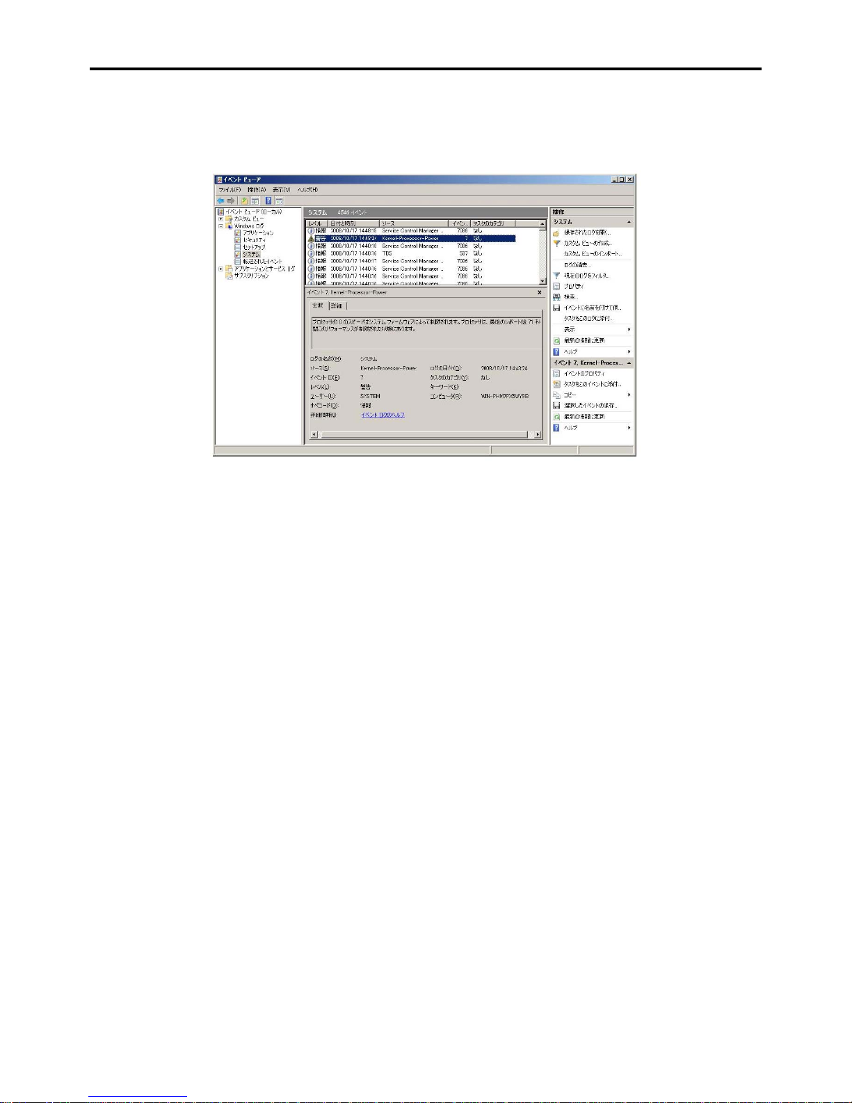
General Description 2-23
Notes on Using Windows Server 2008
The following event will be logged in Event Viewer if power control feature is used on Windows Server 2008. However, it is
not the problem in operating the system, the event is logged because the P-State is controlled by the server side.
Page 56

2-24 General Description
EXPRESSBUILDER
The DVD of this server's accessories contains a setup utility called "ExpressBuilder".
The major functions of the ExpressBuilder are:
To install the Operating System.
"Express Setup" helps you to install the Windows Operating System. (See Chapter 5)
To diagnose the server.
ExpressBuilder includes System Diagnostics to check this server. (See Chapter 7)
To create a driver disk.
Use this function to create "OEM-disk for Windows" used for a manual installation of Windows. (See Appendix D-F)
To update System BIOS
Use this function to update the server's system BIOS or firmware. (See Chapter 8)
To update Windows system*
"Update the system" in the Autorun menu (See Chapter 6) updates the several drivers of Windows on the server.
To install several management utilities*
ExpressBuilder includes the management utilities (NEC ESMPRO, Universal RAID utility and so on). You can
install the applications from ExpressBuilder.(See Chapter 6)
To read several documents*
You can refer to the documents from the Autorun menu. (See Chapter 6)
* These functions are available on Windows system.
NOTE: Some features among those listed above can be used from the remote computer via cross
cable (COM), or LAN. See Chapter 6 for details.
Page 57

General Description 2-25
NEC ESMPRO
The NEC ESMPRO is a server management software that runs on the OS. The NEC ESMPRO includes the NEC ESMPRO
Manager for the server monitoring terminal and the NEC ESMPRO Agent for the server.
NOTE: For details of major functions of the NEC ESMPRO, system configuration and setups
with the NEC ESMPRO, see Chapter 6.
Available functions of the NEC ESMPRO depend on the OS you install. Ask your service
representative for details.
Maintenance Tools
The Maintenance Tools is used for maintenance and fault analysis of the server. This tool is usually used by the service
representative.
See Chapter 8 for details.
SYSTEM DIAGNOSTIC UTILITY
The system diagnostic utility contained in the ExpressBuilder is useful to detect hardware failures. See Chapter 7 for details.
Page 58
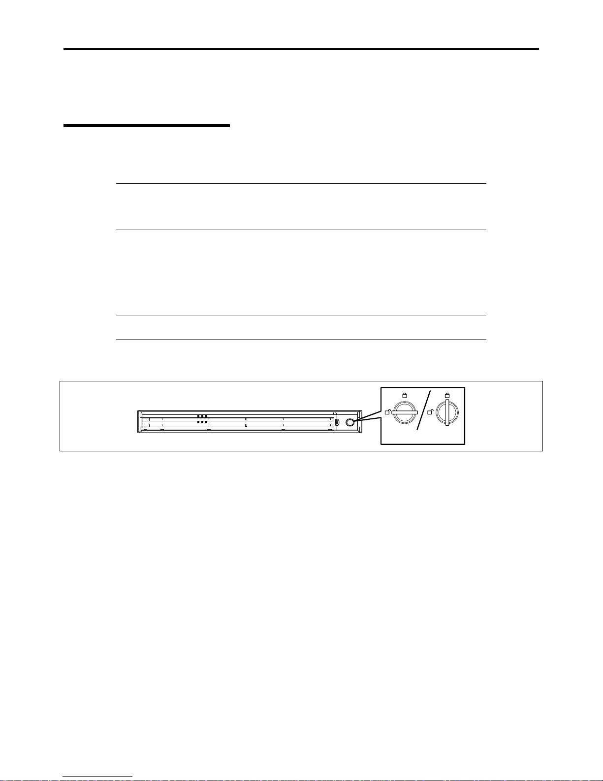
2-26 General Description
USING YOUR SERVER
This section describes basic operations of the server including how to use devices such as the optical disk drive.
Front Bezel
Remove the front bezel to power on/off the server, to access the optical disk drive and to install/remove hard disk drives to the
3.5-inch disk bays.
IMPORTANT:
To open the front door, you must unlock the door with the provided security key.
Pay attention not to press the POWER switch when you install or remove the front bezel.
Installing or Removing the Front Bezel
When turning the power of the server on/off, accessing to the optical disk drive, or installing or removing a hard disk drive on
or from the 3.5-inch disk bay, first remove the front bezel.
IMPORTANT: The front bezel can be opened only when you unlock it by using the attached
security key.
1. Insert the attached security key into the key slot and turn the key to the front bezel side with it pressed lightly to
release the lock.
Lock
Unlock
2. Hold the right end of the front bezel lightly to pull it toward you.
Page 59
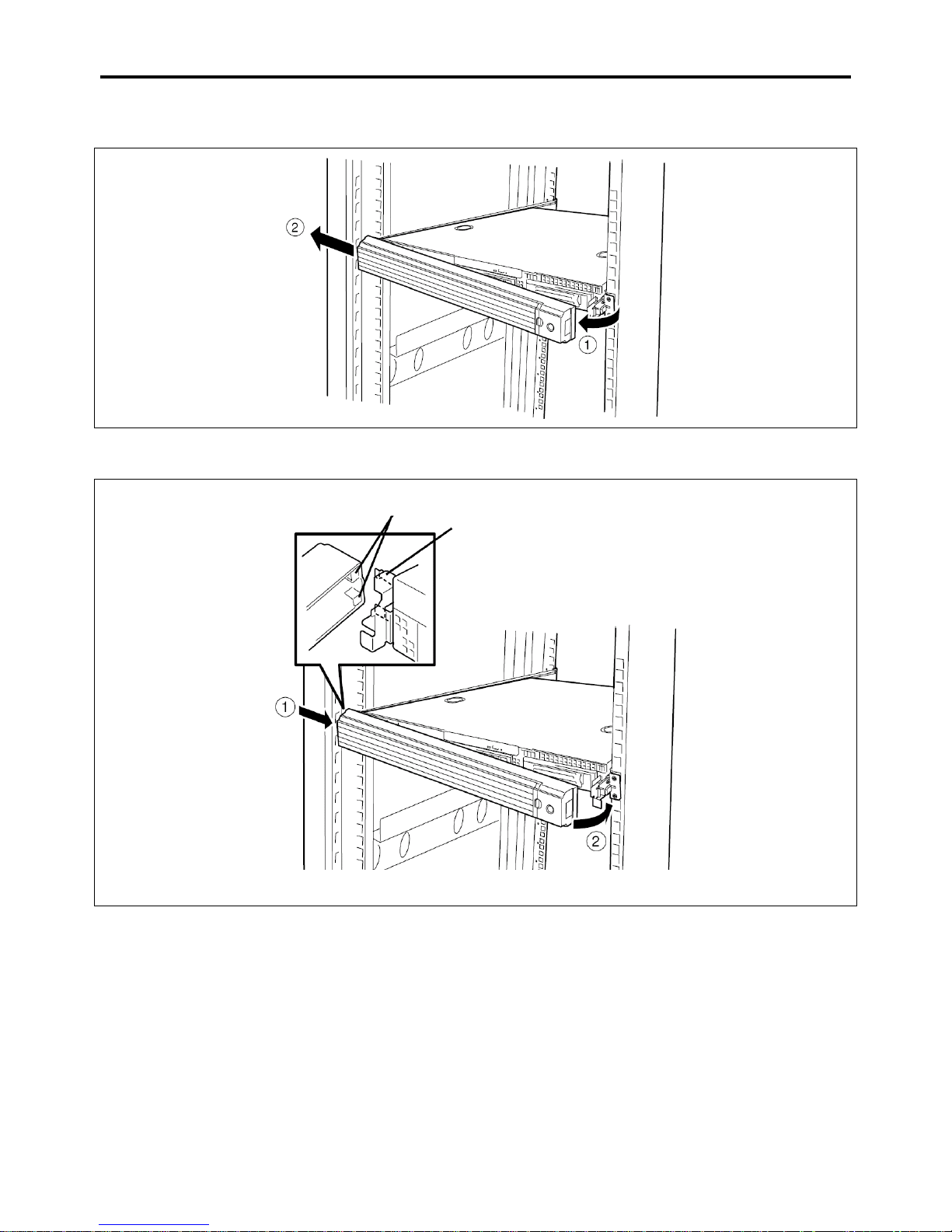
General Description 2-27
3. Slide the front bezel to the left a little to remove the tab from the frame and then remove the front bezel from the
server.
To install the front bezel, latch the tab at the left side of the front bezel on the server frame. After the installation, lock the front
bezel by using the key for security.
Tab
Frame
Page 60
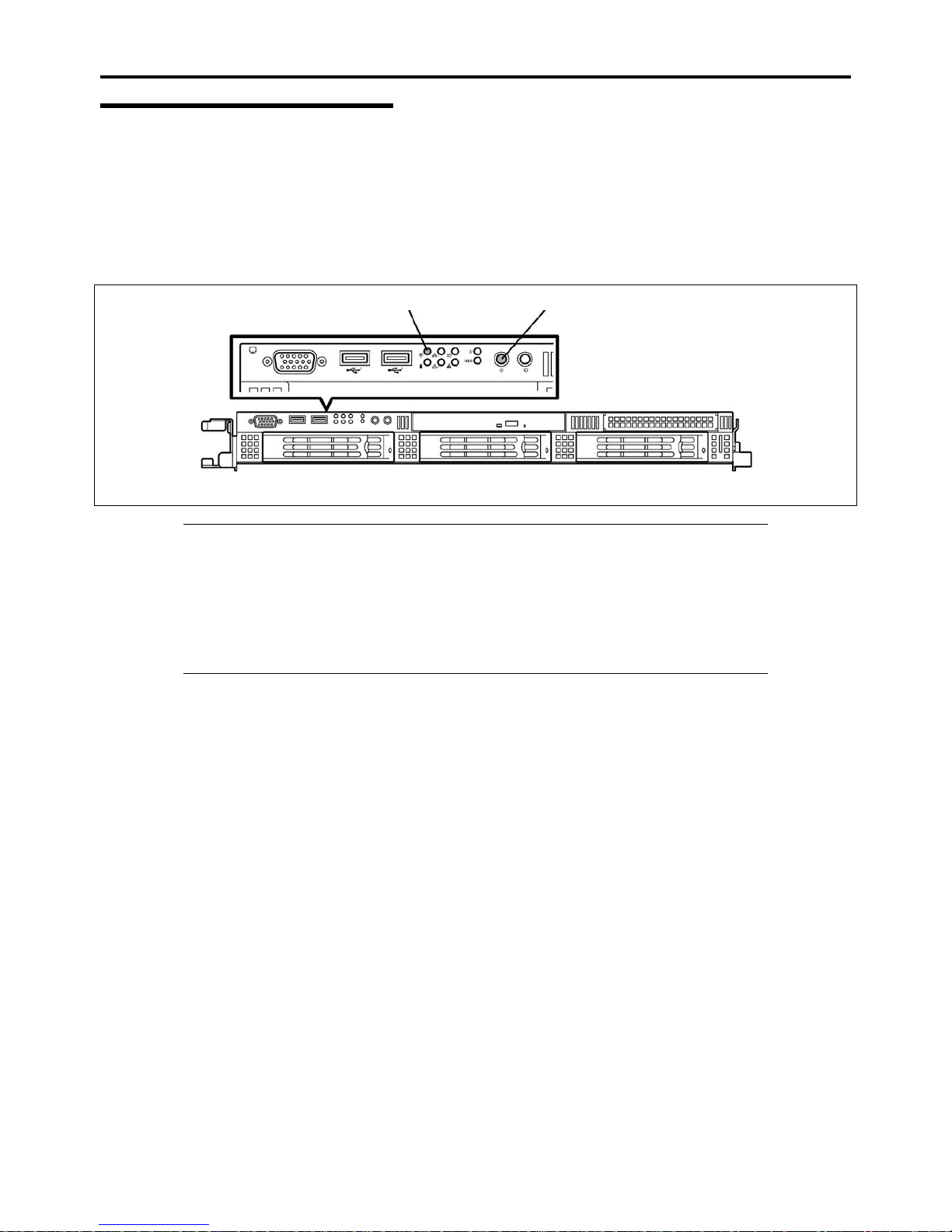
2-28 General Description
POWER Switch
Use the POWER switch to turn on/off the server.
Power On
Press the POWER switch on the front of the computer chassis.
The POWER LED lights in green.
POWER LED
POWER switch
IMPORTANT:
If the power cord is connected to a power control device such as a UPS (Uninterruptive Power
Supply), make sure that the power control device is powered.
If the power cord is connected to the server, an initial diagnosis of the hardware starts. The
POWER switch does not work while in diagnosis. Wait for about 30 seconds, then press the
POWER switch.
Always allow POST to complete before powering down your system.
Page 61
General Description 2-29
POST
POST (Power On Self-Test) is the self-diagnostic program stored in the system memory.
When you power on the server, the system automatically runs POST to check the mother board, ECC memory module, CPU
module, keyboard, and mouse. POST also displays messages of the BIOS setup utility, such as the start-up message, while in
progress.
With the factory setup of the server, the Bull logo appears on the display unit while POST is in progress. (To display the POST
check results, press Esc.)
NOTE: You can set the POST check results to appear on the display unit without pressing Esc.
To do so, select "Enabled" for "Boot-time Diagnostic Screen" under the Advanced menu of the
BIOS SETUP utility.
The POST check results should be checked in the following cases.
When the server is used for the first time.
When the server appears to fail.
When the server beeps for many times between power-on and OS start-up.
When an error message appears on the display unit.
Page 62
2-30 General Description
POST Execution Flow
The following describes the progress of POST in the chronological order.
IMPORTANT:
Do not make key entries or perform mouse operations while POST is in progress.
Some system configurations may display the message "Press Any Key" to prompt a key entry.
This message is driven by BIOS of an installed optional board. Make sure to read the manual
that comes with the optional board before any key entry.
Powering on the server, after you installed or removed an optional PCI board or moved it to
another slot, may display the message that indicates incorrect board configuration and suspend
POST.
In such a case, press F1 to continue POST. Board configuration can be made using the utility
described later.
1. After a few seconds from power-on, POST starts checking the memory. The count message of the basic and
expansion memory appears at top left on the display unit screen. The memory check may takes a few minutes to
complete depending on the memory size of the server. Also, it may take approximately one minute for the screen
display to appear after rebooting the server.
2. Some messages appear upon completion of the memory check. These messages appear to indicate that the system has
detected the CPU, baseboard management controller, keyboard, and mouse.
3. After a few seconds, POST displays the following message prompting you to launch the BIOS SETUP utility stored
in the system memory of the server. This message appears at bottom left on the screen.
Press <F2> to enter SETUP, <F12> to Network
Launch the BIOS setup utility when you need to change the settings to meet the requirements for the server. As long
as the above message is not displayed with an error message, you don't have to launch the utility. (Ignore the message.
POST will automatically proceed.)
To launch the SETUP utility, press F2 while the above message is displayed. See Chapter 4 for setup and parameters.
The server automatically restarts POST all over again when you exit the SETUP utility.
The message "<F12> to Network" prompts you network booting (PXE boot). If you press F12, the POST searches
for boot device on network.
Page 63
General Description 2-31
4. <When 3.5-inch disk model server contains 3.5-inch SATA hard disk drive>
If your server uses Onboard RAID Controller, the following message is displayed to prompt you to run RAID utility.
Press <Ctrl><M> to Run LSI SoftwareRAID Configuration Utility
Press Ctrl + M to run the utility. For detail explanation, see Chapter 4 for detail.
IMPORTANT: The LSI Software RAID Configuration Utility is used to manage the data stored
in hard disk drive, or for maintenance. See Chapter 4 for details. This feature is unavailable for
2.5-inch disk model.
5. If the POST detects the optional add-in card, it display the message prompting you to launch the add-in card BIOS
configuration utility. (Ignore the message. POST will automatically proceed a few seconds later.)
Refer to the manual that comes with the optional add-in card for detail.
6. If you set a password using the BIOS setup utility, SETUP, the password entry screen appears upon successful
completion of POST.
Up to three password entries will be accepted. Three incorrect password entries disable the server to boot. In such a
case, turn off the power and wait about 30 seconds before turning on to boot the server.
IMPORTANT: Do not set a password before installing an OS.
7. The OS starts when POST completes.
Page 64
2-32 General Description
POST Error Messages
When POST detects an error, it displays an error message on the display unit screen. See Chapter 8 for POST error codes.
IMPORTANT: Take a note on the messages displayed before consulting with your service
representative. Alarm messages are useful information for maintenance.
Power Off
Follow the procedure below to power off the server. If the power cord of the server is connected to a UPS, refer to the manual
that comes with the UPS or the manual for the application that controls the UPS.
IMPORTANT: Always allow POST to complete before turning off the server.
1. Shutdown the OS.
2. Press the POWER switch on the front of the server.
The POWER LED goes off.
3. Power off peripheral devices.
NOTE: The standby feature of Windows Server is not available. Do not select "Standby" in
Windows shutdown menu.
Page 65
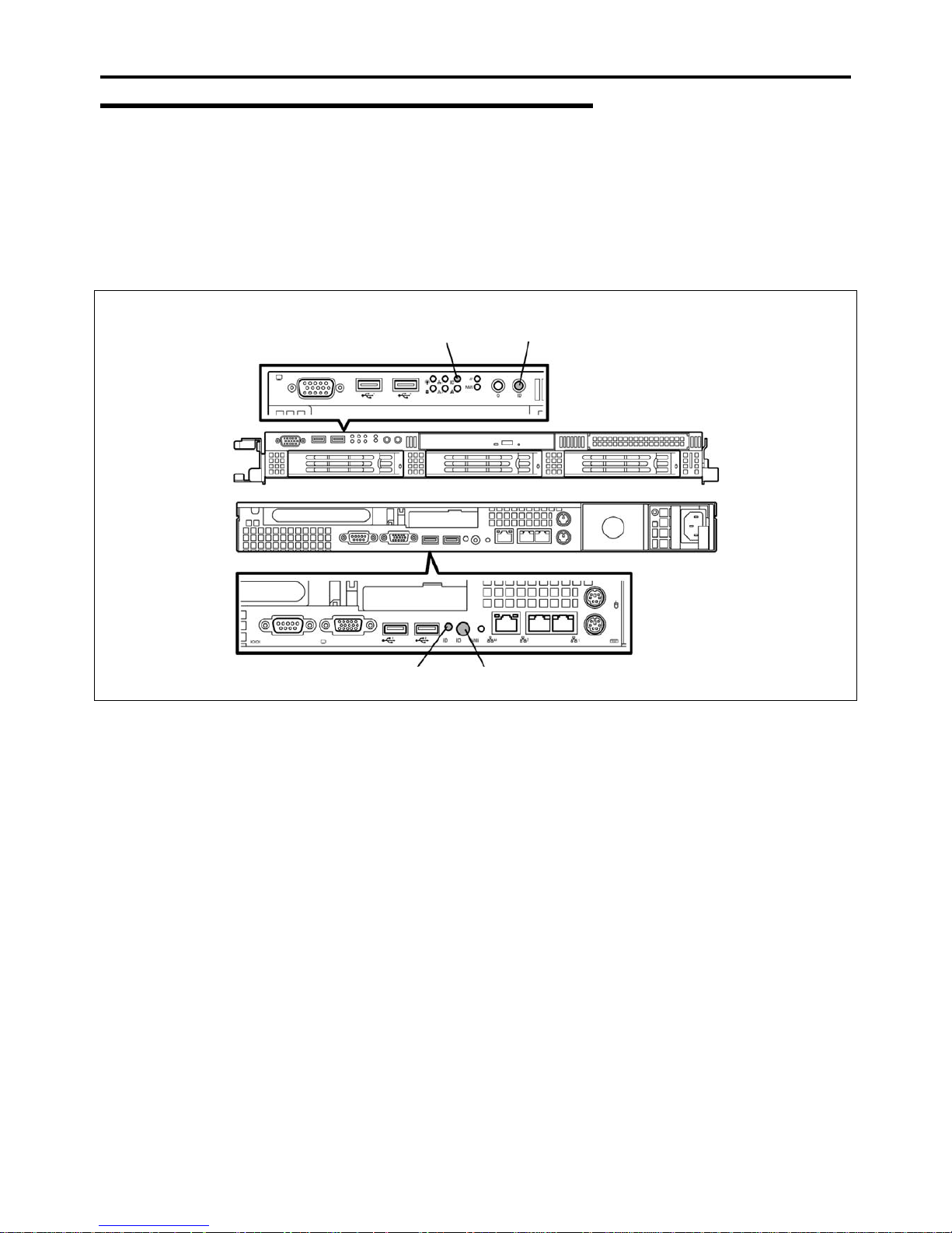
General Description 2-33
Identification of Servers ~ UID Switch ~
An "UID (Unit ID) LED" is provided on the front panel and rear panel. If more than one server is mounted in a single rack, the
LED identifies the server you are going to maintain.
The UID LED goes on when the UID (Unit ID) switch on the front panel is pressed. It goes off when the switch is pressed
again.
Maintenance from the rear of the rack may be carried out in a dark, narrow space. The interface cable of a server or power
supply unit in normal state may be disconnected by accident in this situation. To prevent this problem, you should start
maintenance after confirming the target server by using the UID switch.
UID switch
UID LED
UID LED
UID switch
Page 66
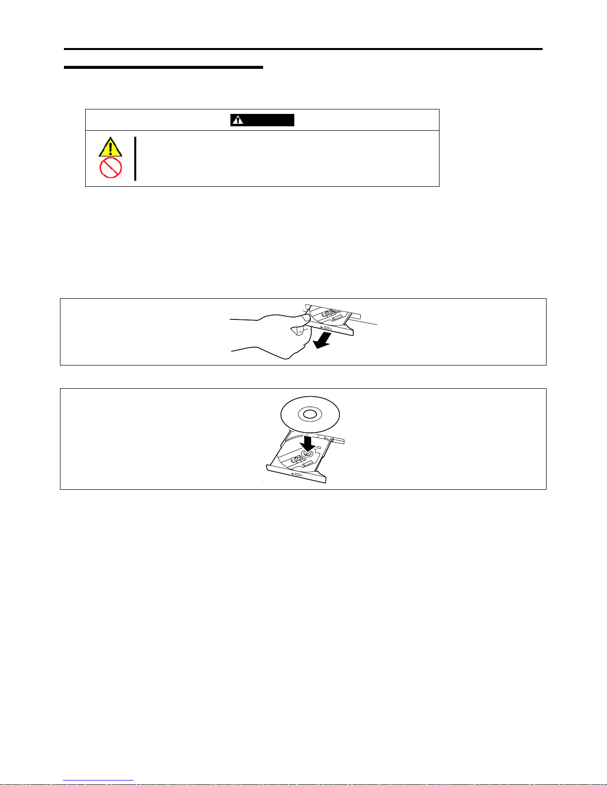
2-34 General Description
Optical Disk Drive
The server is provided with the optical disk drive on its front to read data from a disc.
CAUTION
Observe the following instructions to use the server safely. Failure to follow
these instructions may cause a fire, personal injury, or property damage. See
pages 1-3 to 1-12 for details.
Do not leave the tray ejected from the optical disk drive.
Set a disc on the optical disk drive in the following procedure.
1. Confirm that the power of the server is on (with the POWER LED being lit) before setting the disc on the optical
disk drive.
2. Press the Eject button on the front of the optical disk drive.
The tray comes out a little.
3. Hold the tray lightly and pull it out toward you until the tray stops.
4. Put the disc on the tray carefully and securely with the character printed surface facing upward.
Page 67
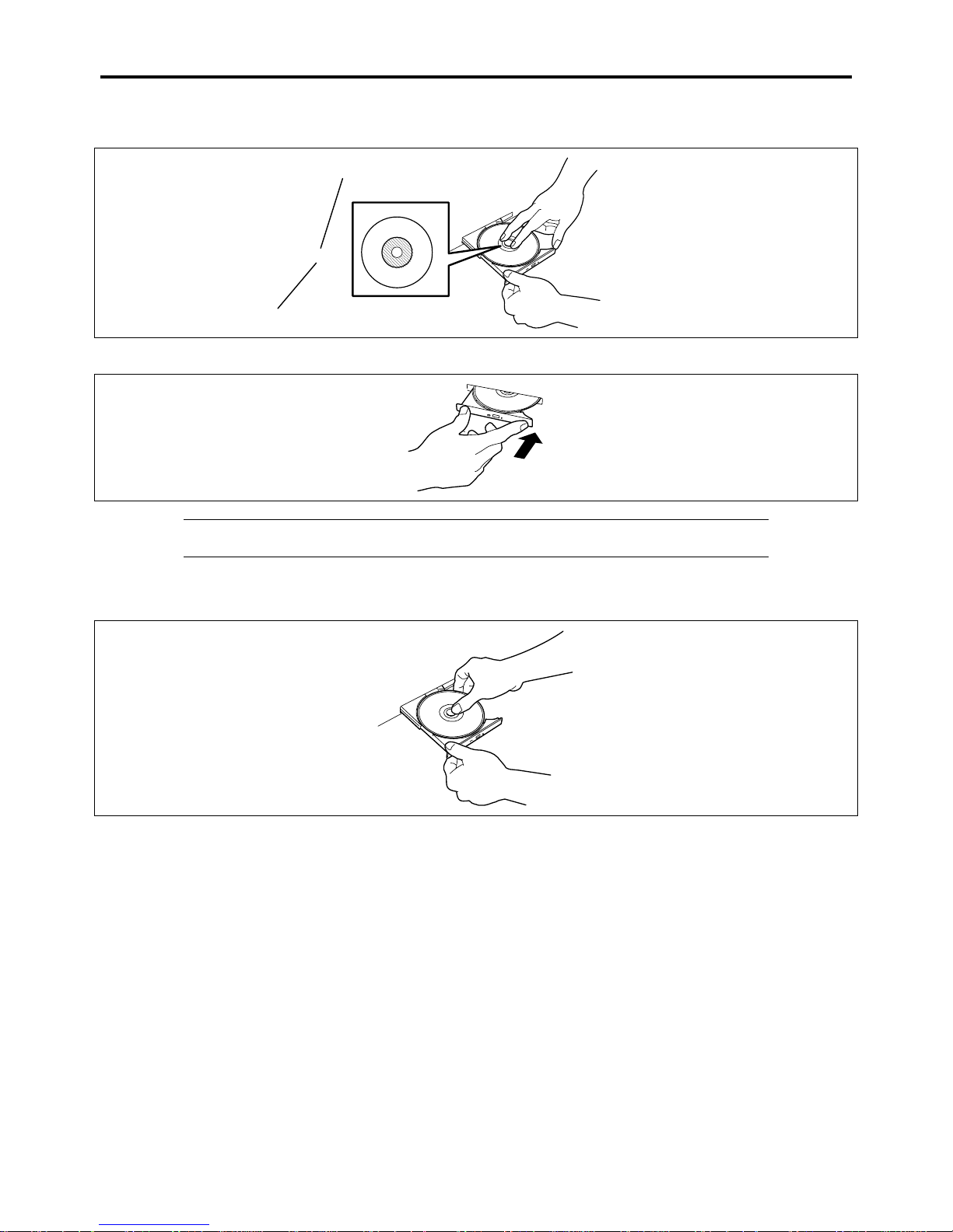
General Description 2-35
5. As shown in the figure below, hold the tray with a hand and press the disc with fingers of another hand to make the
hole of the disc fit to the rotor at the center of the tray.
Rotor
Press this part of disc.
6. Push the front of the tray lightly to retract it into the drive.
IMPORTANT: If a noisy sound in driving the optical disk drive occurs after setting a disc, set it
again correctly.
To take out the disc from the optical disk drive, press the Eject button in the similar way in setting the disc to make the tray go
out.
If the access LED is lit, the disc is being accessed. Confirm that the access LED is not lit before pressing the Eject button.
As shown in the figure below, hold the tray with a hand and take the end of the disc lightly by the fingers of another hand with
the suppression of the rotor at the center of the tray to remove the disc from the tray.
Page 68
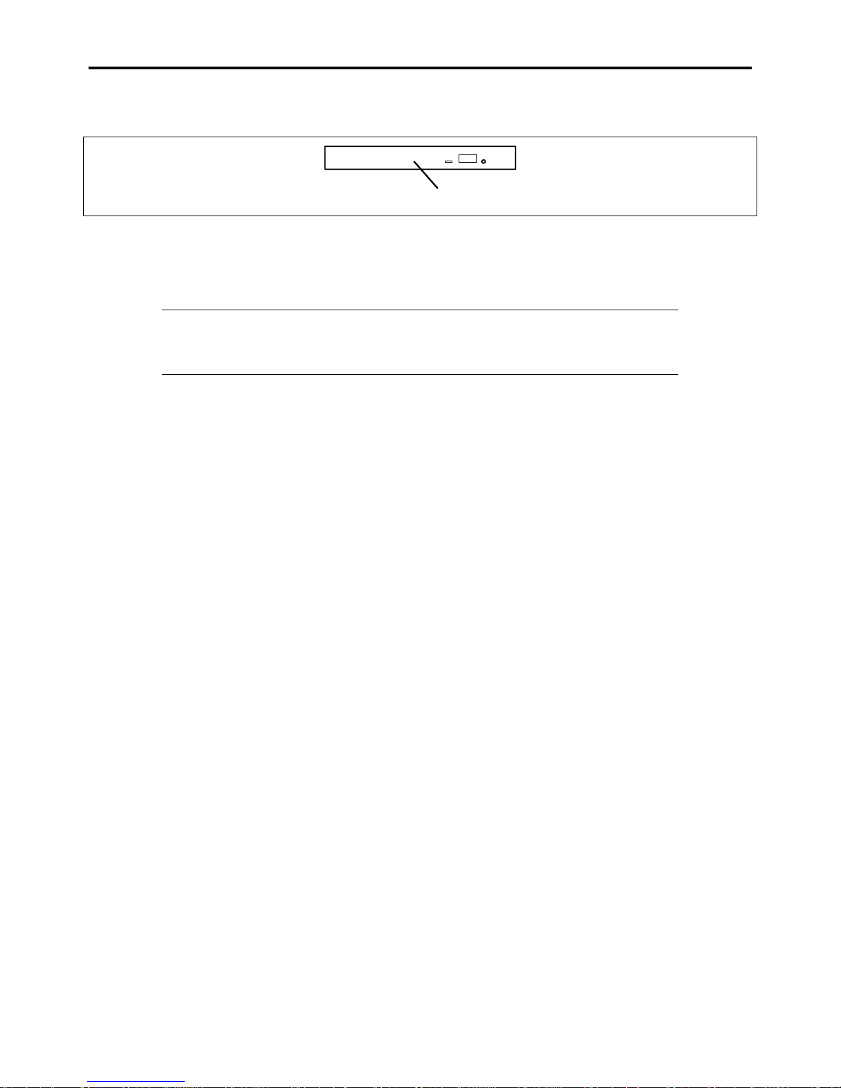
2-36 General Description
After taking out the disc, return the tray into the drive.
When you fail to eject the tray with the Eject button and take out the disc from the server, follow the procedure below.
Emergency hole
1. Press the POWER switch to power off the server. (The POWER LED goes off.)
2. Insert a metal pin of approximately 1.2 mm in diameter and 100 mm in length (a straightened large paper clip will
make a substitute) into the emergency hole on the right front of the optical disk drive and gently push it in until the
tray is ejected.
IMPORTANT:
Do not use a toothpick or plastic stick that is easy to break.
If the above procedure does not let you take out the disc, contact your service representative.
3. Hold the tray and pull it out.
4. Take out the disc.
5. Push the tray back into position.
Page 69
General Description 2-37
NOTE: Use of the Disc
Keep the following notes in mind to use the disc for the server:
For the disk which does not conform to the CD standard, the playback of such a disk with the
CD drive is not guaranteed.
Do not drop the disc.
Do not place anything on the disc or bend the disc.
Do not attach any label onto the disc.
Do not touch the signal side (nothing is printed on this side) with your hand.
Place the disc with its printed side upward and gently put it on the tray.
Do not scratch the disc or write anything directly on it with a pencil or ball-point pen.
Keep the disc away from cigarette smoke.
Do not leave the disc in a high-temperature place (e.g., place exposed to direct sunlight or close
to a heater).
When dust or fingerprints are attached on the disc, wipe the disc from its center to edge with a
dry soft cloth slowly and gently.
Use the CD cleaner to clean the disc. Do not use record spray/cleaner, benzene, or thinner.
Keep the disc in a disc case when not in use.
If the disc emits large noise in the optical disk drive, remove the disc and insert it back again.
Page 70

2-38 General Description
Page 71

Chapter 3
Setting Up Your Server
This chapter describes how to set up the server appropriate for your system, on a step-by-step basis.
Page 72
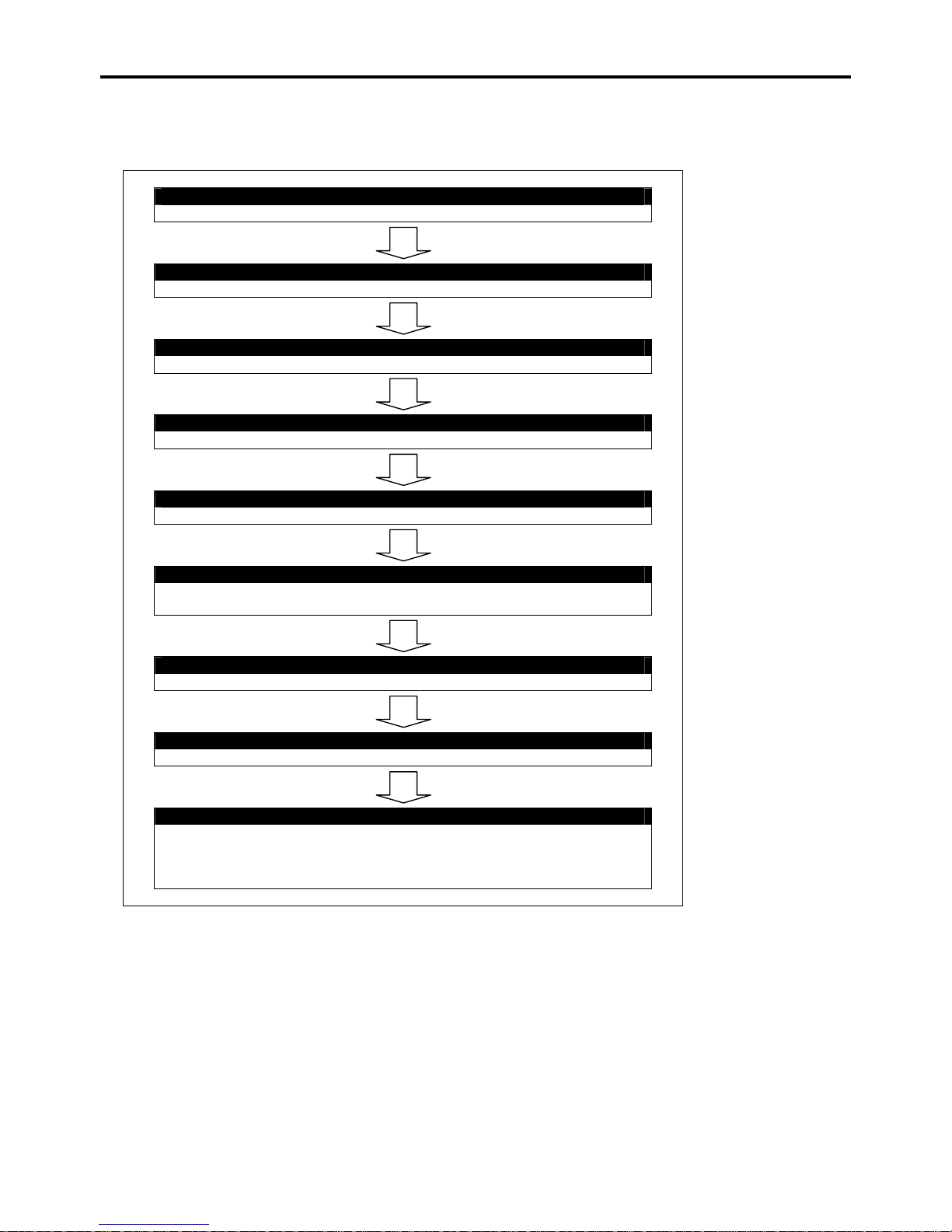
3-2 Setting Up Your Server
SETUP FLOW
Follow the flowchart below to set up the server.
Selecting the server site
Select a suitable site for the server and assemble the 19-inch rack assembly.
Unpacking the system
Unpack the server and accessories from the shipping carton box.
Install the server
Install the server into the rack assembly.
Connecting peripheral devices
Connect peripheral devices to the server.
Connecting the power cord
Connect the power cord to the server.
Turning on the server
Power on the server to start software setup. The process depends on the optional
internal devices installed and the peripheral devices connected.
Installing the operating system
Install an operating system to the server. See Chapter 5.
Installing the utilities
Install the utilities in the provided ExpressBuilder DVD. See Chapter 6.
Making backup copies of system information
After all the system setup procedures are completed, make backup copies of
system information.
System information is required for recovering the server from trouble or after
replacing the system board.
Page 73
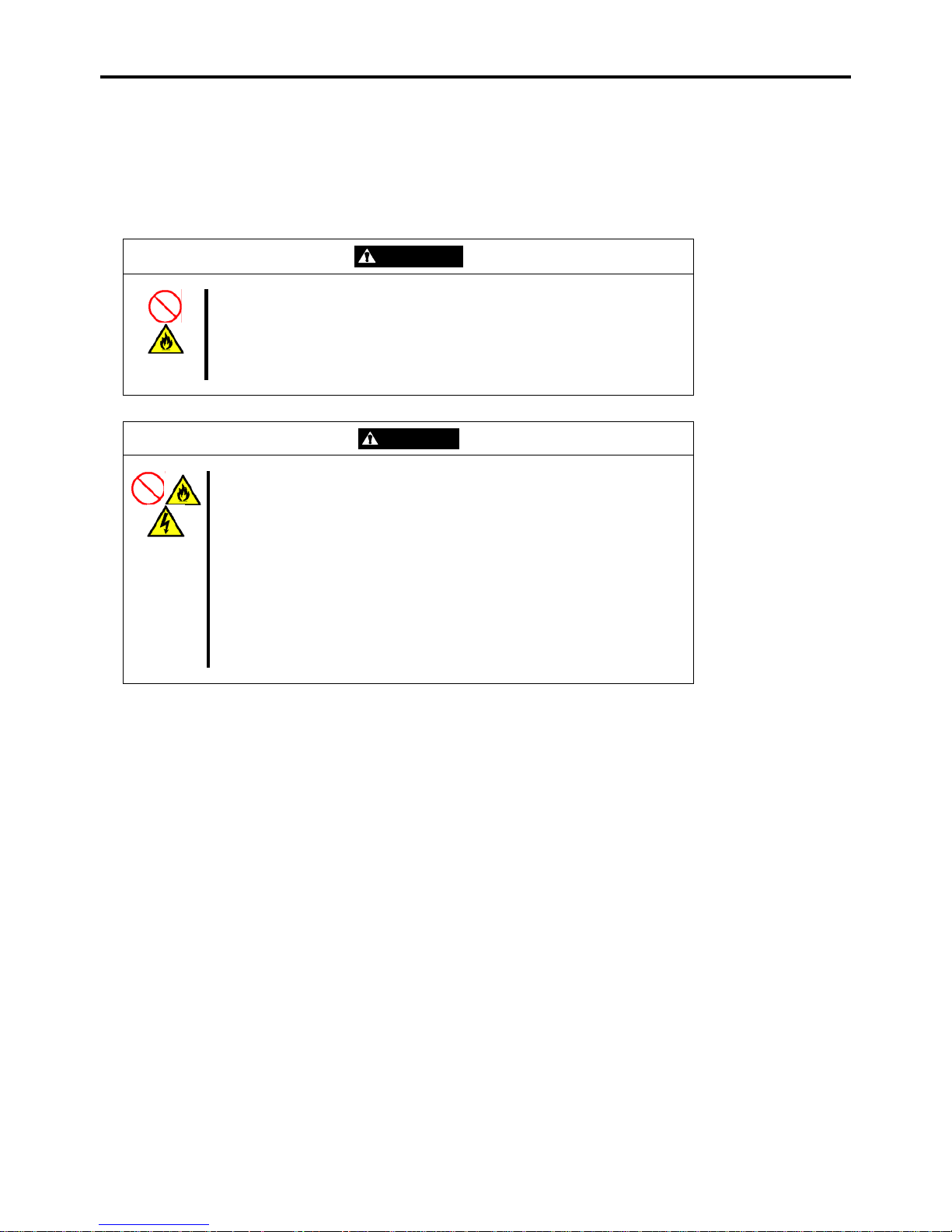
Setting Up Your Server 3-3
SELECTING SERVER SITE
To use the server, install it on a standard EIA 19-inch rack assembly.
Refer to the documentation attached to the rack or contact your service representative for the installation of the server in the
rack.
WARNING
Observe the following instructions to use the server safely. Failure to follow these
instructions may result in death or serious personal injury. See pages 1-3 to 1-12
for details.
Do not use the server in any unapproved place.
Do not connect the ground line to a gas pipe.
CAUTION
Observe the following instructions to use the server safely. Failure to follow
these instructions may cause a fire, personal injury, or property damage. See
pages 1-3 to 1-12 for details.
Do not carry or install the server only by a single person.
Do not install the server where the load may be concentrated on a specific
point.
Do not install any component on the server only by a single person.
Insert the hinge pins completely.
Do not pull out a device from the rack if the rack is unstable.
Do not leave more than one device being pulled out from the rack.
Do not provide the wiring exceeding the rating power.
Do not use the server in a place where corrosive gases exist.
Page 74

3-4 Setting Up Your Server
Do not install the rack in the places listed below. Installing the rack or mounting the server on the rack in such a place may
cause some malfunction to occur.
Narrow space from which devices cannot be pulled out from the rack completely
Place that cannot bear the total weights of the rack and devices mounted on the rack
Place where stabilizers cannot be installed or where the rack can be installed only after the practice of proper
earthquake-resistant construction
Place of uneven or slanting floor
Place of drastic temperature change (near a heater, air conditioner, or refrigerator)
Place where intense vibration may be generated
Place where corrosive gases (sulfur dioxide, hydrogen sulfide, nitrogen dioxide, chlorine, ammonia, ozone, etc) exist.
Place where the air (or dust) includes components accelerating corrosion (ex. sulfur, sodium chloride) or conductive
metals.
Place where chemicals may be accidentally sprayed over
Place where a carpet not subject to anti-static process is laid.
Place where some objects may be fallen on the rack
Place near a device generating intense magnetic field (such as a TV, radio, broadcast/communication antenna, power
transmission wire, and electromagnetic crane) is placed (If unavoidable, contact your service representative to
request proper shield construction.)
Place where the power cord of the server must be connected to an AC outlet that shares the outlet of another device
with large power consumption.
Place near equipment that generates power noise (e.g., contact spark at power-on/power-off of commercial power
supply through a relay). If you must install the server close to such equipment, request your service representative for
separate power cabling or noise filter installation.
IMPORTANT: Increase in temperature within rack and air flow
If more than one server are installed on the rack or the ventilation within the rack is not enough,
the temperature in the rack may be raised by the heat generated from the units to be higher than the
operation temperature of the server (10 to 35°C).
It causes the server to operate improperly. Review the air flow within the rack or in the room and
take sufficient measures so that the temperature within the rack does not exceed the warranted
temperature range during the system operation.
The server takes in the air from the front and exhausts it to the rear.
Page 75
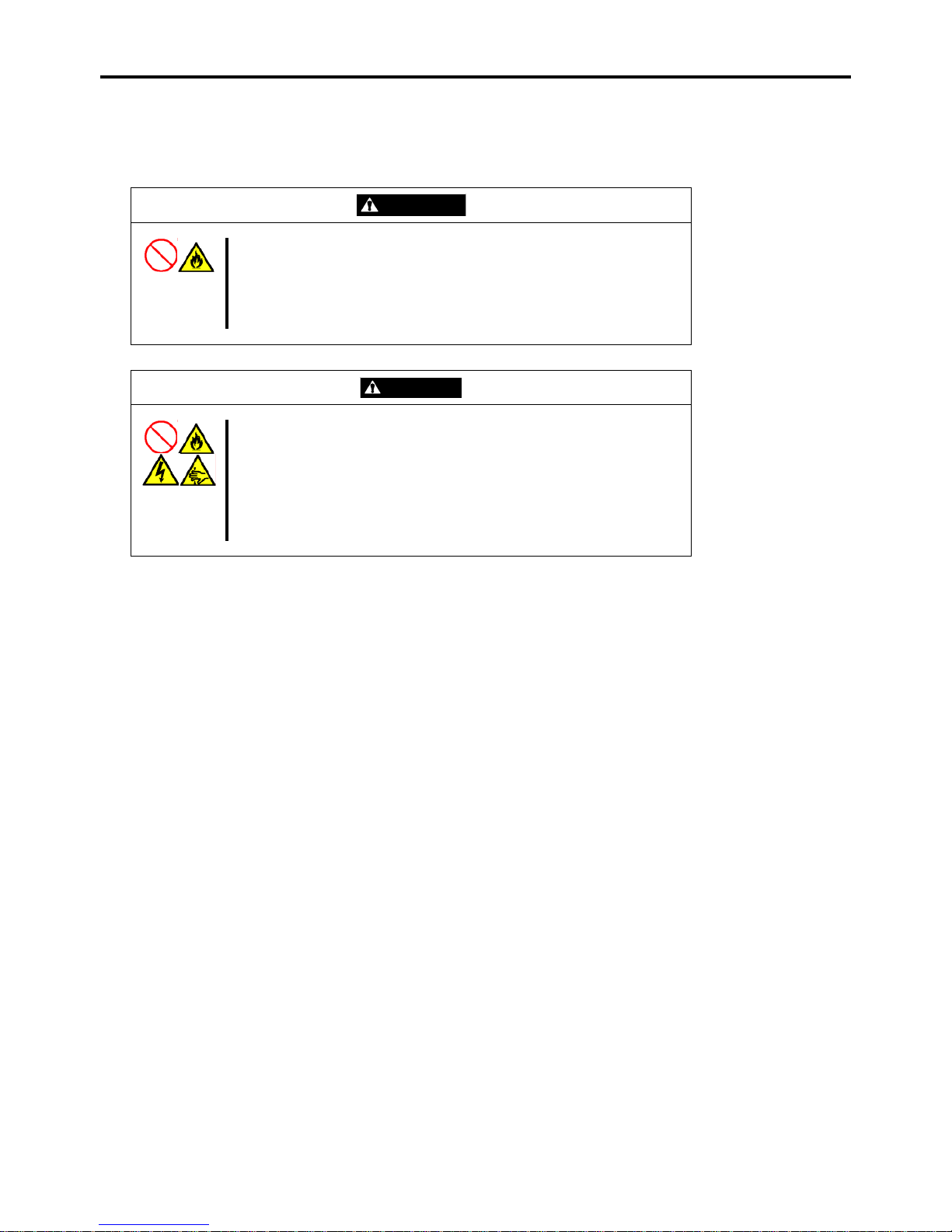
Setting Up Your Server 3-5
INSTALLING THE SERVER
This subsection provides the instructions for installing the server into a rack cabinet. (This subsection also describes the
removal procedures.)
WARNING
Observe the following instructions to use the server safely. Failure to follow
these instructions may result in death or serious personal injury. See pages
1-3 to 1-12 for details.
Do not use any rack which does not conform to the relevant standard.
Always use the server in the specified place.
CAUTION
Observe the following instructions to use the server safely. Failure to follow
these instructions may cause a fire, personal injury, or property damage.
See pages 1-3 to 1-12 for details.
Do not install/remove the server in/from the rack only by a single person.
Do not install the server on the rack leaving the cover removed.
Do not pinch your finger with mechanical components.
Do not apply any load on the server being pulled out from the rack.
Page 76

3-6 Setting Up Your Server
Installation
This server can be installed in either the Bull rack or a third vendor's rack. Take the following steps to install the server in the
rack.
Preparation for installation
When shipped from factory, the left and right slide rails are fixed with tapes at the front and side faces to prevent
from falling off during transportation. Peel off the tape before you install the server in the rack.
Tapes
Removing rail assemblies
1.
Remove the sliding rails from the left and right sides of the server.
Page 77
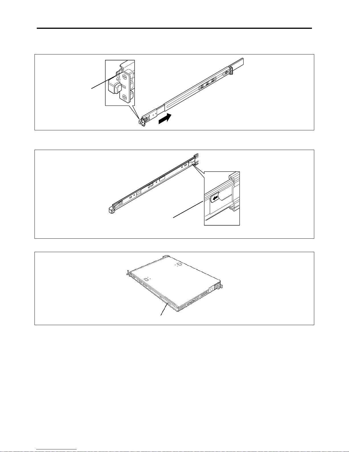
Setting Up Your Server 3-7
2. While pushing the unlock button on the front of the server, hold the rails and slowly move them toward the rear of
the server.
Press this button to
unlock the server.
3. When you hear a click, the rails are locked. Pull the release levers on the left and right sides of the server toward
direction indicated by an arrow (white) in the figure, and remove them from the server while unlocking it.
Pull the release lever toward the
direction shown by the arrow
(white) to remove the rail.
4. Only the inner rails remain screwed to the server when the rail assemblies have been removed.
Inner rail
Lever
Page 78
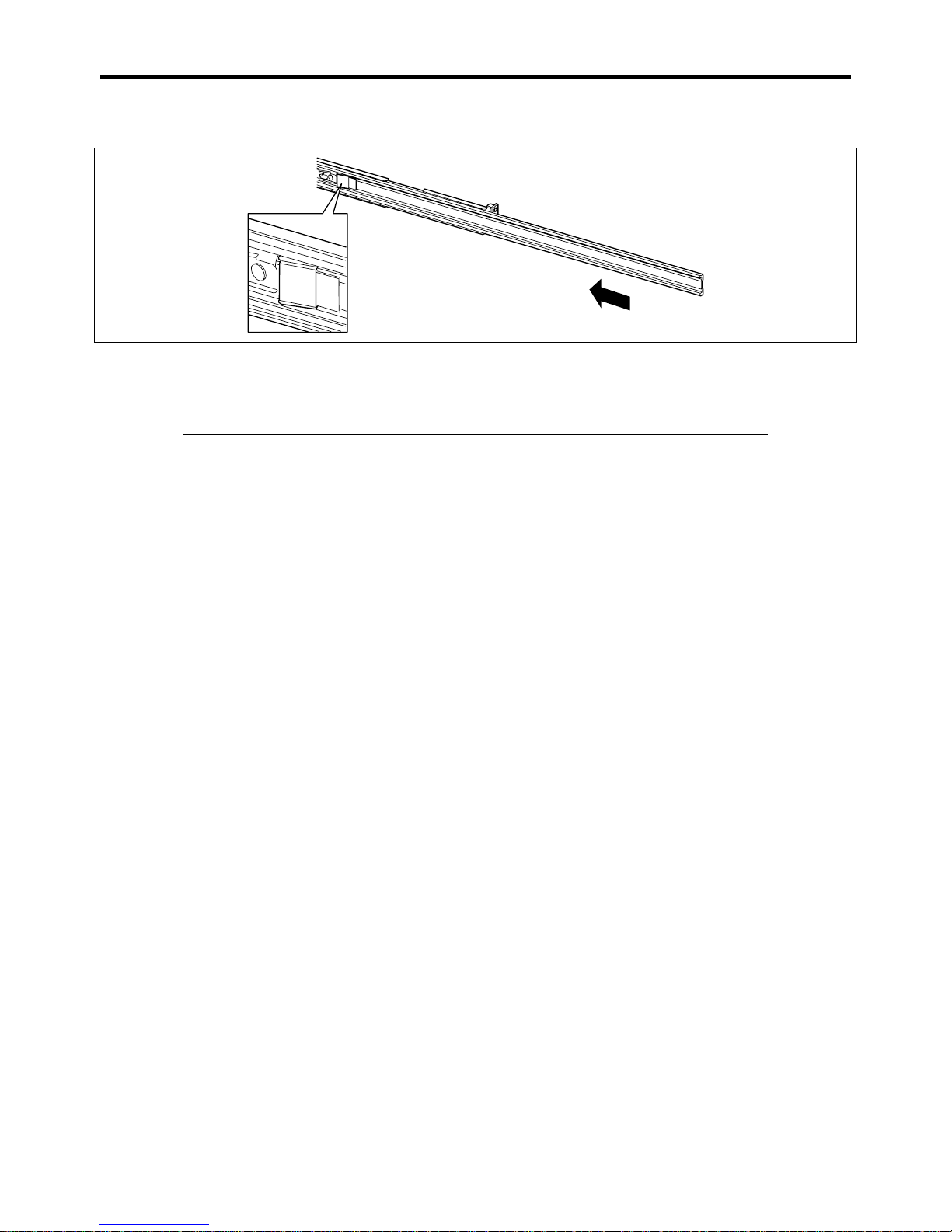
3-8 Setting Up Your Server
5. While pushing the levers, move the removed rail assemblies toward the direction indicated by an arrow in the figure,
to restore the original position.
IMPORTANT:
The removed rail assemblies are to be installed on the inner rails later.
Be very careful not to get your finger caught in the levers or rails.
Page 79
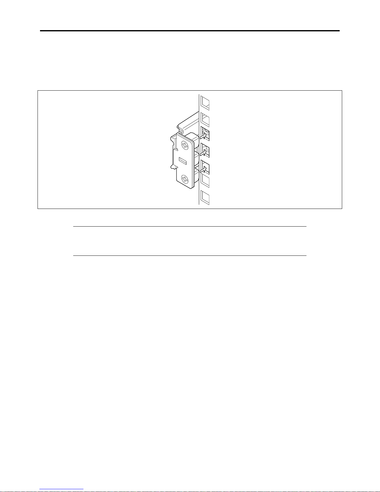
Setting Up Your Server 3-9
Installing Rail Assemblies
1.
Insert the square projection of the rail assembly into the angle hole on the 19-inch rack until you hear a click : the rail
assembly is locked.
The figure below shows the right side (front) of the rack. Install the rail assemblies to the right side (rear), and left
side (front and rear) of the rack using the same procedure.
Make sure that the rail assembly is installed at the same level as the other slide rail assembly already installed.
NOTES:
There may be some backlashes in the front and rear, however, it is not a deficiency.
Make sure that the rail assembly is surely locked to the rack.
Page 80
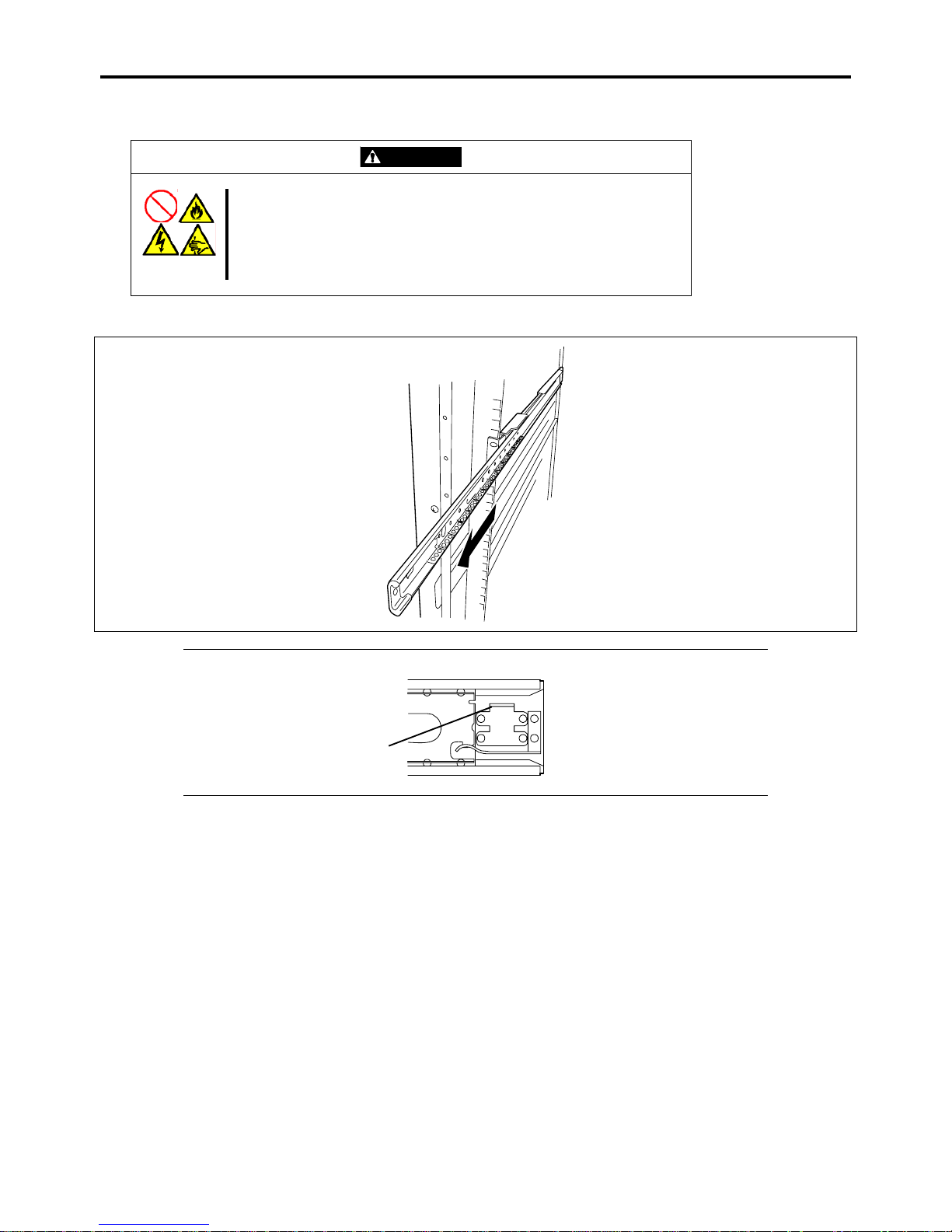
3-10 Setting Up Your Server
Installing the Server
CAUTION
Observe the following instructions to use the server safely. Failure to follow
these instructions may cause a fire, personal injury, or property damage.
See pages 1-3 to 1-12 for details.
Do not lift the server only by a single person.
Do not pinch your finger with mechanical components.
1. Pull out the sliding rails of the right and left rail assemblies until they are locked.
NOTE: Make sure that the sliding rails are surely locked by the stopper.
Stopper
Page 81
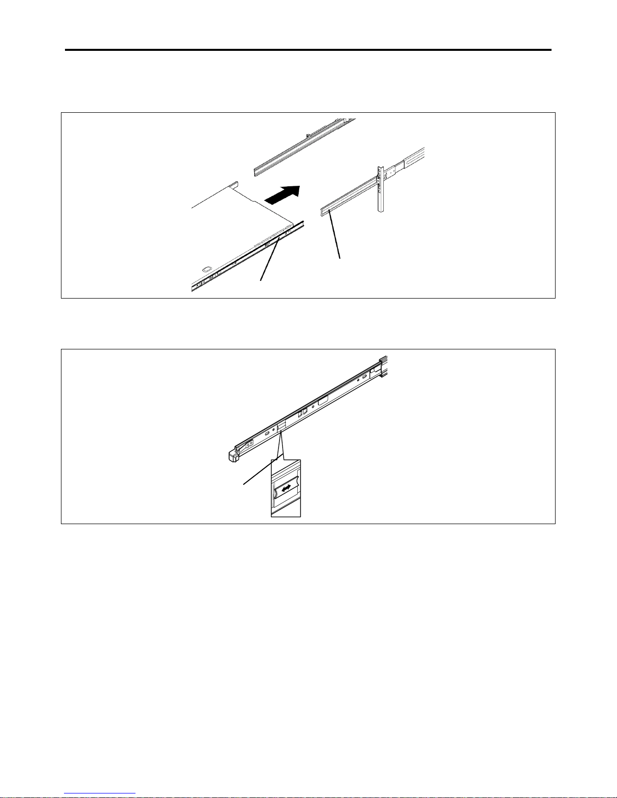
Setting Up Your Server 3-11
2. At least two persons are required to install the server. Securely hold the server and install it in the rack.
Firmly fit the inner rails on the sides of the server into the rail assemblies that are installed on the rack, and then
slowly push the server into the rack.
Rail assembly
Inner rail at server side
3. If the server is locked on its way into the rack, slowly push it in while pressing the release levers (blue) on the right
and left sides of the server.
When the server is completely pushed into the rack, the server is locked.
Release lever (blue)
Page 82
3-12 Setting Up Your Server
IMPORTANT:
Be very careful not to get your finger caught in the levers or rails.
Insert both sides of inner rails straight into the rack.
Hold the thumbscrews on both sides of the server, and install the server carefully while making
sure the installation position.
NOTES:
At the first installation, you may feel strong friction in pushing because the mechanical
components cannot be completely engaged with each other. Push the server intensely.
If the installation is incomplete, either of rails may not go further on its way. In such a case,
pull out the server completely until it is locked. Then, push the server in while unlocking the
right and left sides of it.
4. Make sure that the sliding rails move smoothly by pulling the server out of the rack and pushing it in several times.
NOTES:
When installing the server in the location adjacent to other devices, pay attention to
interference. If the server disturbs the devices already installed, adjust the position, and install
the rail assembly again.
Make sure that the sliding rails move smoothly. If the sliding rails are stuck to the rack frame
and do not come out, reinstall them.
Page 83
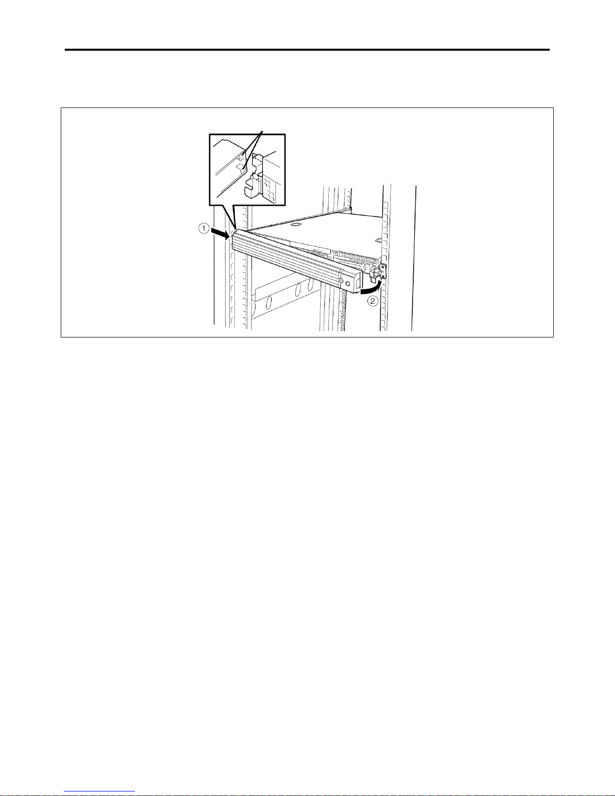
Setting Up Your Server 3-13
Installing the Front Bezel
1.
Install the front bezel so that the left tab on the front bezel engages with the chassis frame.
Tabs
Page 84
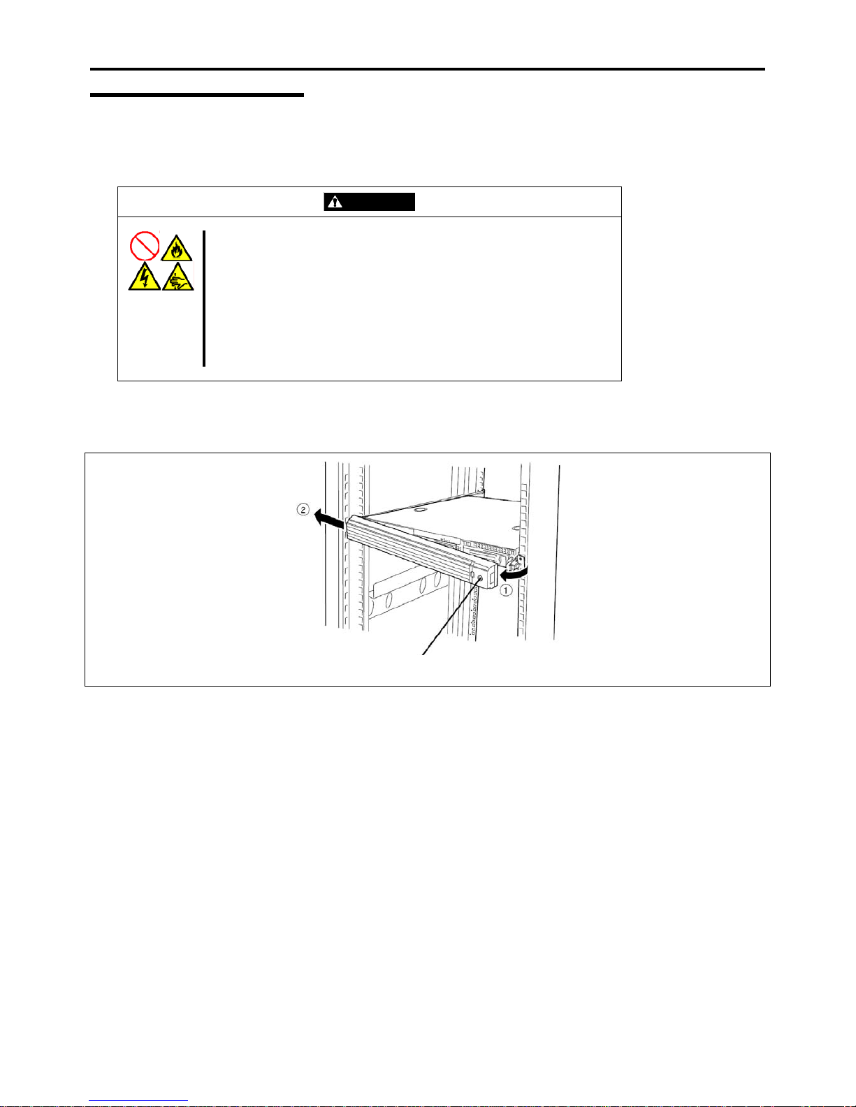
3-14 Setting Up Your Server
Removal
Removing the Server
Remove the server from the rack using the following procedure.
CAUTION
Observe the following instructions to use the server safely. Failure to follow
these instructions may cause a fire, personal injury, or property damage. See
pages 1-3 to 1-12 for details.
Do not install/remove the server in/from the rack only by a single person.
Do not pinch your finger with mechanical components.
Do not apply any load on the server being pulled out from the rack.
Do not pull out a device from the rack if the rack is unstable.
Do not leave more than one device being pulled out from the rack.
Do not pull out the server from the rack while it is operating.
1. Make sure that the server is powered off, and disconnect the power cords and all the interface cables from the server.
2. Unlock the front bezel with the security key.
Security key slot
3. <This step is required only when the optional cable arm is mounted.>
Remove the cable arm from the server.
Page 85
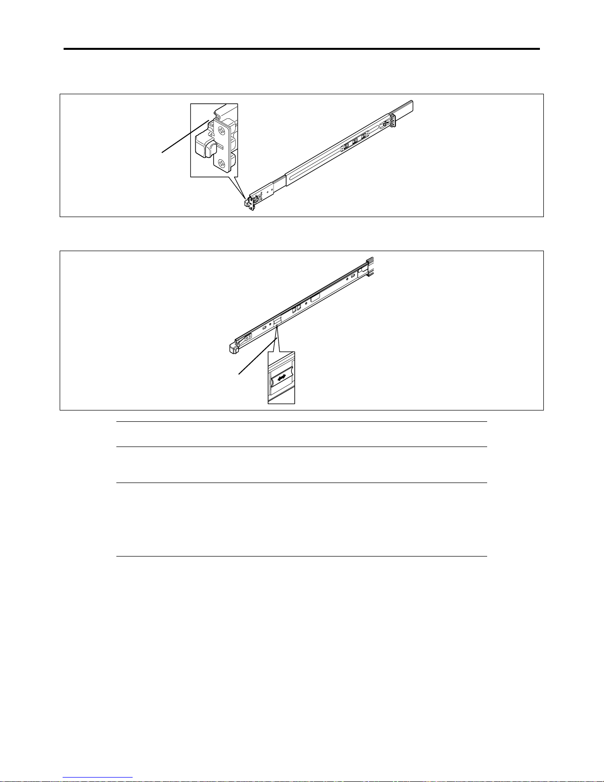
Setting Up Your Server 3-15
4. While pushing the left and the right unlock buttons on the front of the server, pull out the server from the rack slowly
and carefully.
Press this button to
unlock the server.
5. While pushing the right and left release levers (blue) forward or rearward to unlock, slowly pull out the server from
the rack.
Release lever (blue)
IMPORTANT: Do not apply any load on the server pulled out from the rack. Doing so may
cause personal injury if the server drops.
6. Firmly hold the server, and take it out from the rack.
IMPORTANT:
Pull out the server slowly holding the bottom of the server by at least two persons.
Do not apply any load on the server pulled out from the rack. Doing so may cause personal
injury if the server drops.
Be very careful not to get your finger caught in the levers or rails.
Page 86
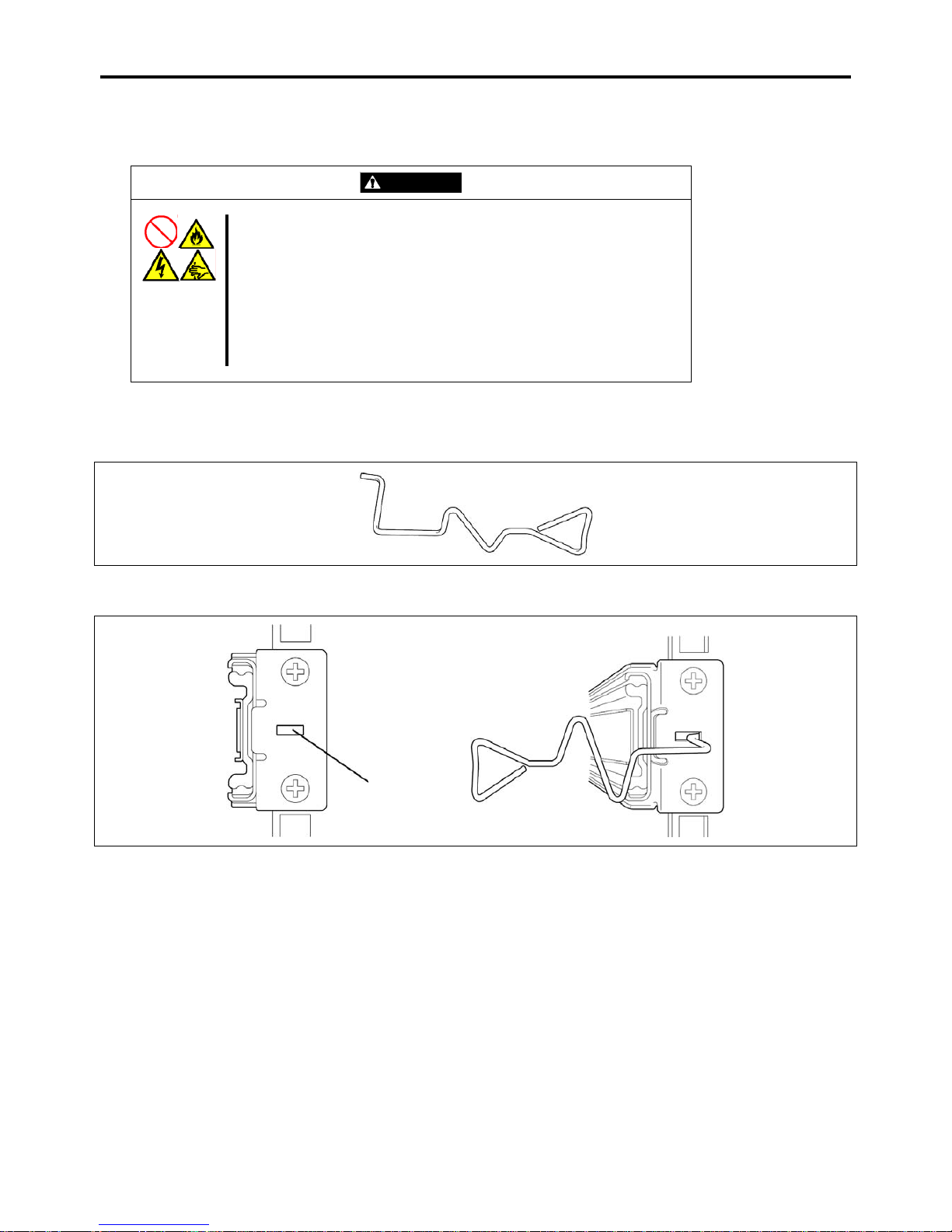
3-16 Setting Up Your Server
Removing Rail Assemblies
Remove the rail assembly from the 19-inch rack using the following procedure.
CAUTION
Observe the following instructions to use the server safely. Failure to follow
these instructions may cause a fire, personal injury, or property damage. See
pages 1-3 to 1-12 for details.
Do not install/remove the server in/from the rack only by a single person.
Do not pinch your finger with mechanical components.
Do not apply any load on the server being pulled out from the rack.
Do not pull out a device from the rack if the rack is unstable.
Do not leave more than one device being pulled out from the rack.
Do not pull out the server from the rack while it is operating.
1. Remove the server from the rack according to "Removing the Server" described earlier.
2. Prepare the tool to remove the sliding rail (outer rail). The tool is provided with your server.
3. Insert the tool into the angle hole at the front of rail assembly, as shown in the figure below.
Angle hole
Page 87
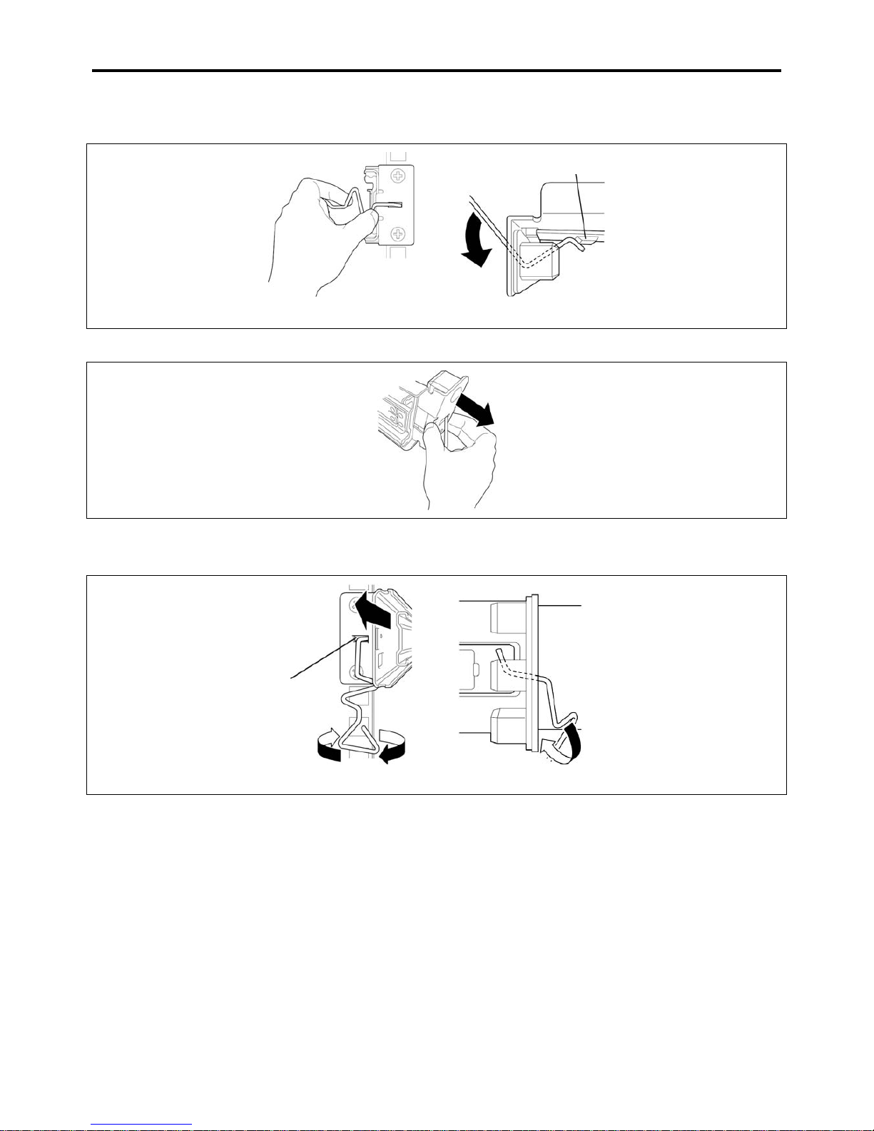
Setting Up Your Server 3-17
4. Unlock the rail assembly.
Unlock the rail assembly by applying force to the tool in the direction shown by an arrow.
Locking spring
Viewed from top
Viewed from front
5. While the rail assembly is being unlocked, remove it from the rack.
6. Insert the tool into the angle hole at the rear of rail assembly to unlock it.
Rotate the tool as shown in the figure below to unlock the rail assembly.
Angle hole
Viewed from front Viewed from side
7. While the rail assembly is being unlocked, remove it from the rack.
Page 88
3-18 Setting Up Your Server
CONNECTING PERIPHERAL DEVICES
Connect peripheral devices to the server. The server is provided with connectors for wide variety of peripheral devices on its
front and rear. The figure on the next page illustrates available peripheral devices for the server in the standard configuration
and locations of the connectors for the devices.
CAUTION
Observe the following instructions to use the server safely. Failure to follow these
instructions may cause a fire, personal injury, or property damage. See pages
1-3 to 1-12 for details.
Do not connect any interface cable with the power cord of the Bull
Server plugged to a power source.
Do not use any unauthorized interface cable.
IMPORTANT:
Power off the server and a peripheral device before connection. Connecting a powered
peripheral device to the powered server will cause malfunctions and failures.
To connect a third-party peripheral device or interface cable to the server, consult your service
representative for availability of such a device or cable. Some third-party devices may not be
used for the server.
A leased line cannot be connected directly to the serial port connectors.
Secure the power cord(s) and interface cables with a tie wrap.
Form the cables in such a way that they will not come into contact with the door or the guide
rails on the sides of the server.
Do not apply any pressure to the plug of the power cord.
Page 89
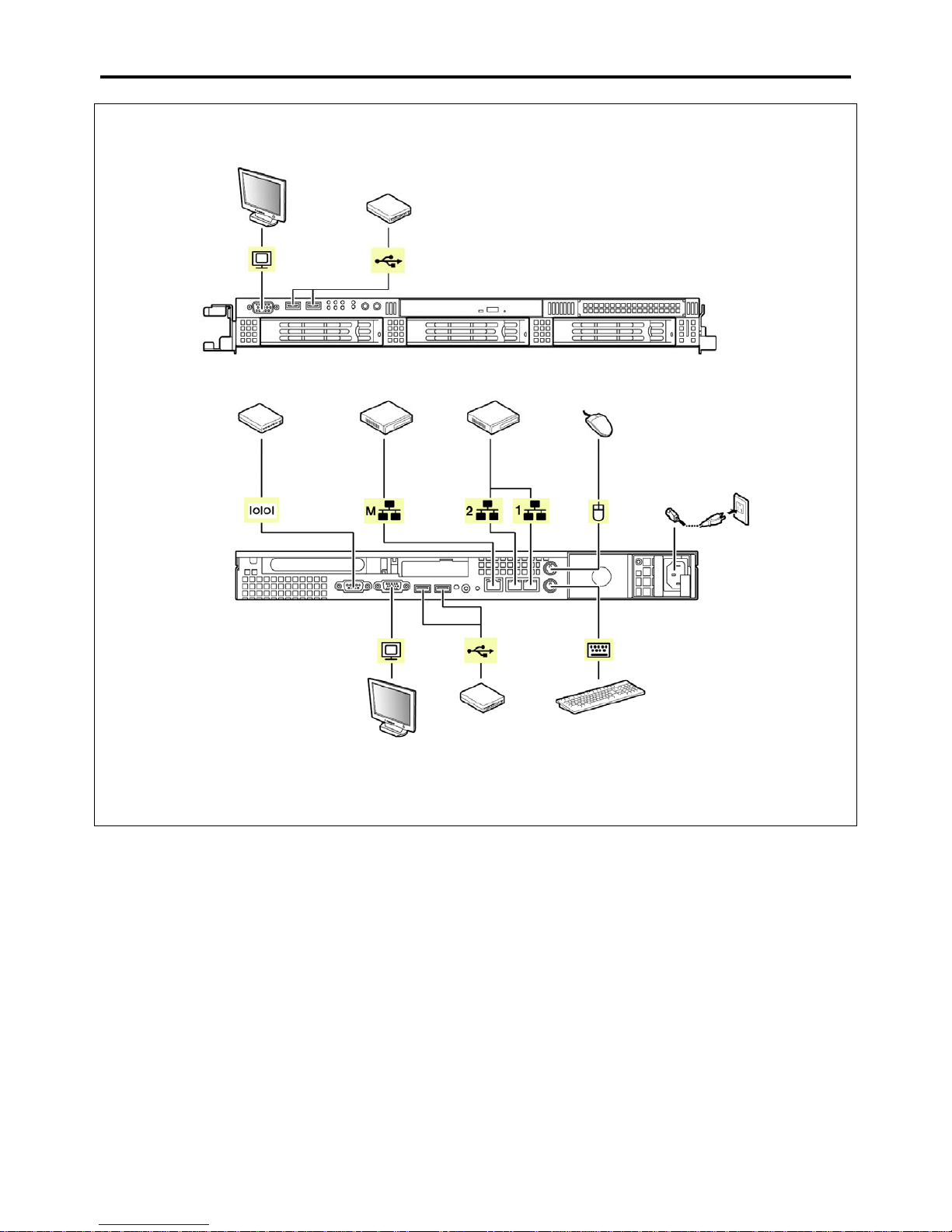
Setting Up Your Server 3-19
Display unit
*2
USB device
FRONT
Hub / switching hub
Device with the
serial interface
Mouse
100BASE-T/
1000BASE-TX/
-
Finally connect the provided
power cord to the receptacle.
*1
1000BASE-TX/
10BASE-T
If connecting the server to UPS,
see the explanation below.
REAR
USB device Keyboard
Display unit
*2
*1 Connect the power cord to a circuit breaker of 15 A or less.
*2 The display unit can be connected to either of front or rear port.
Page 90
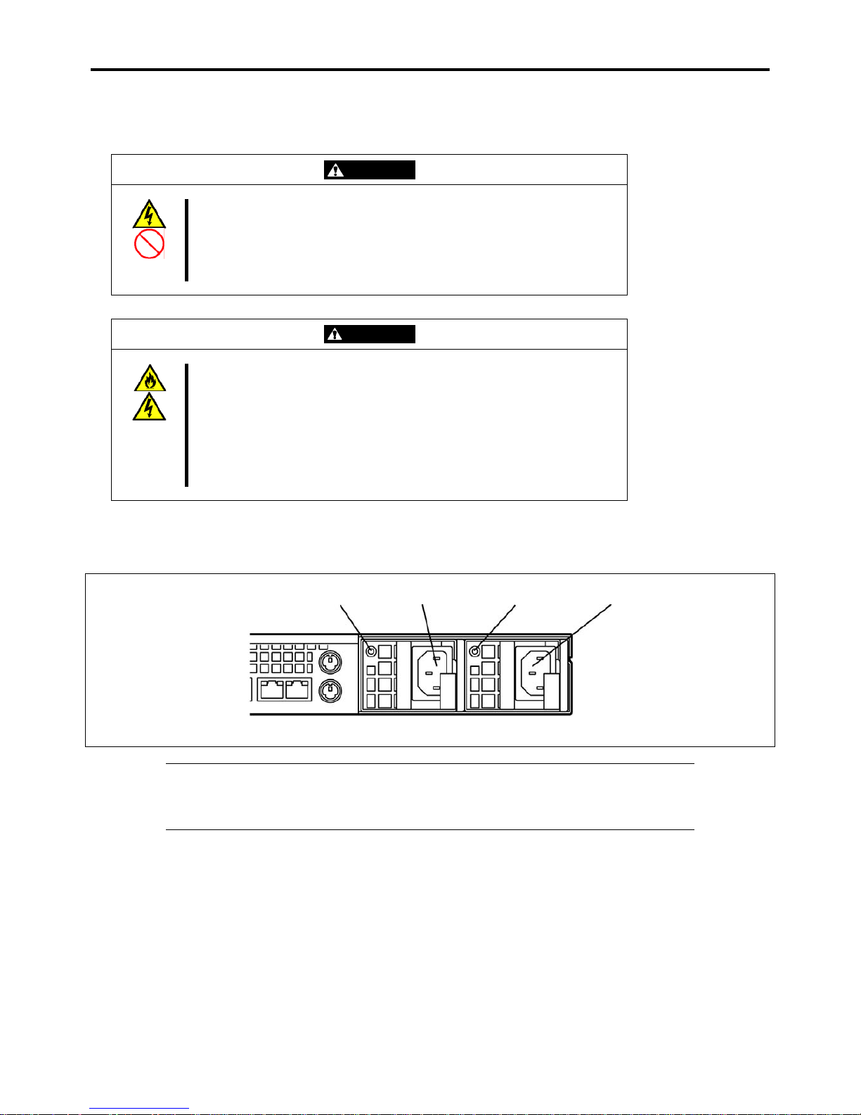
3-20 Setting Up Your Server
CONNECTING THE POWER CORD
Connect the provided power cord to the server.
WARNING
Observe the following instructions to use the server safely. Failure to follow these
instructions may result in death or serious personal injury. See pages 1-3 to 1-12
for details.
Do not hold the power plug with a wet hand.
Do not connect the ground wire to a gas pipe.
CAUTION
Observe the following instructions to use the server safely. Failure to follow these
instructions may cause a fire, personal injury, or property damage. See pages
1-3 to 1-12 for details.
Do not plug the power cord in to an improper power source.
Do not connect the power cord to an outlet that has an illegal number of
connections.
Insert the power plug into the outlet as far as it goes.
Use the authorized power cord only.
1. Plug the provided power cord into the power receptacle on the rear of the server.
2. Plug the other end of the power cord into the wall outlet.
AC inlet
AC POWER
LED
AC POWER
LED
AC inlet
IMPORTANT:
Connect the power cord to a circuit breaker of 15A or less.
Secure the power cord with a tie wrap.
Page 91

Setting Up Your Server 3-21
To connect the power cord from the server to an uninterruptive power supply (UPS), use service outlets on the rear of the UPS.
Refer to the manual that comes with the UPS.
When the power cord from the server is connected to a UPS, change the BIOS setup of the server to link with power supply
from the UPS.
To power on the server from the UPS (Uninterruptible Power Supply), select [Server] - [AC-LINK] - [Power On].
Change a parameter for "AC-LINK" under the Server menu of the BIOS SETUP utility. See Chapter 4 for details.
Page 92
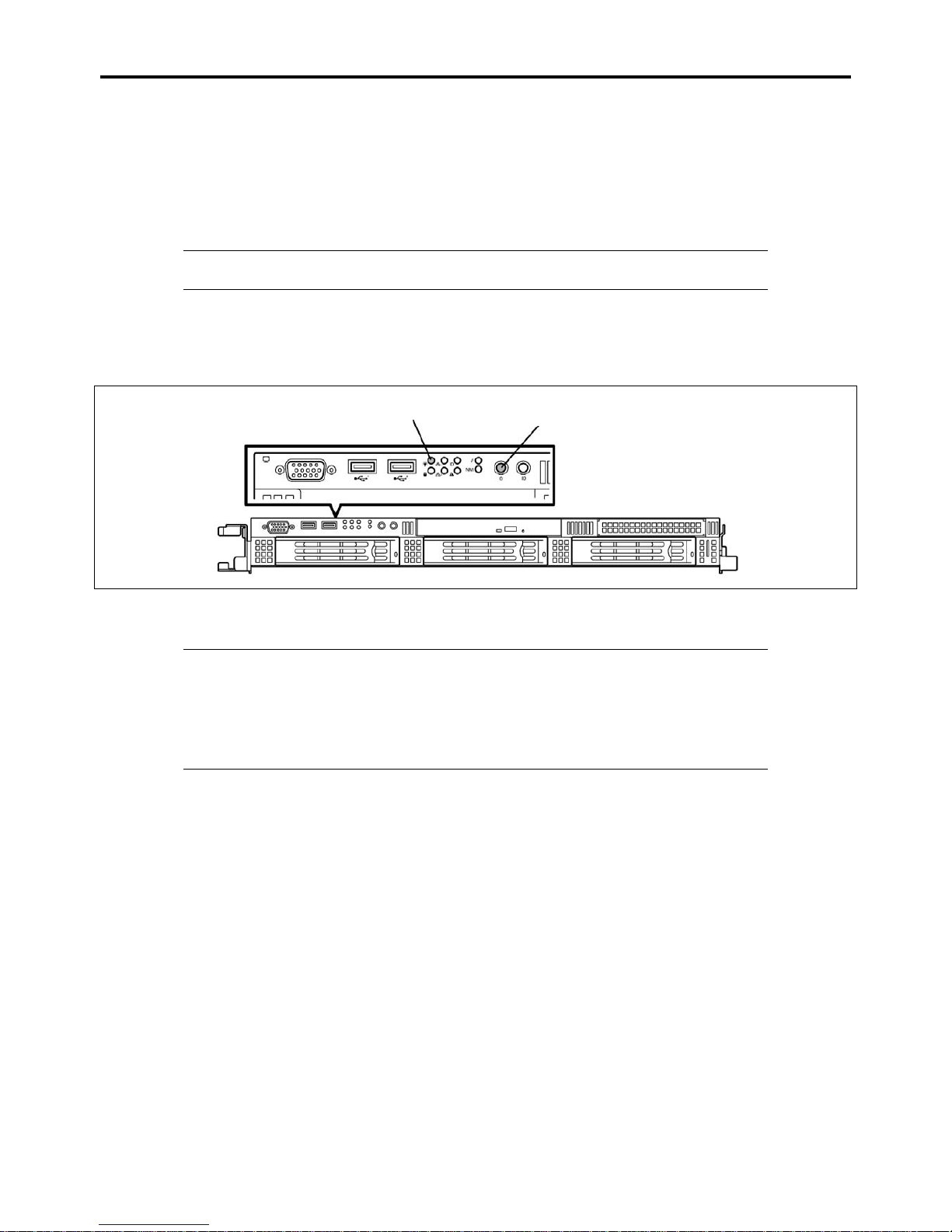
3-22 Setting Up Your Server
TURNING ON THE SERVER
Power on your system as follows.
1. Make sure all external devices, such as a video display, keyboard, and mouse (optional) have been connected, and the
power cords are connected.
2. Power on the video display and any other external devices.
NOTE: If the server power cord(s) is connected to a power control unit such as an UPS
(Uninterruptible Power Supply), make sure that the power control unit is powered on.
3. Open the front bezel.
4. Press the POWER switch.
The POWER LED on the front of the server comes on.
POWER switch
POWER LED
After a few seconds your system begins the internal Power-On Self Test (POST). POST automatically checks the
system board, CPU module, memory, keyboard, and most installed peripheral devices.
IMPORTANT:
Always allow POST to complete before powering down your system.
The server management logic on your system board monitors and logs system voltage changes.
When powering down your system you may experience a 30-second delay from the time you
press the push-button power on/off switch on the front panel and your system powering down.
This is normal system operation and is required by the server management logic.
If you have problems powering on your system, see Chapter 8.
After you have successfully powered on your system, insert the ExpressBuilder DVD into the optical disk drive, reboot the
system and follow the screen prompts to run ExpressBuilder.
Page 93

Setting Up Your Server 3-23
INSTALLING THE OPERATING SYSTEM
See Chapter 5 for installing the Microsoft Windows Server 2003 operating systems.
To install the other operating systems listed above, contact your service representative.
IMPORTANT: Before installing the operating system, adjust the system date and time by using
the BIOS setup utility "SETUP." See the next chapter for details.
INSTALLING UTILITIES
Install the utilities that come with the server. See Chapter 6 for details.
MAKING BACKUP COPIES OF SYSTEM INFORMATION
The system information includes the current BIOS settings and any specific information for the server.
Save the information after completing the system setup.
Without the backup data, you will not be able to recover the information.
You can save the information by the following process.
1. Insert the ExpressBuilder DVD into the optical disk drive and reboot the system.
2. Select [Tool menu (Normal mode)].
3. Select [English].
4. Select [Maintenance Utility].
5. Select [System Information Management].
6. Insert a floppy disk into the floppy disk drive.
7. Select [Save].
Page 94

3-24 Setting Up Your Server
(This page is intentionally left blank.)
Page 95

Chapter 4
Configuring Your Server
Configuration and setup utilities are used to change your system configuration. You can configure your system, as well as
option boards you may add to your system, using the BIOS SETUP Utility. Several unique system parameters are configured
using the BIOS SETUP, which is stored in the system FLASH memory.
The RAID configuration utility configures the RAID System and logical drives connected to the Onboard RAID Controller or
Internal RAID Controller.
If your system has been factory configured, the BIOS SETUP or RAID configuration utility do not need to be run unless you
want to change the password or security features, add certain types of option boards or devices, upgrade your system board, or
change the RAID configuration.
This chapter also provides information on several system configuration parameters that are set by jumpers on the system board.
However, these parameters do not usually require change.
SYSTEM BIOS (SETUP)
The SETUP utility is used to change system configuration parameters. This utility is pre-installed in the flash memory of the
server and ready to run.
The server is configured with the correct parameters using the SETUP utility and shipped in the best conditions. Thus, you
don't need to use the SETUP utility in most cases. However, you might wish to use the SETUP utility in the cases described
below.
IMPORTANT:
The SETUP utility is intended for system administrator use only.
The SETUP utility allows you to set a password. The server is provided with two levels of
password: Supervisor and User. With the Supervisor password, you can view and change all
system parameters of the SETUP utility. With the User password, system parameters available
for viewing and changing are limited.
Do not set any password before installing the OS.
The server contains the latest version of the SETUP utility. Dialog boxes appearing on your
SETUP utility, thus, may differ from descriptions in this manual. If you find anything unclear,
see the online help or ask your service representative.
Use the Exit menu when exiting the SETUP utility. Exiting the utility with the POWER switch
or reset operation causes the stored parameters to be lost.
Page 96
4-2 Configuring Your Server
Starting SETUP Utility
Powering on the server starts POST (Power On Self-Test) and displays its check results. If the Bull logo is displayed, press
Esc.
After a few seconds, the following message appears at bottom left on the screen.
Press <F2> to enter SETUP
Press F2 to start the SETUP utility and display its Main menu.
If you have previously set a password with the SETUP utility, the password entry screen appears. Enter the password.
Enter password:[ ]
Up to three password entries will be accepted. If you fail to enter the password correctly for three consecutive times, the server
halts. (You can no longer use it.) Power off the server.
NOTE: The server is provided with two levels of password: Supervisor and User. With the
Supervisor password, you can view and change all system parameters. With the User password,
system parameters available for viewing and changing are limited.
Page 97
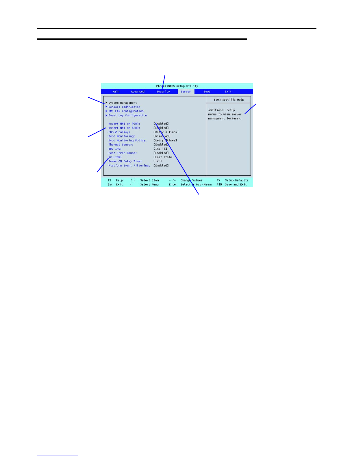
Configuring Your Server 4-3
Description on On-Screen Items and Key Usage
Use the following keyboard keys to work with the SETUP utility. (Key functions are also listed at the bottom of the screen.)
* The menus displayed in gray are for information only or are secured by BIOS password.
Cursor (↑, ↓):
Selects an item on the screen. The highlighted item is currently
selected.
Cursor (←, →):
Selects the Main, Advanced, Security, Server, Boot, or Exit menu.
– and +:
Changes the value (parameter) of the selected item. When a
submenu option (an option preceded by "
Æ") is selected, these
keys are disabled.
Enter Press Enter to select (determine) parameters.
Esc
Exit SETUP and return to the previous screen.
F9:
Sets the parameter of the currently displayed item back to the
factory set parameter.
F10:
Save and exit the SETUP utility.
Indicates there
are submenus.
Parameter (high-lights upon selection) menu
Indicates the current menu.
Setup item
menu
(s)
*
Online help
window
Explanation of key
functions menu
Page 98

4-4 Configuring Your Server
Menu and Parameter Descriptions
The SETUP utility has the following six major menus:
Main
Advanced
Security
Server
Boot
Exit
To set functions, select a submenu from the above menus. The following describes available functions and parameters, as well
as the factory-set, for each menu.
Page 99
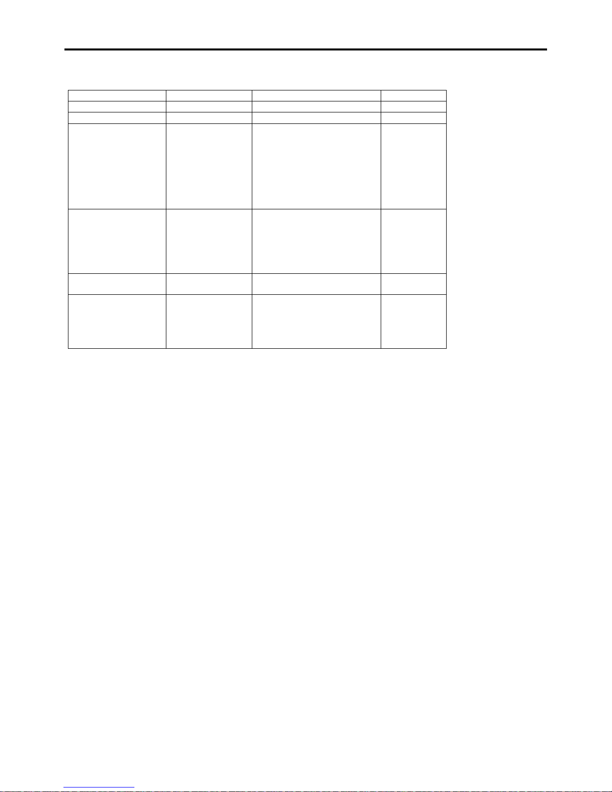
Configuring Your Server 4-5
Main
Option Parameter Description Your Setting
System Time HH:MM:SS Set the system time.
System Date MM/DD/YYYY Set the system date.
Hard Disk Pre-Delay [Disabled]
3 seconds
6 seconds
9 seconds
12 seconds
15 seconds
21 seconds
30 seconds
Allows to add a delay before the
first access of a hard disk drive
by the BIOS.
SATA Port 0
SATA Port 1
SATA Port 2
SATA Port 3
SATA Port 4
SATA Port 5
Select submenu
Set the information on the device
connected to each channel on
the submenu. The settings of
some items may be changed.
However, leave the items as
they are at the shipment.
Processor Settings Select submenu
Shows the processor settings
submenu.
Language [English]
Français
Deutsch
Español
Italiano
Select which language BIOS
displays.
[ ]: Factory-set
Page 100
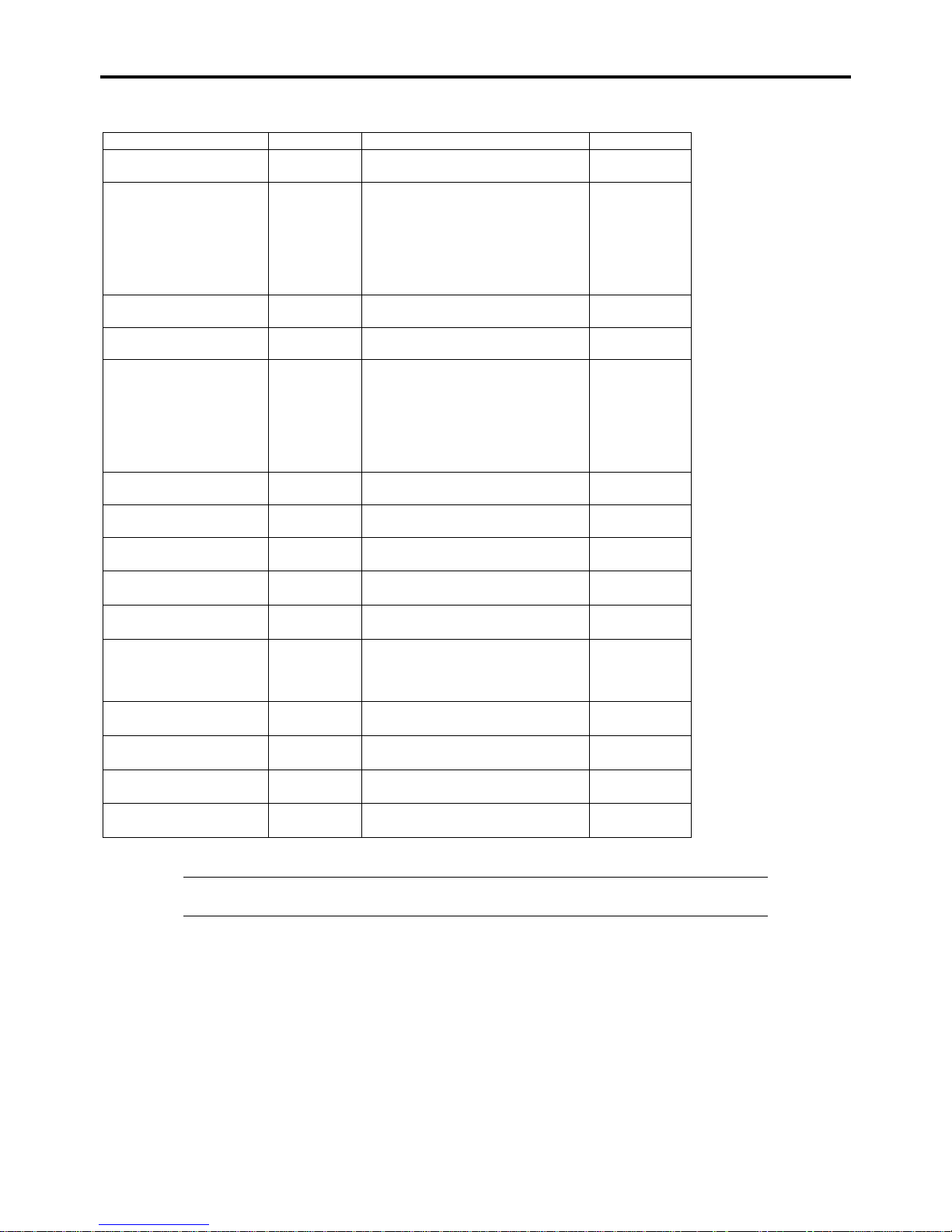
4-6 Configuring Your Server
Processor Settings
Option Parameter Description Your Setting
Processor Speed Setting nnn GHz
Displays clock speed for the
processor. (View only)
Processor 1 CPUID Numeral
Disabled
Not Installed
Displays CPU ID for processor 1, if
present.
"Disabled" indicates that the
processor is defected.
"Not Installed" indicates that no
processor is installed.
(View only)
Processor 1 L2 Cache nnn KB
Displays L2 cache size for
processor 1.
Processor 1 L3 Cache nnn KB
Displays L3 cache size for
processor 1.
Processor 2 CPUID Numeral
Disabled
Not Installed
Displays CPU ID for processor 2, if
present.
"Disabled" indicates that the
processor is defected.
"Not Installed" indicates that no
processor is installed.
(View only)
Processor 2 L2 Cache nnn KB
Displays L2 cache size for
processor 2.
Processor 2 L3 Cache nnn KB
Displays L3 cache size for
processor 2.
Active Processor Cores [ALL]
12
Specifies the number of valid cores
in the processor.
Hyper Threading
Technology
Disabled
[Enabled]
Displayed only when the CPU
supports this feature.
Execute Disable Bit [Enabled]
Disabled
Displayed only when the CPU
supports Execute Disable Bit.
Intel SpeedStep(R)
Technology
[Enabled]
Disabled
If set to "Enabled", Intel Turbo Boost
Technology is also enabled (only
when the CPU supports this
feature).
C1 Enhanced Mode [Enabled]
Disabled
Enables or disables the C1
Enhanced Mode.
Virtualization Technology [Enabled]
Disabled
Enables or disables the Intel(R)
virtualization technology.
Hardware Prefetcher [Enabled]
Disabled
Enables or disables the hardware
prefetcher.
Adjacent Cache Line
Prefetch
[Enabled]
Disabled
Enables or disables the optimization
of an access from memory to cache.
[ ]: Factory-set
NOTE: If the CPU that supports Intel(R) Turbo Boost Technology is installed, [Turbo Boost
Technology] is always set to [Enabled].
 Loading...