

Page 1

NovaScale T840 E2
User's Guide
NOVASCALE
REFERENCE
86 A1 43FB 01
Page 2

Page 3

NOVASCALE
NovaScale T840 E2
User's Guide
Hardware
May 2009
BULL CEDOC
357 AVENUE PATTON
B.P.20845
49008 ANGERS CEDEX 01
FRANCE
REFERENCE
86 A1 43FB 01
Page 4

Proprietary Notice and Liability Disclaimer
The information disclosed in this document, including all designs and related materials, is the valuable property of
NEC Computers and/or its licensors. NEC Computers and/or its licensors, as appropriate, reserve all patent,
copyright and other proprietary rights to this document, including all design, manufacturing, reproduction, use, and
sales rights thereto, except to the extent said rights are expressly granted to others.
To allow for design and specification improvements, the information in this document is subject to change at any
time, without notice. Reproduction of this document or portions thereof without prior written approval of NEC
Computers is prohibited.
The Bull product(s) discussed in this document are warranted in accordance with the terms of the Warranty Statement
accompanying each product. However, actual performance of each product is dependent upon factors such as
system configuration, customer data, and operator control. Since implementation by customers of each product may
vary, the suitability of specific product configurations and applications must be determined by the customer and is
not warranted by Bull.
Trademarks
NEC ESMPRO, NEC DianaScope, NEC MWA, and ExpressBuilder are trademarks or registered trademarks of NEC
Corporation.
NovaScale is a registered trademark of Bull SAS.
Adobe, and Adobe Acrobat are registered trademarks of Adobe Systems, Incorporated.
Microsoft, Microsoft Windows, Windows NT, Windows 95, Windows 98, Windows2000 and Windows Server
2003 are all registered trademarks of Microsoft Corporation.
MS-DOS is a registered trademark of Microsoft Corporation.
Intel and Xeon are registered trademarks of Intel Corporation.
All other product, brand, or trade names used in this publication are the trademarks or registered trademarks of their
respective trademark owners.
Copyright © NEC Computers SAS 2006
Suggestions and criticisms concerning the form, content, and presentation of this manual
are invited. A form is provided at the end of this manual for this purpose.
The information in this document is subject to change without notice. Bull will not be liable for errors contained
herein, or for incidental or consequential damages in connection with the use of this material.
Page 5

User Guide
5
www.bull.com
Text Conventions . . . . . . . . . . . . . . . . . . . . . . . . . . . . . . . . . . . . . . . . . . . . . . . . . . . . . . . . . . . . . 9
Safety Notices . . . . . . . . . . . . . . . . . . . . . . . . . . . . . . . . . . . . . . . . . . . . . . .10
Regulatory Information . . . . . . . . . . . . . . . . . . . . . . . . . . . . . . . . . . . . . . . . . . . . . . . . . . . . . . . 10
European Notice ............................................................................................................ 10
USA and Canada Notice ................................................................................................ 10
Modifications to the Product .......................................................................................... 11
Connections and Remote Earths .................................................................................... 11
Power Supply and Cables .............................................................................................. 11
Batteries .........................................................................................................................12
Chassis Cover Removal and Replacement .................................................................... 12
Laser Compliance Statement ......................................................................................... 12
Warning - Hazardous Voltage! ...................................................................................... 13
Warning -Avoid Electrostatic Discharge! ...................................................................... 13
Product Disposal ............................................................................................................ 13
T840 E2 System Features . . . . . . . . . . . . . . . . . . . . . . . . . . . . . . . . . . . . . .14
Related Documents . . . . . . . . . . . . . . . . . . . . . . . . . . . . . . . . . . . . . . . . . . . . . . . . . . . . . . . . . . 15
T840 E2 System Chassis Features . . . . . . . . . . . . . . . . . . . . . . . . . . . . . . . . . . . . . . . . . . . . . . 16
Front View .....................................................................................................................16
Front Bezel Lock ........................................................................................................... 16
Front view details ........................................................................................................... 17
Front Lamps Indication .................................................................................................. 18
T840 E2 Rear View ....................................................................................................... 21
Rear Lamps Indication ................................................................................................... 22
T840 E2 Internal View .................................................................................................. 24
Motherboard . . . . . . . . . . . . . . . . . . . . . . . . . . . . . . . . . . . . . . . . . . . . . . . . . . . . . . . . . . . . . . . . 25
Motherboard Layout .....................................................................................................25
Motherboard Jumpers ....................................................................................................26
Rear Panel Connectors ................................................................................................... 28
Processor ........................................................................................................................ 28
RAID Support ................................................................................................................ 28
Memory Configuration .................................................................................................. 29
Memory Sparing and Mirroring ..................................................................................... 30
BMC Controller ............................................................................................................. 30
Video .............................................................................................................................. 32
Network Controller ........................................................................................................ 32
ACPI .............................................................................................................................. 33
Keyboard and Mouse ..................................................................................................... 33
Optional Features . . . . . . . . . . . . . . . . . . . . . . . . . . . . . . . . . . . . . . . . . . . . . . . . . . . . . . . . . . . . 35
DVD Writer Combination Drive ................................................................................... 36
DAT72 Tape Backup Unit (USB) ................................................................................. 37
DAT160 Tape Backup Unit (USB) ............................................................................... 38
LTO-3 HH Tape Drive (SCSI) ...................................................................................... 39
LTO-4 HH Tape Drive (SAS) ....................................................................................... 40
Intel Pro/1000 PT Single Port LAN Board .................................................................... 41
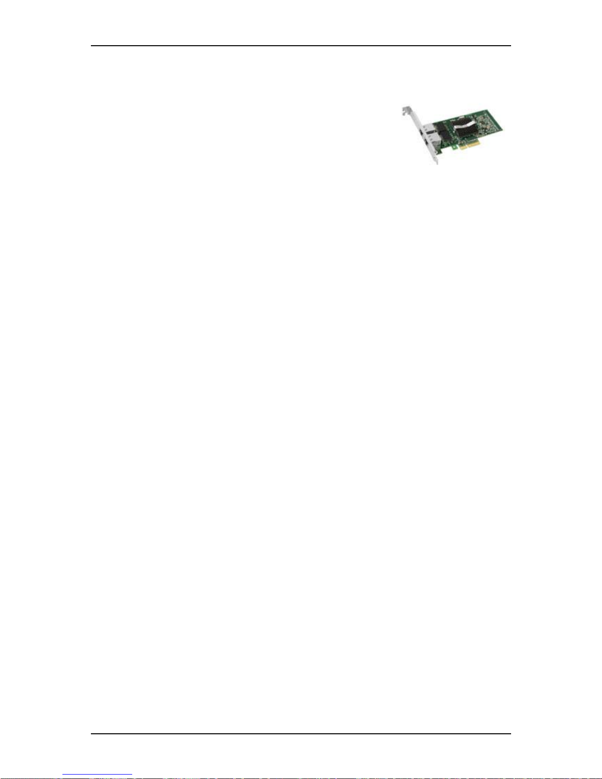
Intel Pro/1000 PT Dual Port LAN Board ...................................................................... 42
S-ATA Hard Disk Drive ................................................................................................ 44
SAS Hard Disk Drive .................................................................................................... 45
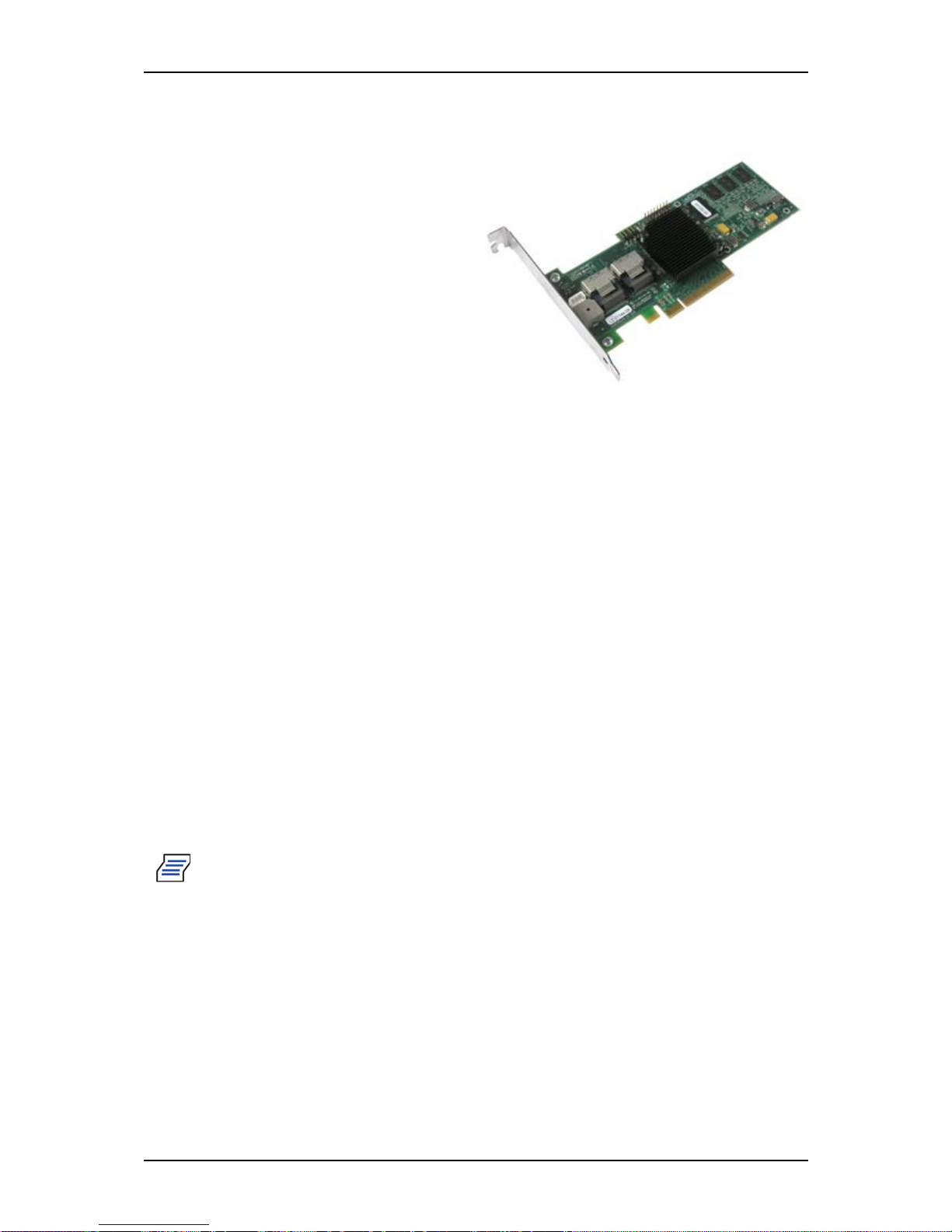
LSI 8708EM2 SAS/SATA RAID Controller ................................................................ 46
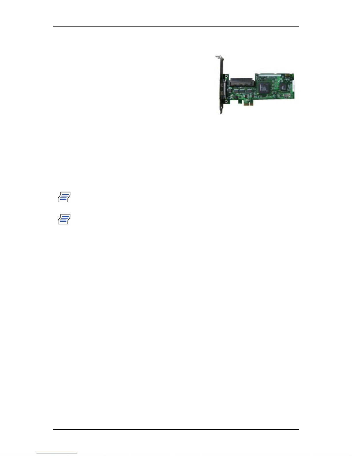
Adaptec SCSI Card 29320LPE ...................................................................................... 47
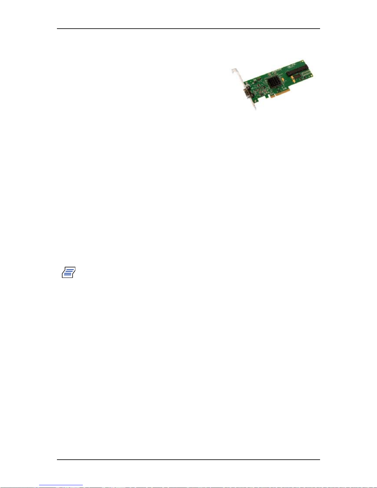
LSI SAS 3442E-R .......................................................................................................... 48
Page 6

User Guide
6
www.bull.com
Setting Up Your System . . . . . . . . . . . . . . . . . . . . . . . . . . . . . . . . . . . . . . .49
Unpacking the System . . . . . . . . . . . . . . . . . . . . . . . . . . . . . . . . . . . . . . . . . . . . . . . . . . . . . . . . 50
T840 E2 Rack Conversion Kit Assembly . . . . . . . . . . . . . . . . . . . . . . . . . . . . . . . . . . . . . . . . . 51
Unpacking the Rack Conversion Kit ............................................................................. 51
Before You Begin .......................................................................................................... 55
Static Precautions ........................................................................................................... 55
Assembly .......................................................................................................................55
Modifying the server from tower to rack-mount type ................................................... 57
Assembling the Front and Rear Parts of Support Rails ................................................. 60
Installing the server in the rack ...................................................................................... 61
Making Connections . . . . . . . . . . . . . . . . . . . . . . . . . . . . . . . . . . . . . . . . . . . . . . . . . . . . . . . . . . 63
T840 E2 Power Supply . . . . . . . . . . . . . . . . . . . . . . . . . . . . . . . . . . . . . . . . . . . . . . . . . . . . . . . . 64
Connecting the Power Cord(s) ....................................................................................... 64
Hot-Swappable Power Supply Features ........................................................................ 65
Using the System . . . . . . . . . . . . . . . . . . . . . . . . . . . . . . . . . . . . . . . . . . . . .67
Powering On your System . . . . . . . . . . . . . . . . . . . . . . . . . . . . . . . . . . . . . . . . . . . . . . . . . . . . . 68
Powering Off your System . . . . . . . . . . . . . . . . . . . . . . . . . . . . . . . . . . . . . . . . . . . . . . . . . . . . . 69
Forcing a Power Shutdown . . . . . . . . . . . . . . . . . . . . . . . . . . . . . . . . . . . . . . . . . . . . . . . . . . . . 70
Resetting the System . . . . . . . . . . . . . . . . . . . . . . . . . . . . . . . . . . . . . . . . . . . . . . . . . . . . . . . . . 71
Configuring Your System . . . . . . . . . . . . . . . . . . . . . . . . . . . . . . . . . . . . . .72
Configuring RAID . . . . . . . . . . . . . . . . . . . . . . . . . . . . . . . . . . . . . . . . . . . . . . . . . . . . . . . . . . . . 73
RAID Configuration Utility ........................................................................................... 73
RAID Levels .................................................................................................................. 74
RAID Configuration using the Intel® Embedded Server RAID BIOS Configuration Utility . 76
Description ..................................................................................................................... 76
Enabling RAID in the BIOS .......................................................................................... 76
Entering the Intel Embedded Server RAID BIOS Configuration Utility ...................... 76
Setting Up the RAID Feature ......................................................................................... 76
RAID Configuration using the LSI Logic Software RAID Configuration Utility . . . . . . . . . . . 77
Running the Setup Utility .............................................................................................. 77
Operating Procedures for the Setup Utility .................................................................... 79
Manual Rebuild ............................................................................................................. 84
Setting a Hot Spare ........................................................................................................ 86
Check Consistency ........................................................................................................ 87
Others Operations .......................................................................................................... 88
RAID Configuration using the Universal RAID Utility . . . . . . . . . . . . . . . . . . . . . . . . . . . . . . . 89
Configuring the BMC . . . . . . . . . . . . . . . . . . . . . . . . . . . . . . . . . . . . . . . . . . . . . . . . . . . . . . . . . 90
Overview ........................................................................................................................ 90
Installation ..................................................................................................................... 90
SELVIEW ...................................................................................................................... 90
SYSCFG ........................................................................................................................ 91
Upgrading Your System . . . . . . . . . . . . . . . . . . . . . . . . . . . . . . . . . . . . . . .96
General Safety Information . . . . . . . . . . . . . . . . . . . . . . . . . . . . . . . . . . . . . . . . . . . . . . . . . . . . 96
Static Precautions . . . . . . . . . . . . . . . . . . . . . . . . . . . . . . . . . . . . . . . . . . . . . . . . . . . . . . . . . . . . 96
Equipment Log . . . . . . . . . . . . . . . . . . . . . . . . . . . . . . . . . . . . . . . . . . . . . . . . . . . . . . . . . . . . . . 96
Tools Recommended for Upgrading Your System . . . . . . . . . . . . . . . . . . . . . . . . . . . . . . . . . 97
Preparing Your System for Upgrade . . . . . . . . . . . . . . . . . . . . . . . . . . . . . . . . . . . . . . . . . . . . . 97
Removing the Left Side Door . . . . . . . . . . . . . . . . . . . . . . . . . . . . . . . . . . . . . . . . . . . . . . . . . . . 98
Removing the Front Panel . . . . . . . . . . . . . . . . . . . . . . . . . . . . . . . . . . . . . . . . . . . . . . . . . . . . 100
Installing or Removing a 5.25-inch Device . . . . . . . . . . . . . . . . . . . . . . . . . . . . . . . . . . . . . . . 101
Adding a 5.25-inch Device .......................................................................................... 101
Removing a 5.25-inch device ...................................................................................... 101
Page 7

User Guide
7
www.bull.com
Installing or Removing Hard Disk Drives . . . . . . . . . . . . . . . . . . . . . . . . . . . . . . . . . . . . . . . . 103
3.5-inch Hard Disk Drive (3.5-inch Disk Model) ........................................................ 103
2.5-inch Hard Disk Drive (2.5-inch Disk Model) ........................................................ 106
Upgrading Microprocessor . . . . . . . . . . . . . . . . . . . . . . . . . . . . . . . . . . . . . . . . . . . . . . . . . . . 108
Installing a CPU ........................................................................................................... 108
Removing a Processor ................................................................................................. 111
Upgrading Random Access Memory (RAM) . . . . . . . . . . . . . . . . . . . . . . . . . . . . . . . . . . . . . . 113
Recommended Memory Configuration ....................................................................... 113
Removing and Replacing a DDR3 module .................................................................. 113
Replacing the Battery . . . . . . . . . . . . . . . . . . . . . . . . . . . . . . . . . . . . . . . . . . . . . . . . . . . . . . . . 115
Installing and Removing an Expansion Card . . . . . . . . . . . . . . . . . . . . . . . . . . . . . . . . . . . . . 116
Specific Recommendations .......................................................................................... 116
Installing an Expansion Card ....................................................................................... 117
Removing an Expansion Card ..................................................................................... 118
Cabling SATA Devices . . . . . . . . . . . . . . . . . . . . . . . . . . . . . . . . . . . . . . . . . . . . . . . . . . . . . . . 119
The S-ATA Cable ........................................................................................................ 119
System Power Cables ................................................................................................... 119
Cabling a S-ATA Drive ............................................................................................... 120
Cabling SAS Devices . . . . . . . . . . . . . . . . . . . . . . . . . . . . . . . . . . . . . . . . . . . . . . . . . . . . . . . . 121
The SAS Cable ............................................................................................................. 121
Interrupt Requests . . . . . . . . . . . . . . . . . . . . . . . . . . . . . . . . . . . . . . . . . . . . . . . . . . . . . . . . . . 122
Software . . . . . . . . . . . . . . . . . . . . . . . . . . . . . . . . . . . . . . . . . . . . . . . . . . .123
Installing and Using Utilities . . . . . . . . . . . . . . . . . . . . . . . . . . . . . . . . . . . . . . . . . . . . . . . . . . 123
With the ExpressBuilder DVD you can: ...................................................................... 123
Software End-User License Agreement ...................................................................... 123
Utilities ......................................................................................................................... 123
ExpressBuilder . . . . . . . . . . . . . . . . . . . . . . . . . . . . . . . . . . . . . . . . . . . . . . . . . . . . . . . . . . . . . 124
ExpressBuilder (Windows-Based) ............................................................................... 124
Bull System Client
and Bull System Area Manager . . . . . . . . . . . . . . . . . . . . . . . . . . . . . . . . . . . . . . . . . . . . . . . . 125
Bull System Client ....................................................................................................... 125
Bull System Area Manager .......................................................................................... 125
Bull System Client and Bull System Area Manager Scopes ....................................... 126
Installing the Operating System with Express Setup . . . . . . . . . . . . . . . . . . . . . . . . . . . . . . 127
Microsoft Windows Server 2003 . . . . . . . . . . . . . . . . . . . . . . . . . . . . . . . . . . . . . . . . . . . . . . . 128
Installation Notice ........................................................................................................ 128
Installing Windows Server 2003 .................................................................................. 129
Updating the System . . . . . . . . . . . . . . . . . . . . . . . . . . . . . . . . . . . . . . . . . . . . . . . . . . . . . . . . 131
Installing Drivers or Software . . . . . . . . . . . . . . . . . . . . . . . . . . . . . . . . . . . . . . . . . . . . . . . . . 132
Installing Microsoft Windows Server 2008 . . . . . . . . . . . . . . . . . . . . . . . . . . . . . . . . . . . . . . 133
Installing the Operating System without Express Setup . . . . . . . . . . . . . . . . . . . . . . . . . . . 134
Microsoft Windows Server 2003 . . . . . . . . . . . . . . . . . . . . . . . . . . . . . . . . . . . . . . . . . . . . . . . 135
Installing Microsoft Windows Server 2003 ................................................................. 136
Creating the Windows 2003 OEM-DISK from the ExpressBuilder ............................ 136
Reinstallation to Multiple Logical drives .................................................................... 138
Updating the System .................................................................................................... 139
Installing Drivers or Software ...................................................................................... 139
Available Switch Options for Windows Server 2003 Boot.ini File ............................ 140
Collecting the Memory Dump ..................................................................................... 140
Installing Microsoft Windows Server 2008 . . . . . . . . . . . . . . . . . . . . . . . . . . . . . . . . . . . . . . . 141
Maintenance . . . . . . . . . . . . . . . . . . . . . . . . . . . . . . . . . . . . . . . . . . . . . . . .142
Making Backup Copies . . . . . . . . . . . . . . . . . . . . . . . . . . . . . . . . . . . . . . . . . . . . . . . . . . . . . . . 142
Cleaning . . . . . . . . . . . . . . . . . . . . . . . . . . . . . . . . . . . . . . . . . . . . . . . . . . . . . . . . . . . . . . . . . . . 143
Page 8

User Guide
8
www.bull.com
Cleaning the External Surfaces of the system ............................................................ 143
Cleaning the Interior of the system .............................................................................. 143
Cleaning the Keyboard ................................................................................................ 144
Cleaning the Mouse ..................................................................................................... 144
Cleaning an Optical Disc Drive ................................................................................... 146
Care and Handling . . . . . . . . . . . . . . . . . . . . . . . . . . . . . . . . . . . . . . . . . . . . . . . . . . . . . . . . . . 147
Solving Problems . . . . . . . . . . . . . . . . . . . . . . . . . . . . . . . . . . . . . . . . . . .148
Static Precautions . . . . . . . . . . . . . . . . . . . . . . . . . . . . . . . . . . . . . . . . . . . . . . . . . . . . . . . . . . . 148
Troubleshooting Guide . . . . . . . . . . . . . . . . . . . . . . . . . . . . . . . . . . . . . . . . . . . . . . . . . . . . . . 149
System Viewers ........................................................................................................... 149
Problems at initial System Start-up . . . . . . . . . . . . . . . . . . . . . . . . . . . . . . . . . . . . . . . . . . . . 150
Problems After the System Has Been Running Correctly . . . . . . . . . . . . . . . . . . . . . . . . . . 151
Problems Running New Application Software . . . . . . . . . . . . . . . . . . . . . . . . . . . . . . . . . . . . 152
Problems and Suggestions . . . . . . . . . . . . . . . . . . . . . . . . . . . . . . . . . . . . . . . . . . . . . . . . . . . 153
Problems with the System ............................................................................................ 154
Problems with Windows Server 2003 ......................................................................... 157
Problems with ExpressBuilder ..................................................................................... 159
Problems with Express Setup ...................................................................................... 160
Problems with Disk Array Configuration ................................................................... 161
Collecting Event Log . . . . . . . . . . . . . . . . . . . . . . . . . . . . . . . . . . . . . . . . . . . . . . . . . . . . . . . . 161
Collecting Configuration Information . . . . . . . . . . . . . . . . . . . . . . . . . . . . . . . . . . . . . . . . . . 161
Collecting Dr. Watson Diagnostic Information . . . . . . . . . . . . . . . . . . . . . . . . . . . . . . . . . . . 162
Memory Dump (depending on your configuration) . . . . . . . . . . . . . . . . . . . . . . . . . . . . . . . . 162
If You Need Assistance . . . . . . . . . . . . . . . . . . . . . . . . . . . . . . . . . . . . . . . . . . . . . . . . . . . . . . 162
Error Messages . . . . . . . . . . . . . . . . . . . . . . . . . . . . . . . . . . . . . . . . . . . . . . . . . . . . . . . . . . . . . 163
POST Error Messages .................................................................................................. 163
POST Error Beep Codes .............................................................................................. 163
POST Error Pause Option ............................................................................................ 164
Diagnostic LEDs .......................................................................................................... 164
Diagnostic LEDs . . . . . . . . . . . . . . . . . . . . . . . . . . . . . . . . . . . . . . . . . . . . . . . . . . . . . . . . . . . . 170
BIOS Setup Utility . . . . . . . . . . . . . . . . . . . . . . . . . . . . . . . . . . . . . . . . . . .171
Using the BIOS Setup Utility . . . . . . . . . . . . . . . . . . . . . . . . . . . . . . . . . . . . . . . . . . . . . . . . . . 171
BIOS Setup Configuration Settings . . . . . . . . . . . . . . . . . . . . . . . . . . . . . . . . . . . . . . . . . . . . 172
Main Menu .................................................................................................................. 173
Advanced Menu .......................................................................................................... 174
Security Menu ............................................................................................................. 185
Server Management Menu .......................................................................................... 187
Boot Options Menu ..................................................................................................... 190
Boot Manager Menu .................................................................................................... 194
Error Manager Menu ................................................................................................... 195
EXit Menu .................................................................................................................... 196
Updating the BIOS . . . . . . . . . . . . . . . . . . . . . . . . . . . . . . . . . . . . . . . . . . . . . . . . . . . . . . . . . . 197
Recording the Current BIOS Settings .......................................................................... 197
Performing the BIOS Update ....................................................................................... 197
How to Identify BIOS Revision Level . . . . . . . . . . . . . . . . . . . . . . . . . . . . . . . . . . . . . . . . . . . 198
Recovering BIOS . . . . . . . . . . . . . . . . . . . . . . . . . . . . . . . . . . . . . . . . . . . . . . . . . . . . . . . . . . . . 199
T840 E2 Specifications . . . . . . . . . . . . . . . . . . . . . . . . . . . . . . . . . . . . . . .200
T840 E2 Equipment Log . . . . . . . . . . . . . . . . . . . . . . . . . . . . . . . . . . . . . . . . . . . . . . . . . . . . . . 202
Hardware ...................................................................................................................... 203
Software ....................................................................................................................... 206
Page 9
User Guide
9
www.bull.com
T ext Conventions
This guide uses the following text conventions.
Warnings, cautions, and notes have the following meanings:
Warning: Warnings alert you to situations that could result in serious
personal injury or loss of life.
Caution: Cautions indicate situations that can damage the system hardware
or software.
Note: Notes give important information about the material being described.
■ Names of keyboard keys are printed as they appear on the keyboard. For example,
Ctrl, Alt, or Enter.
■ Text or keystrokes that you enter appear as boldface type. For example, type
abc123 and press ENTER.
■ File names are printed in upper case letters. For example, AUTOEXEC.BAT.
Page 10

User Guide
10
www.bull.com
Safety Notices
Caution: To reduce the risk of electric shock which could cause personal
injury, follow all the safety notices.
Symbols are shown in your documentation and on your equipment to indicate
safety hazards.
Regulatory Information
European Notice
Products with the CE marking comply with both the Electromagnetic Compatibility
Directive (2004/108/EEC) and the Low Voltage Directive (2006/95/EEC) - modified
by the Directive 93/68/EEC - issued by the Commission of the European Economic
Community.
Compliance with these directives implies conformity to the following European
Standards:
■ EN55022: Radio disturbance characteristics
■ EN55024 : Immunity characteristics
■ EN6100-3-2: Limitation of harmonic current emissions
■ EN6100-3-3: Limitation of voltage fluctuation and flicker in low-voltage supply
system
■ EN60950-1: Product Safety. If your system includes a telecommunication network
board, the input/output socket is classified as Telecommunication Network Voltage
(TNV-3).
Warning: This is a Class A product. In domestic environment this product
may cause radio interference in which case the user may be required to
take adequate measures (EN55022).
USA and Canada Notice
Products with UL marking comply with the following UL standards:
■ UL 1950 (3rd edition 1998)
Products with FCC marking comply with the following FCC standards
■ FCC part 15
The model type/ref. used for UL and FCC certification can be found on the regulatory
labels stuck on your system.
Page 11

User Guide
11
www.bull.com
The equipment has been tested and found to comply with the limits for a Class A or B
digital device, pursuant to part 15 of the FCC rules. These limits are designed to
provide reasonable protection against harmful interference when the equipment is
operated in a commercial environment. This equipment generates, uses, and can radiate
radio frequency energy, and if not installed and used in accordance with the instruction
manual, may cause harmful interference to radio communications. Operation of this
equipment in a residential area is likely to cause harmful interference, in which case the
user will be required to correct the interference at his own expense.
Modifications to the Product
CE and FCC Marking
We cannot be held responsible for modifications made by the User and the
consequences thereof, which may alter the conformity of the product with the CE or
FCC Marking.
Connections and Remote Earths
PELV (Protected Extra Low Voltage)
To ensure the extra-low voltage integrity of the equipment, only connect equipment
with mains-protected electrically-compatible circuits to the external ports.
SELV (Safety Extra Low Voltage)
Every input and output of this product is classified as Safety Extra Low Voltage.
Remote Earths
To prevent electrical shock, connect all local (individual office) systems and system
support equipment to the same electrical circuit of the building wiring. If you are
unsure, check the building wiring to avoid remote earth conditions.
Building Supply
Only connect the equipment to a building supply that is in accordance with current
wiring regulations in your country. In the U.K., those are the IEE regulations.
Power Supply and Cables
Power Supply
■ The DC push-button on/off switch on the front panel does not turn off the system
AC power. +5vdc is present on the system board whenever the AC power cords are
connected between the system and an AC outlet. Before doing the procedures in
Page 12

User Guide
12
www.bull.com
this manual, make sure that your system is powered off and unplug the AC power
cords from the back of the chassis. Failure to disconnect power before opening
your system can result in personal injury and equipment damage.
■ Under no circumstances should the user attempt to disassemble the power supply.
The power supply has no user-replaceable parts. Inside the power supply are hazardous voltages that can cause serious personal injury. A defective power supply
must be returned to your dealer.
Cables
■ In the U.S.A. and Canada, the power cord must be a UL-listed detachable power
cord (in Canada, CSA-certified), type ST or SJT, 16 AWG, 3-conductor, provided
with a moulded-on NEMA type 5-15 P plug cap at one end and a moulded-on cord
connector body at the other end. The cord length must not exceed 9 feet (2.7
meters).
■ Outside the U.S.A. and Canada, the plug must be rated for 250 VAC, 10 amp
minimum, and must display an international agency approval marking. The cord
must be suitable for use in the end-user country. Consult your de aler or the local
electrical authorities if you are unsure of the type of power cord to use in your
country. The voltage change occurs via a switch in the power supply.
■ The detachable power supply cords are intended to serve as the disconnect devices.
■ For PLUGGABLE EQUIPMENT, the socket-outlet shall be installed near the
equipment and shall be easily accessible.
■ This equipment has a 3-wire, grounded power cords. To prevent electrical hazards,
do not remove or defeat the ground prong on the power cords. Replace a power
cord if it gets damaged. Contact your dealer for an exact replacement.
Batteries
Lithium batteries can be dangerous. Improper handling of lithium batteries may result
in an explosion. Dispose of lithium batteries as required by local ordinance. Also refer
to “Product Disposal” on page 13.
Chassis Cover Removal and Replacement
When servicing your system, make sure to replace the chassis cover and secure it with
the screws before plugging in the power cable and turning it on. The chassis cover
ensures proper airflow and cooling.
Laser Compliance Statement
The optical devices are tested and certified to be compliant with International Electrotechnical Commission IEC60825-1 and European EN60825-1 standards for Class 1
laser products.
Class 1 laser products are not considered hazardous. The optical devices are designed
such that there is never human access to laser radiation above a Class 1 level during
normal operation or prescribed maintenance conditions.
Page 13
User Guide
13
www.bull.com
The optical devices installed in your system are designed for use solely as a component
of such electronic product and therefore do not comply with the appropriate
requirements of Code of Federal Regulation Sec. 1040.10 and Sec. 1040.11 for
COMPLETE laser products
Warning - Hazardous Voltage!
Hazardous voltage is present inside your system when it is connected to an AC supply
even when the system’s power switch is off. Exposure to Hazardous Voltage could
cause personal injury. To reduce the risk of electric shock which could cause personal
injury, follow all safety notices. The symbols shown are used in your documentation
and on your equipment to indicate safety hazards.
Warning -Avoid Electrostatic Discharge!
Circuit cards and integrated circuits can be easily damaged by static electricity. To
reduce risk of damage, store them in protective packaging whenever they are not
installed in your system.
Before you install or remove memory modules, video memory, disk drives, circuit
cards or other devices, protect them from static electricity. To do so, make sure your
system’s power switch is OFF. Then, unplug the system’s AC power cord(s). Wear an
anti-static wrist strap (available at electronic supplies stores) to handle the device you
want to install. Be sure to connect the wrist strap to an unpainted metal portion of the
system chassis.
As an alternative, you can dissipate electrostatic buildup by touching an unpainted
metal portion of the system chassis with one hand. Handle the device you are installing
with the other hand, and maintain continuous contact with the unpainted portion of the
chassis until it is installed in the system.
Product Disposal
The Waste Electrical and Electronic Equipment (WEEE) Directive
requires that used electrical and electronic products must be disposed of
separately from normal household waste in order to promote reuse,
recycling and other forms of recovery and to reduce the quantity of
waste to be eliminated with a view to reducing landfill. WEEE includes
accessories such as keyboard, mouse, remote control, speakers, etc.
When you dispose of such products, please follow the agreement made
between you and us and/or your distributor.
Page 14

User Guide
14
www.bull.com
T840 E2 System Features
This system is a highly flexible and reliable server designed to offer the highest levels
of performance for the price range.
Its main features are:
■ The Intel® Tylersburg chipset.
■ The Intel® Xeon® Nehalem-EP and Westmere-DP processors.
■ The RAID technology, offering support for various RAID levels on Microsoft®
Windows® and Linux operating systems.
■ The tower chassis can easily be installed into a standard EIA 19-inch rack cabinet.
To get comfortable with your computer, we recommend you read this user guide. Keep
it in a safe place for future reference.
Page 15

User Guide
15
www.bull.com
Related Documents
On the ExpressBuilder disc in which you found this User’s Guide, you can also find
several other documents relevant to your system, options and accessories.
Some printed documents may also have been shipped with your system.
We recommend you read these additional documents as it becomes necessary when
setting up, using or upgrading your system.
Page 16
User Guide
16
www.bull.com
T840 E2 System Chassis Features
Front View
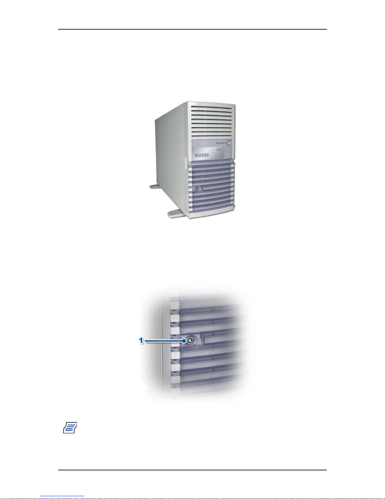
The following figure shows the location of the front system features.
Figure 1: Front View (with Front Bezel)
Front Bezel Lock
Lock the front bezel to prevent unauthorized access to the inside of the chassis.
Figure 2: Front Door Lock (A)
Note: the keys can be found behind the front bezel.
Page 17
User Guide
17
www.bull.com
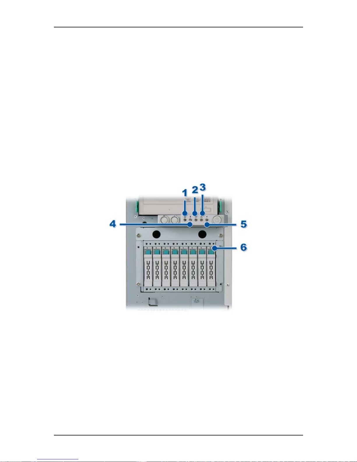
Front view details
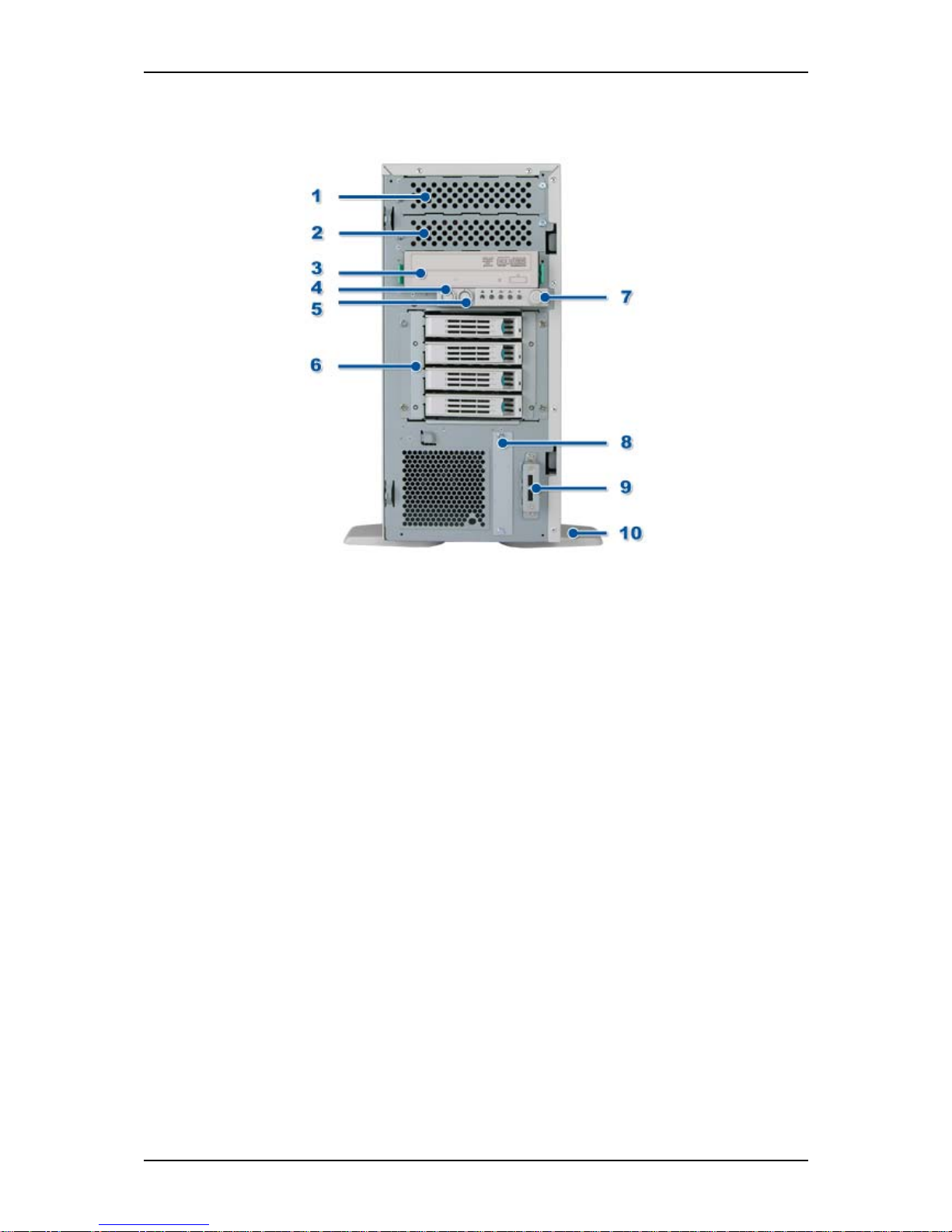
Figure 3: Front View (without Front Bezel)
1. 5.25-inch device bay.
A backup file device of 5.25-inch width such as DAT drive or MO drive may
be installed in the 5.25-inch device bay.
2. 5.25-inch device bay.
Refer to (1)
3. Optical disk drive.
The optical disk drive reads or writes data from/onto the inserted CD-ROM or
DVD-ROM.
The drive is equipped with the following:
■ Open/Close button to eject the tray
■ Access lamp that indicates the disk access status (lights while being
accessed)
■ Emergency hole to forcibly eject the tray
4. DUMP switch
5. RESET switch
6. Hard disk drive bay.
The bay can contain hard disk drives.
7. POWER/SLEEP switch.
The POWER/SLEEP switch is used to turn the power of the server ON/OFF. If
you press this switch once, the power is turned on with the lamp going on
green. If you press the switch again, the power is turned off.
Page 18
User Guide
18
www.bull.com
Some operating systems may provide the function of switching to a power
saving (sleep) mode. If you press the POWER/SLEEP switch once after the
setting, the system enters the power saving mode. If you press the switch again,
the system returns to the normal state.
8. 3.5-inch floppy disk drive bay.
Not used.
9. USB connectors.
The USB connectors allow the server to connect with USB 2.0 devices.
10. Stabilizers.
Use the stabilizers to prevent the server from falling down. Close the stabilizers
when laying the server down.
Front Lamps Indication
This section explains the indication and meanings of the system lamps located on the
front panel of your system.
Figure 4: Front panel lamps
1. STATUS lamp
Lights green: the server is operating normally.
blinks amber: the server is in abnormal state.
Off: the server is in abnormal state.
Refer to “Diagnostic LEDs” on page 170 to check the meaning and the
procedure for the STATUS lamp indication.
2. LAN access lamp (2)
Lights green: data is being transmitted or received.
3. LAN access lamp (1)
Lights green: data is being transmitted or received.
Page 19
User Guide
19
www.bull.com
4. DISK ACCESS lamp
Lights green: the hard disk drives is being accessed.
5. POWER/SLEEP lamp
Lights green: the server is powered.
Off: the server is off-powered.
If the OS supports a power-saving mode, the green lamp flashes while the
server is in this power-saving mode. Pressing the POWER switch places the
server back in the normal mode.
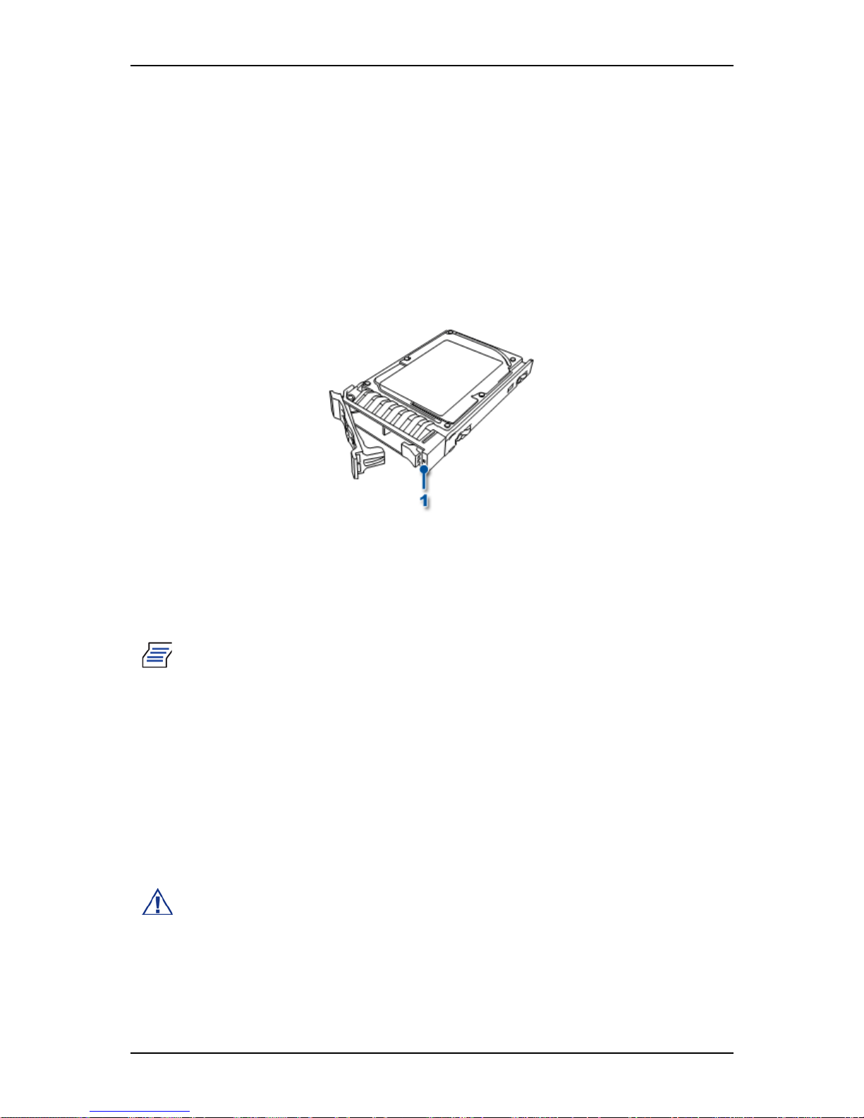
6. DISK lamps
Each hard disk drive has a DISK lamp on its front panel. (1) in below figure
Figure 5: Disk lamp
Lights green: power is supplied to the hard disk drive.
Blinks green: the hard disk drive is being accessed.
Lights amber: the hard disk drive is defective in the RAID System
configuration.
Note: While hard disk drives are in a RAID System configuration (RAID1/
RAID5, RAID6, RAID10, or RAID50), a single failed hard disk drive does
not affect the operation of the server.
However, we recommend you replace the failed hard disk drive and autorebuild (reconfigure) the hard disk drives as soon as possible. (You can hotswap such a failed hard disk drive.)
Blinks amber: during the data rebuild operation; when the defective hard disk
drive is replaced with a new one in the RAID System configuration.
Blinks green/amber: the hard disk drive is being rebuilt (this status is not a
failure).
Off: when the rebuild is terminated normally. The LED goes on amber if the
rebuild fails.
Caution: To abort a rebuild, power off the server. In such a case, restart the
server, hot-swap the failed hard disk drive, and restart rebuilding. Observe
the following notes to use the auto-rebuild feature.
• Do not power off the server. If the server is powered off before
rebuilding hard disk drives, the auto-rebuild feature will not start.
Page 20

User Guide
20
www.bull.com
• Wait at least 90 seconds between the removal of a failed hard disk drive
and the installation of a new hard disk drive.
• Do not replace another hard disk drive while a rebuilding is already in
progress.
Page 21
User Guide
21
www.bull.com
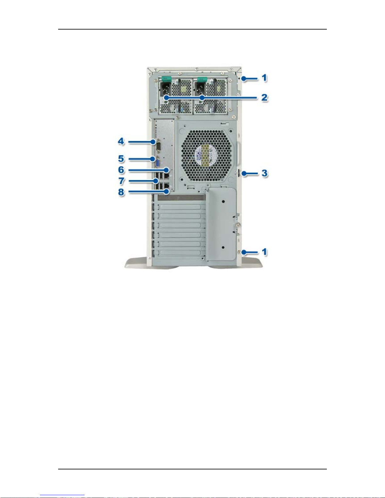
T840 E2 Rear View
Figure 6: Rear View
1. Fixing screws.
Secures the left side cover.
2. AC inlet.
The AC inlet is connected with the power cord.
3. Cover lock plate.
Installing a theft prevention device protects the internal components of the
server from being stolen.
4. Serial port connector.
The serial port connector is used to connect the server to a device with a serial
interface. The server cannot be directly connected to a leased line through the
connector.
5. VGA Monitor connector.
Used to connect with the display unit.
6. LAN connector.
The LAN connector is connected with a network system on a LAN
(1000BASE-T/100BASE-TX/10BASE-T). The last digit indicates the port
number.
Page 22
User Guide
22
www.bull.com
7. USB connectors.
The USB connectors are connected with devices accepting the USB 2.0
interface.
8. Management LAN port.
The LAN connector is connected with management LAN (100BASE-TX/
10BASE-T).
Rear Lamps Indication
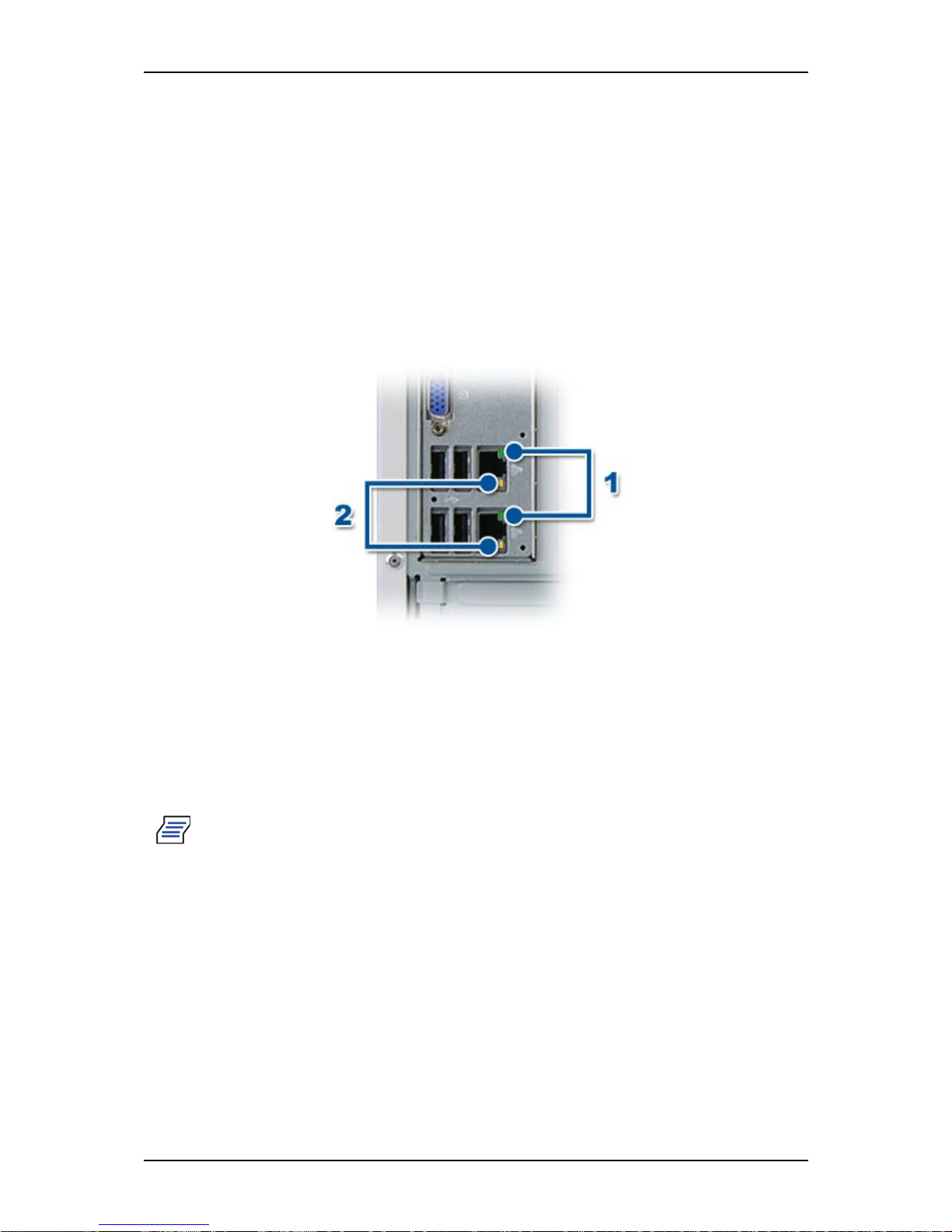
Network ports
Figure 7: Rear panel lamps
1. LINK/ACT lamp
This lamp indicates the state of each network port normally equipped with the
server.
Lights green: the server and the hub are correctly connected with each other
(LINK state).
Blinks green: information is transmitted through a network port (ACT state).
Note:
•
If the lamp does not light in the LINK state, check the network cable and
the cable connection.
• If the lamp still does not light, the network (LAN) controller may be
defective. Contact your service representative.
2. 1000/100/10 lamp
This lamp indicates whether each of the standard network ports is operated
through the 1000BASE-T, 100BASE-TX or 10BASE-T network interface.
Lights amber: the network port is operated through 1000BASE-T.
Lights green: the network port is operated through 100BASE-TX.
Off: the network port is operated through 10BASE-T.
Page 23
User Guide
23
www.bull.com
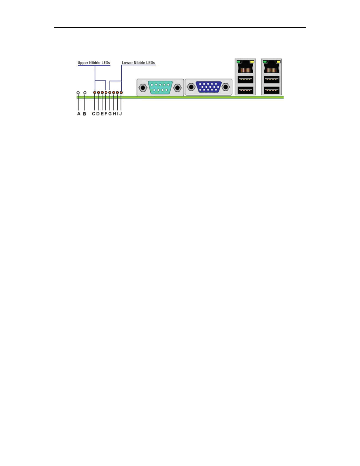
Diagnostic LEDs
Figure 8: Diagnostic LED Placement Diagram
Refer to “Diagnostic LEDs” on page 164 to check the meaning of LEDs status.
A. ID LED F. Diag nostic LED #4
B. Status LED G. Dia gnostic LED #3
C. Diagnostic LED #7 (MSB LED) H. Diagnostic LED #2
D. Diagnostic LED #6 I. Diagnostic LED #1
E. Diagnostic LED #5 J. Diagnostic LED #0 (LSB LED)
Page 24
User Guide
24
www.bull.com
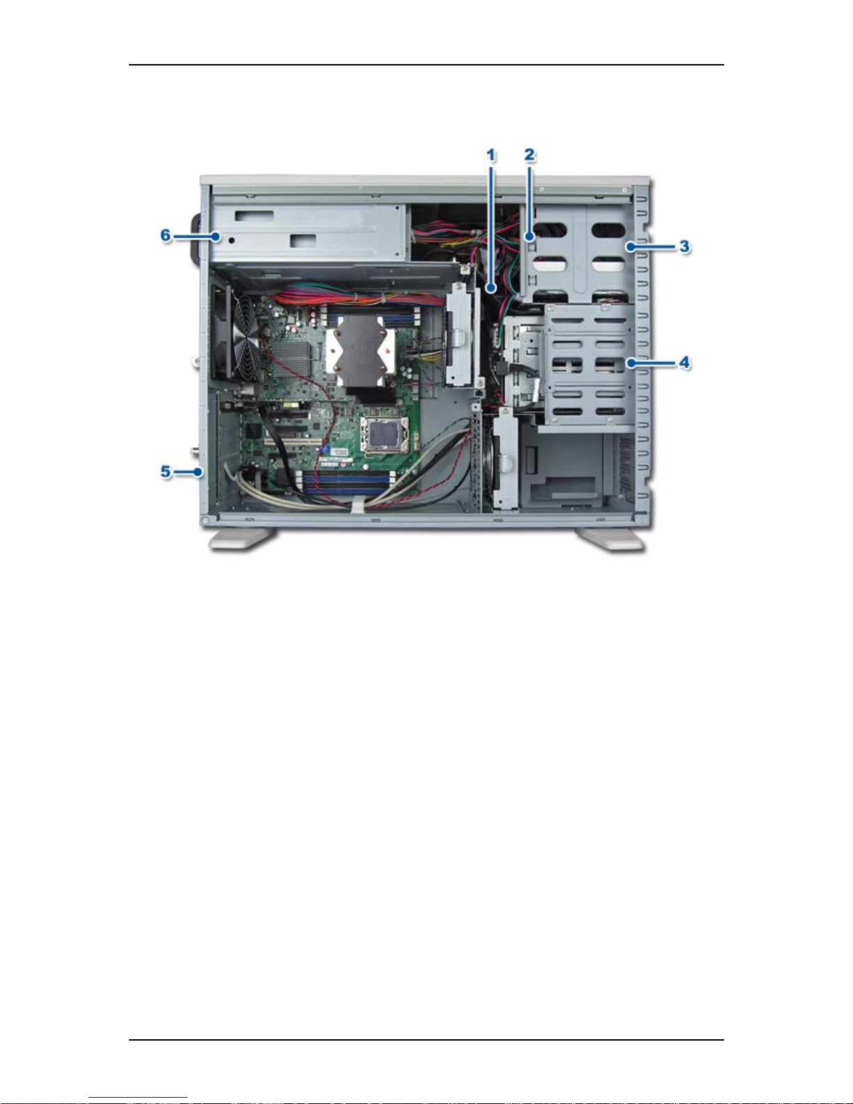
T840 E2 Internal View
Figure 9: Internal View
1. Air duct
2. Tool-less device bay locks
3. 5.5 inch device bay
4. Hard disk drive bay
5. Rear tool-less PCI retention mechanism
6. Power supply
Page 25
User Guide
25
www.bull.com
Motherboard
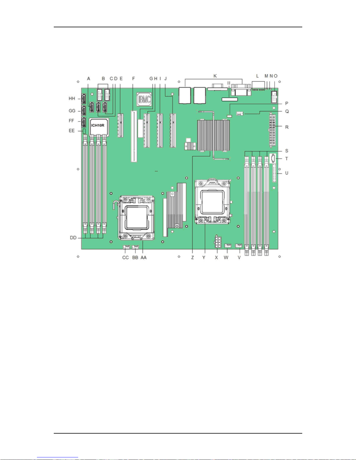
Motherboard Layout
Figure 10: Motherboard Layout
A SATA 3 J Slot 7, PCI Express* x8 S DIMM sockets off
Processor 1 socket
(Channel A, B)
BBCPU 2 Fan header
B Internal dual port USB2.0
header
K Back panel I/O ports T Power Supply Auxiliary
Connector
CCSystem Fan 1 header
C SATA 5 L Diagnostic LEDs U SSI 24-pin Front Panel
connector
DDDIMM sockets off
Processor 2 socket
(Channel D, E)
D SATA 4 M Status LED V System fan 2 header EESATA SGPIO
E Slot 3, PCI Express* x4 N ID LED W CPU 1 fan header FFSATA 0
F Slot 4, 32-bit/33 MHz PCI O External Serial B header X CPU Power Connector GGSATA 1
G Intel® RMM3 slot P SATA Key Y CPU Socket 1 HHSATA 2
H Slot 5, PCI Express* x8 Q System fan 3 header Z Intel® IOH 5500 chipset II Battery
I Slot 6, PCI Express* x8
(Riser card)
R Main power connector AACPU Socket 2
Page 26
User Guide
26
www.bull.com
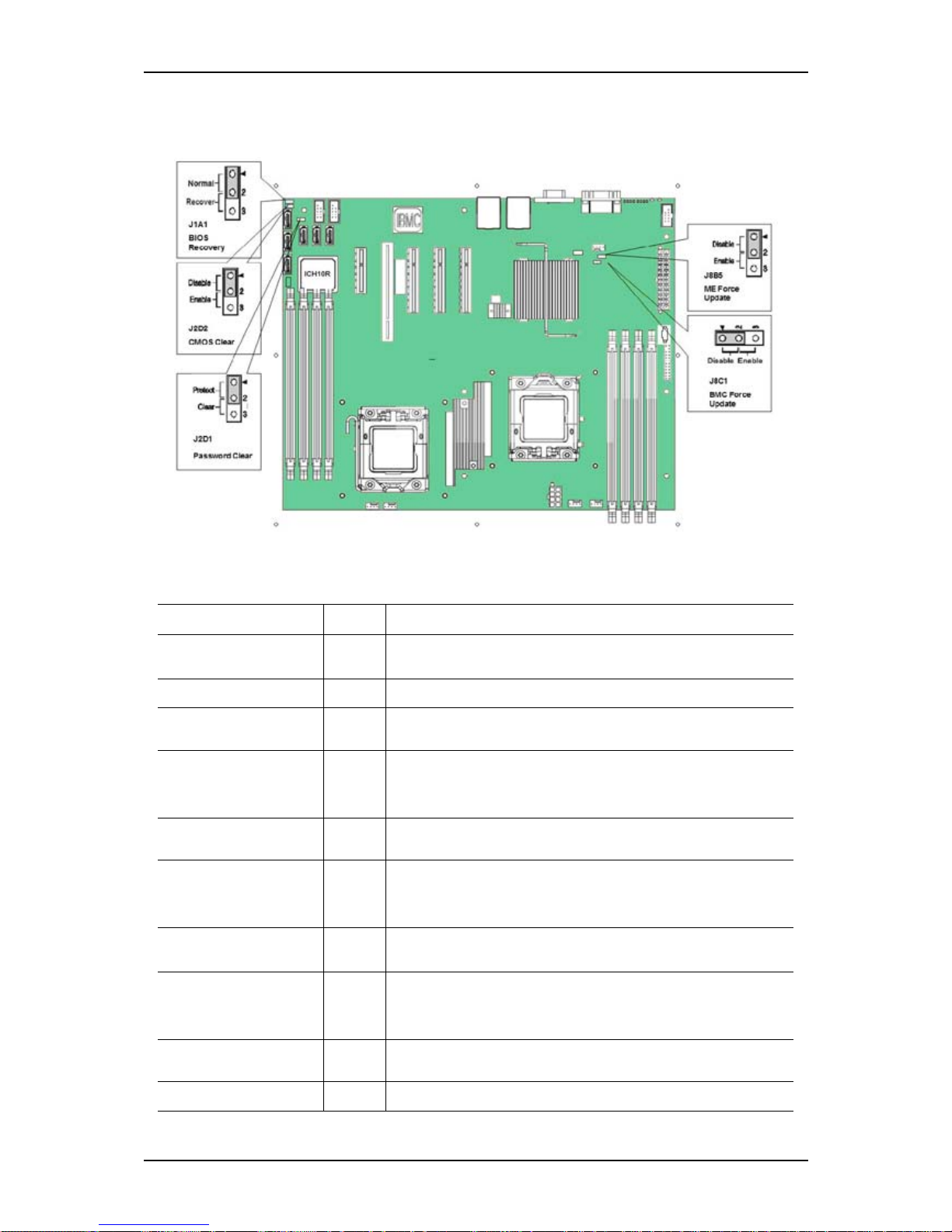
Motherboard Jumpers
Figure 11: Motherboard Jumpers
Table 1: Motherboard Jumpers Description
Jumper Name Pins Jumper Purpose
J8C1: BMC Force
Update
1-2
BMC Firmware Force Update Mode - Disabled (Default)
2-3 BMC Firmware Force Update Mode - Enabled
J2D1: Password Clear 1-2
These pins should have a jumper in place for normal system
operation. (Default)
2-3
If these pins are jumpered, the administrator and user passwords
are cleared on the next reset.
NOTE: These pins should not be jumpered for normal operation.
J2D2: CMOS Clear 1-2
These pins should have a jumper in place for normal system
operation. (Default)
2-3
If these pins are jumpered, the CMOS settings are cleared on the
next reset.
NOTE: These pins should not be jumpered for normal operation.
J1A1: BIOS Recovery 1-2
These pins should have a jumper in place for normal system
operation.(Default)
2-3
The main system BIOS will not boot with these pins jumpered.
NOTE: The system will boot from EFIbootable recovery media with
a recovery BIOS image.
J8B5: ME Force Update
1-2
These pins should have a jumper in place for normal system
operation. (Default)
2-3
ME force update model.
Page 27

User Guide
27
www.bull.com
Clearing the CMOS
If you are not able to access the BIOS setup screens, the CMOS Clear jumper will need
to be used to reset the configuration RAM. The CMOS Clear jumper is located on jumper
block J2D2 on the server boar
d.
Refer to “Motherboard Jumpers” on page 26 to locate the jumper.
1. Power down the system and disconnect the AC power.
2. Open the server.
3. Move the jumper from the normal operation position (pins 1 and 2) to pins 2
and 3 (Clear CMOS position).
4. Reconnect the AC power, power up the system.
5. When the system begins beeping, power it down and disconnect the AC power.
6. Replace the jumper on pins 1 and 2.
7. Close the server chassis.
8. Reconnect the AC power and power up the system.
Recovering the BIOS
The following steps boot the recovery BIOS and flashes the normal BIOS:
1. Power down and unplug the system from the AC power source.
2. Move the recovery jumper at JIA1 from the spare location at pins 1 and 2 to
cover pins 2 and 3.
Refer to
“Motherboard Jumpers” on page 26 to locate the jumper.
3. Insert the bootable BIOS Recovery media containing the new BIOS image
files.
You can accomplish a BIOS recovery from the SATA CD and USB Mass
Storage device.
Note: Recovery from a USB floppy is not supported on this platform.
The recovery media must contain the following files under the root directory:
■
FVMAIN.FV
■ UEFI iFlash32
■ *Rec.CAP
■ Startup.nsh (update accordingly to use proper *Rec.CAP file)
Page 28
User Guide
28
www.bull.com
4. Plug the system into the AC power source and power it on.
5. The BIOS POST screen appears.
6. When complete, remove the recovery media.
7. Power down and unplug the system from the AC power source.
8. Move the BIOS recovery jumper at J1A1 back to the original position,
covering storage pins 1 and 2.
9. Plug the system into the AC power source and power it up to confirm the
recovery is successful.
Note: Do NOT interrupt the BIOS POST during the first boot.
Note: for more information on the BIOS Update process, please refer to
“Updating the BIOS” on page 197.
Rear Panel Connectors
Refer to “T840 E2 Rear View” on page 21 for details.
Processor
The system board can accommodate the following:
- The Intel® Xeon® Nehalem-EP processors.
RAID Support
The Intel® Server Board provides six SATA ports (3 Gbps) via ICH10R with Intel®
Embedded Server RAID Technology, with SW RAID levels 0/1/10. Optional support
for SW RAID 5 with activation key.
The BIOS Setup utility provides multiple drive configuration options on the Advanced
Mass Storage Controller Configuration setup page, some of which affect the ability to
configure RAID. By default, the “Onboard SATA Controller” option is enabled. When
this option is enabled, you can set the “SATA Mode” option to the following modes,
which also lists how the mode affects configuration:
■ ENHANCED Mode: Supports up to six SATA ports with IDE Native Mode.
■ COMPATIBILITY Mode: Supports up to four SATA ports[0/1/2/3] with IDE
Legacy mode and two SATA ports[4/5] with IDE Native Mode.
■ AHCI Mode: Supports all SATA ports using the Advanced Host Controller
Interface (AHCI) when the option is enabled.
Note: For AHCI capability in EFI, you must set the AHCI legacy Option
ROM to “disabled”.
■ SW RAID Mode: Supports configuration of SATA ports for RAID using RAID
configuration software.
Refer to the “Advanced Menu” on page 174 for more information on how to select the
controller that will be active in your system.
Page 29
User Guide
29
www.bull.com
Set-up with the Intel Matrix Storage Manager configuration utility. Refer to “RAID
Configuration using Matrix Storage Manager” on page 78.
Refer to “LSI 8708EM2 SAS/SATA RAID Controller” on page 46 for more
information.
Memory Configuration
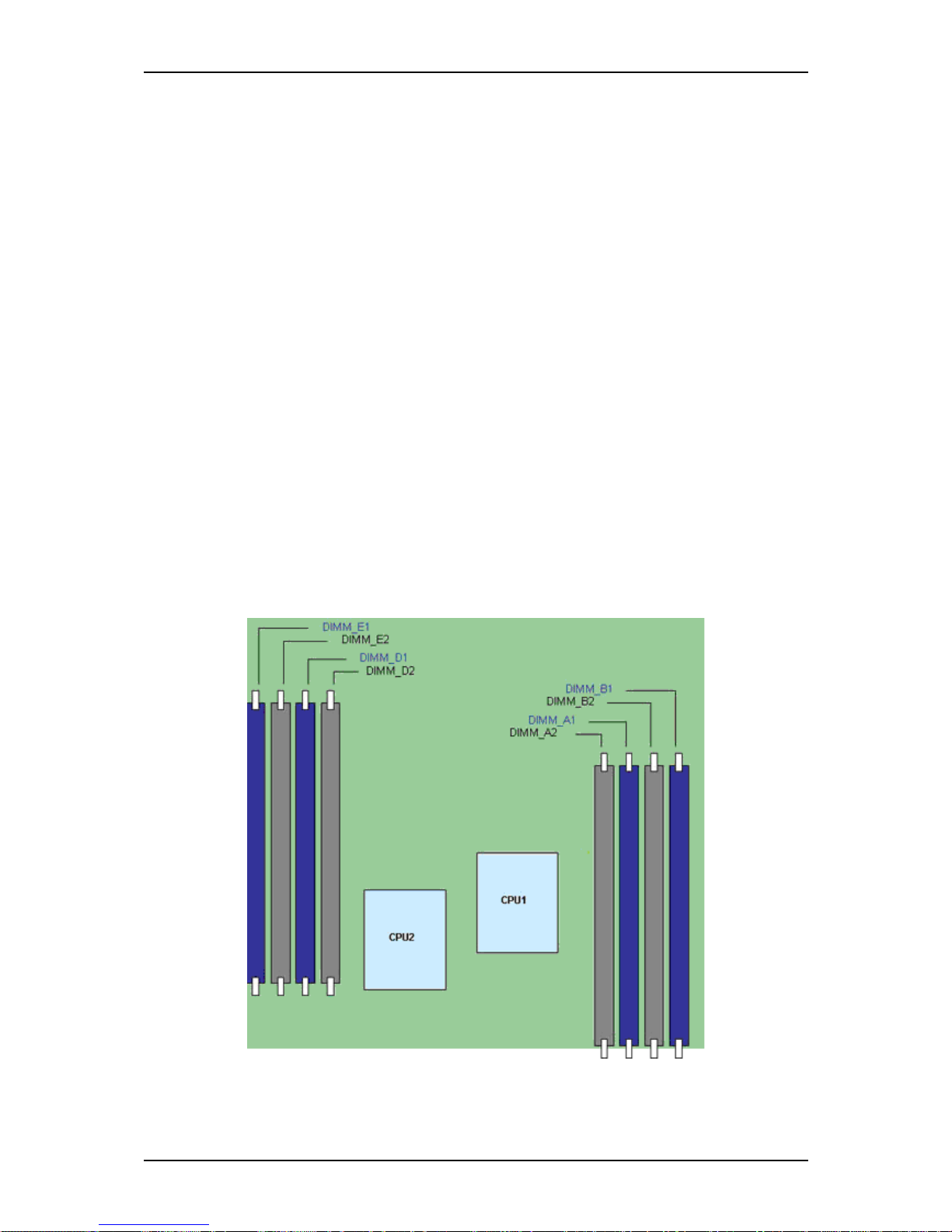
The Intel® Server Board S5500BC supports a DDR3-based memory subsystem. The server
board supports two DIMMs per channel. The silkscreen on the board for the DIMMs
displays:
■ DIMM_A1
■ DIMM_A2
■ DIMM_B1
■ DIMM_B2
■ DIMM_D1
■ DIMM_D2
■ DIMM_E1
■ DIMM_E2
The minimal population possible is DIMM_A1.
Figure 12: DIMM Configuration Diagram
Page 30
User Guide
30
www.bull.com
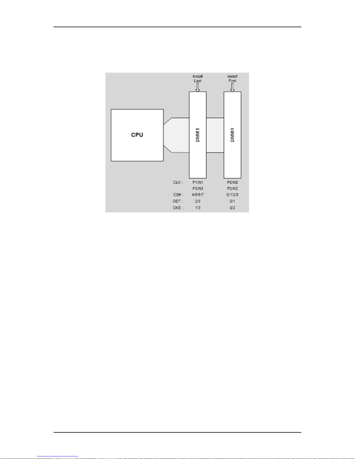
For two slots per channel configuration, the server board requires DDR3 DIMMs
within a channel to be populated starting with the DIMM farthest from the processor.
See below figure “Channel Slots Configuration” on page 30.
Figure 13: Channel Slots Configuration
The Independent Channel Mode is the default Maximum Performance Mode preferred
for Intel® Xeon® 5500 proc essor series based platforms. You can populate all two channels in
any order and have no matching requirements. All channels must run at the same
interface frequency, but individual channels may run at different DIMM timings (RAS
latency, CAS latency, and so forth).
Memory Sparing and Mirroring
The spare mode is not supported by the Intel® Server Board S5500BC. With memory
mirroring, the system maintains two copies of all data in the memory subsystem. If a
DIMM fails, the data is not lost because the second copy of the data is available from
the mirrored DIMM in the opposite channel. The system will not fail due to memory
error unless both the primary and the mirrored copy of the data become corrupt at the
same time.
In a mirrored system, the maximum usable memory is one-half of the installed memory
with a minimum of two DIMMs installed. Since the data is duplicated across DIMMs,
it means that up to one-half of the installed DIMMs are actively in use at any one time.
The remaining DIMMs are used for mirroring.
BMC Controller
The Integrated Baseboard Management Controller (Integrated BMC) is a highly
integrated single-chip solution, incorporating several devices typically found on
servers. The Integrated BMC on the Intel® Server Board S5500BC contains the
following integrated functionality subsystem:
Page 31

User Guide
31
www.bull.com
Server Class Super I/O functionality includes:
- Keyboard Style/BT interface for BMC support
- One Fully Functional Serial Ports, compatible with the 16C550
- Serial IRQ Support
- SMI/SCI/PME Support
- ACPI Compliant
- Up to 16 Shared GPIO ports
- Programmable Wake-up Event Support
- Plug and Play Register Set
- Power Supply Control
- Watchdog timer compliant with Microsoft SHDG
- LPC to SPI bridge for system BIOS support
- Real Time Clock module with the external RTC interface
Baseboard Management Controller
- IPMI 2.0 Compliant
- Integrated 250Mhz 32-bit ARM9 processor
- Six I2C SMBus Modules with Master-Slave support
- Two independent 10/100 Ethernet Controllers with RMII support
SPI Flash interface
- Three UART for ICMB support
- DDR-II 16bit up to 667 MHz memory interface
- Sixteen Mailbox Registers for communication between the host and the BMC
- Watchdog timer
- Three General Purpose Timers
- Dedicated Real Time Clock for BMC
- Up to 16 direct and 64 Serial GPIO ports
- Ability to maintain text and graphics controller history
- 12 10-bit Analog to Digital Converters
- Three Diode Inputs for Temperature measurements
- Eight Fan Tach Inputs
- Four Pulse Width Modulators (PWM)
- Chassis Intrusion Logic with battery backed general purpose register
Page 32

User Guide
32
www.bull.com
- LED support with programmable blink rate control
- Programmable IO Port snooping, can be used to snoop on Port 80h
- Unique Chip ID for each part, burned at the time production testing
- Hardware 32-bit Random Number generator
-JTAG Master interface
- On-Chip Test Infrastructure for testing BMC firmware
Remote KVMS Features
- USB 2.0 interface for Keyboard, Mouse and Remote storage such as CD/DVD
ROM and floppy
- USB 1.1 interface for PS2 to USB bridging, remote Keyboard and Mouse
- Hardware Based Video Compression and Redirection Logic
- Supports both text and Graphics redirection
- Hardware assisted Video redirection using the Frame Processing Engine
- Direct interface to the Integrated Graphics Controller registers and Frame buffer
- Hardware based encryption engine
Graphics Controller Subsystem
- Integrated Matrix Graphics Core
- 2D Hardware Graphics Acceleration
- DDR-II memory interface supports up to 128Mbytes of memory
- Supports all display resolutions up to 1600 x 1200 16bpp @ 75Hz
- High speed Integrated 24-bit RAMDAC
- Single lane PCI-Express host interface
Video
The Intel® server board S5500BC includes a video controller in the on-board
ServerEngines* LLC Pilot II BMC, as well as 64 MB of video DDR2 SDRAM.
The SVGA sub-system supports a variety of modes, up to 1600 x 1200 resolution in 8/
16/32 bpp, under 2D.
It also supports both CR T and LCD monitors up to a 100-Hz vertical refresh rate. Video
is accessed using a standard 15-pin VGA connector on the back edge of the server
board.
Network Controller
Note: To ensure EMC product regulation compliance, the system must be
used with a shielded STP/FTP LAN cable.
Page 33

User Guide
33
www.bull.com
The Intel® 82574L GbE PCI-E Network Controller is a single, compact component
with integrated Gigabit Ethernet Media Access Controller (MAC) and Physical Layer
(PHY) function.
This device is connected to the Intel® ICH10R. The Intel® Server Board S5500BC
uses this device along with the integrated Intel® ICH10R MAC and external Intel®
82567 Gigabit Network connector to provide two Gigabit Ethernet Ports designed for
10/100/1000 Mbps operation.
The Intel® 82574L GbE PCI-E Network Controller is correlated to NIC2 connector on
the back edge of the board, the external Intel® 82567 Gigabit Network is correlated to
NIC1 connector on the back edge of the board.
Refer to “Diagnostic LEDs” on page 23 to see network controllers LEDs meaning.
ACPI
The motherboard supports the Advanced Configuration and Power Interface (ACPI) as
defined by the ACPI 2.0 specifications. An ACPI aware operating system can put the
system into a state where the hard drives spin down, the system fans stop, and all
processing is halted. However, the power supply will still be on and the processors will
still be dissipating some power, so the power supply fans will still run.
The system board supports sleep states s0, s1, s4, and s5:
■ s0: Working state.
■ s1: Processor sleep state. No context will be lost in this state and the processor
caches will maintain coherency.
■ s4: Hibernate state. Your working environment is Saved To Disk
■ s5: Shutdown.
Keyboard and Mouse
The keyboard/mouse controller is USB-compatible.
Page 34

User Guide
34
www.bull.com
Page 35

User Guide
35
www.bull.com
Optional Features
You will find hereafter information about the optional components that may be
installed in your system.
This is not an exhaustive list, some options may not be available any more, others may
have been added.
Page 36

User Guide
36
www.bull.com
DVD Writer Combination Drive
■ Form Factor: 5.25" half height with Serial ATA interface
■ The drive is capable to write 12xPCAV speed DVD-RAM (Ver. 2)writing
- Random and Sequential.
20xCAV speed DVD+R writing and 12xZCLV speed DVD+R DL writing and
8xZCLV speed DVD+RW writing
- Random, Sequential and Multi-Session.
20xCAV speed DVD-R writing and 12xZCLV speed DVD-R DL writing and
6xCLV speed DVD-RW writing and 2xCLV speed DVD-RW DL writing
- Disc at Once, Incremental, and Multi-Border. Restricted overwrite (DVD-RW
only)
48xCAV speed CD-R writing and 32xZCLV speed CD-RW writing- Supports
various DVD and CD formats.
■ Power tray disc loading mechanism.
■ The drive can be mounted and used in both horizontal and vertical orientation.
■ Disc Diameter 120mm or 80mm
■ Busy LED.
■ Data buffer: 2MB
Caution: After burning a DVD, we recommend you wait 10 minutes before
burning another one.
Page 37

User Guide
37
www.bull.com
DAT72 Tape Backup Unit (USB)
Please refer to the documentation on the Tape Online CD for more information.
Page 38

User Guide
38
www.bull.com
DAT160 Tape Backup Unit (USB)
Please refer to the documentation on the Tape Online CD for more information.
Page 39

User Guide
39
www.bull.com
LTO-3 HH Tape Drive (SCSI)
Please refer to the documentation on the Tape Online CD for more information.
Page 40

User Guide
40
www.bull.com
LTO-4 HH Tape Drive (SAS)
Please refer to the documentation on the Tape Online CD for more information.
Page 41
User Guide
41
www.bull.com
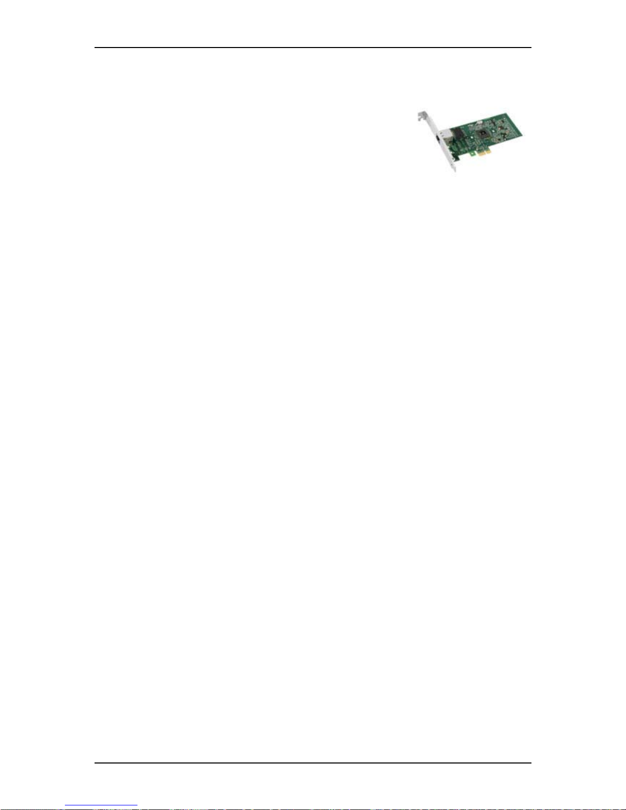
Intel Pro/1000 PT Single Port LAN Board
One gigabit copper server connection in a PCI Express slot.
Interface
■ PCI Express.
Connectors
■ One RJ-45.
IEEE standards / network topology:
■ 10BASE-T, 100BASE-TX, 1000BASE-T.
Features
■ High-performance, self-configuring 10/100/1000 Mbps connection for PCI
Express slots
■ Multi-Gigabit scalability and increased uptime through advanced server features
■ Load balancing on multiple CPUs: Increases performance on multi-processor
systems by efficiently balancing network loads across CPU cores.
■ Interrupt moderation: Delivers increased performance while significantly reducing
CPU utilization.
■ Compatible with x1, x4, x8, and x16 full-height and low-profile PCI Express slots.
■ Remote management support.
■ Intel® PROSet Utility for Microsoft Device Manager: Provides point-and-click
power over individual adapters, advanced adapter features, connection teaming,
and VLAN configuration.
■ Advanced cable diagnostics: Dynamically tests and reports network problems
(error rate, cable length) and automatically compensates for cable issues (crossover cable, wrong pin-out/polarity).
Page 42
User Guide
42
www.bull.com
Intel Pro/1000 PT Dual Port LAN Board
Two gigabit copper server connections in a single PCI
Express slot.
Interface
■ PCI Express.
Connectors
■ Two RJ-45.
IEEE standards / network topology:
■ 10BASE-T, 100BASE-TX, 1000BASE-T.
Features
■ Intel® PROSet Utility and Intel® PRO Intelligent Install for easy installation.
■ Intel® lead-free1 technology.
■ Plug and play specification support Standard.
■ Auto-negotiation, full-duplex capable.
■ Integrated media access control (MAC) and physical layer (PHY).
■ Includes a full-height bracket.
■ Cable distance: 100m in Category-5 for 100/1000 Mbps and Category-3 for 10
Mbps.
Network Management
■ Wired for Management (WfM) baseline v2.0 enabled for servers.
■ DMI 2.0 support, Windows Management Instrumentation (WMI) and SNMP-
manageable SMBus support.
■ Remote Installation Services (RIS).
■ Diagnostics (loopback, testability, PHY register access).
■ Advanced Configuration and Power Interface (ACPI) 1.0 power management.
■ Wake on LAN support over PCI Express.
■ PXE 2.0 enabled through boot read-only memory (ROM).
Advanced Software Features
■ Adapter Fault Tolerance (AFT).
■ Switch Fault Tolerance (SFT).
■ Adaptive Load Balancing (ALB).
■ Fast EtherChannel (FEC).
Page 43

User Guide
43
www.bull.com
■ Gigabit EtherChannel (GEC).
■ Teaming support : Scales up to 8 connections.
■ Multiple teams: Supports 4 separate teams, maximum.
■ IEEE 802.3ad (link aggregation control protocol).
■ PCIe Hot Plug/Active peripheral component interconnect (PCI).
■ IEEE 802.1Q VLANs.
■ IEEE 802.3 (z, ab, u, x) flow control support.
■ TCP checksum offload — transmission control protocol (TCP), user datagram
protocol (UDP), Internet protocol (IP).
■ IEEE 802.1p.
■ TCP segmentation/large send offload.
■ Interrupt moderation.
Page 44

User Guide
44
www.bull.com
S-ATA Hard Disk Drive
■ SATA II specification.
■ Capacity: 160GB minimum on 2.5”; 250GB minimum on3.5”
■ 7200 RPM
■ RAID support
Page 45

User Guide
45
www.bull.com
SAS Hard Disk Drive
■ Capacity: 73GB minimum on 2.5”; 300GB minimum on 3.5”
■ 10000 or 15000 RPM
■ RAID support
Page 46
User Guide
46
www.bull.com
LSI 8708EM2 SAS/SATA RAID Controller
Features
■ 8 SAS/SATA compatible ports
■ Optional battery backup module
■ Optional RAID5/6 key activation
■ Connect up to 16 intermixed SAS
and SATA devices within the
same array
■ Auto-resume on array rebuild
■ Auto resume array reconstruction
■ Online Capacity Expansion
■ Comprehensive management tools
■ Audible alarm circuit
Specifications
■ Hardware Specifications:
- LSI SAS 1078 RAID Chip
- PCI Express compliant.
- 3 Gb/s per lane.
- x8 lane width.
- Cache memory of 128MB or 256MB DDRII 667MHz SDRAM (depending on
your configuration).
■ RAID Support:
- RAID Levels 0, 1, 10.
- RAID Levels 0, 1, 10, 5, and 6 with the optional activation key.
Note: For more information, refer to the documentation included on the
ExpressBuilder DVD-ROM.
Page 47
User Guide
47
www.bull.com
Adaptec SCSI Card 29320LPE
This card is a PCIe x1 Ultra320 SCSI controller that
is ideal as a SCSI tape drive connection solution
thanks to its unparalleled PCIe connectivity, and the
reliability and stability of a single-channel I/O
interface.
Features
■ Interface: PCIe x1
■ Data transfer rate: up to 320Mbyte/sec.
■ Connectors:
- Internal: One 68-pin VHDCI
- External: One 68-pin Ultra320
■ Physical Specifications
- Size: 16,8cm x 6,5cm
Note: no internal SCSI tape drive is qualified for your system.This card is
used only to connect to external storage devices.
Note: refer to the Card User Guide for more information.
Page 48
User Guide
48
www.bull.com
LSI SAS 3442E-R
The LSI SAS3442E-R four-port internal/four-port
external SAS/SATA PCI Express storage adapter
provides 300 MB/s bandwidth (600 MB/s, full
duplex) on each port for combined throughput of up
to 2.4 GB/s.
The storage adapter supports multi-volume OS
independent Integrated RAID 0, 1, 1E and 10E
without the need for special drivers. The
SAS3442E-R features PCI Express connectivity, removing the host bus bottleneck
from the parallel PCI busses.
Features
■ 3Gb/s per port
■ x4 internal SFF-8484 / x4 external SFF-8470 connectors
■ Integrated RAID 0, 1, 1E and 10E
■ 8-lane 2.5 Gb/s PCI Express
■ MD-2 small form-factor design
■ Connects to both SAS and SATA HDDs and tape drives
■ Allows more than 122 total end-point devices
■ Fusion-MPT architecture provides more than 140,000 I/Os per second
Note: refer to the Card User Guide for more information.
Page 49

User Guide
49
www.bull.com
Setting Up Your System
This chapter describes how to select a site, unpack the system, make cable connections,
and power on the system units. Information on front and rear panel features, switches
and LEDs are also included in this chapter.
Page 50

User Guide
50
www.bull.com
Unpacking the System
When you receive your system, inspect the shipping containers prior to unpacking. If
the shipping boxes are damaged, note the damage, and if possible, photograph it for
reference.
Remove the contents of the containers, and keep the cartons and the packing materials.
If the contents appear damaged when you unpack the boxes, file a damage claim with
the carrier immediately.
The carton contains various accessories, as well as the system itself. If you find any
component missing or damaged, contact your service representative.
Store the provided accessories in a designated place for your convenience. You will
need them to install an optional device or troubleshoot your system, as well as to set it
up.
Make a backup copy of each provided discs, if any. Store the original disc as the master
disc in a designated place, and use its copy.
Improper use of any provided disc may alter your system environment. If you find
anything unclear, immediately ask your service representative for help.
Page 51
User Guide
51
www.bull.com
T840 E2 Rack Conversion Kit Assembly
This section provides the assembly instructions for mounting the server into a standard
19-inch rack cabinet.
Unpacking the Rack Conversion Kit
Although the rack installation kit is inspected and carefully packaged at the factory,
damage may occur during shipping. Follow these steps for unpacking.
1. V isually inspect the shipping containers; notify your carrier immediately of any
damage.
2. Carefully remove the rack mounting hardware and verify the parts.
Note: The quantities noted below are subject to change without notice.
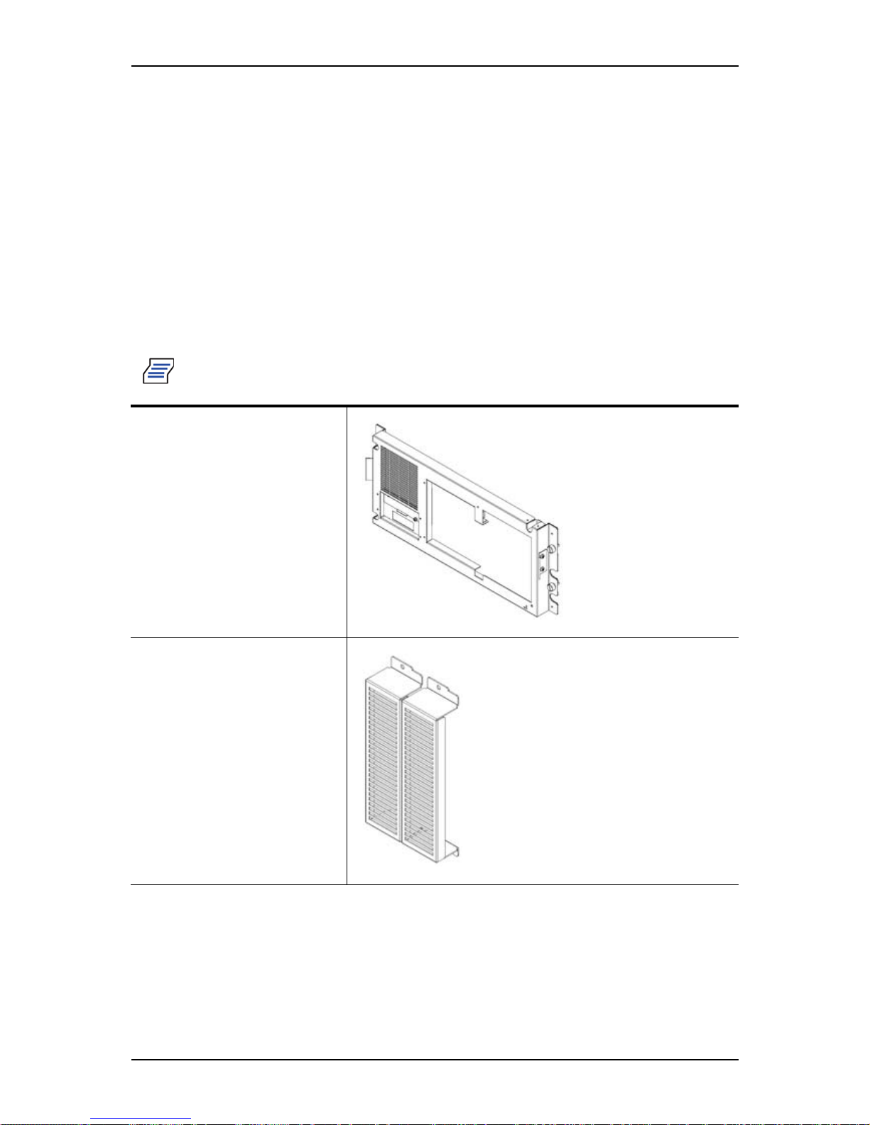
Front cover
1 unit
Device cover
2 units
Page 52
User Guide
52
www.bull.com
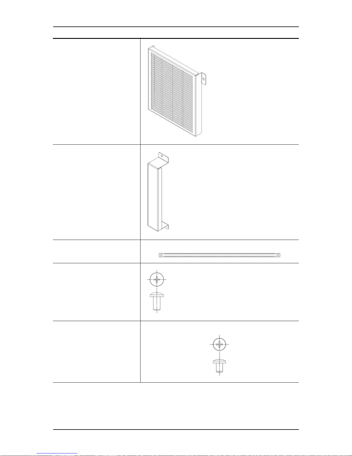
3.5 inch HDD cover
1 unit
2.5 inch blank cover
1 unit
Filler
1 unit
Metric Screw (M5)
10 units
Inch screw (#6-32UNC)
5 units
Page 53
User Guide
53
www.bull.com
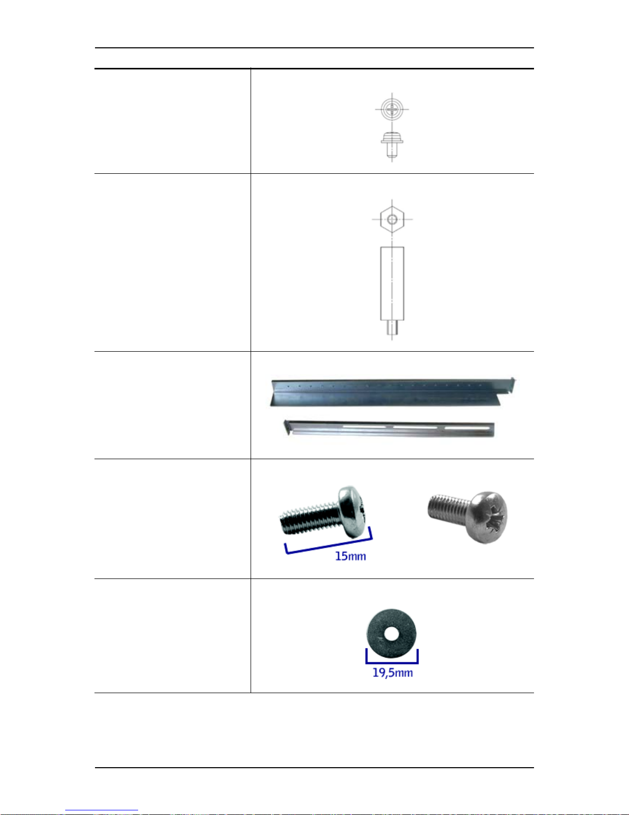
Metric screw (M4)
14 units
Stud
1 unit
2 sets of support rail assem-
blies (1 front and 1 rear part
for each)
6 (minimum) self-tapping
screws (TCB M5) for support
rails front and rear parts
assembling
6 (minimum) washers, to be
used with the 6 self-tapping
screws
Page 54
User Guide
54
www.bull.com
If some of the parts listed above are missing or if the hardware is damaged, notify your
server representative.
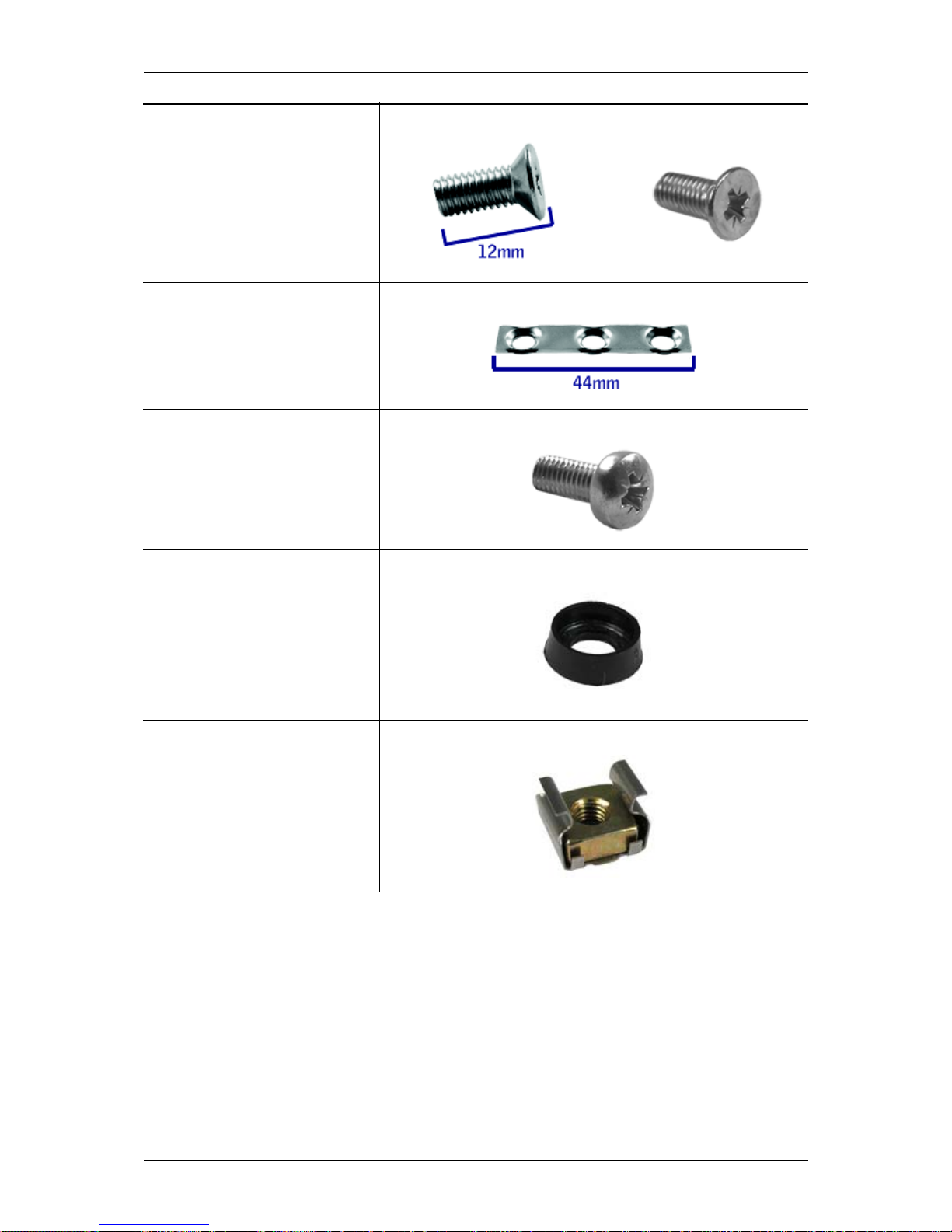
8 flange head screws (M5x12)
used to fix the support rail
assemblies to the rack
4 washer plates, to be used
with the flange head screws to
fix the support rail assemblies
to the rack
2 Screws M5x16, to be used
with the washers to fix the
filler to the mounting rails
2 Washers for the M5x16
screws
6 Caged nuts
2 units, to be used with the
screws and washers to fix the
filler to the mounting rails.
4 units, to fix the front bezel.
Page 55
User Guide
55
www.bull.com
Additional Parts for Future Use
Before You Begin
Before you begin, please review the following cautions, warnings, and general
guidelines.
Warning: Be sure that power to the system is turned off and unplugged.
All voltage is removed only when the power cords are unplugged.
■ Avoid excessive vibration and shock. Dropping an electronic component can cause
serious damage.
■ Do not disconnect or remove parts other than those specified in the procedure.
■ Do not touch I/O connector pins.
■ All screws are Phillips-head, unless otherwise specified.
■ On completion of any assembly or reassembly, perform a power-on test. If a fault
occurs, verify that the assembly or reassembly was performed correctly. If the
problem persists, refer to “Solving Problems” on page 148.
Static Precautions
An electrostatic discharge (ESD) can damage disk drives, option boards, and other
components. You can provide some ESD protection by wearing an anti-static wrist
strap attached to chassis ground when handling system components.
Electronic devices can be easily damaged by static electricity. To prevent damage, keep
them in their protective packaging when they are not installed in your system.
Assembly
The following subsection describes how to assemble your rack-mount server into a
standard 19-inch rack cabinet.
Before you begin select an appropriate location in your rack cabinet for the rack-mount
server. To improve rack stability, mount heavier items towards the bottom of the rack
cabinet. If the rack is a stand-alone unit and the rack is more than 75% filled with
components, consider installing an optional stabilizer kit.
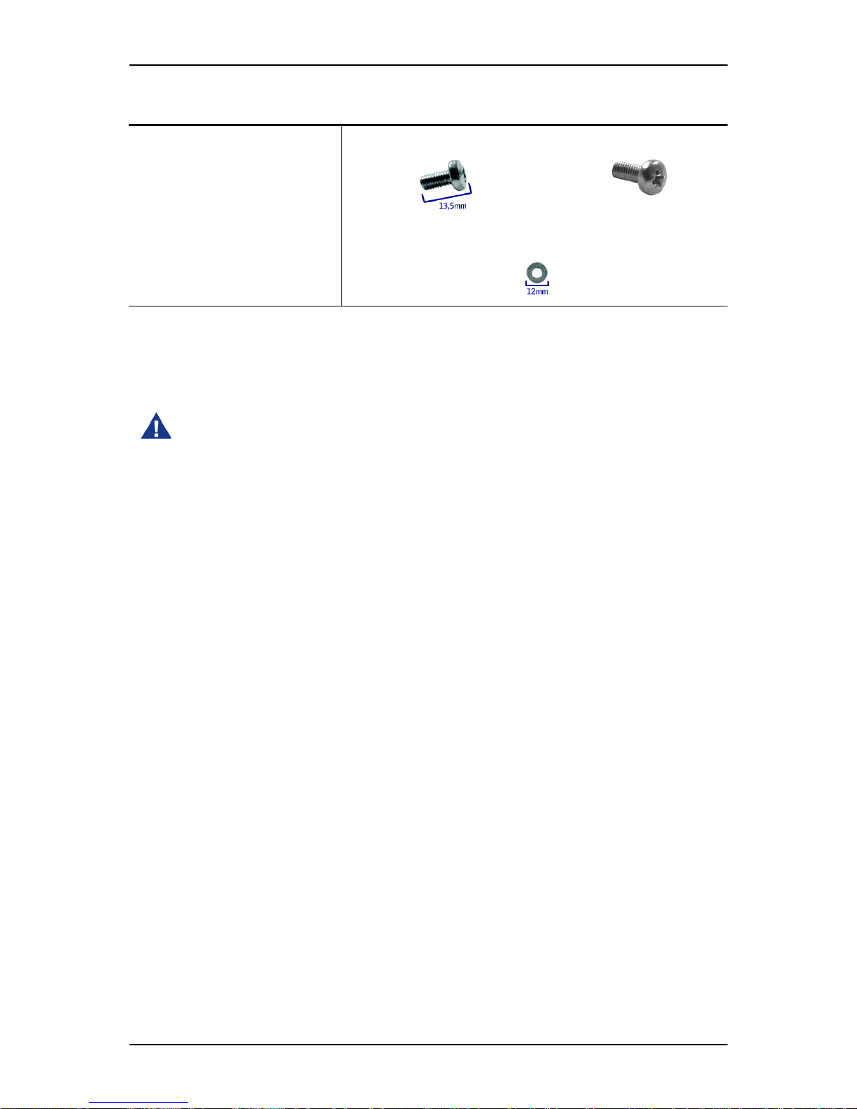
8 (minimum) screws TCB M5
8 (minimum) washers
Page 56
User Guide
56
www.bull.com
Caution: When planning your system configuration for the rack cabine t you should
consider the length of the cables that interconnect system components.
• Anchor the equipment rack: The equipment rack must be anchored to
an unmovable support to prevent it from falling over when one or more
servers are extended in front of it on slide assemblies. The anchors must
be able to withstand a force of up to 113 kg (250 lbs). You must also
consider the weight of any other device installed in the rack.
• Main AC power disconnect: You are responsible for installing an AC
power disconnect for the entire rack unit. This main disconnect must be
readily accessible, and it must be labelled as controlling power to the
entire unit, not just to the server(s).
• Grounding the rack installation: To avoid the potential for an electrical
shock hazard, you must include a third wire safety grounding conductor
with the rack installation. If a server power cord is plugged into an AC
outlet that is part of the rack, then you must provide proper grounding
for the rack itself. If server power cords are plugged into wall AC
outlets, the safety grounding conductor in each power cord provides
proper grounding only for the server. You must provide additional,
proper grounding for the rack and other devices installed in it.
• Temperature: The operating temperature of the server, when installed
in an equipment rack, must not go below 5 °C or rise above 35 °C.
Extreme fluctuations in temperature can cause a variety of problems in
your server.
• Ventilation: The equipment rack must provide sufficient airflow to the
front of the server to maintain proper cooling. It must also include
ventilation sufficient to exhaust a maximum of 4,100 Btu's per hour for
the server. The rack selected and the ventilation provided must be
suitable to the environment in which the server will be used.
Note: For vertical reference, every three screw holes on the rack vertical mounting
rail are equal to 1U (1.75 inches).
Mounting holes in the vertical rails of equipment racks are commonly spaced
in a 5/8 x 5/8 x 1/2-inch sequence. Perform the following steps carefully;
brackets must be mounted with precision to allow room for the next server
you install in a rack.
Page 57
User Guide
57
www.bull.com
Modifying the server from tower to rack-mount type
1. Remove the front bezel.
2. Remove the four stabilizers from the bottom of the server (4 screws).
Figure 14: Removing the stabilizers
3. Mount the stud to the front face of the server.
4. Using the screws securing the dummy cover mounted on the vacant slot of
5.25-inch device, put the device cover over the dummy cover, and secure it
together with the dummy cover.
Figure 15: Mounting the dummy cover
5. According to your system configuration, secure the 3.5-inch HDD cover to the
front cover with metric screw (M4).
■ 3.5-inch fixed disk model
Page 58
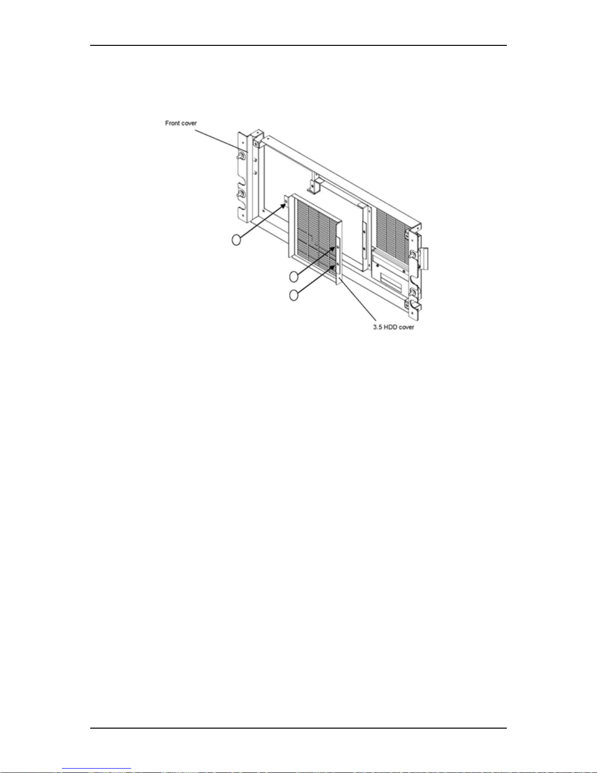
User Guide
58
www.bull.com
■ 3.5 HDD cover
■ 3 metric screws (M4)
Figure 16: Securing the HDD cover
Page 59
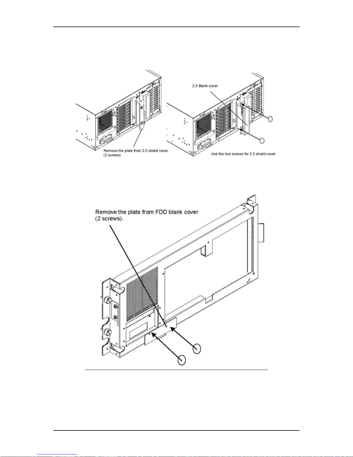
User Guide
59
www.bull.com
■ 2.5-inch disk model
■ 2.5 blank cover
Figure 17: Securing the 2.5 inch cover
■ Built-in FDD model
Figure 18: Removing the plate
Page 60
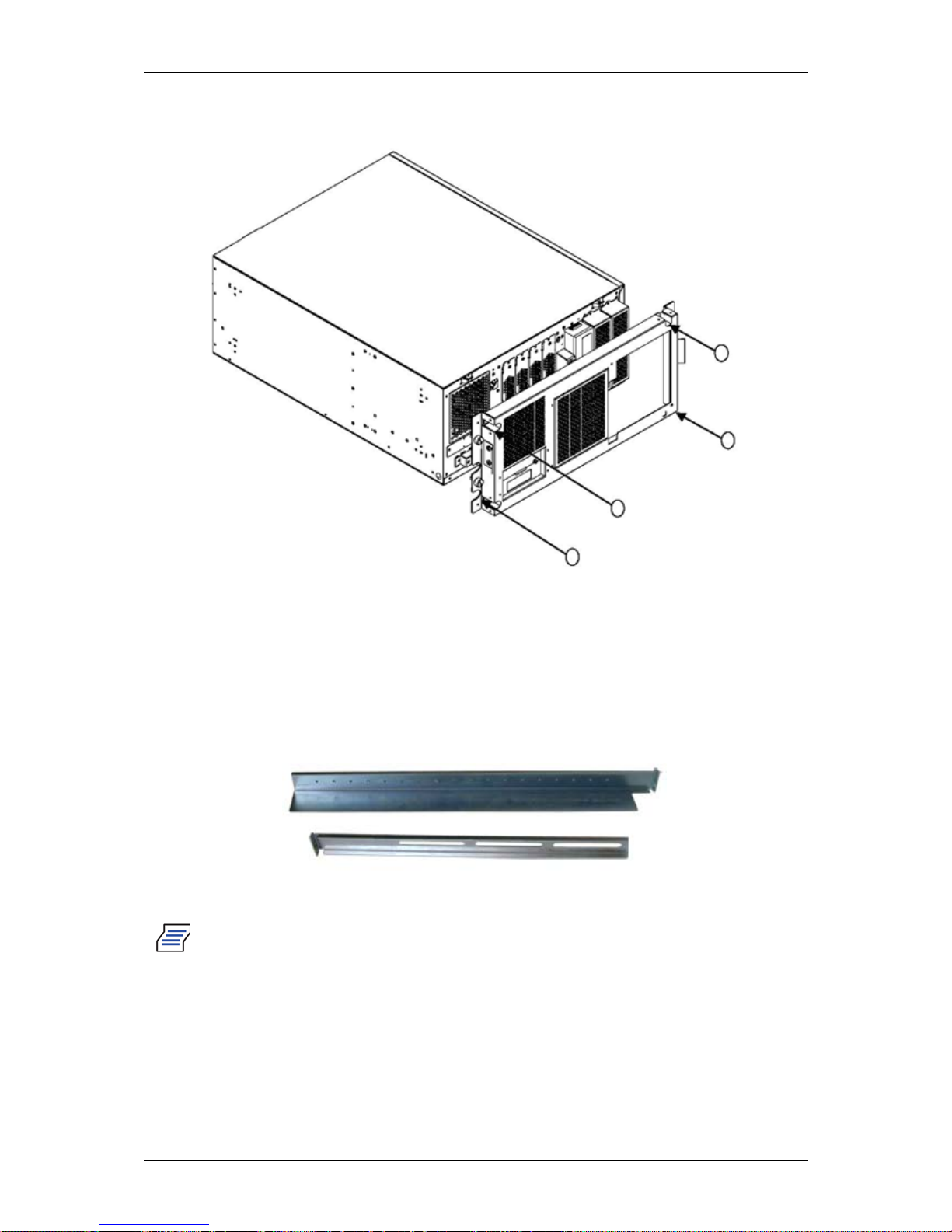
User Guide
60
www.bull.com
6. Fix the front cover with four inch screws (#6-32UNC).
Figure 19: Fixing the front cover
Assembling the Front and Rear Parts of Support Rails
The support rails are made of a front and a rear part. Those two parts may be adjusted
to fit the distance between the front and rear vertical rails of the rack.
1. Assemble the front and rear parts of the right support rail with 3 self tapping
screws and 3 flat washers.
Figure 20: Right support rail, front and rear parts
Note: When using self-tapping screws, we recommend you tighten the screw
for 3 quarters of a turn, and loosen for 1 quarter. Repeat this cycle until the
screw is completely tightened.
2. Adjust the total length to fit the distance between the front and rear vertical
rails of the rack before securing the screws.
3. Assemble the left support rail the same way.
Page 61
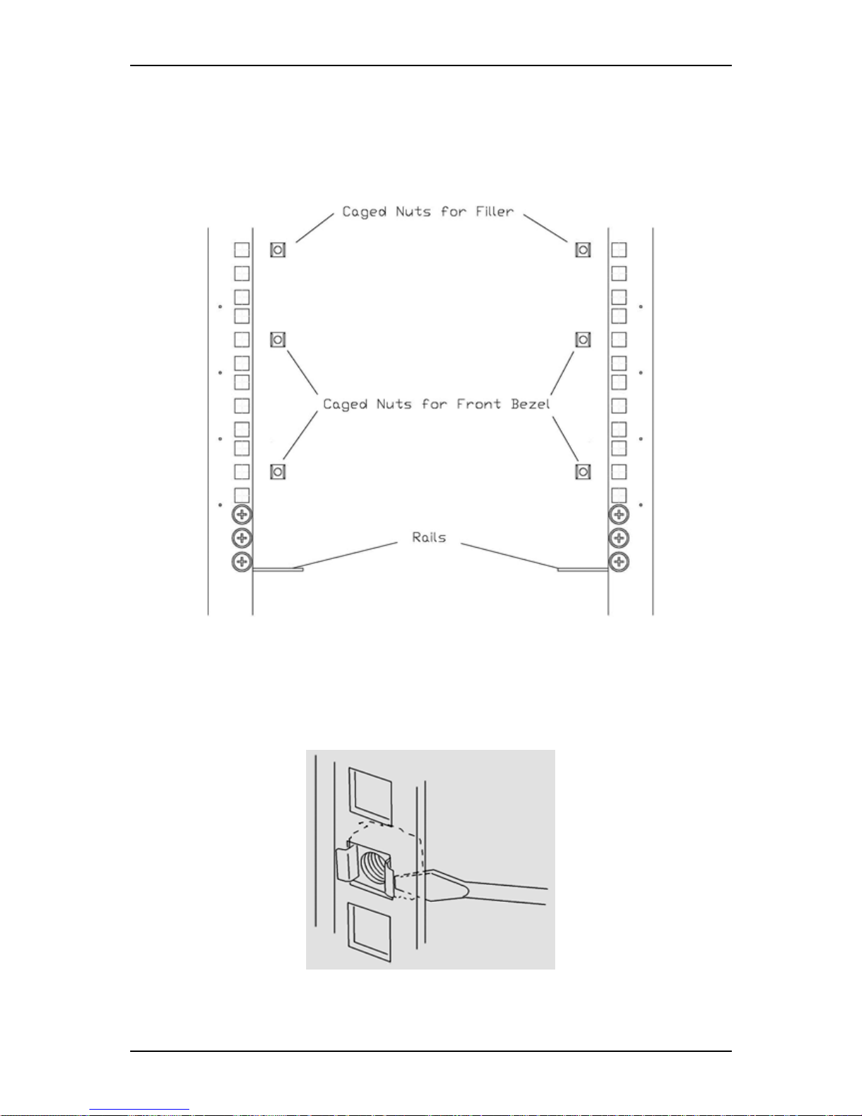
User Guide
61
www.bull.com
Installing the server in the rack
1. Install the right support rail in the rack.
2. Secure the rail to the front and rear vertical mounting rails with 3 flange head
screws M5 and the washer plate.
Figure 21: Installing the right support rail
■ Position the caged nut on the inside of the front vertical mounting rail.
■ Hook the side lip of a caged nut into the square hole in the rail.
■ Push the other side lip of the caged nut into the square hole in the rail
until it is secured.
Figure 22: Inserting a caged nut
Page 62
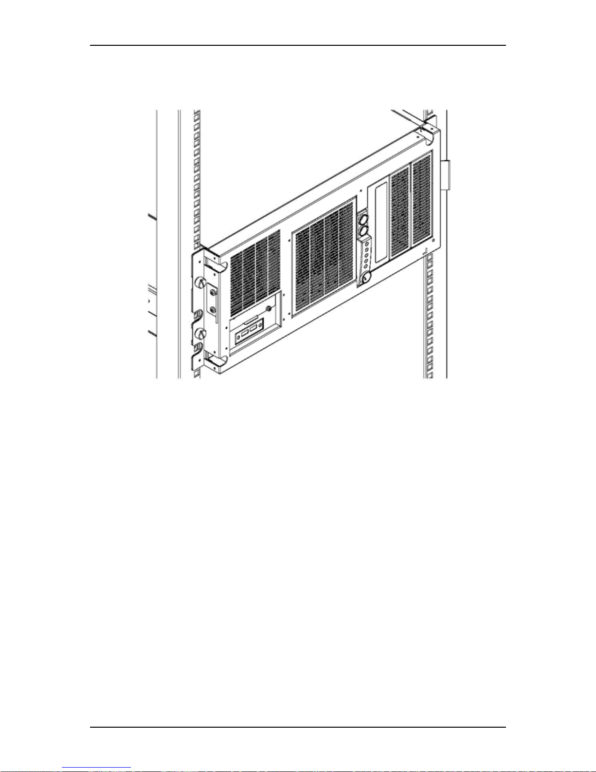
User Guide
62
www.bull.com
3. Repeat steps 1 to 2 for the left support rail.
4. Take the server and fix it into the bay.
Figure 23: fixing the server in the bay
5. Fix the filler with M5 screws, above the server.
Page 63

User Guide
63
www.bull.com
Making Connections
Connect your keyboard, monitor, and mouse. Also connect any external peripheral
devices such as a printer or scanner by following the instructions included with these
devices.
Caution: Damage to the system may result if the keyboard/ mouse cable
(other than USB) is inserted or removed when power is applied to the system.
Inserting a telephone line connector into a LAN RJ-45 port may result in
personal injury and equipment damage.
Page 64

User Guide
64
www.bull.com
T840 E2 Power Supply
Depending on your configuration, your system features one of the power supplies
described below:
■ A hot-swappable power supply fitted with one or two power supply modules
(implying redundancy features).
■ A fixed power supply.
Connecting the Power Cord(s)
Plug the female end of the AC power cord(s) shipped with your system into the input
receptacle(s) on the rear of your system power supply.
Plug the male end of the power cord(s) into NEMA 5-15R outlet(s) for 100-120 VAC
or NEMA 6-15R outlet(s) for 200-240 VAC.
If a power cord supplied with the system is not compatible with the AC wall outlet in
your region, obtain a suitable power cord that meets the following criteria:
■ The power cord must be rated for the available AC voltage and have a current
rating that is at least 125% of the current rating of the system.
■ The power cord connector that plugs into the wall outlet must be terminated in a
grounding-type male plug designed for use in your region. It must have
certification marks showing certification by an agency acceptable in your region.
■ The power cord connector that plugs into the system must be an IEC- type CEE-22
female connector.
■ The power cord must be less than 1.8 meters (6.0 feet) long.
When connecting the power cord(s) to a power control unit such as a UPS unit, confirm
that the power control unit is powered OFF. Connecting the power cord(s) while power
is supplied to the power control unit may cause a failure.
Warning: Do not attempt to modify or use the supplied AC power cord if it
is not the exact type required.
Page 65
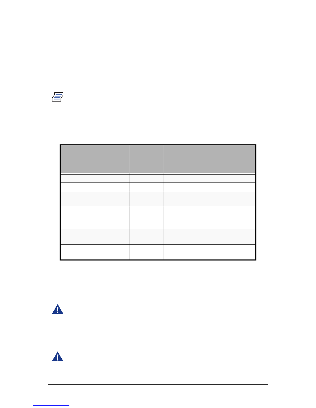
User Guide
65
www.bull.com
Hot-Swappable Power Supply Features
This hot-swappable power supply consists of two independent modules.
It can function properly with only one module.
However, if two modules are fitted, if one of the power modules should fail, the other
one will supply power to the system until you can change the failed module. The failed
module can be hot-swapped.
Note: Connect both power modules to power outlets to ensure continuous
operation.
Power Supply LEDs
There are two LEDs on the back of the power supply. Refer to the table below for more
information.
The PSU is protected against over-temperature conditions that may be caused by a
reduction of the fan cooling or an excessive ambient temperature. In OTP mode, the
power supply unit will eventually shut down.
Hot-Swapping a Power Module
Warning: Hazardous voltage, current, and energy levels are present inside
the power supply. There are no user-serviceable parts inside it; servicing of
the power supply should be done only by technically qualified personnel.
1. Observe the safety and ESD precautions listed in “General Safety
Information” on page 96.
2. Remove the power cable from the defective power supply.
Warning: Put on protective gloves before you follow the instructions
below. The power modules are very hot and there is a risk of severe burns.
Table 2: Power Supply LEDs
Power Supply Condition Status LED
(AC OK /
Power Supply Fail)
Power LED
(Power
Good)
Remarks
AC Power Off OFF OFF
AC Power On in Standby Green OFF
AC ON and all outputs in
Normal
Green Green
Any DC outputs in short
circuit
Green OFF Power distribution
module board only.
Module OK.
DC Fan not spinning Amber OFF Module protection
only
Over-Temperature Protection (OTP)
Amber Green Send out alert signal
Page 66
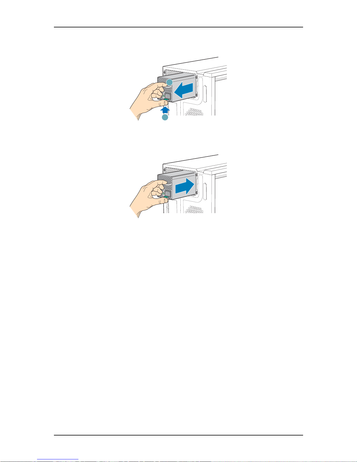
User Guide
66
www.bull.com
3. Press up on the green latch (A) while pulling on the handle (B) to remove the
hot-swap power supply from the chassis.
Figure 24: Removing the Hot Swap Power Supply Module from the Chassis
4. Insert the new hot swap power supply module.
Figure 25: Inserting Hot Swap Power Supply Module in Chassis
5. Connect the power cable to the replaced hot swap power supply.
TP00856
A
B
TP00854
Page 67

User Guide
67
www.bull.com
Using the System
The following sections describe how to use this system properly and safely, including
an explanation of the system power on/off sequences, what the POST program checks
in the system, and how to perform a forced power shutdown.
When using the system the following precautions should be observed:
■ Make sure you power off the system before connecting or disconnecting cables
between the system and peripheral devices. Connecting or disconnecting the cables
while the system is powered on may cause malfunction or failures within the
system. Note that this warning does not apply to hot-plug devices.
■ Check that the removable media drive access lamp is unlit before turning off the
system or ejecting the media. Doing so avoids damaging the data stored on the
media.
■ When you turn off the system, wait at least 10 seconds before turning it on again.
Cycling the power immediately may cause malfunctions or failures in the system.
■ Power off the system and unplug the power cord before relocating the system.
Moving the system while it is powered on may cause malfunctions or failures in
the system.
■ Clean the system regularly. Regular cleaning prevents failures of the system and of
its components.
■ Lightning may cause a momentary voltage drop. To prevent this problem, we
recommend you install an uninterruptible power supply unit.
■ Only use options qualified for the system. An option we did not qualify may be
installed in or connected to the system, but it may fail to operate normally or even
cause failures that will not covered by the warranty.
Page 68
User Guide
68
www.bull.com
Powering On your System
Caution: Never turn off the system before the characters following the Boot-
BIOS logo are displayed on the screen.
Power on your system as follows.
1. Connect the power cord of your system. You may need to wait 30 seconds
before pressing the power button as mentionned in step 5.
2. Make sure all external devices, such as a video display, keyboard, and mouse
(optional) have been connected, and that their power cords are connected.
3. Power on the video display and any other external devices.
Note: If the system power cor d(s) is connected to a power control unit such as
a UPS (Uninterruptible Power Supply) make sure that the power control unit
is powered on.
4. If applicable, open the door behind which the power button is located.
5. Press the POWER button to power on the system. The POWER lamp lights
green. If it is does not light, make sure that the ac power cord is connected to a
functional ac power source.
After a few seconds your system begins the internal Power-On Self Tests (POST). The
POST automatically checks the system board, CPU(s), memory, keyboard, mouse, and
most installed peripheral devices. It also displays the start message of the BIOS setup
utility.
The POST check results should be especially monitored in the following cases:
■ When the system is being used for the first time.
■ When the system appears to fail.
■ When the system beeps many times between power-on and the OS start-up.
■ When an error message appears on the screen.
Note: For error messages that appear on the display unit, refer to “Error
Messages” on page 163.
Always allow the POST to complete before powering down your system.
If you have problems powering on your system, refer to “Solving Problems” on
page 148.
If an operating system was factory-installed on your system, you can start using it.
If not, insert the ExpressBuilder disc into the optical disc drive, reboot the system and
follow the screen prompts to run ExpressBuilder.
Page 69

User Guide
69
www.bull.com
Powering Off your System
To turn the system power off:
1. Shutdown the operating system (OS). In most cases, this will shut down the
system after a few seconds (the POWER lam turns off). This is called a
software power-off.
If necessary, press the POWER switch on the front of the computer chassis
again to power off the system. The POWER lamp turns off.
2. Power off the peripheral devices.
Note: If the system power cord is connected to a power control unit such as
an UPS (Uninterruptible Power Supply), refer to the UPS user's guide for
proper power-off procedures.
Page 70

User Guide
70
www.bull.com
Forcing a Power Shutdown
A forced power shutdown can be used when performing a soft power-off or pressing
the power on/off switch does not power off the system.
To perform a forced power shutdown, press on the power on/off switch located on the
front panel of the system for at least 4 seconds to force the system power off.
T o power on after a forced shutdown, wait at least 10 seconds and then power on again.
Page 71

User Guide
71
www.bull.com
Resetting the System
There are two ways to reset the system.
Caution: Resetting the system clears the DIMM memory and the data in
process. To reset the system when it is not frozen, make sure that no
processing is in progress.
■ Soft reset
If the system halts before starting the OS, press and hold Ctrl and Alt and press
Delete. This restarts the system.
■ Hard reset (depending on your configuration)
Press the reset button at the front of the system. Refer to “Powering On your System”
on page 68.
Page 72

User Guide
72
www.bull.com
Configuring Your System
Configuration and setup utilities are used to change your system configuration.
■ RAID Configuration Utilities
Depending on your configuration (SATA, SAS, combination of these) and on your
disk drive controller, one or several RAID Configuration Software Utilities may be
available on your system. These software utilities may allow you to perform some
of the following actions: configure the RAID level, setup arrays, format the drives,
etc.
■ BIOS Setup Utility
You can configure your system, as well as option boards you may add to your
system, using the BIOS Setup Utility. Several unique system parameters are
configured using the BIOS Setup, which is stored in the system FLASH memory.
If your system has been factory configured, the BIOS Setup Utility does not need
to be run unless you want to change the password or security features, add certain
types of option boards or devices, or upgrade your system board.
For more information about the BIOS Setup Utility, see “BIOS Setup Utility” on
page 171.
Page 73

User Guide
73
www.bull.com
Configuring RAID
RAID Configuration Utility
The RAID (Redundant Array of Inexpensive Devices) option available for your system
is either a RAID controller board, a RAID chipset on the motherboard, or both
(depending on your configuration) which gives your system the added security of fault
tolerance.
■ If you want to change the RAID level or add additional hard disk drives to the
array, use the RAID configuration utility. The RAID configuration utility is
included with the RAID controller.
■ If you are adding the RAID controller to an existing system, the RAID
configuration utility allows you to configure your disk array before reinstalling
your network operating system. The RAID controllers support various versions of
RAID technology (referred to as RAID levels). To use any RAID level, you must
configure the RAID controller using the RAID configuration utility prior to
installing your Network Operating System.
For an explanation of this utility, check this user’s guide for basic informations,
and refer to the documentation that comes with the RAID controller (the
manufacturer’s documentation is generally included on the ExpressBuilder disc). It
describes RAID technology and provides tips on making your array perform well
in your specific application. It also covers array hardware preparation,
configuration, and initialization. After completing the steps in the manual, you can
install your Operating System.
Page 74
User Guide
74
www.bull.com
RAID Levels
RAID 0 and RAID 1
■ RAID0 (striping)
When a logical drive is striped, the read and write blocks of data are interleaved
between the sectors of multiple disk drives. Performance is increased, since the
workload is balanced between drives or “members” that form the logical drive.
Identical drives are recommended for performance as well as data storage
efficiency. The logical drive's data capacity is equal to the number of drive
members multiplied by the smallest logical drive member's capacity.
RAID 0 Stripe interleaves data across multiple drives For example, one 100GB
and three 120GB drives will form a 400GB (4 x 100GB) logical drive instead of
460 GB.
Warning:
•
RAID0 does not have data redundancy. When a hard disk drive failure
occurs, data cannot be restored.
• Logical capacity of the array becomes a multiple of the connected
hard disk drive.
■ RAID1 (mirroring)
When a logical drive is mirrored, identical data is written to a pair of disk drives,
while reads are performed in parallel. The reads are performed using elevator seek
and load balancing techniques where the workload is distributed in the most
efficient manner. Whichever drive is not busy and is positioned closer to the data
will be accessed first.
With RAID 1, if one disk drive fails or has errors, the other mirrored disk drive
continues to function. This is called Fault Tolerance. Moreover, if a spare disk
drive is present, the spare drive will be used as the replacement drive and data will
begin to be mirrored to it from the remaining good drive.
Due to the data redundancy of mirroring, the capacity of the logical drive is only
the size of the smallest disk drive. For example, two 100GB disk drives which
have a combined capacity of 200GB instead would have 100GB of usable storage
when set up in a mirrored logical drive. Similar to RAID 0 striping, if disk drives
of different capacities are used, there will also be unused capacity on the larger
drive.
RAID Configuration Number of required hard disk drives
RAID 0 2
RAID 1 2
RAID 10 4
RAID 5 3
Page 75

User Guide
75
www.bull.com
Warning:
•
RAID1 reads or writes data to/from the several hard disk drives at the
same time. The disk access performance is lower than the single disk.
• Logical capacity of the array is equal to one hard disk drive connected.
Raid 10 & RAID 5
These RAID levels may also be available on your system. Browse through the next
sections of this User’s Guide for more information.
■ RAID 10
Mirror/Stripe combines both of the RAID 0 and RAID 1 logical drive types. It can
increase performance by reading and writing data in parallel while protecting data
with duplication. At least four disk drives are needed for RAID 10 to be installed.
With a four-disk-drive logical drive, one drive pair is mirrored together then
striped over a second drive pair.
The data capacity is similar to a RAID 1 logical drive, with half of the total storage
capacity dedicated for redundancy. An added plus for using RAID 10 is that, in
many situations, such a logical drive offers double fault tolerance. Double fault
tolerance may allow your logical drive to continue to operate depending on which
two disk drives fail.
■ RAID 5
RAID level 5 organizes data across the disk drives of the logical drive, and
distributes parity information across the disk drives along with the data blocks.
This organization allows increased performance by accessing multiple disk drives
simultaneously for each operation, as well as fault tolerance by providing parity
data. In the event of a disk drive failure, data can be re-calculated by the RAID
system based on the remaining data and the parity information.
The adjustable block size of the RAID 5 logical drive allows for performance
tuning based on the typical I/O request sizes for your system. The block size must
be set at the time the logical drive is created and cannot be adjusted dynamically.
RAID 5 makes efficient use of hard drives and is the most versatile RAID Level. It
works well for file, database, application and web servers.
The capacity of a RAID 5 logical drive is the smallest disk drive size multiplied by
the number of disk drives, less one. Hence, a RAID 5 logical drive with four 100
GB disk drives will have a capacity of 300 GB. A logical drive with two 120 GB
disk drives and one 100 GB disk drive will have a capacity of 200 GB.
Page 76

User Guide
76
www.bull.com
RAID Configuration using the Intel® Embedded
Server RAID BIOS Configuration Utility
Description
The Intel® Embedded Server RAID BIOS Configuration utility allows a user to:
■ Create, add, modify, and clear logical drive configurations.
■ Initialize or rebuild the configured drives.
■ Set the boot drive.
■ Create a global hotspare drive.
■ View physical and logical drive parameters.
■ View and set adapter properties, including consistency check and auto-resume.
SATA and SAS systems use different versions of the Intel Embedded Server RAID
BIOS Configuration utility, but both versions use the same keystrokes and contain
identical menus. The utility menus show limited help at the bottom of the screen and
selections are chosen with the arrow keys and the space bar. A warning is displayed if
there is no logical drive available to be configured.
Enabling RAID in the BIOS
RAID should first be enabled in the BIOS before you can configure it. For more
information, refer to “BIOS Setup Utility” on page 171.
Entering the Intel Embedded Server RAID BIOS Configuration Utility
When the SATA RAID or SAS RAID options are enabled in the server BIOS, an option
to enter the Intel Embedded Server RAID BIOS Configuration utility displays during
the server boot process. To enter the utility, press the <Ctrl> + <E> when prompted.
Note: The onboard SAS and SATA RAID features are optional. Depending on
your configuration, they may or may not be available on your system.
Setting Up the RAID Feature
Please refer to the Intel® Embedded Server RAID BIOS Configuration Utility Software
Guide included on the ExpressBuilder disc for more information.
Page 77
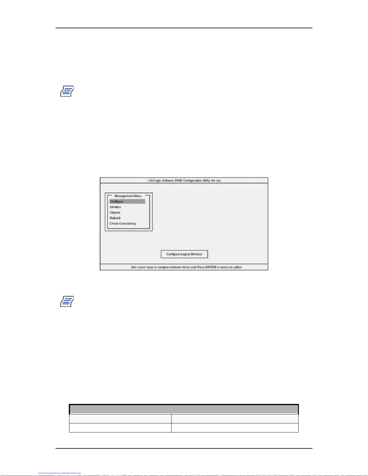
User Guide
77
www.bull.com
RAID Configuration using the LSI Logic
Software RAID Configuration Utility
Use this utility to set up the RAID configuration of your hard disk drives.
Note: This utility cannot be run via the remote console feature of
DianaScope.
Running the Setup Utility
1. Press Esc when the full screen logo appears after you have powered on the
server.
The POST screen appears.
2. Check the description shown on the POST screen, and then press Ctrl + M.
The LSI Logic Software RAID Setup Utility starts.
Figure 26: LSI Logic Software RAID Configuration Utility
TOP Menu (Management Menu)
Note: To exit the utility, press Esc in the TOP menu of LSI Logic Software
RAID Setup Utility. Select Yes, and then press Ctrl + Alt + Delete to reboot
the server when prompted to do so.
Tree Menu
+: Selection/execution parameter
←: Setting parameter.
•: Information display
>: Can be set (modified) after creation of logical drive
Table 3: Tree Menu
Menu Description
+Configure Performs Configuration settings
+Easy Configuration Set configuration (Using fixed value)
Page 78
User Guide
78
www.bull.com
+New Configuration Set new configuration
+View/Add Configuration Additional setting / viewing configuration
+Clear Configuration Clear configuration
+Select Boot Drive Chose Bootable Logical Drive
+Initialize Initialize logical drive
+Objects Various settings
+Adapter Set disk array controller
+Sel. Adapter Clear configuration
←Rebuild Rate
30
←Chk Const Rate
30
←FGI Rate
30
←BGI Rate
30
←Disk WC
Off
←Read Ahead
On
←Bios State
Enable
←Stop on Error
No
←Fast Init
Enable
←Auto Rebuild
On
←Auto Resume
Enable
←Disk Coercion
1GB
←Factoty Default
+Logical Drive Logical drive operation
+Logical Drives Select logical drive (when multiple logical drives exist)
+Initialize Initialize logical drive
+Check Consistency Check logical drive redundancy
+View/Update Parameters Display logical drive information
• RAID
Display RAID level
• SIZE
Display logical drive capacity
• Stripe SIZE
Display stripe size
• #Stripes
Display the number of hard disk drives in logical drive
• Sta te
Display logical drive status
• Spans
• Disk WC
Off: Write through
On: Write back
• Read Ahead
+Physical Drive Physical drive operation
+Physical Drive Selection Menu Select physical drive
+Make HotSpare Set as hot-spare disk for auto rebuilding
Table 3: Tree Menu (Continued)
Menu Description
Page 79
User Guide
79
www.bull.com
Operating Procedures for the Setup Utility
Creating/Adding a Configuration
1. Run the LSI Logic Software RAID Setup Utility.
Select Configure → New Configuration from the TOP menu (Management
Menu).
+Force Online Make a disk online
+Force Offline Make a disk offline
+Drive Properties Display hard disk drive information
• Device Type
Hard disk drive type
• Capacity
Hard disk drive capacity
• Product ID
Hard disk drive model
• Revision No.
Hard disk drive revision
+Rebuild Perform rebuilding
+Check Consistency Perform logical drive redundancy check
Run the LSI Logic Software RAID Setup Utility
Set new configuration information (pack/logical drive settings)
Check the logical drive settings
Initialize logical drive
Perform a Consistency Check
Exit the LSI Logic Software RAID Setup Utility
Table 3: Tree Menu (Continued)
Menu Description
Page 80

User Guide
80
www.bull.com
Select View/add Configuration to add a configuration.
Caution:
•
Creating a configuration using the New Configuration menu clears any
existing configuration information. To add configuration information to
an existing configuration, select View/add Configuration.
• You cannot create a Spanning of RAID1 or set the logical drive capacity
on the Easy Configuration menu.
Use the New Configuration or View/Add Configuration instead.
Page 81
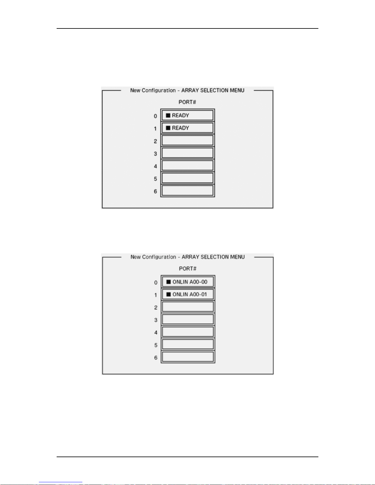
User Guide
81
www.bull.com
2. When prompted to proceed, select Yes.
The Scan Device starts (the scanning information is displayed at the bottom of
the screen). Once the Scan Device is completed, the New Configuration - Array
Selection Menu screen appears.
Figure 27: New Configuration - Array Selection Menu screen
3. Move the cursor onto the hard disk drive to be packed by using the cursor key
and then press Space to select it.
The display for the selected hard disk drive changes from Ready to Online.
Figure 28: New Configuration - Array Selection Menu screen
4. Press F10 to set Select Configurable Array(s).
Page 82
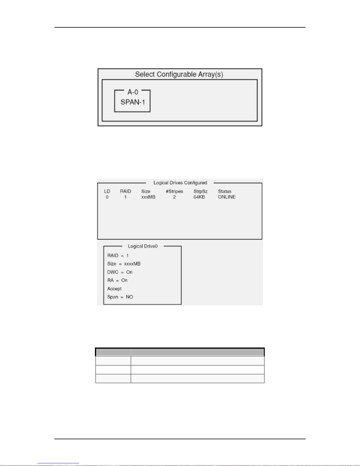
User Guide
82
www.bull.com
5. Press Space.
SPAN-1 is set.
Figure 29: Select Configurable Arrays screen
6. Press F10 to create a logical drive.
The Logical Drives Configure screen appears. (The figure below shows an
example of a RAID1 configured with two hard disk drives.)
Figure 30: Logical Drives Configure screen
7. Select RAID, Size, DWC, RA, or Span by using cursor keys. Then press Enter
to fix the selection and set each value.
(1) RAID: Sets the RAID level.
The selectable RAID level varies depending on the number of hard disk drives
that configure a pack.
(2) Size: Sets the logical drive size.
Up to 40 logical drives can be created per disk array controller.
Parameter Remarks
0 RAID0
1RAID1
10 Spanning of RAID1
Page 83
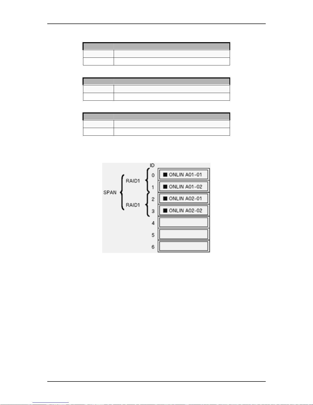
User Guide
83
www.bull.com
(3) DWC: Sets the parameter for the Disk Write Cache.
(4) RA: Sets the parameter for the Read Ahead.
(5) Span: Sets the Span.
When performing a Span, create two or more sets of the same pack at the pack
creation, as shown in the figure below.
Figure 31: Spanning of RAID1
8. When all the settings are completed, select Accept and then press Enter to
create the logical drive.
The created logical drive is displayed in the Logical Drive Configured screen.
9. After creating a logical drive, press Esc to close the screen.
Go back to the Save Configuration? screen and then select Yes to save the
configuration.
Parameter Remarks
Off Write through
On Write back
Parameter Remarks
Off Does not perform read ahead
On Performs read ahead
Parameter Remarks
SPAN=NO Does not set span
SPAN=YES Sets span
Page 84
User Guide
84
www.bull.com
10. Once it is confirmed that the configuration has been saved, press Esc to return
to the Top menu screen.
11. On the Top menu screen, select Objects → Logical Drive → View/Update
Parameters to check the logical drive information.
12. Select Initialize in the Top menu screen.
13. When the Logical Drives screen appears, move the cursor to the logical drive
to be initialized, and press Space.
The logical drive is selected.
14. Press F10 to start the initialization, and press Yes when prompted to do so.
When the progress bar in the Initialize Logical Drive Progress screen reaches
100%, initialization is completed.
15. Execute a Check Consistency on the logical drive that has been initialized.
Refer to “Check Consistency” on page 87 for more information.
16. Press Esc to return to the Top menu and exit the LSI Logic Software RAID
Setup Utility.
Caution:
•
Be sure to execute a Check Consistency after creating a configuration.
• Check Consistency has two modes: "check and recover" and "check
only".
Manual Rebuild
1. Replace a hard disk drive and power on the server.
2. Run the LSI Logic Software RAID Setup Utility.
Replace a hard disk drive
Run the LSI Logic Software RAID Setup Utility
Execute the rebuilding
Exit the LSI Logic Software RAID Setup Utility
Page 85
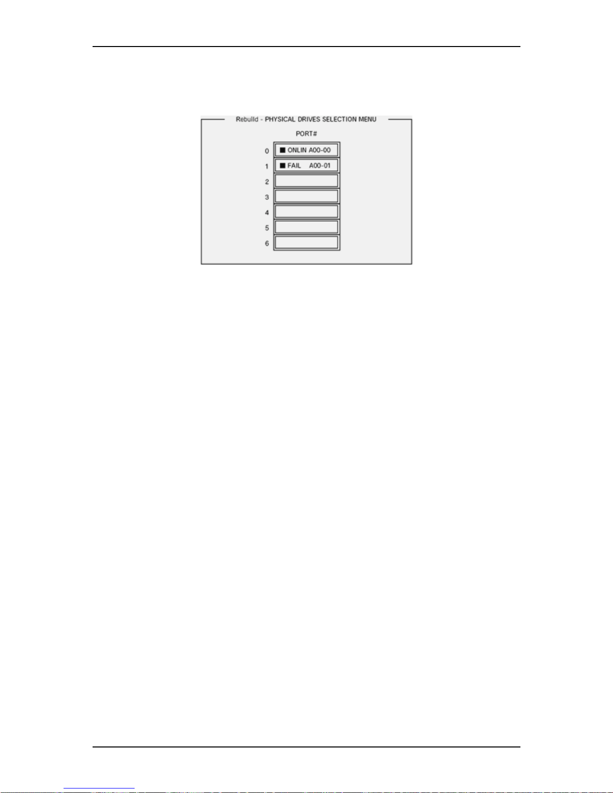
User Guide
85
www.bull.com
3. Select Rebuild from the Top menu.
The Rebuild – Physical Drives Selection Menu screen appears.
Figure 32: Rebuild – Physical Drives Selection Menu
4. Move the cursor onto the hard disk drive displaying "FAIL" and then press
Space to select it.
Several hard disk drives can be selected (simultaneous rebuilding.)
5. The Fail indication for the selected hard disk drive starts blinking.
6. Once the hard disk drive is selected, press F10 to start rebuilding.
7. Press Yes when prompted to do so. The rebuild process starts.
When the progress bar in the Rebuild Physical Drives in Progress screen
reaches 100%, the rebuilding is completed.
8. Press Esc to return to the Top menu and exit the LSI Logic Software RAID
Setup Utility.
Page 86
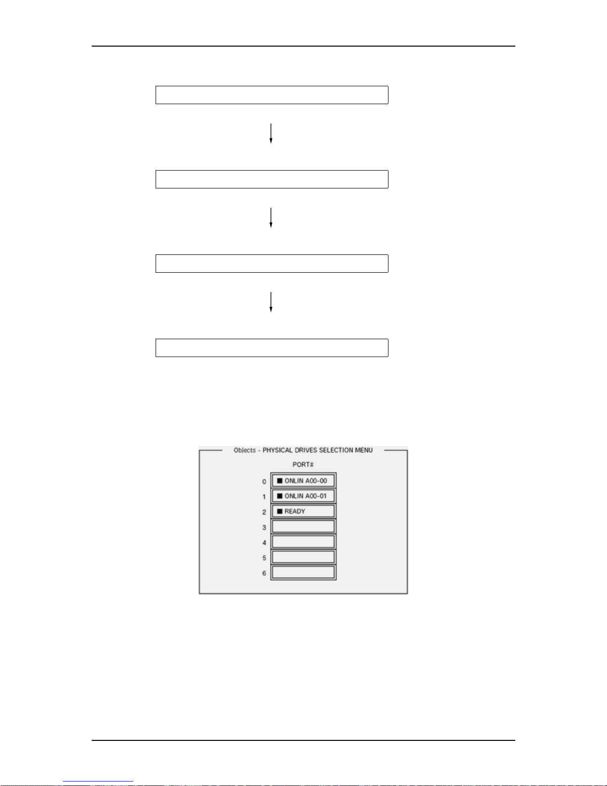
User Guide
86
www.bull.com
Setting a Hot Spare
1. Install a hard disk drive to be used as hot spare, and then power on the server.
2. Run the LSI Logic Software RAID Setup Utility.
3. Select Objects → Physical Drive from the TOP menu.
The Objects - Physical Drive Selection Menu screen appears.
Figure 33: Objects - Physical Drive Selection Menu screen
4. Move the cursor onto the hard disk drive to be used as hot spare and press
Enter.
5. The "Port #X" screen appears. Select Make HotSpare.
6. Select Yes when prompted to do so.
The hard disk drive indication changes to "HOTSP."
Install a hard disk drive
Run the LSI Logic Software RAID Setup Utility
Set for hot spare.
Exit the LSI Logic Software RAID Setup Utility
Page 87
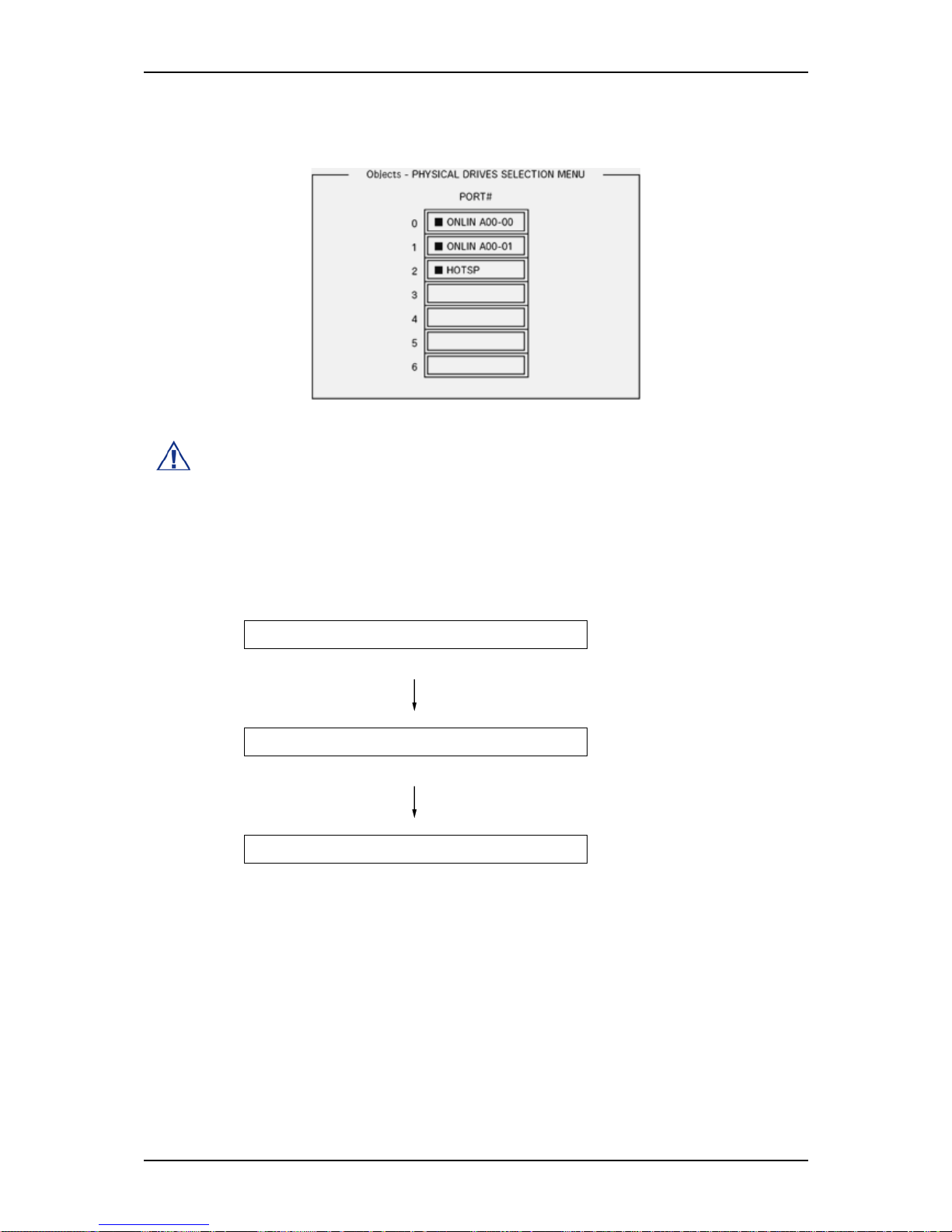
User Guide
87
www.bull.com
7. Press Esc to return to the Top menu and exit the LSI Logic Software RAID
Setup Utility.
Figure 34: Objects - Physical Drive Selection Menu screen
Caution:
•
Select "Objects" → "Physical Drive" → "Port #X" → "Force Offline" to
cancel the hot spare setting.
• When two or more hard disk drives (of the same capacity) are assigned
as hot spare, rebuilding starts with the one with the smaller CH number/
ID number.
Check Consistency
1. Run the LSI Logic Software RAID Setup Utility.
2. Select Check Consistency from the Top menu.
The Logical Drives screen appears.
3. Move the cursor onto the logical drive to be checked, and press Space to select
it.
4. Once the logical drive is selected, press F10 to start the consistency check.
5. When prompted to do so, press "Yes".
The consistency check starts.
When the progress bar in the Check Consistency Progress screen reaches
100%, the consistency check is completed.
Run LSI Logic Software RAID Setup Utility
Perform Check Consistency
Exit LSI Logic Software RAID Setup Utility
Page 88

User Guide
88
www.bull.com
6. Press Esc to return to the Top menu and exit the LSI Logic Software RAID
Setup Utility.
Caution:
•
Be sure to execute a Check Consistency after creating a configuration.
• Check Consistency has two modes: "check and recover" and "check
only".
Others Operations
Clear Configuration
Clears the configuration information. Select Configure → Clear Configuration from
the Top menu. Executing Clear Configuration clears all the configuration information
on the disk array controller and hard disk drives. The configuration information on all
the channels of the disk array controller is also cleared.
Note:
•
When the configuration information on the disk array controller and
that on the hard disk drive do not match (excluding at the replacement of
a faulty disk array controller), configuration may fail if you select the
configuration information on the disk array controller. In this case,
execute "Clear Configuration" to create the configuration again.
• Use the MegaRAID Storage Manager to delete a specific logical drive.
Force Online
Puts online a hard disk drive being in the FAIL status.
Select Objects → Physical Drive → (select hard disk drive) → Force Online from the
Top menu.
Rebuild Rate
Sets the Rebuild Rate.
Select Objects → Adapter → Sel. Adapter → Rebuild Rate from the TOP menu.
The value range is 0% to 100%. The Default value (recommended) is 30%.
Hard disk drive information
Checks the hard disk drive information.
Select Objects → Physical Drive → (sel ect hard disk drive) → Drive Properties from
the Top menu.
Page 89

User Guide
89
www.bull.com
RAID Configuration using the Universal RAID
Utility
Use this utility to set up the RAID configuration of your hard disk drives.
Note: For more information, refer to the specific documentation included on
the ExpressBuilder DVD-ROM.
Page 90

User Guide
90
www.bull.com
Configuring the BMC
Overview
The servers’ Integrated Baseboard Management Controller (iBMC) provides the ability
for IPMI-based management systems to monitor and retrieve information from the
server ‘Out-Of-Band’, independent of whether any operating system is running.
To permit management systems to do this it is necessary to configure the BMC with an
IP address and user credentials. This is done using the SYSCFG (System
Configuration) utility.
An additional Windows application, SELVIEW (System Event Log Viewer) is provided
to view the contents of the BMC’s System Event Log.
Installation
Linux
Refer to the release notes in the \BMC\Linux\<version>\SysCfg directory for
instructions on installing the Linux version of the SYSCFG utility.
Windows
Windows-based SYSCFG and SELVIEW utilities are provided on the ExpressBuilder
DVD. These can be found in the \BMC\Windows\<arch> directory.
These utilities can be run directly from the ExpressBuilder DVD.
IMB Driver Installation
To use the Windows BMC utilities it is necessary to first install the Intelligent
Management Bus device driver. This driver provides the Operating System with access
to the BMC.
To install the IMB device driver from the DVD drive, run the following from the
Command Prompt:
<cd-drive>:
cd \BMC\Windows\<arch>\IMBDRIVER
install.cmd
Once installed, the device can be seen in the Device Manager under the System Devices
section.
SELVIEW
SELVIEW (System Event Log Viewer) is provided to view the contents of the BMC’s
System Event Log and save the log to a file. This file can then be sent to a support team
for analysis.
This utility is only available for the Windows Operating System.
Page 91
User Guide
91
www.bull.com
Refer to the release notes for further information on using SELVIEW.
SYSCFG
The SYSCFG command-line utility is used to configure the IP address and user
credentials of the BMC. Although Windows and Linux versions of this utility are
provided, their command syntax is the same.
Refer to the System Configuration Utility User Guide found on the ExpressBuilder
DVD for further details of each command.
Execute the following commands (in bold) to change the required parameters.
Note:
•
These commands must be run from the directory containing the
SYSCFG.EXE program.
• Entering some commands may produce an error, caused by the BMC
being too busy at that time to respond. Re-enter the command a few
seconds later.
Reset BMC
Restore the factory default BMC settings:
Command:syscfg /rfs
Reset the BMC:
Command:syscfg /rbmc
Note: Wait 10 seconds before entering further configuration commands.
IP address Configuration
Note: The IP address of the BMC operates independently of any operating
system IP address and must be unique to avoid conflicts.
Page 92
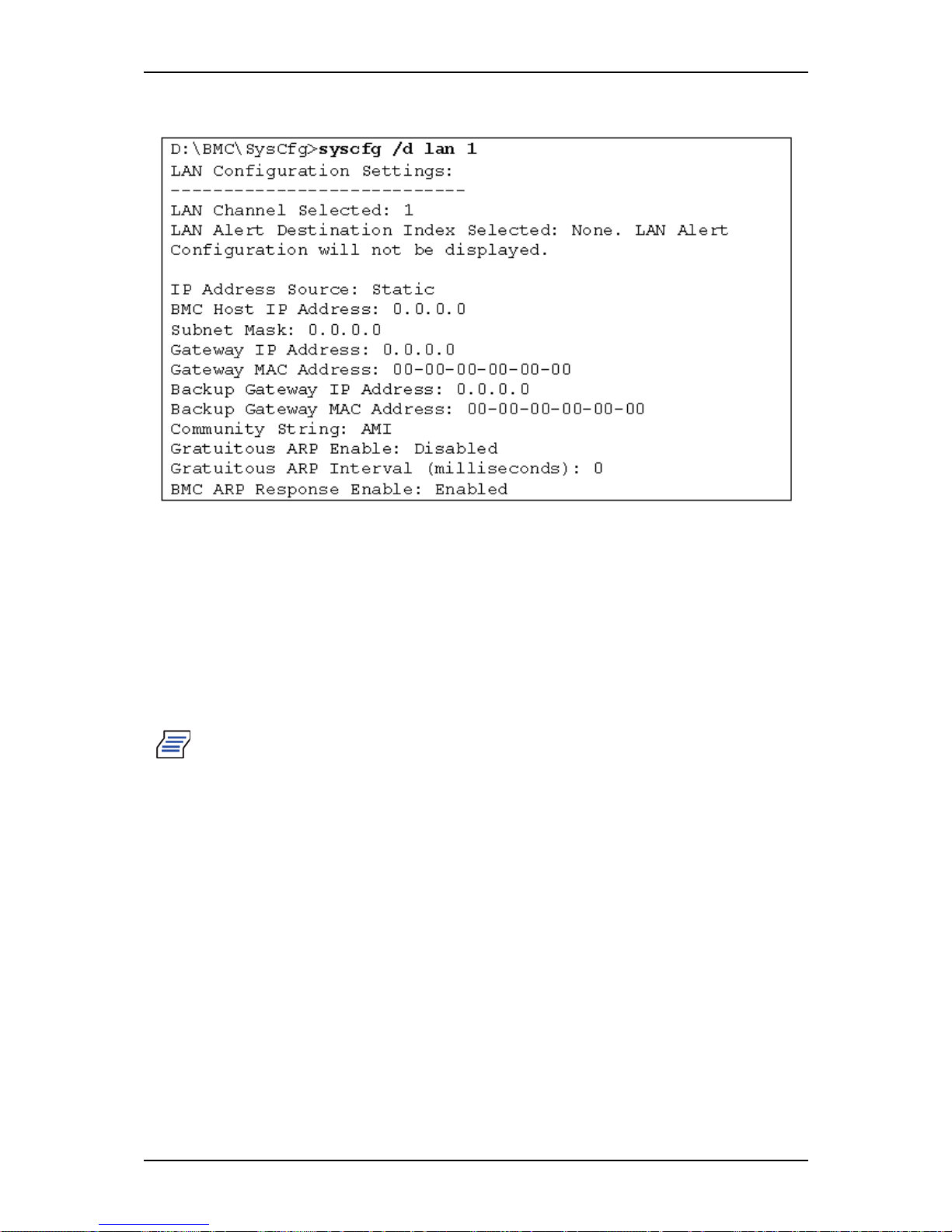
User Guide
92
www.bull.com
To display the default LAN configuration details, use the following command:
IP address
syscfg /le 1 static <IP-address> <subnet mask>
Exemple : syscfg /le 1 static 192.168.1.10 255.255.255.0
Default Gateway
Syntax:syscfg /lc 1 12 <gateway-IP-address>
Example: syscfg /lc 1 12 192.168.1.254
Note: The BMC may not work correctly if it does not have a default gateway
configured. Please ensure that it is configured.
Page 93

User Guide
93
www.bull.com
To confirm the LAN configuration details, use the following command:
C:\BMC\SysCfg>syscfg /d lan 1
LAN Configuration Settings:
---------------------------
LAN Channel Selected: 1
LAN Alert Destination Index Selected: None. LAN
Alert Configuration will not be displayed.
IP Address Source: Static
BMC Host IP Address: 192.168.1.10
Subnet Mask: 255.255.255.0
Gateway IP Address: 192.168.1.254
Gateway MAC Address: 00-00-00-00-00-00
Backup Gateway IP Address: 0.0.0.0
Backup Gateway MAC Address: 00-00-00-00-00-00
Community String: AMI
Gratuitous ARP Enable: Disabled
Gratuitous ARP Interval (milliseconds): 0
BMC ARP Response Enable: Enabled
Page 94
User Guide
94
www.bull.com
User Details
Five users can be defined within the BMC. By default, these users are configured as
follows:
To view the configuration of a particular user, use the following command:
Syntax:syscfg /d user <user#> 1
Examples:
It is not possible to delete a user – only change its’ name and password. Additionally, it
is not possible to change the name of the user #2, the root account.
User # User Name Status
1
Anonymous User
Disabled
2
root
Enabled
3
test1
Disabled
4
test2
Disabled
5
test3
Disabled
C:\BMC\SysCfg>syscfg /d user 2 1
User Configuration Settings:
-----------------------------
User ID Selected: 2
Channel Selected: 1
User Name: root
User Status: Enabled
Privilege Level Limit: Admin
SOL Enable: Enabled
C:\BMC\SysCfg>syscfg /d user 5 1
User Configuration Settings:
-----------------------------
User ID Selected: 5
Channel Selected: 1
User Name: test3
User Status: Disabled
Privilege Level Limit: Admin
SOL Enable: Enabled
Page 95
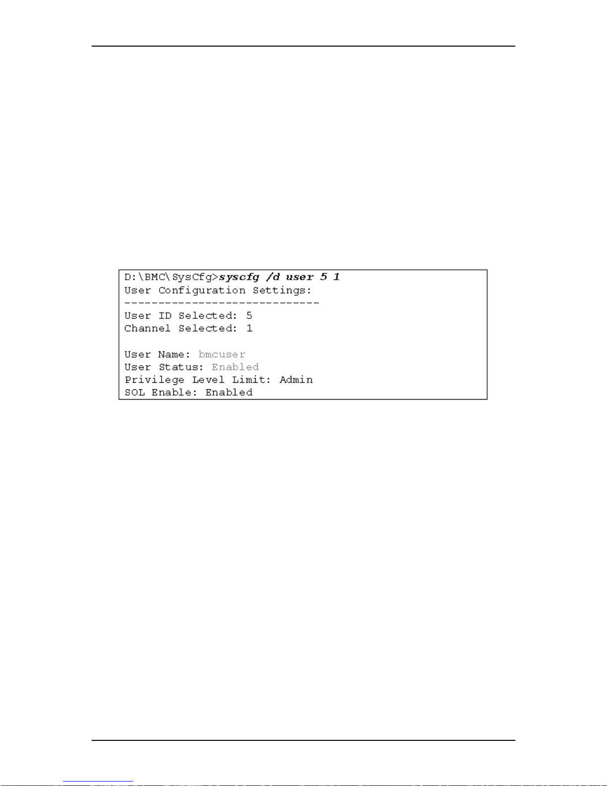
User Guide
95
www.bull.com
In this example, we will change the name and password of user#5 and enable it.
User Name and password
To change the name and password of a user, run the following command:
Syntax:syscfg /user <user#> <new-name> <new password>
Example: syscfg /user 5 bmcuser bmcpassword
Enable User
Ensure that the user is enabled:
Syntax:syscfg /ue <user#> <enable/disable> <channel#>
Example: syscfg /ue 1 enable 1
Now view the new configuration:
With the IP address and User IDs configured and enabled, an IPMI-based management
system can now communicate directly with the BMC.
Page 96

User Guide
96
www.bull.com
Upgrading Your System
General Safety Information
Warning:
•
The DC push-button on/off switch on the front panel does not turn off
completely the system AC power. +5vdc is present on the system board
whenever the AC power cord connects the system to an AC outlet.
Before doing the procedures in this manual, make sure that your
system is powered off and unplug the AC power cord from the back of
the chassis.
• Failure to disconnect the power cord before opening your system can
result in personal injury and equipment damage.
• Operating your system with the covers removed can damage your
system components.
• For proper cooling and airflow, always replace the covers before
powering on your system.
• Avoid burns: If the system has been running, any installed processor
and heat sink on the processor board(s) will be hot.
• To avoid the possibility of a burn, be careful when removing or
installing components that are located near processors.
Contact your sales representative or dealer for a list of the approved optional peripheral
devices.
St atic Precautions
An electrostatic discharge (ESD) can damage disk drives, option boards, and other
components. You can ensure some ESD protection by wearing an anti-static wrist strap
attached to chassis ground when handling system components. Electronic devices can
be easily damaged by static electricity. To prevent damage, keep them in their
protective packaging when they are not installed in your system.
Equipment Log
Use the equipment log form located at the end of this manual to record the model and
serial number of your system, all the installed options, and any other pertinent
information specific to your system. You will need this information when configuring
your system. Refer to “T840 E2 Equipment Log” on page 202.
Page 97

User Guide
97
www.bull.com
T ools Recommended for Upgrading Your
System
Depending on the upgrade, you will need one or more of the following tools:
- Phillips screwdriver (#1 bit and #2 bit)
- Flat-head screwdriver
- Small needle nose pliers
- Pen or pencil
- ESD workstation or anti-static wrist strap (recommended)
Preparing Your System for Upgrade
To prepare your system for installation or removal of system components perform the
following procedure:
1. Observe the safety and ESD precautions listed under “General Safety
Information” on page 96 and “Static Precautions” on page 96 at the
beginning of this chapter.
2. Shutdown the operating system (OS).
3. If necessary, press the power on/off switch on the front panel of the system.
The power-on LED goes out. Refer to “Powering On your System” on
page 68
4. Power off the peripheral devices.
5. Unplug the system power cord(s) from the AC wall outlet(s).
Note: If the system power cord is connected to a power control unit such as
an UPS (Uninterruptible Power Supply), refer to the UPS user's guide for
proper power-off procedures.
6. Unplug all the I/O cables connected to the rear panel of your system.
Page 98
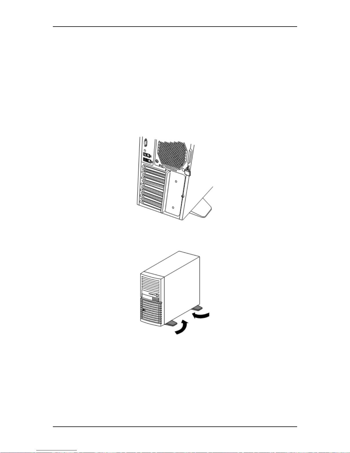
User Guide
98
www.bull.com
Removing the Left Side Door
The right side door provides access to the disk drive bays, to the motherboard and to
the 5.25 inch bay.
1. Make sure the power switches for the computer, video monitor and any
peripheral devices are turned OFF and unplug the power cord (see “General
Safety Information” on page 96).
2. Disconnect the monitor and peripheral devices (printers, for instance) from the
system.
3. Unlock the left side cover if required.
Figure 35: Key lock
4. Fold the four stabilizers at the bottom of the server toward inside.
Figure 36: Fold the stabilizers
Page 99
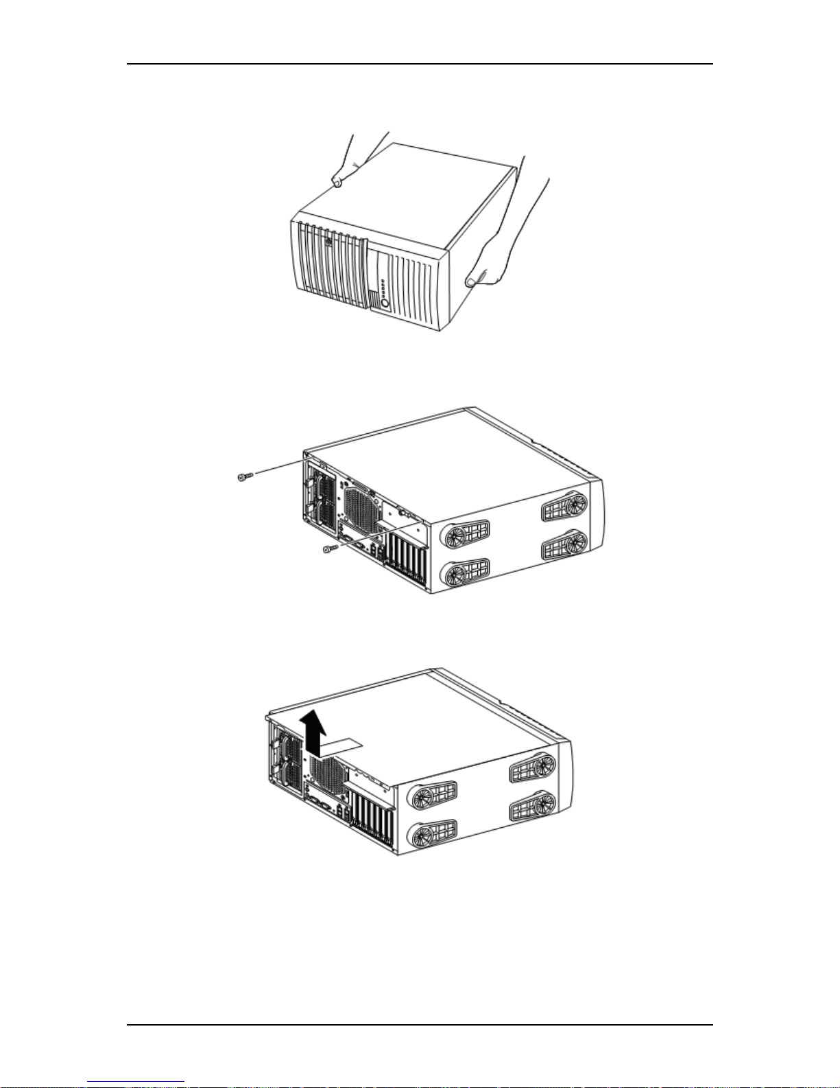
User Guide
99
www.bull.com
5. Lay the server slowly and gently so that its right cover faces the floor.
Figure 37: Lay the server
6. Remove the two screws from the rear of the server.
Figure 38: Remove the two screws
7. Hold the left side cover securely to remove it
Figure 39: Remove the cover
Page 100
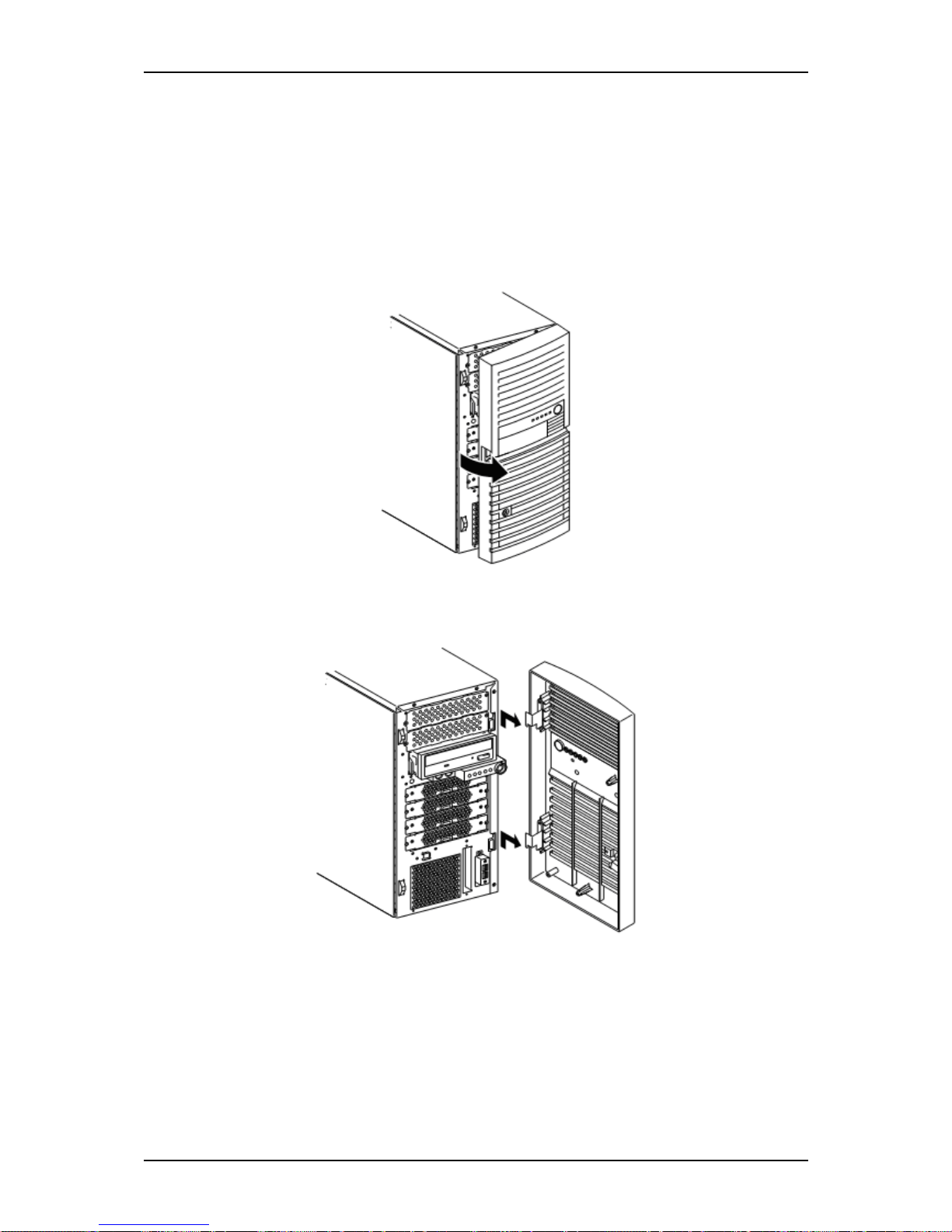
User Guide
100
www.bull.com
Removing the Front Panel
The front mask must be removed to install or remove the hard disk drive and 5.25-inch
device
Follow the procedure below to remove the front mask:
1. Open the front panel
Figure 40: Open the front panel
2. Slide the front mask upward to remove it.
Figure 41: remove the front panel
 Loading...