

Page 1

NovaScale R630 E1
Setup Guide
NOVASCALE
REFERENCE
86 A1 43FA 00
Page 2

Page 3

NOVASCALE
NovaScale R630 E1
Setup Guide
Hardware
June 2008
BULL CEDOC
357 AVENUE PATTON
B.P.20845
49008 ANGERS CEDEX 01
FRANCE
REFERENCE
86 A1 43FA 00
Page 4
Droits de propriété et déni de responsabilité
Les informations contenues dans ce document, y compris les graphiques et les documents connexes, sont la propriété
de NEC Computers et/ou des tiers qui lui ont accordé des licences. NEC Computers et/ou lesdits tiers, selon le cas,
se réservent les brevets, copyrights et autres droits de propriété sur ce document, notamment les droits de conception,
de fabrication, de reproduction, d'utilisation et de commercialisation, sous réserve que d'autres n'en soient pas
bénéficiaires.
La conception et les spécifications des produits décrits dans ce document faisant l'objet d'améliorations constantes,
les informations contenues dans ce document peuvent être modifiées sans préavis. Aucune partie du présent
document ne peut être reproduite sans l'accord préalable écrit de NEC Computers.
Le ou les produits Bull décrits dans ce document sont couverts par l'accord de garantie qui les accompagne.
Cependant, leurs performances dépendent de facteurs tels que leur configuration, les données qu'ils hébergent et
leur utilisation. Leur mise en œuvre pouvant varier en fonction du client, l'adéquation de configurations et
d'applications spécifiques doit être déterminée par ledit client et ne relève pas de la responsabilité de Bull.
Marques commerciales
NEC ESMPRO, NEC DianaScope, NEC MWA, et ExpressBuilder sont des marques ou des marques déposées de
NEC Corporation.
NovaScale est une marque déposée de Bull SAS.
Adobe et Adobe Acrobat sont des marques déposées d'Adobe Systems, Incorporated.
Microsoft, Microsoft Windows, Windows NT, Windows 95, Windows 98, Windows 2000, Windows XP et
Windows Server 2003 sont des marques déposées de Microsoft Corporation.
Intel et Xeon sont des marques déposées d'Intel Corporation.
AMD est une marque déposée de Advanced Micro Devices, Inc.
Tous les autres noms de produit, de marque ou de société cités dans cette publication sont les marques commerciales
ou déposées de leurs détenteurs respectifs.
Copyright © NEC Computers SAS 2006
Vos suggestions sur la forme, le fond et la présentation de ce manuel sont les bienvenues.
Une feuille destinée à recevoir vos remarques se trouve à la fin du présent manuel.
Des corrections ou des modifications au contenu de ce document peuvent intervenir sans préavis. Bull SAS ne pourra pas
être tenu pour responsable des éventuelles erreurs qui pourraient y être contenues dans ce manuel, ni pour tout dommage
pouvant résulter de son application.
Page 5

v
Table of Contents
CHAPTER 1 ..........................................................................................................................................1-1
BEFORE USING ...................................................................................................................................1-1
NOTES FOR SAFE HANDLING......................................................................................................................1-2
Warning Label...................................................................................................................................................1-2
PRECAUTIONS FOR SAFETY........................................................................................................................1-3
General..............................................................................................................................................................1-3
Use of Power Supply and Power Cord..............................................................................................................1-4
Installation, Relocation, Storage and Connection..............................................................................................1-5
Cleaning and Handling of Internal Devices ......................................................................................................1-6
During Operation...............................................................................................................................................1-7
Rack-mount Model............................................................................................................................................1-7
UNPACKAGING................................................................................................................................................. 1-9
Accessories........................................................................................................................................................1-9
CHAPTER 2 ..........................................................................................................................................2-1
ABOUT OPERATING SYSTEM............................................................................................................ 2-1
INSTALLING Windows Server 2003 x64 Editions/ Windows Server 2003...................................................2-2
About OS Installation........................................................................................................................................2-2
CHAPTER 3 ..........................................................................................................................................3-1
INSTALLING SERVER.......................................................................................................................... 3-1
INSTALLATION.................................................................................................................................................3-2
Rack-mount Model............................................................................................................................................3-2
Installing the device to the rack.........................................................................................................................3-5
Unmounting the device from the rack.............................................................................................................3-13
INSTALLING the Tower Conversion Kit.......................................................................................................3-14
Connect peripheral devices to Fault Tolerant Server series..........................................................................3-19
CHAPTER 4 ..........................................................................................................................................4-1
WINDOWS SETUP................................................................................................................................4-1
SETUP FLOW.....................................................................................................................................................4-3
Step 1: Procedure to Install and Reinstall OS...................................................................................................4-4
Size of the Partition to be Created.....................................................................................................................4-6
Step 2: Prepare for Express Setup.....................................................................................................................4-8
2-1: Prepare Fault Tolerant Server series..........................................................................................................4-8
Step 3: Disable OS Boot Monitoring Function................................................................................................4-10
Page 6

vi
Step 4A : Start Express Setup...........................................................................................................................4-16
Flow of Setup Procedures................................................................................................................................4-17
Setup Procedures.............................................................................................................................................4-18
Step 4B: Manual Setup......................................................................................................................................4-24
Preparing to Install..........................................................................................................................................4-25
Installing Windows ............................................................................................................. ............................4-27
Changing Drive Letters...................................................................................................................................4-30
Step 5: Windows Server 2003 Service Pack Installation................................................................................4-31
Step 6: Set Duplex LAN Configuration...........................................................................................................4-31
Overview.........................................................................................................................................................4-31
Fault Tolerant Server Series Duplication Rule................................................................................................4-33
Duplex Configuration Setup............................................................................................................................4-33
Step 7: Set Dual Disk Configuration................................................................................................................4-38
Setting Dual Disk Configuration by RDR (Rapid Disk Resync) function......................................................4-38
Step 8: Update Software....................................................................................................................................4-45
Step 9: Connect and Configure Options..........................................................................................................4-46
Step 10: Create Volume.....................................................................................................................................4-47
Step 11: Set Network for NEC ESMPRO Agent.............................................................................................4-48
Step 12: Enable OS Boot Monitoring Function...............................................................................................4-50
Step 13: Make Settings for Failure Management ...........................................................................................4-51
Set Memory Dump (Debug Information)........................................................................................................4-51
Set Dr. Watson ................................................................................................................................................4-56
Install a Network Monitor...................................................................................................... .........................4-57
Set Recovery Console .....................................................................................................................................4-58
Step 15: Back up System Information.............................................................................................................4-59
CHAPTER 5 ..........................................................................................................................................5-1
PROCEDURES AFTER COMPLETION OF INSTALLATION..............................................................5-1
INSTALLING MANAGEMENT UTILITIES..................................................................................................5-2
Updating the System .........................................................................................................................................5-2
NEC ESMPRO Agent.......................................................................................................................................5-3
NEC ESMPRO Manager.................................................................................................................................5-11
CONFIRMING THE ft Server Control Software VERSION.......................................................................5-12
APPLYING Windows Service Pack.................................................................................................................5-13
Notes to apply the Windows Service Pack......................................................................................................5-13
Applying Windows Service Pack....................................................................................................................5-13
COMPRESSING A SYSTEM DRIVE.............................................................................................................5-14
ABOUT Windows Update (APLYING SECURITY PATCHES)..................................................................5-14
CHAPTER 6 ..........................................................................................................................................6-1
TROUBLESHOOTING..........................................................................................................................6-1
Page 7

vii
SYSTEM REPAIR...............................................................................................................................................6-2
Preparation ........................................................................................................................................................6-4
Starting up Recovery Console...........................................................................................................................6-5
Updating the System .........................................................................................................................................6-8
Installing ft Server Control Software ..............................................................................................................6-11
TROUBLESHOOTING....................................................................................................................................6-12
Problems with EXPRESSBUILDER ..............................................................................................................6-12
Problems with Windows Setup .......................................................................................................................6-13
Problems with Express Setup..........................................................................................................................6-15
Problems with NEC ESMPRO Setup..............................................................................................................6-16
Problems with System Repair.........................................................................................................................6-17
Preface...................................................................................................................................................................xii
About This User’s Guide.....................................................................................................................................xiii
How to Use This User's Guide..........................................................................................................................xiii
Additional Symbols...........................................................................................................................................xiii
Page 8
viii
Keep this User's Guide handy for quick reference when necessary.
Safety Indications
To use our server series safely, follow the instructions in this User's Guide.
This guide explains components that pose a danger, types of dangers caused by failing to follow the instructions, and
actions taken to prevent them; such components are labeled warning.
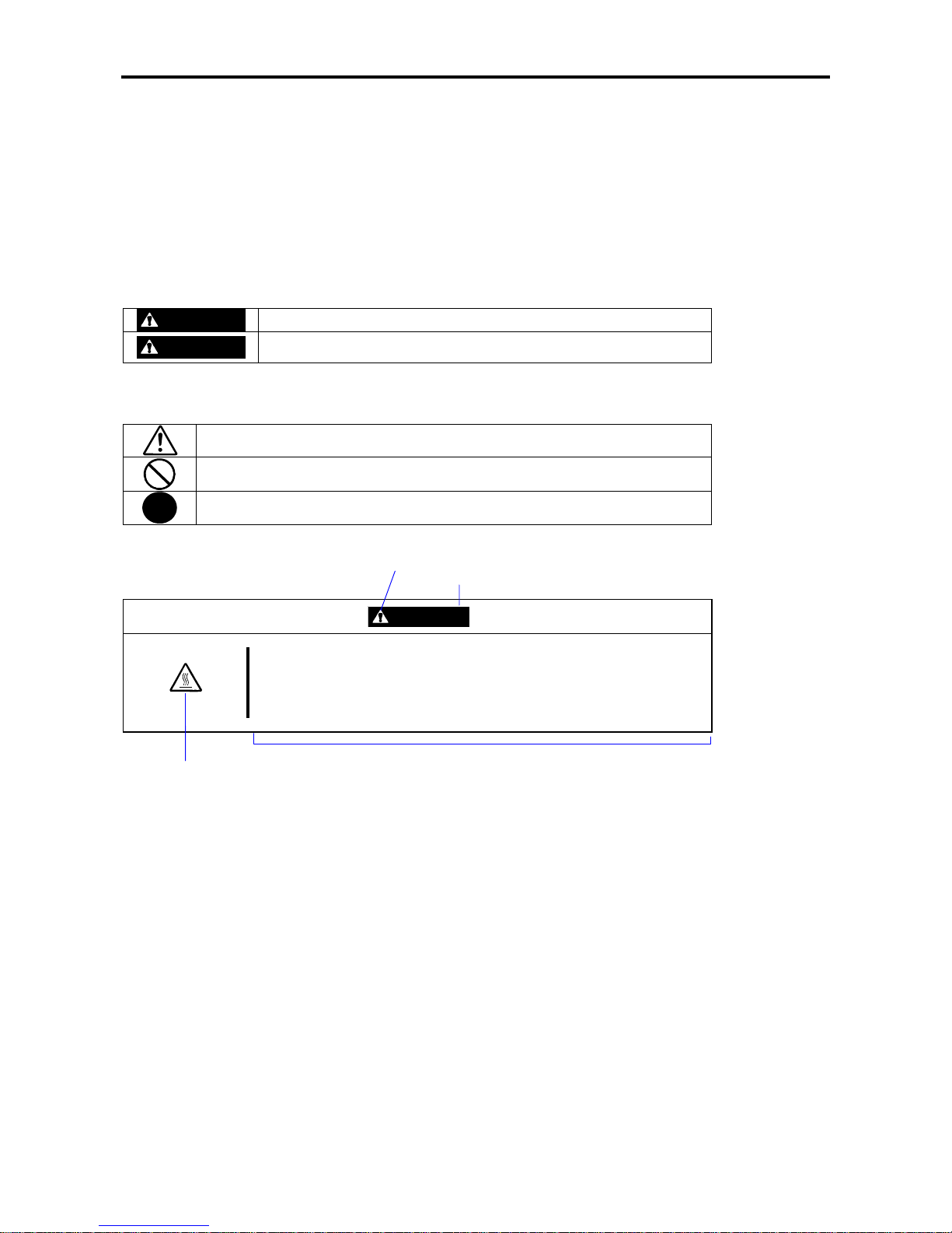
This guide and warning labels use “WARNING” and “CAUTION” to indicate a danger depending on the degree. These
terms are defined as follows:
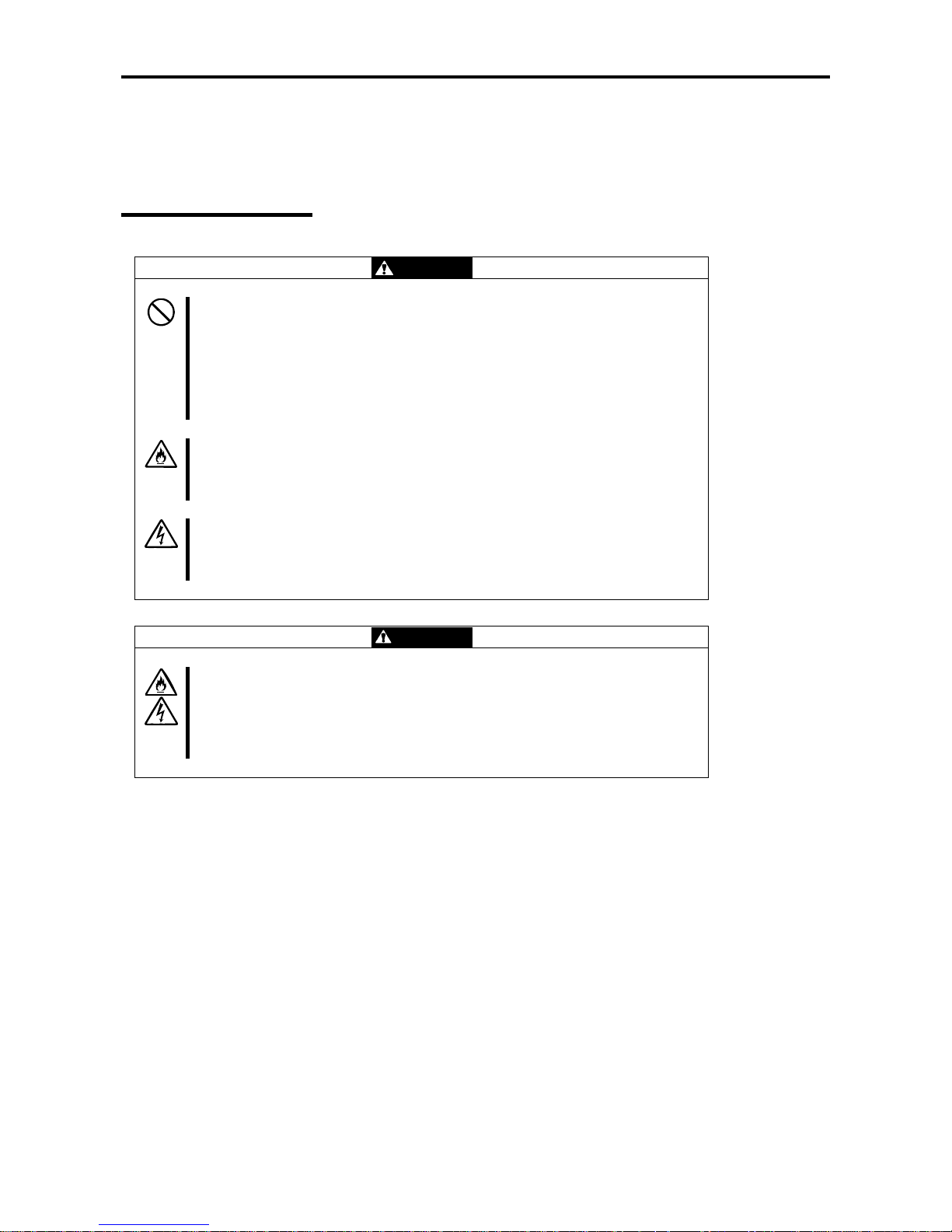
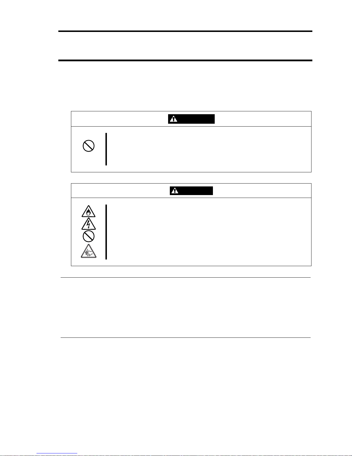
WARNING
Indicates a danger that could lead to a death or serious injury.
CAUTION
Indicates a danger that could lead to a burn, other injuries or damage to
physical assets.
This guide uses the following three types of symbols to give indications and precautions against a danger. They are
defined as follows:
Indicates that there is a risk of a danger. Each image symbolizes a particular type of
danger. (Attention)
Indicates what you must not do. Each image symbolizes a particular type of
prohibition. (Prohibited actions)
Indicates what you must do. Each image symbolizes a particular type of action
necessary to avoid a danger. (Mandatory actions)
(Example)
Symbol to draw attention
Term indicating a degree of danger
CAUTION
High temperature.
Immediately after the power-off, system components such as hard disk are
very hot. Wait the server to cool down completely before adding/removing
some component.
Symbol indicating a prohibited
action (may not always be
indicated)
Description of a danger
Page 9
ix
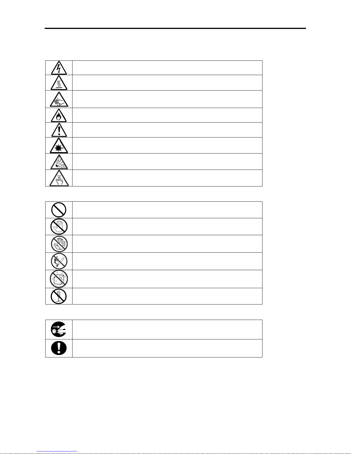
Symbols and its descriptions used in this User’s Guide and warning labels are as follows:
Attention
Indicates a risk of an electric shock.
Indicates a risk of a personal injury due to heat.
Indicates a risk of catching your fingers.
Indicates a risk of a fire or smoke.
Indicates a general precaution or warning that is not defined herein.
Indicates a risk of losing eyesight due to laser beam.
Indicates a risk of an explosion.
Indicates a risk of a personal injury.
Prohibited actions
Indicates a general prohibition that is not defined herein.
Do no touch the indicated area. There is a risk of an electric shock or fire.
Do not touch with wet hands. There is a risk of an electric shock.
Keep from flame. There is a risk of a fire.
Avoid using water or liquid nearby. If it spills on the equipment, there is a risk of an
electric shock or fire.
Do not disassemble, repair, or modify the equipment. There is a risk of an electric
shock or fire.
Mandatory actions
Unplug the server. There is a risk of an electric shock or fire.
Indicates a general action to take that is not defined herein. Make sure to follow the
instructions.
For detailed notes to set up the machine safely, refer to “NOTES FOR SAFE HANDLING” on page 1-2.
Page 10

x
NOTE: This equipment has been tested and found to comply with the limits for a Class A digital device, pursuant to
Part 15 of the FCC Rules. These limits are designed to provide reasonable protection against harmful interference when
the equipment is operated in a commercial environment. This equipment generates, uses, and can radiate radio
frequency energy and, if not installed and used in accordance with the instruction manual, may cause harmful
interference to radio communications. Operation of this equipment in a residential area is likely to cause harmful
interference in which case the user will be required to correct the interference at his own expense.
This class A digital apparatus meets all requirements of the Canadian Interference-Causing Equipment Regulations.
Cet appareil numérique de la classe A respecte toutes les exigences du Règlement sur le matériel brouilleur du Canada.
This system is classified as a CLASS 1 LASER PRODUCT. This label id located on the internal
DVD-ROM installed in your system.
NOTE: This product provides resistance against hardware faults with its redundant hardware modules. However, this
does not mean complete fault-tolerance is assured. For example, there is a risk of system down when:
– A fatal fault occurs in software.
– Both modules within a redundant hardware pair break down.
– A fatal fault occurs in a non-redundant component, such as the clock generator circuitry or the interconnect
backplane.
– The entire system is cut off from AC power.
Trademarks and Patents
EXPRESSBUILDER, NEC ESMPRO and DianaScope are registered trademarks of
NEC Corporation.
Microsoft, Windows, Windows Server, Windows NT, and MS-DOS are registered trademarks of Microsoft Corporation
in the United States and other countries.
Intel and Pentium are registered trademarks of Intel Corporation.
AT is a registered trademark of International Business Machines Corporation in the United States and other countries.
Adobe, the Adobe logo, Acrobat, and the Acrobat logo are trademarks of Adobe Systems Incorporated.
Datalight is a registered trademark of Datalight, Inc. ROM-DOS is a trademark of Datalight, Inc.
Xeon is a trademark of Intel Corporation in the United States. DLT and DLTtape are trademarks of Quantum
Corporation in the United States.
Mozilla is a registered trademark of Mozilla Foundation.
Netscape is a registered trademark of Netscape Communications Corporation in the United States and other countries.
Java is a registered trademark of Sun Microsystems, Inc in the United States and other countries.
All other product, brand, or trade names used in this publication are the trademarks or registered trademarks of their
respective trademark owners.
Microsoft Windows Server 2003 R2 Standard x64 edition operating system and Microsoft Windows Server 2003 R2
Enterprise x64 Edition operating system or Microsoft Windows Server 2003 Enterprise x64 Edition operating system
are called Windows Server 2003 x64 Edition for short. Microsoft Windows Server 2003 R2 32-bit Standard Edition
operating system, Microsoft Windows Server 2003 R2 32-bit Enterprise Edition operating system, Microsoft Windows
Server 2003 Standard Edition operating system and Microsoft Windows Server 2003 Enterprise Edition operating
system are called Windows Server 2003 for short. Microsoft Windows 2000 Server operating system, Microsoft
Windows 2000 Advanced Server operating system and Microsoft Windows 2000 Professional operating system are
called Windows 2000 for short. Microsoft Windows Vista Business operating system is called Windows Vista for short.
Microsoft Windows XP Professional x64 Edition operating system is called Windows XP x64 Edition for short.
Microsoft Windows XP Home Edition operating system and Microsoft Windows XP Professional operating system are
called Windows XP for short. Microsoft Windows NT Server network operating system version 3.51/4.0 and Microsoft
Windows NT Workstation operating system version 3.51/4.0 are called Windows NT for short. Microsoft Windows
Millennium Edition Operating System is called Windows Me for short. Microsoft Windows 98 operating system is
CLASS 1
LASER PRODUCT
Page 11

xi
called Windows 98 for short. Microsoft Windows 95 operating system is called Windows 95 for short. Names used with
sample applications are all fictitious. They are unrelated to any existing product names, names of organizations, or
individual names.
Avocent and DVC (DAMBRACKAS VIDEO COMPRESSION) are registered trademarks of Avocent US in the United
States and other countries.
ft remote management card, adopt the DVC technology of Avocent US.
The patent numbers for the DVC technology of Avocent US.
US Patent Number: 5,732,212/5,937,1 76/6,633,905/6,681,250/6,701,380 (others patents pending)
Taiwanese Patent Number: 173784
European Patent Number: 0 740 811
Notes:
(1) No part of this manual may be reproduced in any form without prior written permission of the manufacturer.
(2) The contents of this manual are subject to change without prior notice.
(3) The contents of this manual shall not be copied or altered without prior written permission of the manufacturer.
(4) All efforts have been made to ensure the accuracy of all information in this manual. If you find any part unclear,
incorrect, or omitted in this manual, contact the sales agent where you purchased this product.
(5) The manufacturer assumes no liability arising from the use of this product, nor any liability for incidental or
consequential damage arising from the use of this manual regardless of (4) above.
Page 12

xii
Preface
Welcome to the Fault Tolerant series.
Fault Tolerant series is a “fault-tolerant (ft)” server focusing on “high reliability” in terms of fault-tolerance, in addition
to “high performance,” “scalability,” and “general versatility” provided by our server series. In the event of trouble, its
dual configuration will allow the system to instantaneously isolate the failed parts to assure non-stop running; operation
will be moved smoothly from one module to the other, minimizing damage to it. You can use Fault Tolerant series in a
mission-critical system where high availability is required. By the use of Windows Server 2003 operating system, it also
provides outstanding openness for general-purpose applications, etc.
To make the best use of these features, read this User's Guide thoroughly to understand how to operate Fault Tolerant
series.
Page 13

xiii
About This User’s Guide
This User's Guide helps a user to properly setup and use the product. Consult this guide when you set up the product.
Keep this manual and the separate volume of User’s Guide handy.
This User's Guide is intended for users who have a good knowle dge on the basic use of Wind ow s operating systems and
general I/O devices such as a keyboard and mouse.
How to Use This User's Guide
This guide explains the procedures you should perform before you begin system operation after you purchased the
product. Read the guide in order from Chapter 1. If you perform procedures according to this guide, you will set up the
product properly.
Chapter 4 describes how to install the operating system. Chapter 5 describes post-installation procedures. Chapter 6
explains how to troubleshoot if you cannot set up the product properly. Refer to “SYSTEM REPAIR” on page 6-2 for
details about system configurations and repairs of this product. Refer to “TROUBLESHOOTING” on page 6-13 if you
feel you failed to set up the product.
See this User’s Guide for details of this product’s operation, and functions and operations of the hardware and the
system.
Additional Symbols
The following symbols are used throughout this User's Guide in addition to the caution symbols described at the
beginning.
IMPORTANT:
Important points or instructions to keep in mind when using the
server or software
CHECK:
Something you need to make sure when using the server or
software
TIPS:
Helpful information, something useful to know
Page 14

xiv
This page is intentionally left blank.
Page 15

Chapter 1
Before Using
This chapter includes information necessary for proper and safe operation of the server, the main unit and its accessories.
Go through this chapter before you start setup of the product.
Page 16
1-2
NOTES FOR SAFE HANDLING
The following section describes necessary information to use the product properly and safely.
Warning Label
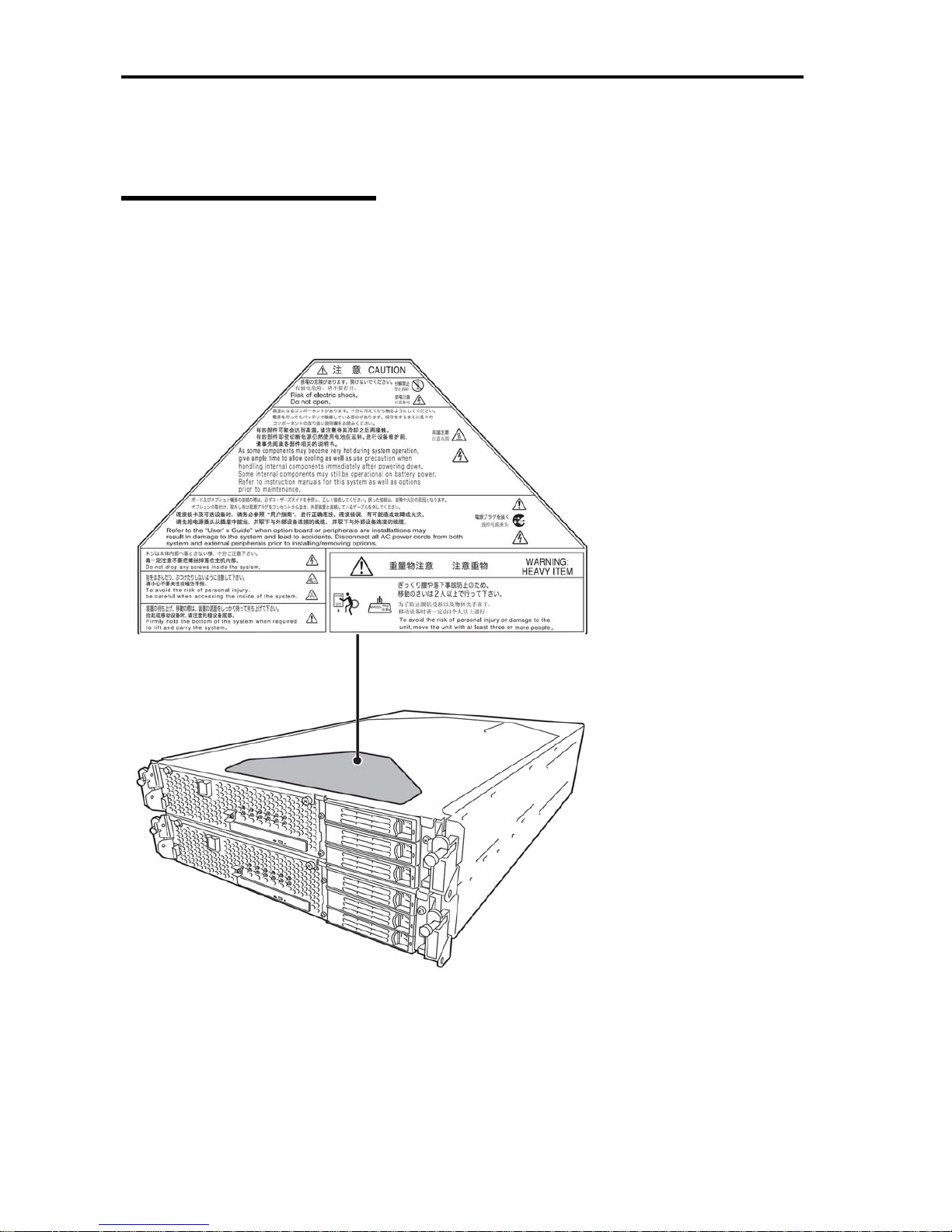
Warning label is placed in the certain part of the system so that the user stays alert to possible risks. Do not remove or
damage the label.
If this label is missing, about to peel off, or illegible, contact your sales agent.
The figures below show the location of this label on the server.
Front of Device
Page 17
1-3
PRECAUTIONS FOR SAFETY
This section provides precautions for using the server safely. Read this section carefully to ensure proper and safe use of
the server. For symbol meanings, see “Safety Indications” described in the previous section.
General
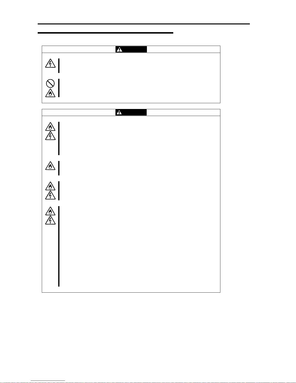
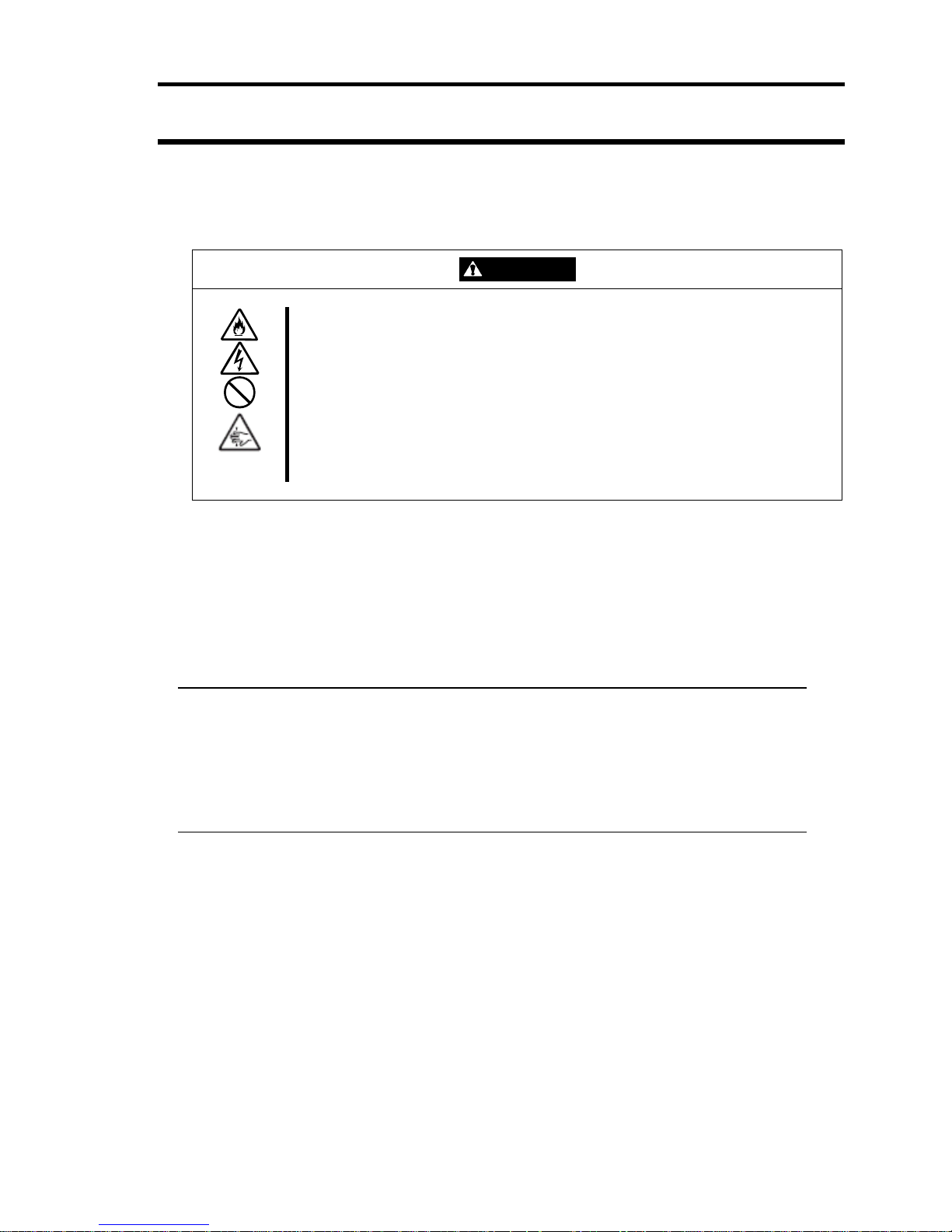
WARNING
Do not use the server in an operation where human lives ar e involved or hi gh rel iability
is required.
This equipment is not intended for use in controlling or use with facilities or systems
where human lives are involved or high reliability is required, including medical devices
or nuclear, aerospace, transportation, and traffic control facilities. The manufacturer
assumes no liability for any accidents or damage to phys ical assets resulting from the
use of this equipment in such systems or facilities.
Do not continue to use the server if you detect smoke, odor, or noise.
If the server emits smoke, odor, or noise, immediately flip off the POWER switch,
unplug the cords, and contact your sales agent. There is a risk of a fire.
Do not insert a wire or metal object.
Do not insert a wire or metal objects into a vent or disk drive slot. There is a risk of an
electric shock.
CAUTION
Prevent water or foreign objects from getting into the server.
Do not let water or foreign objects (e.g., pins or paper clips) enter the server. There is
a risk of a fire, electric shock, and breakdown. When such things accidentall y enter the
server, immediately turn off the power and unplug the cords. Contact your sales agent
instead of trying to disassemble it yourself.
Page 18
1-4
Use of Power Supply and Power Cord
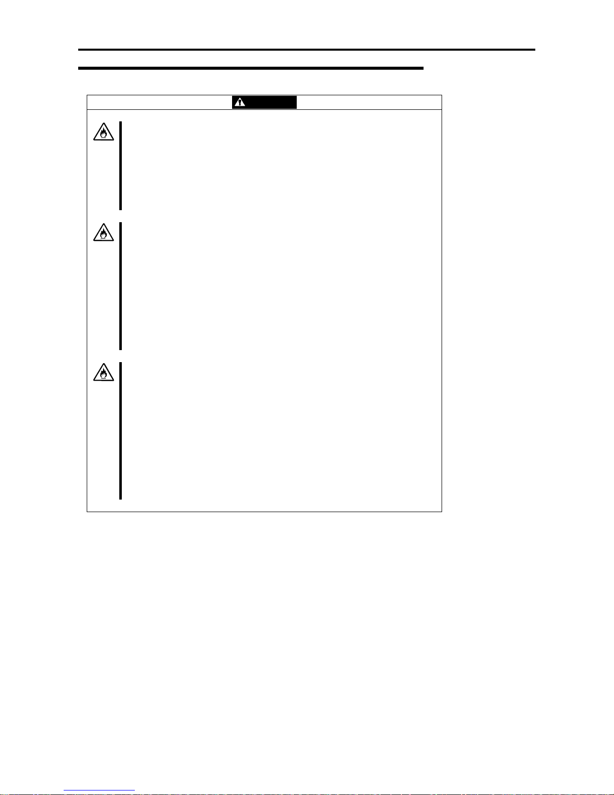
WARNING
Do not handle power plugs with a wet hand.
Do not plug/unplug power cords with a wet hand. There is a risk of an electric shock.
Do not connect the ground wire to a gas pipe.
Never connect the ground wire to a gas pipe. There is a risk of a gas explosion.
CAUTION
Do not plug the cords in nonconforming outlets.
Use wall outlets with specified voltage and power type. There is a risk of a fire or
current leakage.
Avoid installing the server where you may need extension cords. If the cords do not
meet the power specifications, there is a risk of overheating that could lead to a fire.
Do not plug too many cords in a single outlet.
If the rated current is exceeded, there is a risk of overheating that could lead to a fire.
Do not plug the cords insecurely.
Insert the plug firmly into an outlet. There is a risk of heat or fire due to poor contact. If
dust settles on the slots and it absorbs moisture, there is also a risk of heat or fire.
Do not use nonconforming power cords.
AC cord is to spend the thing of the next specifications:
You also have to observe the following prohibitions to prevent an electric shock or fire
caused by damage to the cords.
Do not pull on the cords.
Do not pinch the cords.
Do not bend the cords.
Keep chemicals away from the cords.
Do not twist the cords.
Do not place any object on the cords.
Do not use cords as bundled.
Do not alter, modify, or repair the cords.
Do not staple the cords.
Do not use any damaged cord. (Replace it with a new one of the same
specifications. For replacement procedures, contact your sales agent.)
Page 19
1-5
Installation, Relocation, Storage and Connection
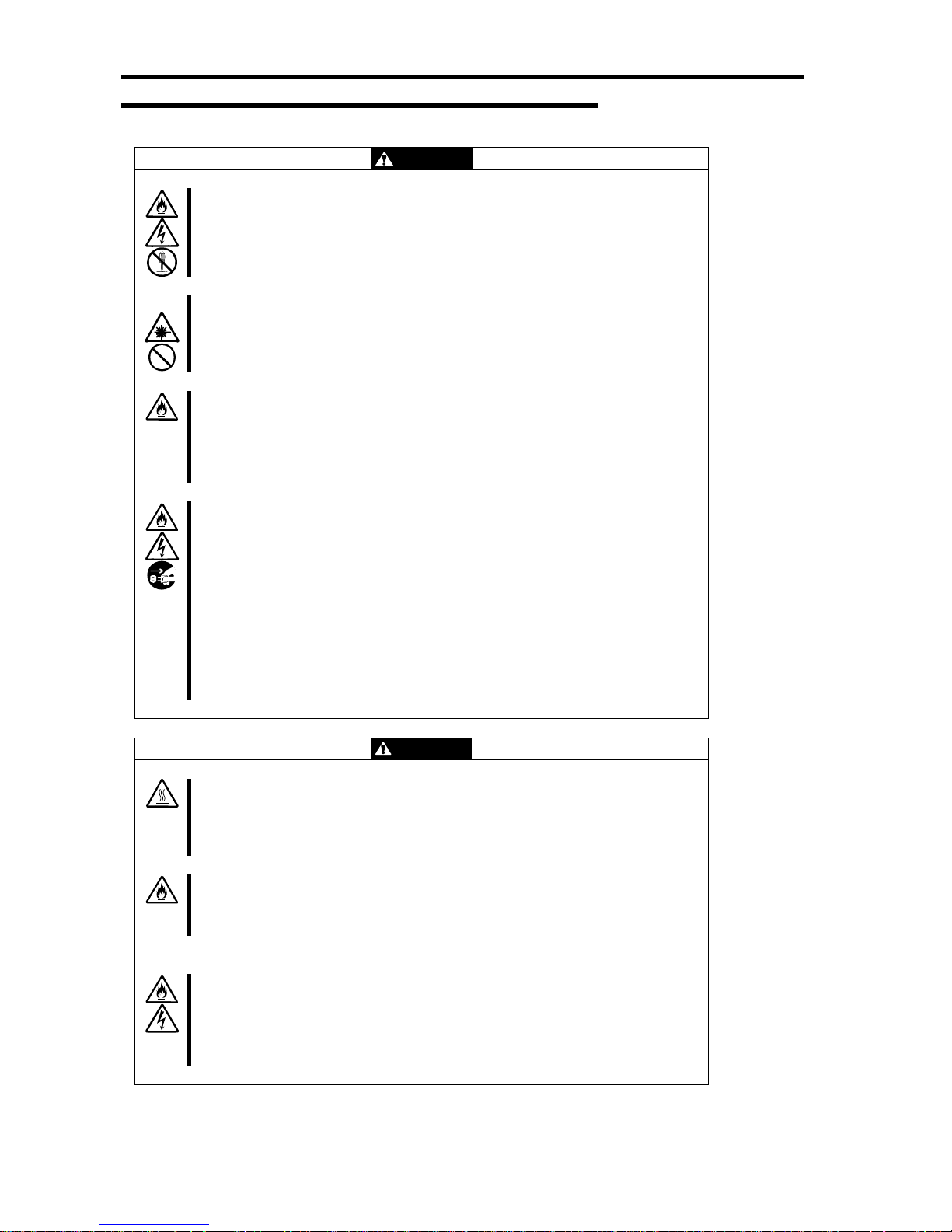
CAUTION
Do not install the server in an unsuitable place.
Install the server in such a place as specified in this User's Guide. Avoid the
following locations. There is a risk of a fire.
a dusty place
a humid place located near a boiler, etc
a place exposed to direct sunlight
an unstable place
Do not use or store this product in a corrosive environment.
Avoid the usage or storage of this product in an environment which may be
exposed to corrosive gases, such as those including but not limited to :
sulfur dioxide, hydrogen sulfide, nitrogen dioxide, chlorine, ammonia and/or ozone.
Avoid installing the Fault Tolerant series in a dusty environment or one that may be
exposed to corrosive materials such as sodium chloride and/or sulfur.
Avoid installing this product in an environment that may have excessive metal
flakes or conductive particles in the air.
Such environments may cause corrosion or short circuits within this product,
resulting in not only damage to this product, but may even lead to be a fire hazard.
If there are any concerns regarding the environment at the planned site of
installation or storage, please contact your sales agent.
Do not use any non-designated interface cable.
Use only interface cables designated by the manufacturer; identif y which
component or connector to attach beforehand. If you use a wrong cable or make a
wrong connection, there is a risk of short-circuit that could lead to a fire.
You also have to observe the following prohibitions about handling and connecting
interface cables:
Do not use any damaged cable connector.
Do not step on the cable.
Do not place any object on the cable.
Do not use the server with loose cable connections.
Do not use damaged cables.
Page 20
1-6
Cleaning and Handling of Internal Devices
WARNING
Do not disassemble, repair, or alter the server.
Unless described herein, never attempt to disassemble, repair, or alter the server.
There is a risk of an electric shock or fire as well as malfunction.
Do not look into the DVD-ROM drive.
The DVD-ROM drive uses a laser beam. Do not look or insert a mirror inside while the
system is on. A laser beam is invisible; if your eyes get exposed to it, there is a risk of
losing eyesight.
Do not detach a lithium battery yourself.
This equipment has a lithium battery. Do not detach it yourself. If the battery is
exposed to fire or water, it could explode.
When the lithium battery is running down and the server does not work correctly,
contact your sales agent instead of disassembling, replacing or recharging it yourself.
Disconnect the power plugs before cleaning the server.
Even though built-in options for the server can be replaced while the p ower cords are
connected to power source, be sure to follow the instructions described in this User’s
Guide. Do not touch any internal device of the server unless instructed by this User ’s
Guide. There is a risk of an electric shock.
Make sure to power off the server and disconnect the power plug from a power outlet
before cleaning or installing/removing internal optional devices. Touching any internal
device of the server with its power cords connected to power source may cause an
electric shock even if the server is off-powered.
Disconnect the power plug from the outlet occasionally and clean the pl ug with a dry
cloth. Heat will be generated if condensation is formed on a dust y plug, which may
cause a fire.
CAUTION
High temperature
Immediately after powering off the system, system components such as hard disk may
be very hot. Wait for the server to cool down completely before adding/removing
components.
Make sure to completely insert cables and boards.
Completely insert all power cords, interface cables and/or boards. An incompletely
inserted component may cause a contact failure, resulting in fire and/or smoke.
Protect the unused connectors with the protective cap.
The unused power cord connectors are covered with the protective cap to prevent
short circuits and electrical hazards. When removing the power cord connector from
the internal devices, attach the protective cap to the connector. Failure to follow this
warning may cause a fire or an electric shock.
Page 21
1-7
During Operation
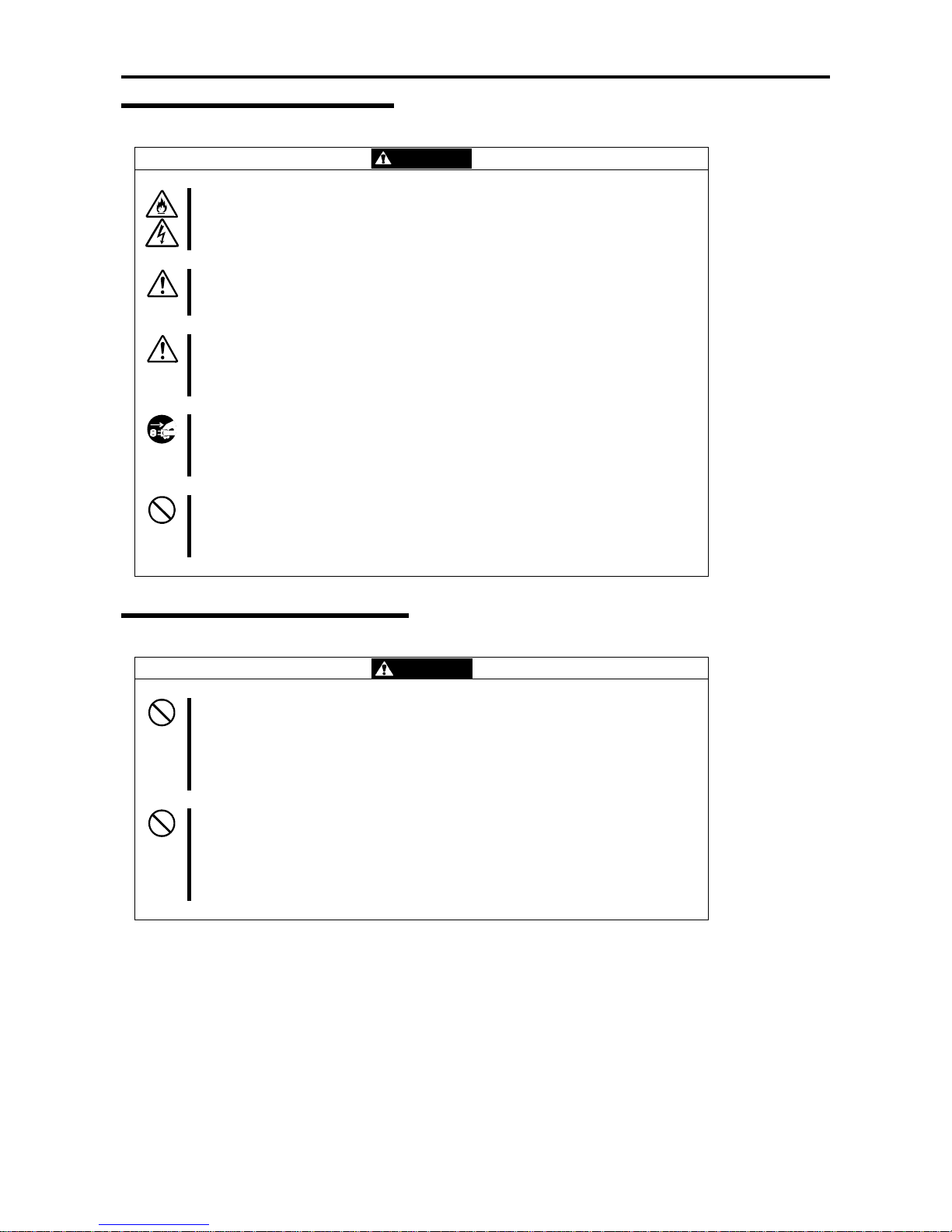
CAUTION
Keep animals away.
Keep animals away from the server. Animal’s waste or hair may get inside the server
to cause a fire or electric shock.
Do not place any object on top of the server.
The object may fall off to cause injuries, damage to hardware and/or a fire.
Do not leave the DVD tray ejected.
Dust may get in the server to cause malfunction. The ejected tray may also become a
cause of injuries.
Do not touch the server when it thunders.
Unplug the server when it threatens to thunder. If it starts to thunder before you unplug
the server, do not touch the server or cables. There is a risk of a fire or electric shock.
Do not use a cellular phone or pager around the server.
Turn off your cellular phone or pager when you use the server. Their radio waves may
cause the server to malfunction.
Rack-mount Model
WARNING
Do not install the server on a nonconforming rack.
Install the server on a 19-inch rack conforming to the EIA standard. Do not use the
server without a rack or install it on a nonconforming rack. The server may not function
properly, and there is a risk of damage to physical assets or injuries. For suitable
racks, contact your sales agent.
Do not use the server in an unsuitable place.
Do not install a server rack in an unsuitable environment.
Other systems also may be affected, and the rack may fall over to cause a fire or
injuries. For details about installation environment and quake-resistant engineering,
see the attached manual or contact your sales agent.
Page 22
1-8
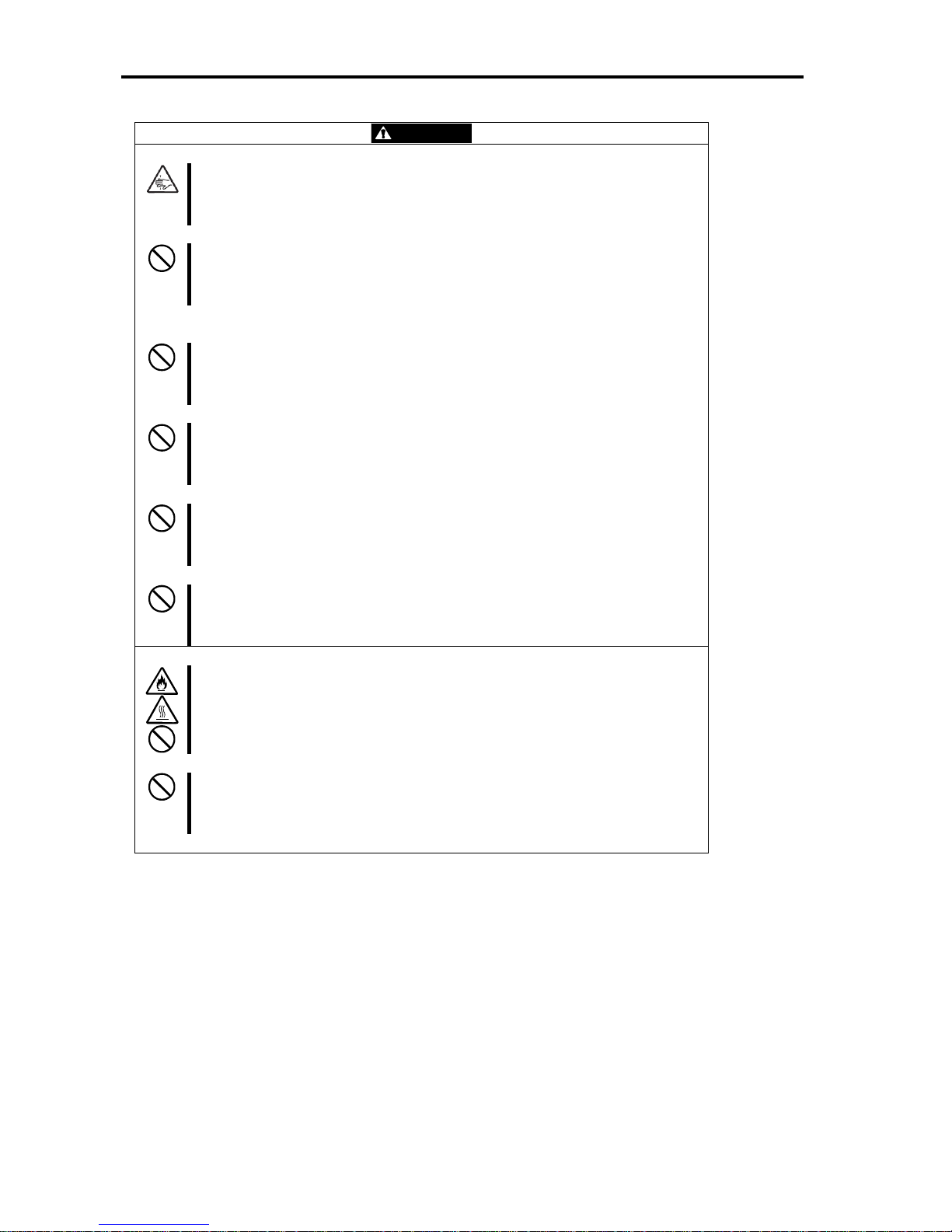
CAUTION
Be careful not to hurt your fingers.
Exercise great care not to hurt your fingers on the rail when you mount/d ismount the
server into/from the rack.
Carry or install the server by more than 3 people.
To avoid a risk of injuries, users should not attempt to carry or install the server into a
rack. Installation should be performed by trained maintenance personnel.
Do not install the server in such a manner that its weight is imposed on a single place.
To distribute the weight, use stabilizers or attach two or more racks. Unstable rack
may fall down to cause injuries.
Do not assemble parts alone.
It takes at least two people to mount doors and trays to a rack. If you handle them
alone, you may drop some parts to cause a breakage or injuries.
Do not pull a device out of the rack if the rack is unstable.
Before pulling out a device, make sure that the rack is fixed (by stabilizers or
quake-resistant engineering).
Do not leave more than one device pulled out from the rack.
If you pull out more than one device, the rack may fall down. You can only pull out one
device at a time.
Do not install excessive wiring.
To prevent burns, fires, and damage to the server, make sure that the rated load of the
power branch circuit is not exceeded. For more information on installation and wiring
of power-related facilities, contact your electrician or local power company.
Do not pull out a device during operation.
Do not pull out or remove a device while it is running. The re is a risk of malfunction
and a device may be detached from a rack to cause injuries.
Page 23

1-9
UNPACKAGING
This product and various accessories are in the special shipping box. Take them out from the box and check the
individual items. Store the box and unused accessories in a safe place.
Accessories
This product is shipped with various accessories. See the packing list to make sure everything is included and check the
individual items. If any component is missing or damaged, contact your sales agent.
Keep the accessories in a safe place. You will need them when you perform setup, addition of options, or
replacement of failed components.
To check EXPRESSBUILDER components, see the attached list.
Be sure to fill out and mail the software registration card that is shipped with the operating system.
Make backup copies of included floppy disks, if any. Keep the original disks as the master disks; use these
copies in operation.
Improper use of an included floppy disk or DVD may alter your system environment. If you find something
unclear, stop using them and contact your sales agent.
Page 24

1-10
(This page is intentionally left blank.)
Page 25

Chapter 2
About Operating System
This chapter gives essential information on the Windows system supported by the server and how to install it.
Page 26

2-2
INSTALLING Windows Server 2003 x64 Editions/
Windows Server 2003
For installing an operating system on the Fault Tolerant server series, refer to the below description.
IMPORTANT:
The Fault Tolerant server series is a precision instrument. You should ask maintenance personnel to install it.
Before performing the Fault Tolerant server series setup, contact your sales agent about the latest release of ft
Server Control Software.
About OS Installation
Read the notes here carefully before installing the operating system.
Operating System Supported by the Fault Tolerant server series
The operating system that the Fault Tolerant server series supports is as follows:
- Microsoft® Windows Server
TM
2003 R2 Enterprise x64 Edition (English), hereafter called “Windows Server
2003 x64 Editions.”
For more information on how to install Windows Server 2003 x64 Editions, refer to “Manual Setup.”
- Microsoft® Windows Server
TM
2003 R2 32-bit Enterprise Edition (English), hereafter called “Windows Server
2003.”
For more information on how to install Windows Server 2003, refer to “Express Setup.”
The Fault Tolerant server series does not support any operating systems other than the abov e (e.g., Windows Server
2003 Standard Edition, Windows 2000 or Wi ndows NT 4.0).
Page 27

2-3
About Windows Server 2003
Use the Express Setup program to install Windows Server 2003. Note the following at installation:
IMPORTANT:
Complete all the setups such as the memory expansion and the BIOS setting before installing Windows
Server 2003.
The software package, which is to be purchased separately, is also provided with the documentation for
installation. However, see this User's Guide for installation into this server.
After completing the Express Setup program, make settings for failure management (e.g., memory dump
(debug information) setting) according to Chapter 4.
The Express Setup is only applicable to Windows Server 2003; “Manual Setup” is applicable to Windows
Server 2003 x64 Editions. “Manual Setup” allows you to manually and individually install Windows Server
2003 x64 Editions, disk drivers and other utilities.
About Auto Installation of Utilities
The Express Setup installs the following utilities automatically.
Drivers and services for achieving duplicated ope rat ion
NEC ESMPRO Agent
The Express Setup program is exclusively used for the Fault Tolerant server series. To execute the setup program,
simply select the item [Express Setup] from the menu displayed when starting the system through the provided
“EXPRESSBUILDER.” The setup program automatically performs the complete setups from hardware internal
parameter/status settings to installation of the operating system (Windows Server 2003) and various utilities.
Use the Fault Tolerant server series setup program for the first installation and reinstallation of the operating system.
This program accomplishes complicate setups.
Page 28

2-4
(This page is intentionally left blank.)
Page 29

Chapter 3
Installing Server
This chapter describes requirements for using the product properly and safely, the setup procedures
to make Fault Tolerant Server series ready for use, and how to connect peripherals.
Page 30
3-2
INSTALLATION
This section describes installation of Fault Tolerant Server series.
Rack-mount Model
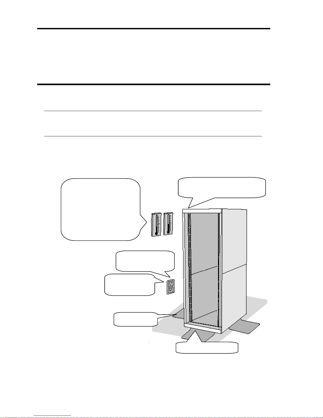
You can mount Fault Tolerant Server series on a rack that conforms to the EIA standards.
IMPORTANT:
Fault Tolerant Server series is a precision instrument. You should ask maintenance personnel
to install it.
Installing a rack
To install a rack, see the instruction that comes with the rack, or contact your sales agent or
maintenance personnel.
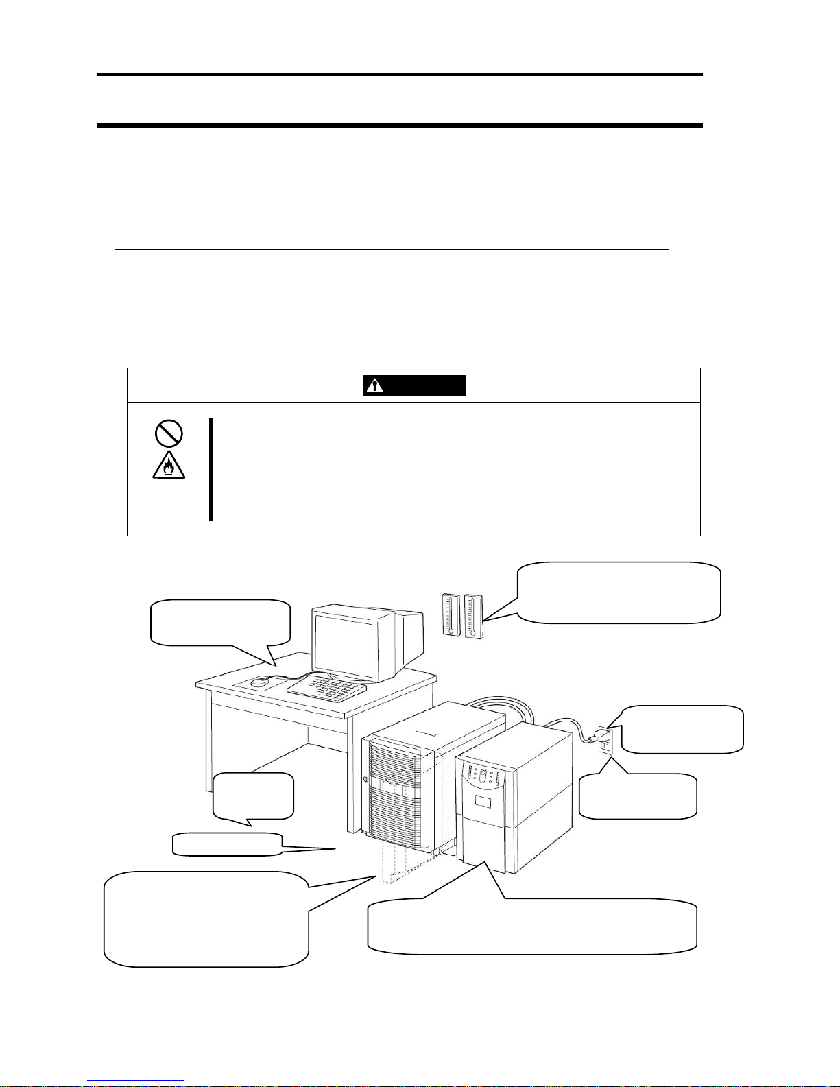
* It is recommended to use the server in a room where
temperature can be kept between 15 and 25ºC.
Wall outlet within the
reach of supplied power
cord.
100V - 120 V or 200V - 240 V
parallel bi-polar power outlet
with grounding
Space 40 cm or more on top, 1 m or more
on the front and rear, and 60 cm or more on
the right and left.
A room that can maintain the following
conditions:
[When operating]
Temperature: 10 to 35ºC*
Humidity: 20 to 80%
Temperature gradient: ±10ºC/hr
Atmospheric pressure: 749 to 1040hpa
[When not operating]
Temperature: 5 to 40ºC*
Humidity: 10 to 80%
Temperature gradient: ±15ºC/hr
Atmospheric pressure: 749 to 1040hpa
Level and reinforced
floor.
Place where the rack is
stabilized b
y
the stabilize
r
Page 31
3-3
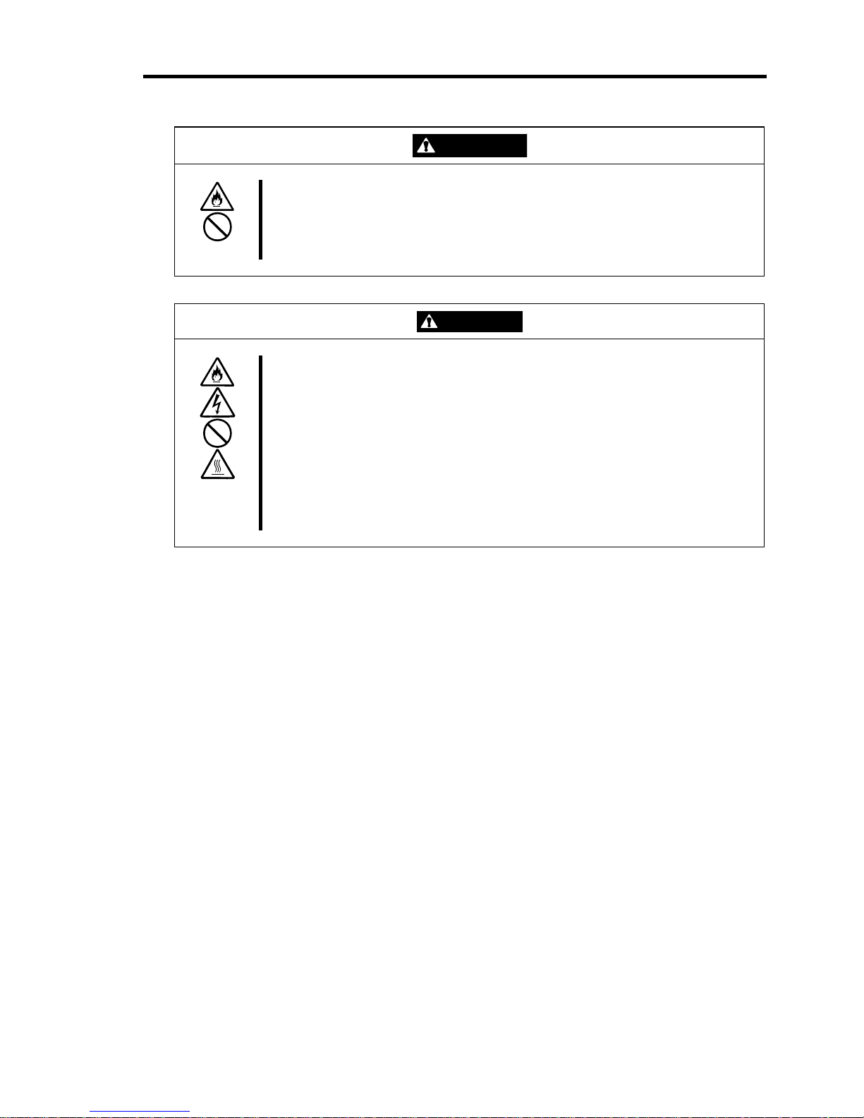
WARNING
Observe the following precautions to use the server safely. There is a risk of a
death or serious injury. For details, see “Notes for Safe Handling” in Chapter 1.
Do not install the server in non-designated places.
Do not connect the ground wire to a gas pipe.
CAUTION
Observe the following precautions to use the server safely. There is a risk of a
burn, personal injury, or damage to physical assets. For details, see “Notes for
Safe Handling“ in Chapter 1.
Do not carry or install a rack alone.
Do not install a rack in such a manner that its weight is imposed on a single
place.
Do not assemble or disassemble parts alone.
Do not pull a device out of the rack if the rack is unstable.
Do not leave more than one device pulled out from the rack.
Do not install excessive wiring.
Do not install Fault Tolerant Server series in such places as listed below. If you locate racks or
install the server in such places, the server may malfunction.
Place where you cannot pull out the components fully.
Place that cannot sustain the total weight of the rack and its components.
Place where you cannot use stabilizers or where you cannot perform installation without
quake-resistant engineering.
Place whose floor is uneven or inclined.
Place where temperatures change widely (near a heater, an air conditioner, or a refrigerator).
Place that is subject to intense vibration.
Place where corrosive gas (sodium chloride, sulfur dioxide, hydrogen sulfide, nitrogen
dioxide, or ozone) is generated, or a place that is close to chemicals or exposed to chemicals.
Place whose floor is covered with non-antistatic carpet.
Place that may be subject to falling objects.
Place that is close to some equipment that generates intense magnetic field (e.g., TV set,
radio, broadcasting/communications antenna, power transmission wire, and electromagnetic
crane). (If unavoidable, contact your sales agent to request proper shield construction.)
Place where the power cords of the server must be connected to outlets that share the outlet
of another device with large power consumption.
Page 32

3-4
Place that is close to some equipment that causes power noises (e.g., sparks caused by
power-on/off using a relay). If you must install the server close to such equipment, request
your sales agent for separate power cabling or noise filter installation.
Page 33
3-5
Installing the device to the rack
Install this device to the rack.
Installing the device to our company’s racks or to other company’s racks is explained in this section.
WARNING
Observe the following precautions to use the server safely. There is a risk of a
death or serious injury. For details, see “Notes for Safe Handling“ in Chapter 1.
Do not use the product with the unspecified rack.
Do not use the product at non-designated places.
CAUTION
Observe the following precautions to use the server safely. There is a risk of a
burn, personal injury, or damage to physical assets. For details, see “Notes for
Safe Handling“ in Chapter 1.
Do not install or remove a rack alone.
Do not install the server with the cover removed.
Do not squeeze your fingers in the product.
IMPORTANT:
Temperature increase inside the rack and airflow
If you install several components or the ventilation isn’t good inside the rack, the internal
temperature may increase due to heat emitted from the components. When the operating
temperatures of Fault Tolerant Server series (10 to 35°C) are exceeded, there is a risk of
malfunction. You must take adequate precautions and measures for airflow inside the rack as well
as in the room so that the internal temperature can be kept withi n t his ran ge du ri n g o per at i on.
Page 34
3-6
z Required tool
To install the device to the rack, a Phillips-head screw drive is required.
● Checking the place to install
Decide the place (height) to install. To keep
balance, install it as low as you can on the rack.
To install the rack, the height for 4U is required.
IMPORTANT:
To install this device to the rack, the space for 1U is required for installing the USB
compatible floppy disk drive, in addition to the space for 4U.
Next to the square hole of the rack, an imprinted mark is placed for 1U (This is the unit to show the
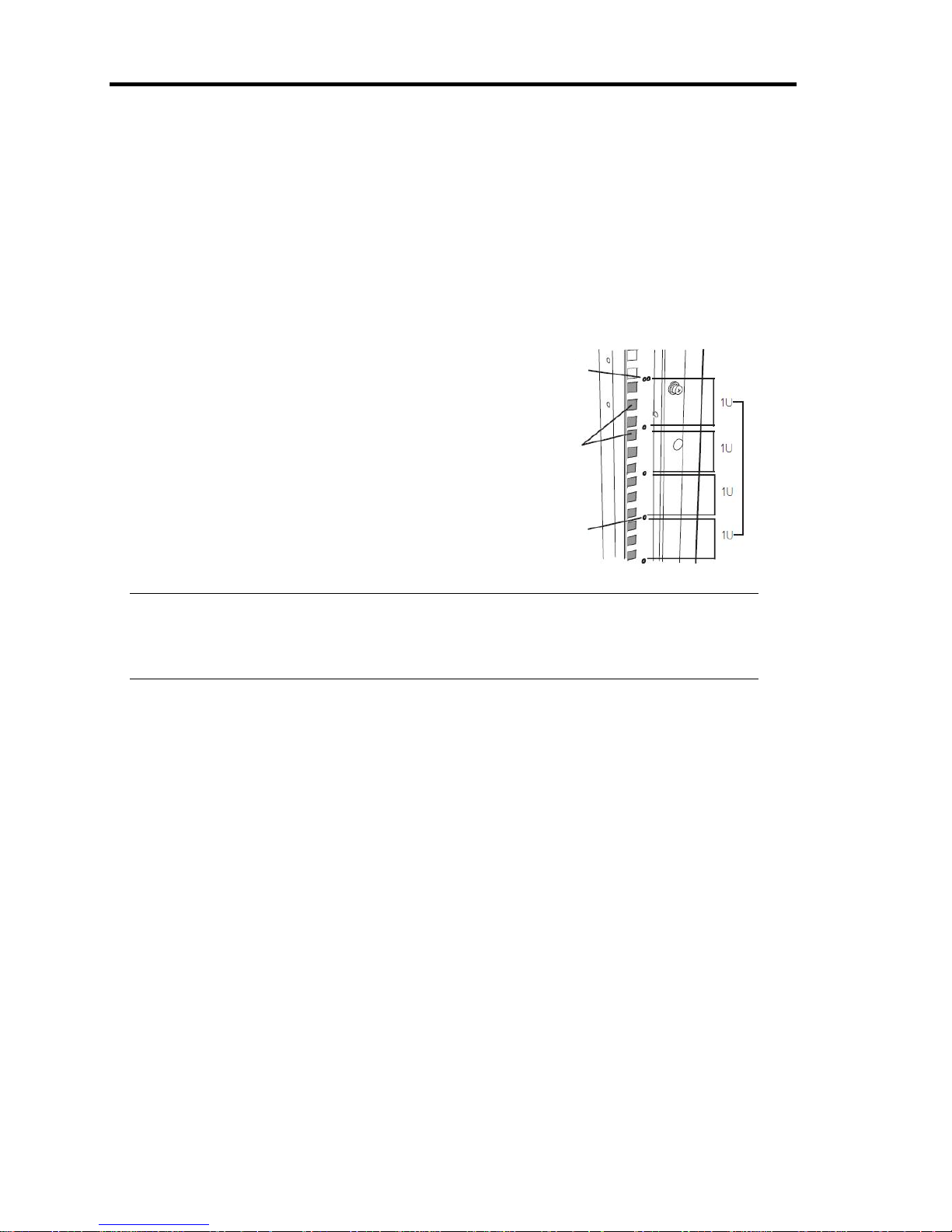
height of the rack). This device is as high as 4U (about 176 mm), so install it between the imprinted
marks that indicate the height of 4U.
Imprinted mark
Places to install
core nuts
Imprinted mark (2
imprinted marks fo
r
5Us)
4U (the height
for installing this
device)
Page 35
3-7
● Installing this device
Follow the steps below to set the 4U chassis to the rack.
IMPORTANT:
4U chassis weighs about 10 Kg. To mount, remove or replace it, be sure to hold it with two
or more people.
The following are the required accessories. Check if you have them all.
Tool Name Qty
- Bracket 2
- Panhead screw 4
- Panhead screw with washer 4
- Plate screw (short) 8
- Plate screw (long) 4
- Washer for plate screw 12
TIPS:
Core nuts (8 pieces) are not included. Use the core nuts that are attached to the rack.
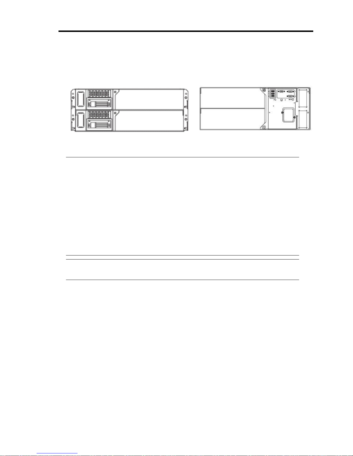
Front side of 4U chassis
Back side of 4U chassis
Page 36
3-8
1. If the rack has front and rear doors, read the instruction that comes with the rack, and open
them.
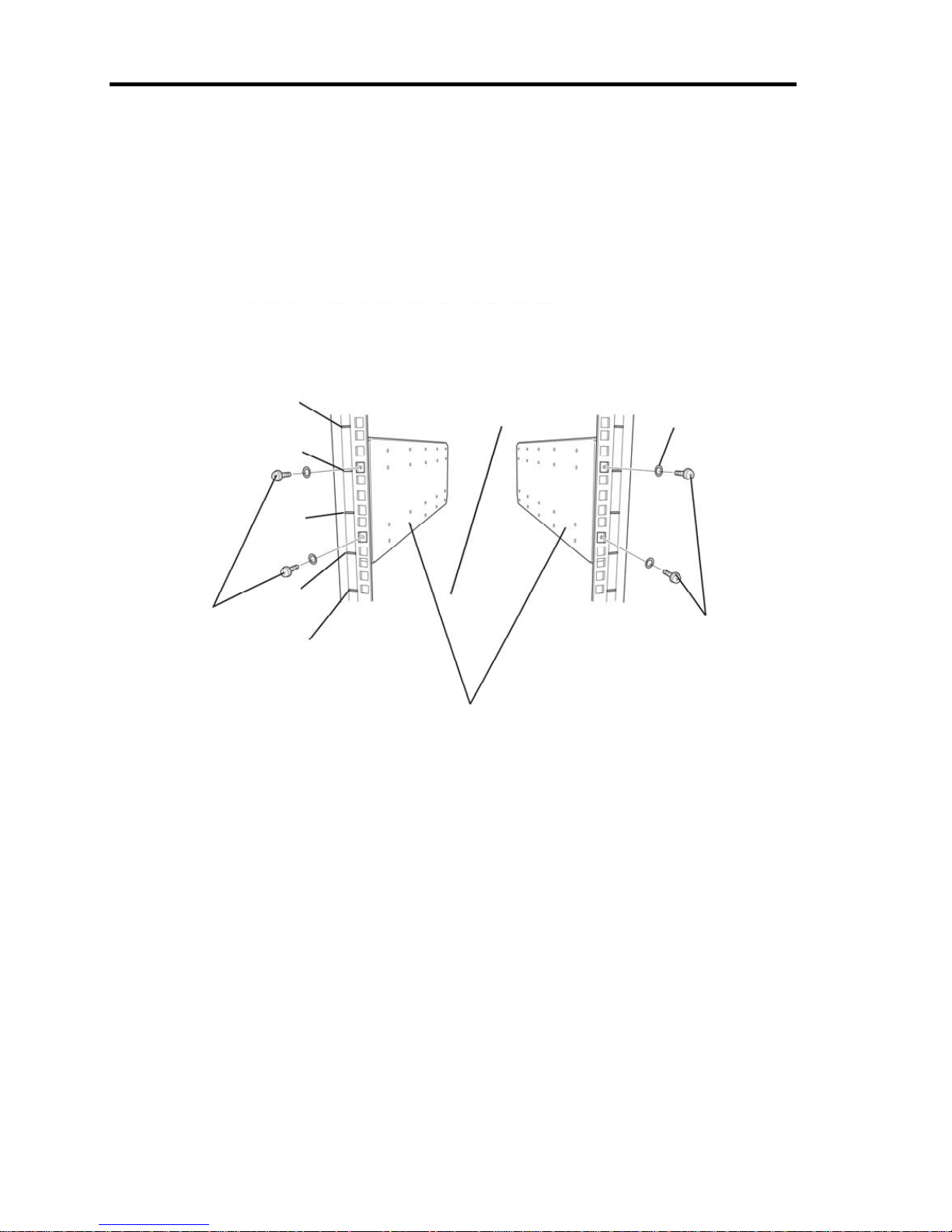
2. Install the brackets from the rear side of the rack. Install the brackets with its flat side facing
inside. Place them with the round screws with washers that come with the device
symmetrically (total: 4). Fasten the screws tentatively not tightly.
Panhead screws with
washers
4U
(top
of device
)
3U
2U
1U
Bottom o
f
device
Bracket (flat sides are facing inside)
Panhead screws with
washers
Plate
Page 37
3-9
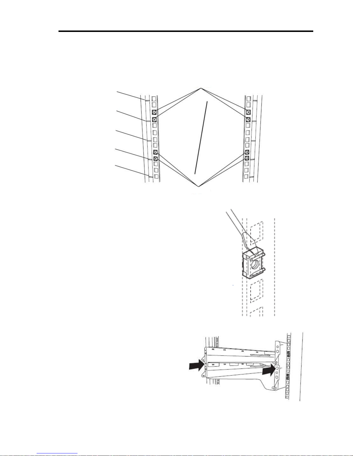
3. Fix the core nuts to the front side of the rack.
Attach them symmetrically (total: 8 core nuts).
Fix a core nut from inside of the rack.
Hook either of the clips of the core nut to a square
hole of the rack, and hook the other clip to a hole
by a flat-blade screwdriver.
4. Insert the 4U chassis from the front side
of the rack.
Core nuts
Core nuts
4U
(top of device)
2U
1U
Bottom of device
3U
Inside of
the rack
Outside of
the rack
Page 38
3-10
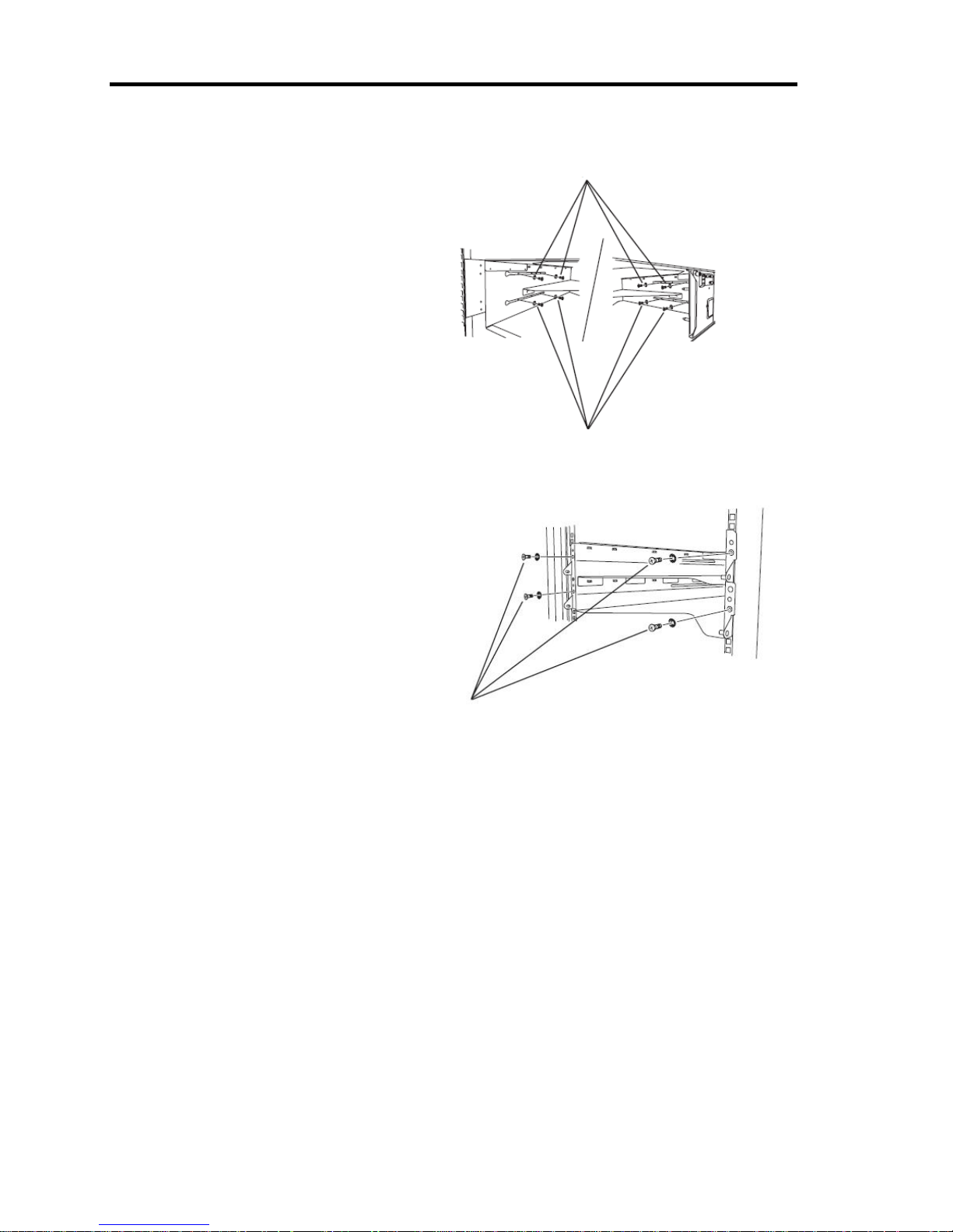
5. Tentatively fasten the washers and plate
screws (short) to the 4 places on the front
and back sides (total: 8) from the rear.
6. Fasten tightly the washers and round
screws (long) to the 2 places on the left
and right sides (total: 4) from the front.
Washers and plate screws (short)
Washers and plate screws (short)
Washers and plate screws (long)
Page 39
3-11
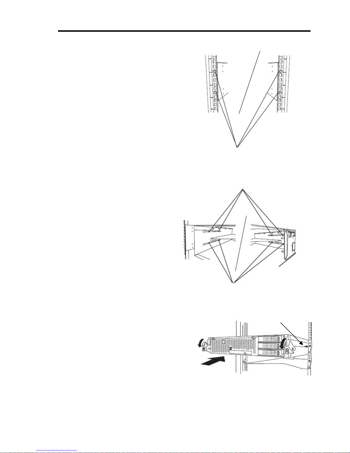
7. Fasten tightly the 4 round screws on the back
side and the 8 plate screws on the side panels
(which you fastened tentatively).
8. Mount the CPU/IO module 0.
Mount the module while lowering the lock so
the module stacks on the way.
Panhead screws on the side
panels
Plate screws on the side panels
Plate screws on the side panels
Lock
Page 40
3-12
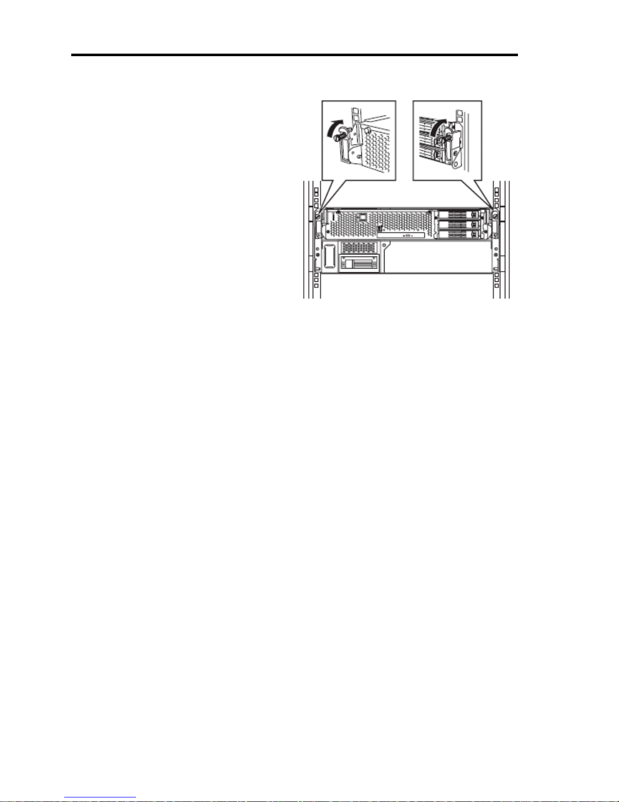
9. Fasten the levers on the left and right sides
with screws.
10. Mount the CPU/IO module 1 in the same way.
Page 41
3-13
Unmounting the device from the rack
Follow the steps below and unmount the device from the rack.
CAUTION
Observe the following precautions to use the server safely. There is a risk of a
burn, personal injury, or damage to physical assets. For details, see “Notes for
Safe Handling“ in Chapter 1.
Do not carry or install a rack alone.
Do not squeeze your fingers in the product
Do not impose a weight on the device when it is pulled out from the rack.
Do not pull a device out of the rack if the rack is unstable.
Do not leave more than one device pulled out from the rack.
Do not pull the device from the rack while it is operating.
1. Check that the device is powered off, and remove all the power cords and interface cables that
are connected to the device.
2. Remove the front bezel.
3. Loosen the screws on the left and right sides of the front panel of the CPU/IO module and
release the lock by pulling the ejector toward you.
4. Pull out the CPU/IO module gently from the rack.
IMPORTANT:
- When you pull out the device, do not load anything on its top. It is dangerous, since the
device becomes unstable and it may fall.
- Do not hold the handle on the front side or the convex part on the back side. To move
the device, hold the bottom.
- Since the device is locked and can not be pulled out, pull it out after releasing the lock
by lowering the lock on the side of the CPU/IO module.
5. Hold tightly when you unmount 4U chassis from the rack,.
To remove the mechanical parts of the rack, see the installation procedure.
Page 42
3-14
INSTALLING the Tower Conversion Kit
This section describes how to install the rack-mount model of Fault Tolerant Server series without
using the dedicated rack.
IMPORTANT:
Fault Tolerant Server series is a precision instrument. You should ask maintenance
personnel to install it.
Select a suitable site for tower model.
CAUTION
Observe the following precautions to use the equipment safely. There are risks
of a burn, injury, or damage to physical assets. For details, see “Notes for Safe
Handling“ in Chapter 1.
Remove all modules before moving the equipment.
Do not install the equipment in non-designated places.
* It is recommendable to use the server in a
room where temperature can be kept
between 15 and 25ºC.
Wall outlet within the
reach of supplied
power cord.
Uninterruptible Power Supply (UPS) to prevent momentary
voltage drop due to power failure or lightning *
* Optional. UPS is recommended for best use of features of the
Fault Tolerant Serve
r
series.
Close enough to connect
the keyboard and the
display.
Floor or a level
and robust
desk or table
Clean and tidy room
Location with an enough open space to
fully open the front bezel, at least 1 m
from the front, 50 cm .from the rear, and
15 cm from the sides of the server (The
front bezel extrudes about 50 mm from
the right side of the server when fully
o
p
ened.)
Room that can maintain the following
conditions during server operation:
Temperature: 10 to 35ºC*
Humidity: 20 to 80% (non-condensing)
AC 100V parallel
bi-polar power outlet
with grounding
Page 43
3-15
Do not install Fault Tolerant Server series in such places as listed below. Otherwise, the server may
malfunction.
Place where temperatures change widely (near a heater, ai r conditione r, or refrigerator).
Place that is subject to intense vibration.
Place where corrosive gas (sodium chloride, sulfur dioxide, hydrogen sulfide, nitrogen dioxide,
or ozone) is generated, or a place that is close to chemicals or exposed to chemicals.
Place whose floor is covered with non-antistatic carpet.
Place that may be subject to falling objects.
Place where you may step or trip on the power cords or interface cables.
Place that is close to some equipment that generates intense magnetic field (e.g., TV set, radio,
broadcasting/communications antenna, power transmission wire, and electromagnetic crane). (If
unavoidable, contact your sales agent to request proper shield construction.)
Place where the power cord of the server must be connected to an AC outlet that shares the
outlet of another device with large power consumption.
Place that is close to some equipment that causes power noises (e.g., sparks caused by
power-on/off using a relay). If you must install the server close to such equipment, request your
sales agent for separate power cabling or noise filter installation.
It takes at least three people to carry the server; hold it firmly by its bottom and place it slowly on
the selected site.
IMPORTANT:
Do not hold the front bezel to lift it, or it may detach, fall down, and break the server.
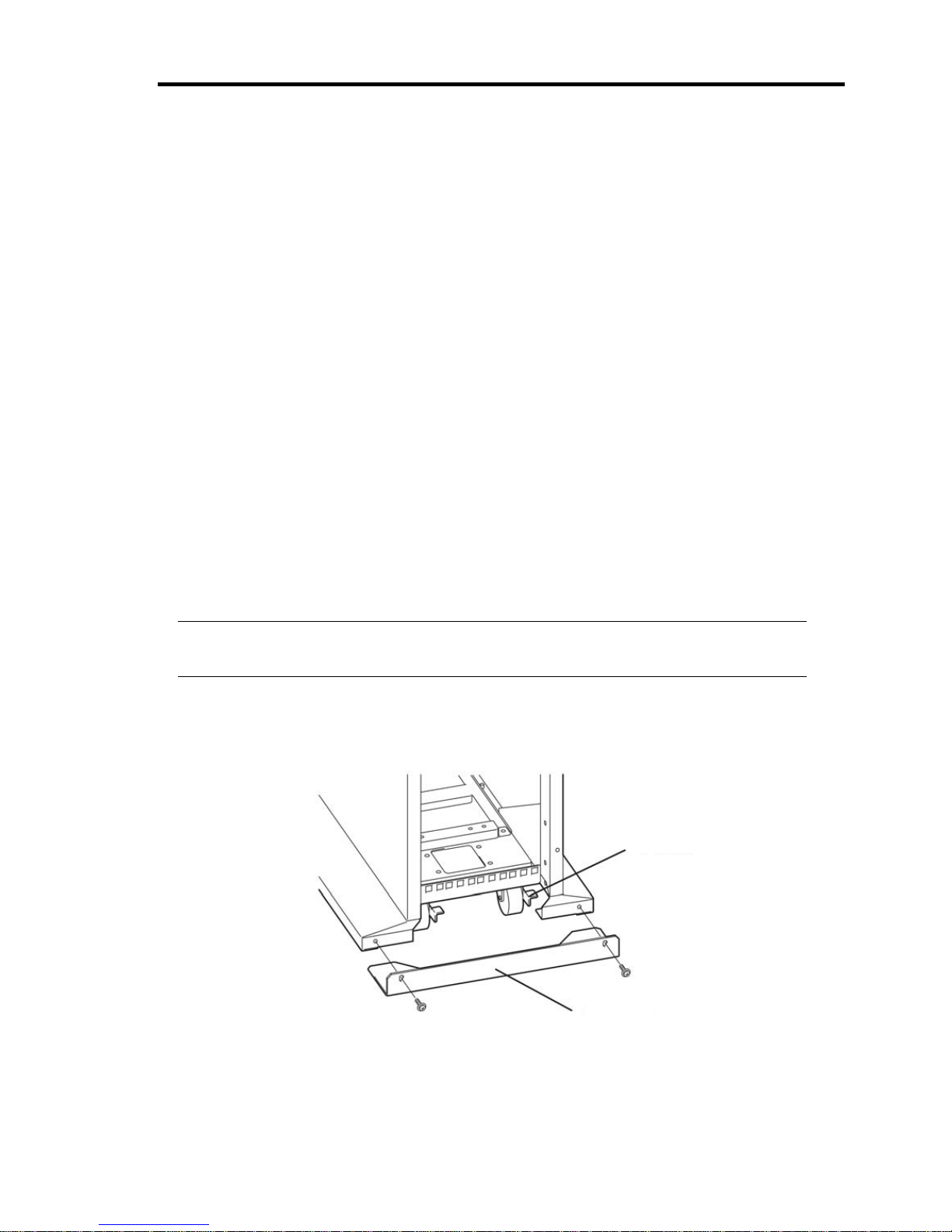
After placing the main cabinet, lock its two front casters out of four and screw the attached four
stabilizers on the cabinet adjusting their height.
Screws
Stabilizer
Lock lever
Page 44
3-16
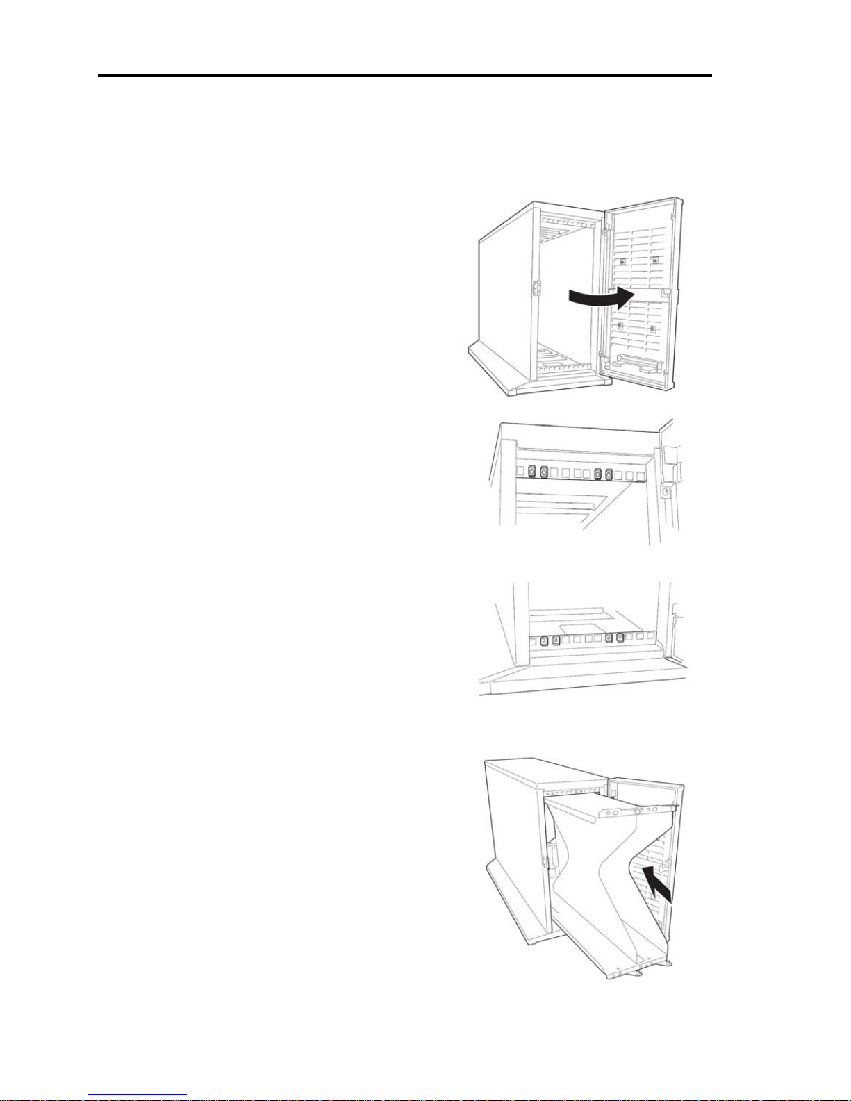
Steps to Install the Rack-mount Model to the Tower Conversion Kit
Follow the procedure below to install the devices to the tower conversion kit.
1. Open the front door of the tower conversion kit.
If the door is locked, use the server-accessory key
to unlock.
2. Confirm the spots to fix 8 core nuts on the front
of the chassis.
See the figure on the right for where to fix
the core nuts
(4 on the front top and 4 on the front bottom.)
3. Insert the bracket from the front of the conversion
kit. Tuck the bracket firmly to the back.
Tower conversion kit (on the front bottom)
Tower conversion kit (on the front top)
Page 45
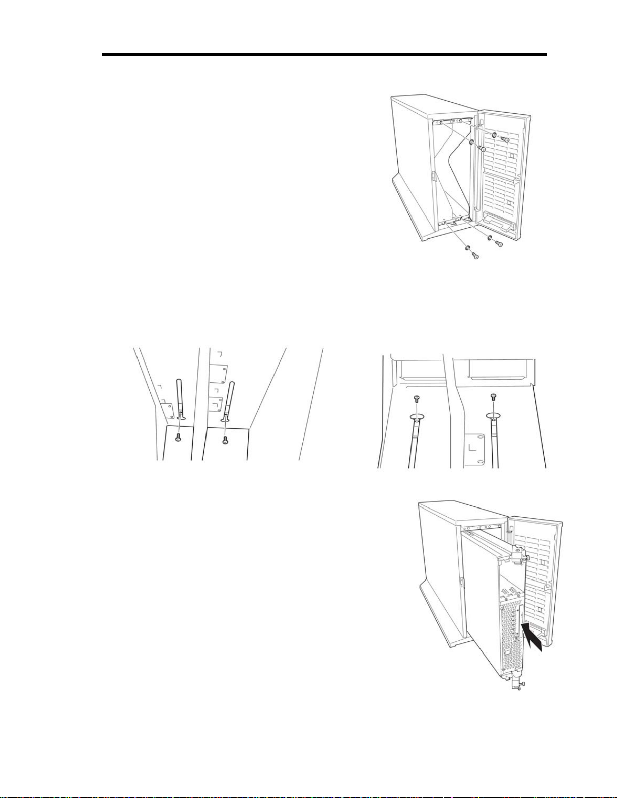
3-17
4. Fix the bracket with four washers and countersunk
screws (long ones), two at the top and two at the
bottom.
5. Fix the bracket with 4 washers and countersunk screws. See the figure on the right for where
to fix the screws (2 screws for the backside on the top, and 2 for the bottom of the tower
conversion kit).
6. Insert the device slowly and securely into the bracket.
Top (toward the backside) Bottom (toward the backside)
Page 46
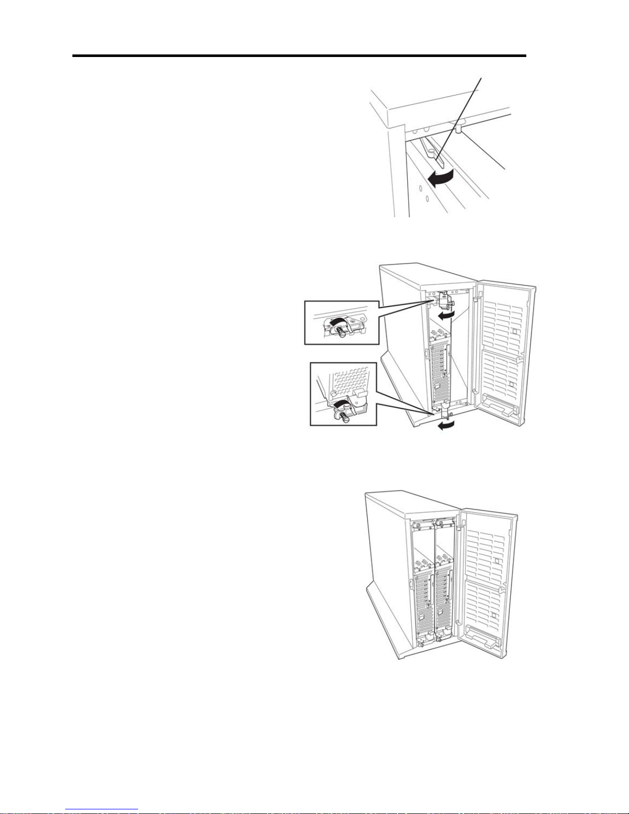
3-18
If it becomes rocked and cannot insert any further, push and
keep the rock lever to the left as push the device further inside.
7. Close the lever on the top and the bottom
of the device. Fix the device to the bracket
with clinchers.
8. Take steps 6 to 8 to fix the other device to the bracket.
Lock lever
Page 47
3-19
Connect peripheral devices to Fault Tolerant Server series
The server provides connectors for a wide variety of peripheral devices on its front and rear.
The figure on the next page illustrates available peripheral devices for the server in the standard
configuration, and locations of the connectors for the devices. After connecting the peripheral
devices, connect the provided power cords with the server, and then plug the power cords into the
power outlet.
WARNING
Observe the following precautions to use the server safely. There is a risk of a
death or serious injury. For details, see “Notes for Safe Handling“ in Chapter 1.
Do not hold the power plug with a wet hand.
Do not connect the ground wire to a gas pipe.
CAUTION
Observe the following precautions instructions for the safe use of the
equipment. There is a risk of a burn, personal injury, or damage to physical
assets. For details, see “Notes for Safe Handling“ in Chapter 1.
Do not plug the power cord in a nonconforming outlet.
Do not plug too many cords in a single outlet.
Do not plug the cord insecurely.
Do not use nonconforming power cords.
IMPORTANT:
Power off the server before connecting peripheral devices, with the exception of
peripherals with USB interface. Connecting a powered peripheral device to the powered
server will cause malfunctions and failures.
To connect a third-party peripheral device or interface cable to the server, check with
your sales agent to see if they are compatible with Fault Tolerant Server series. Some
third-party devices may not be used with the server.
The total cable length of SCSI device connections is up to 6 m, including the internal
SCSI cables.
The serial port connectors are reserved for maintenance.
Place the USB floppy disk drive on the server. Space of 1U is needed to put it on the
server.
Page 48
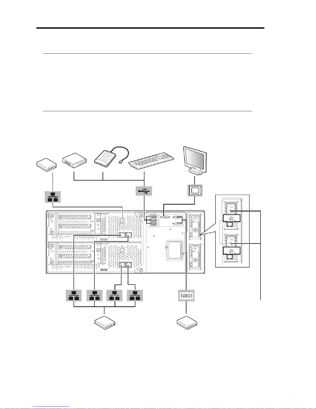
3-20
IMPORTANT:
Connection of optional devices
In the case of standard configuration, you need to complete setup of the operating
system before mounting optional PCI cards or har d di sks that you purchased
separately.
If a Fiber Channel Controller is mounted, be sure to connect cables to the FC array unit
before going on to the next step.
USB floppy disk
drive
USB connection
modem
Keyboard
(via keyboard hub to
USB mouse)
Display
Back of
the device
Hub
(multiport repeater)
To a 1000Mbps network
Serial Interface
Connect the device with the
serial interface
(This cannot be used since it is
for maintenance.)
LAN port
(VTM)
(Connect
only when using
the ft Remote
Management
Card
)
A
FTER every peripheral device is
connected, insert the power cord
into a socket. the outlet.
Page 49
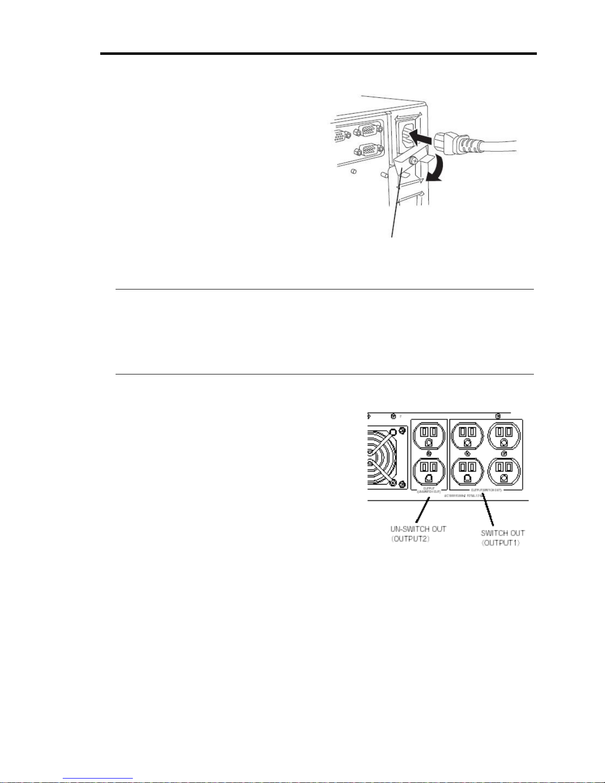
3-21
Rotate the stopper clockwise, and insert the
power cords to the AC inlets of the power unit.
Connect the plug at the other end of the power
cord to a wall outlet with parallel double-pole
grounds provided or to an uninterruptible power
supply (UPS).
To use the functions of the server, you should
connect the server to the UPS.
IMPORTANT:
Be sure to use both of the power cords to make the server fault-tolerant.
After connecting the power cords, wait at least 30 seconds before pressing the power
switch.
By pressing the power switch, the power switch’s fans starts to rotate.
To connect the power cords from the server to an
uninterruptible power supply (UPS), use service outlets on
the rear of the UPS.
The UPS service outlets are categorized into two groups:
SWITCH OUT and UN-SWITCH OUT. (They may be
called “OUTPUT1“ and “OUTPUT2“.)
To restrict the power supply from
ESMPRO/AutomaticRunningController, connect the
power cable to SWITCH OUT.
For constant power supply, connect the power cords to a
UN-SWITCH OUT outlet. (Connect the modem that is in
service for 24 hours to this outlet.)
When the power cords from the server are connected to a UPS, change the BIOS setup of the server
to link with power supply from the UPS.
Select [AC-LINK] from [Server] on the BIOS setup utility and change parameters. See the separate
volume of User’s Guide for details.
<Example>
Stopper
Page 50

3-22
(This page is intentionally left blank.)
Page 51

Chapter 4
Windows Setup
This chapter describes procedures such as configuring OS Boot Monitoring function, setting dual
LAN configuration, and setting dual disk configuration.
Page 52

4-2
Before starting Setup
Read this section before starting setup.
This chapter describes two types of setup.
Procedures to Install and Reinstall the Windows OS
Installing and Reinstalling Windows Server 2003 x64 Edition
“Manual Install” is required to install/reinstall OS (Windows), the disk drivers and other utilities
manually and individually.
Installing Windows Server 2003
Use EXPRESSBUILDER to install/reinstall Windows Server 2003.
“Express Setup” is the setup program that is specific to Fault Tolerant Server series.
EXPRESSBUILDER DVD, a server accessory, runs this setup program. Express Setup enables
automatic install of Windows Server 2003 and other various utilities.
Refer to “Procedure to Install and Reinstall OS.” Use this setup step if you want to reinstall OS or
use the HDD with a partition setting that is different from the default partition setting.
Page 53
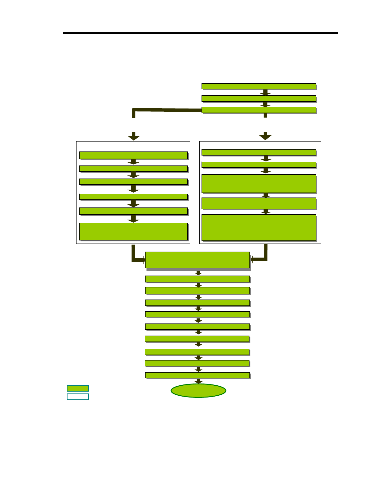
4-3
SETUP FLOW
Step 1 Start the OS reinstallation setup procedure
Step 2 Prepare the OS reinstallation setup
Step 3 Disable OS Boot Monitoring Function
Set [EXPRESSBUILDER] DVD
Create [OEM-Disk]
Specify the size of the partition for OS installation
Prepare for Windows Server 2003 R2 32-bit Enterprise
Editions installation and ft Server Control Software
installation
Set OS (Windows) CD-ROM
Install driver in [OEM-Disk]
Start the OS installation
Apply [System Update]
Install ft Server Control Software
and
N
EC ESMPRO/ServerAgen
t
Set Windows Server 2003 R2 32-bit Enterprise Edition
CD-ROM
Automatic installation of following software:
Windows Server 2003 R2 32-bit Enterprise Edition
ft Server Control Software, ESMPRO
Server/Agent
Set the EXPRESSBUILDER CD-ROM Windows
Server 2003 x64 Editions (Manual Setup)
Set the EXPRESSBUILDER CD-ROM Windows
2003 (Express Setup)
Step 4B Manual Setup
: Entered or selected by the user
: Proceeds automatically
Setup
Step 5 Install Windows Server 2003
Service Pack
Step 7 Set Dual Disk Configuration
Step 6 Set Dual LAN Configuration
Step 8 Update Software
Step 9 Connect and Configure Options
Step 10 Create Volume
Step 12 Enable OS Boot Monitoring
Step 13 Make Settings for Failure
Step 14 Back up System Information
This flow chart illustrates the flow of the setup
p
rocedures for the Fault T olerant Server.
Step 4A Express Setup
Step 11 Set Network for NEC ESMPRO
Page 54

4-4
Step 1: Procedure to Install and Reinstall OS
The following explains OS install and reinstall:
IMPORTANT:
“Express Setup” deletes all data on the disk used for installation/reinstallation, as
“Express Setup” formats the entire disk. If there is any data partition other than the
system partition containing OS for reinstallation, you must back up the important
data in the data partition first and then start “Express Setup.”
Do not apply service packs to Fault Tolerant Server series based on your judgment.
If you want to apply service packs, contact your sales agent for the latest application
and apply service packs to Fault Tolerant Server series.
Following items are required for install/reinstall:
For Windows Server 2003 x64 Editions
EXPRESSBUILDER DVD
ft Server Control Software UPDATE CD-ROM
This CD-ROM is used to update ft Server Control Software; it may not be shipped with the
equipment. (Not included if “EXPRESSBUILDER”DVD contains the latest version of
software programs at the time of shipment.)
Microsoft® Windows Server™ 2003 R2, Enterprise x64 Editions Disk 1
(hereinafter referred to as “Windows Server 2003 x64 Editions CD-ROM”)
Microsoft® Windows Server™ 2003 R2, Enterprise x64 Edition Disk 2
(One set consists of 2 disks.)
Windows Server 2003 x64 Editions Service Pack CD-ROM
Apply Windows Server 2003 x64 Editions Service Pack 2.
Windows Server 2003 x64 Edition OEM-Disk for EXPRESSBUILDER (or one 1.44MB,
DOS-formatted 3.5-inch floppy disk.)
User’s Guide (Setup) (this manual)
User’s Guide
For Windows Server 2003
EXPRESSBUILDER (DVD)
ft Server Control Software UPDATE CD-ROM
This CD-ROM is used to update ft Server Control Software; it may not be shipped with the
equipment. (Not included if “EXPRESSBUILDER”DVD contains the latest version of
software programs at the time of shipment.)
Microsoft® Windows Server™ 2003 R2 32-bit Enterprise Edition Disk 1
(hereinafter referred to as “Windows Server 2003 CD-ROM”)
Page 55

4-5
Microsoft® Windows Server™ 2003 R2 32-bit Enterprise Edition Disk2
(One set consists of two disks.)
Windows Server 2003 Service Pack CD-ROM
It is recommended to apply the latest service pack supported by ft Server.
User’s Guide (Setup) (this manual)
User’s Guide
IMPORTANT:
About the latest release of ft Server Control Software and purchase of the latest
version of its Update CD-ROM, ask your sales agent.
Before starting the setup, decide the size of the partition for the operating system.
Page 56

4-6
Size of the Partition to be Created
For Windows Server 2003 x64 Editions:
The required minimum size of a partition to install the system can be obtained from the following
formula:
Size required for installation + paging file size + dump file size
Size required for installation = 5,900MB (Windows Server 2003 R2)
Paging file size (recommended) = size of memory mounted* × 1.5
Dump file size = size of memory mounted* + 1MB
IMPORTANT:
The above paging file size is necessary for collecting debug information (memory
dump). The boot volume requires a paging file size that is large enough to store the
dump file. Set an adequate paging file size for the entire system, since an inadequate
amount of paging file might cause a harvest of incorrect debug information (memory
dump).
The maximum size of the dump file is “mounted memory size + 1MB,” regardless of
the mounted memory and the debug information (the types of memory dump).
If you need to install other applications, add the capacity of hard disk required for those
applications.
For example, if memory of 1GB is mounted, the required minimum partition size obtained from the
above formula is as follows:
5,900MB + (1,024MB × 1.5) + 512MB + 1MB = 7,949MB
For Windows Server 2003:
You can obtain the required minimum size of the partition to install the system from the following
formula:
Size required for installation + paging file size + dump file size
Size required for installation = 5,300MB (Windows Server 2003 R2)
Paging file size (recommended) = size of memory mounted* × 1.5
Dump file size = size of memory mounted* + 12MB
IMPORTANT:
The above paging file size is necessary for collecting the debug information (memory
dump). If a value smaller than the “Recommended” one is set for the initial size of the
paging file, correct debug information (memory dump) may not be collected.
The maximum paging file size is 4095MB in a partition. If 1.5 times the size of
mounted memory is larger than 4095MB, set the size at 4095MB.
If the size of mounted memory is larger than 2GB, the maximum size of dump file is
“2048MB+12MB.”
Page 57

4-7
TIPS: The mounted memory size means the total of memory installed on a single CPU/IO
module.
For example, if memory of 1GB is mounted, the required minimum partition size obtained from the
above formula is as follows:
5,300MB + (1024MB × 1.5) + (1024MB +12MB) = 7,842MB
Page 58
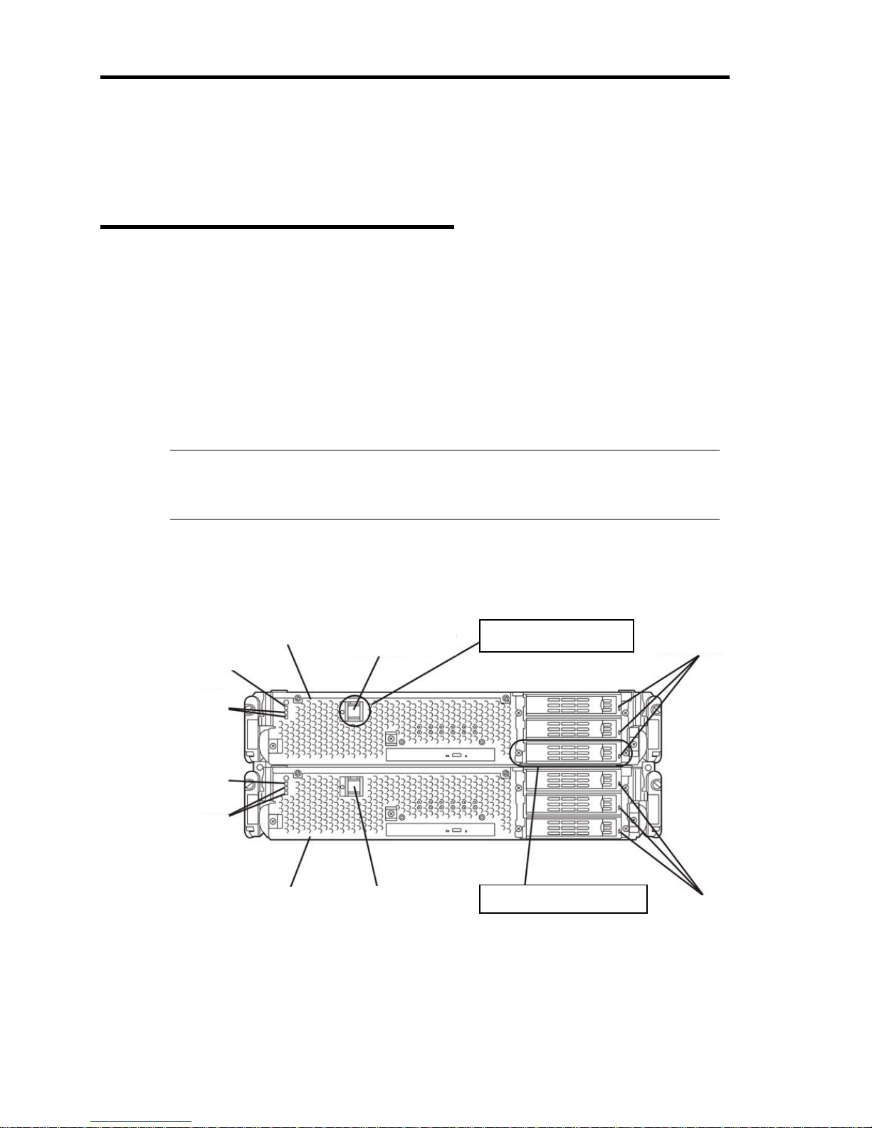
4-8
Step 2: Prepare for Express Setup
Before starting Express Setup, be sure to do the following. You can set up properly only when you
make those preparations.
2-1: Prepare Fault Tolerant Server
series
With the power of Fault Tolerant Server series off, follow the steps below:
1. Prepare Fault Tolerant Server series.
• Mount the modules for both systems.
• Mount only one hard disk to the Slot 1 of the CPU/IO module 0.
• Remove all LAN cables.
• Remove optional SCSI devices such as a tape device from the SCSI connector.
• Remove cables from the connectors attached to the Fibre Channel board.
IMPORTANT:
Mount only one HDD to the designated slot of the designated CPU/IO module. If
multiple HDDs are mounted, the hard disk to install OS cannot be determined.
2. Prepare the installation from the CPU/IO module 0. Mount a HDD to the designated place
when installing the OS.
The location of the parts required for operation and checking are shown below:
CPU/IO module 0
CPU/IO module 0
POWER switch
CPU/IO module 0
Power LED
CPU/IO module 0
Status LED
CPU/IO module 1
Power LED
CPU/IO module 1
Status LED
CPU/IO module 1
Front side of device
CPU/IO module 1
Power switch
CPU/IO module 1
DISK ACCESS LED
CPU/IO module 0
DISK ACCSSS LED
Be sure to keep this
turned on.
Mount only one HDD here
when you install/reinst all O S.
Page 59
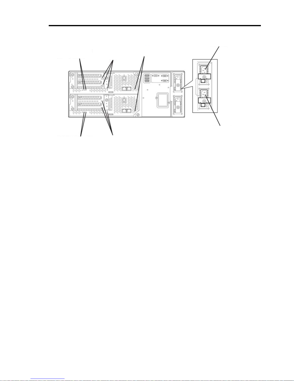
4-9
When the AC power is on (The power cords are plugged into the wall outl et)
(1) Confirm the POWER LED of the CPU/IO module.
z If the POWER LED is illuminated, shut down the OS and unplug the AC
power cord after the POWER LED turns off.
z If the POWER LED is turned off, unplug the AC power cord.
(2) Execute the operation to be taken when AC power supply is turned off.
When the AC power is off (The power cord is not plugged into the outlet)
Connect the power cords to Fault Tolerant Server series in the following order:
(1) Connect the power cord to the AC inlet A connector.
(2) Connect the power cord to the AC inlet B connector.
(3) Make sure that the CPU/IO module status LED is turned off.
Preparation is now completed.
PCI Slot
Status
LED
PCI Slot Status
LED
DUMP (NMI)
Switch
AC Inlet
Connector B
Rear side of device
CPU/IO module 1
Status LED
CPU/IO module 0
Status LED
AC Inlet
Connector A
Page 60

4-10
Step 3: Disable OS Boot Monitoring Function
Check whether the power is ON and make settings for properly performing setup for later on.
This server has a function to monitor the main unit at startup. (Enabled in the configuration at
shipment)
When installing/reinstalling the operating system, this monitoring function needs to be disabled;
otherwise the OS may not install properly. Follow the steps in this section and make proper settings.
IMPORTANT:
If you skip the settings described here, the system will be forcefully restarted while
Windows setup screen is shown and the setup will be unsuccessful. BIOS may repeat
Windows setup in an invalid manner. In this case, you will need to restart the setup
procedures from the beginning.
TIPS:
For details of operations for BIOS Setup Utility and parameters, see the separate volume of
User’s Guide.
Procedure for Changing BIOS settings
1. Turn on the display and the peripheral equipment connected to the Fault Tolerant Server
series.
CHECK:
If the power cords are connected to a power controller like a UPS, make sure that
it is powered on.
2. Detach the front bezel.
Page 61
4-11
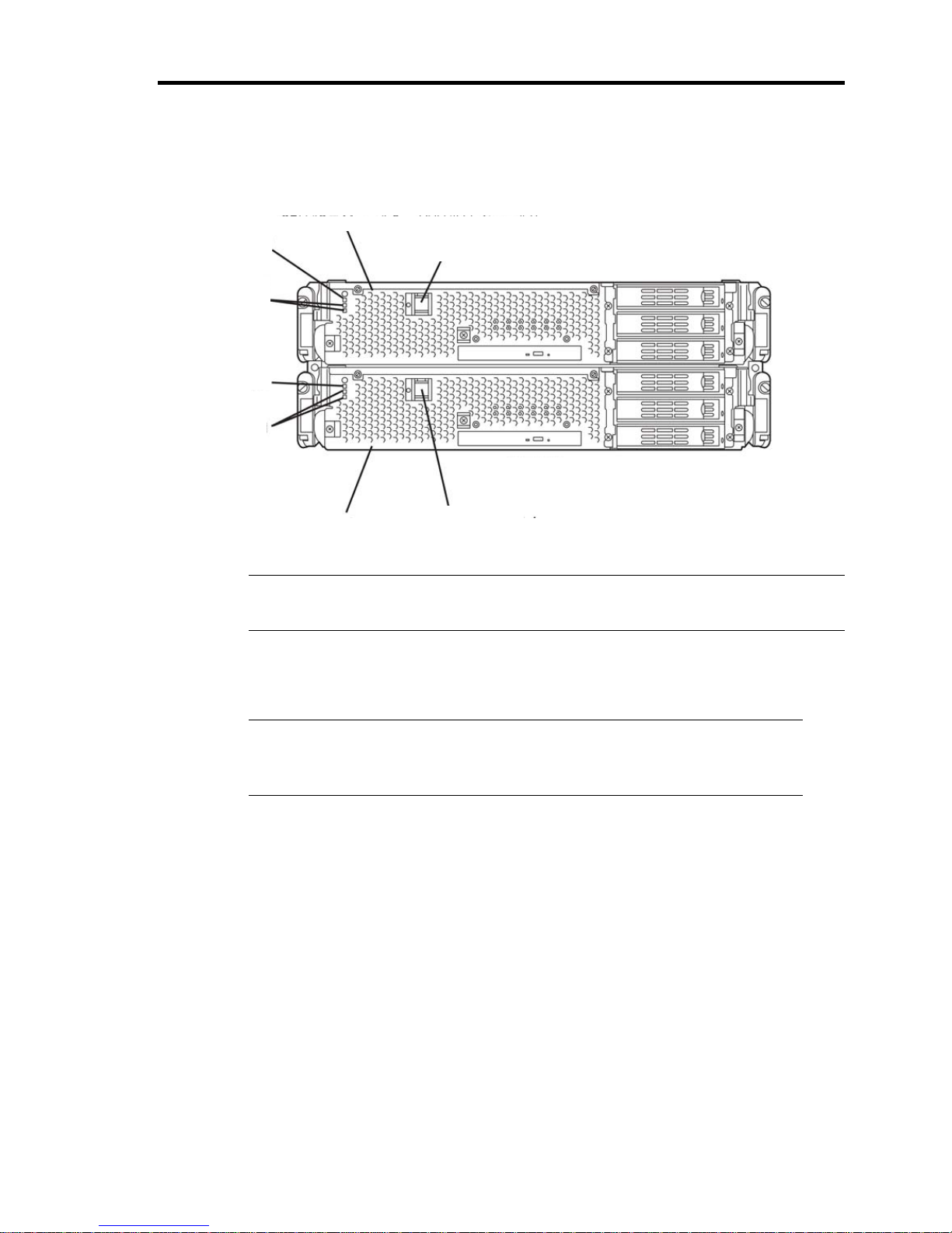
3. Press the POWER switch located on the front side of the server. (You can see LEDs lit on
this side.)
IMPORTANT:
Do not turn off the power before the full screen logo appears.
After a while, the full screen logo will appear on the screen.
While the logo is displayed on the screen, Fault Tolerant Server series performs a power-on
self test (POST) to check itself. For details, see the separate volume of User’s Guide.
CHECK:
If the server finds errors during POST, it will interrupt POST and display the
error message. See the separate volume of User’s Guide.
CPU/IO module 0CPU/IO
module 0
Power LED
CPU/IO module 0
Status LED
CPU/IO module 1
Power LED
CPU/IO module 1
Status LED
CPU/IO module 1
Front side of device
CPU/IO module 1
Power switch
CPU/IO
module 1
Power LED
Page 62
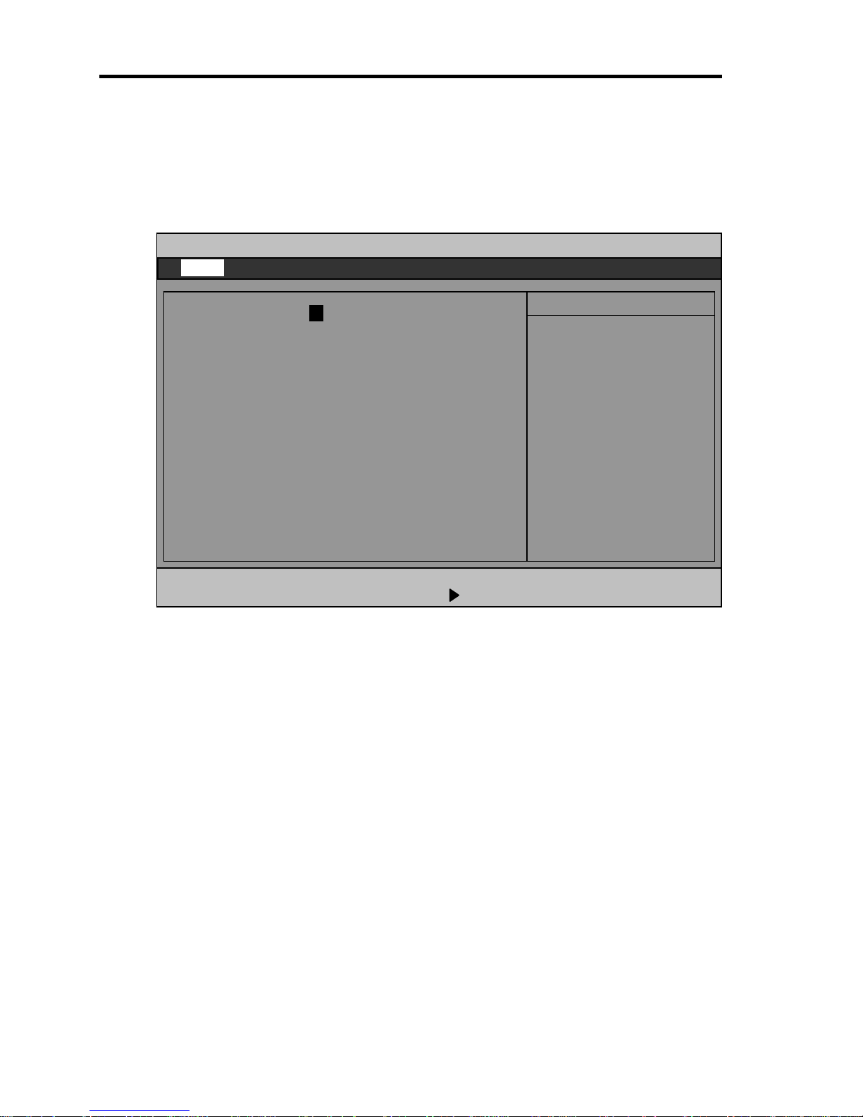
4-12
4. When the message “Press <F2> to enter SETUP” or “Press <F2> to enter SETUP or Press
<F12> to boot from Network” is displayed on the display screen, press F2.
The BIOS Setup Utility “SETUP” starts and the Main menu is displayed on the screen.
Example:
Main Advanced Security Server Boot Exit
ftServer Setup
F1 Help ↑↓ Select Item -/+ Change Values F9 Setup Defaults
Esc Exit ←→ Select Menu Enter Select Sub Menu F10 Save and Exit
System Time: [16:54:28]
System Date: [05/07/2007]
CPU Speed 2.70 GHz
Physical CPUs 1
System Memory 640 KB
Extended Memory 2047 MB
Cache Ram 4096 KB
SATA AHCI Enable [Disabled]
Item Specific Help
<Tab>, <Shift-Tab>, or
<Enter> selects field.
Page 63
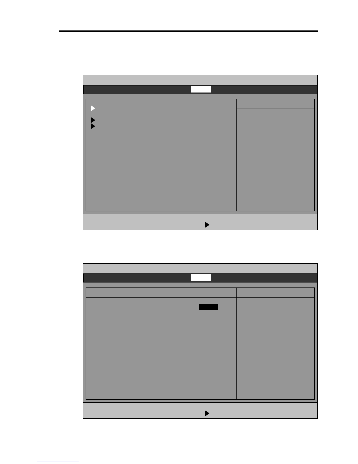
4-13
5. Move the cursor onto “Server” and select “Server.”
The Server menu will be displayed:
6. Move the cursor onto “Monitoring Configuration” and press Enter.
The Monitoring Configuration submenu appears:
Main Advanced Security Server Boot Exit
F1 Help ↑↓ Select Item -/+ Change Values F9 Setup Defaults
Esc Exit ←→ Select Menu Enter Select Sub Menu F10 Save and Exit
Monitoring Configuration Item Specific Help
Disables/enables the
FRB-2 Timer.
FRB-2 Timer [Enabled]
PCI Enumeration Monitoring: [Enabled]
PCI Enumeration Monitoring Timeout: [ 180]
Option ROM Scan Monitoring: [Enabled]
Option ROM Scan Monitoring Timeout: [ 300]
OS Boot Monitoring: [Enabled]
OS Boot Monitoring Timeout: [ 600]
POST Pause Monitoring: [Enabled]
POST Pause Monitoring Time-out [ 180]
Main Advanced Security Server Boot Exit
ftServer Setup
F1 Help ↑↓ Select Item -/+ Change Values F9 Setup Defaults
Esc Exit ←→ Select Menu Enter Select Sub Menu F10 Save and Exit
System Management
Console Redirection
Event Log Configuration
Monitoring Configuration
Post Error Pause: [Enabled]
AC-LINK: [Last State]
Power On Delay Time: [ 0]
Item Specific Help
Additional setup
menu to view
server management
features.
ftServer Setu
p
Page 64
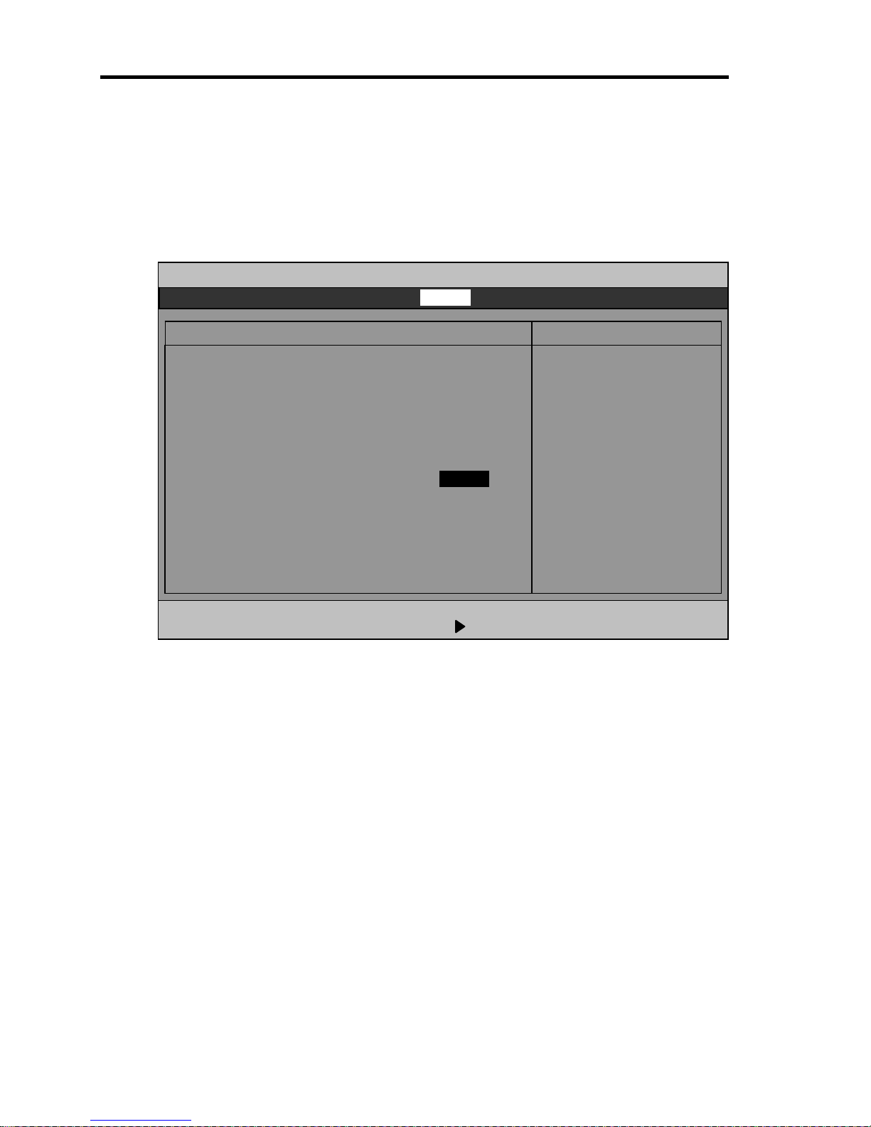
4-14
7. Move the cursor onto “OS Boot Monitoring” and press Enter.
Parameters will be displayed.
8. Among the parameters, choose “Disabled” and press Enter.
The current display of the configuration for OS Boot Monitoring will be changed to
“Disabled.”
Main Advanced Security Server Boot Exit
ftServer Setup
F1 Help ↑↓ Select Item -/+ Change Values F9 Setup Defaults
Esc Exit ←→ Select Menu Enter Select Sub Menu F10 Save and Exit
Monitoring Configuration Item Specific Help
Disables/enables the
FRB-2 Timer.
FRB-2 Timer [Enabled]
PCI Enumeration Monitoring: [Enabled]
PCI Enumeration Monitoring Timeout: [ 180]
Option ROM Scan Monitoring: [Enabled]
Option ROM Scan Monitoring Timeout: [ 300]
OS Boot Monitoring: [Disabled]
OS Boot Monitoring Timeout: [ 600]
POST Pause Monitoring: [Enabled]
POST Pause Monitoring Time-out [ 180]
Page 65
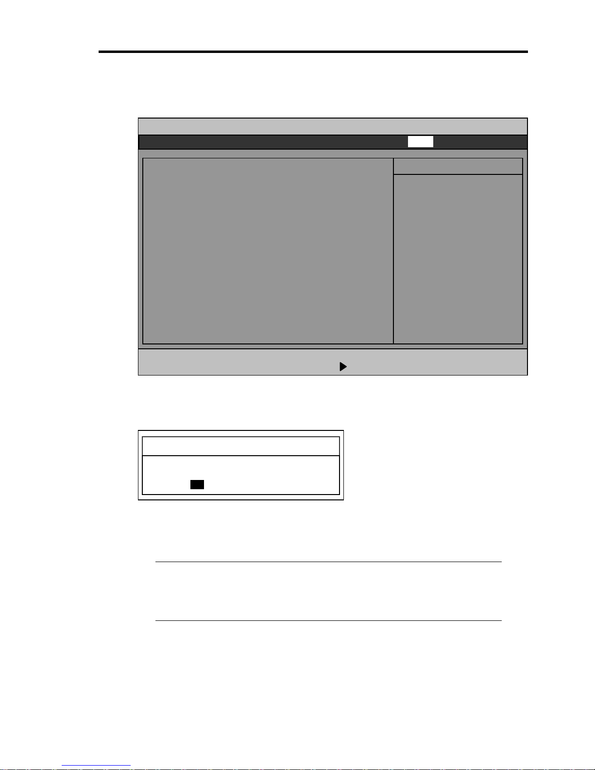
4-15
9. Press the Esc key to go back to the Server menu, and then move the cursor and select
“Exit” to display the Exit menu.
10. Move the cursor onto “Exit Saving Changes” and press Enter.
The confirmation window will appear.
11. Select “Yes” and press Enter.
The configuration data is saved, SETUP terminated, and the system rebooted.
This is the end of steps for switching OS Boot Monitoring function.
TIPS:
After the procedure above is completed, power off this server to prepare for
installation. Then, referring to “Step 4A : Start Express Setup” on the next page
to continue the setup.
Main Advanced Security Server Boot Exit
ftServer Setup
F1 Help ↑↓ Select Item -/+ Change Values F9 Setup Defaults
Esc Exit ←→ Select Menu Enter Select Sub Menu F10 Save and Exit
Exit Saving Changes
Exit Discarding Changes
Load Setup Defaults
Discard Changes
Save Changes
Item Specific Help
Exit System Setup and
save your changes to
CMOS.
Setup Confirmation
Save configuration changes and exit now?
[Yes] [No]
Page 66

4-16
Step 4A : Start Express Setup
Set up with the Express Setup functions of EXPRESSBUILDER.
“Express Setup” is a setup method for Fault Tolerant Server series that allows configuration of
hardware internal parameters and status and installation of OS (Windows Server 2003) and various
utilities in seamless manners by using “EXPRESSBUILDER” DVD which comes with the server.
Use the “Express Setup” to install the OS. It performs complicated setups automatically.
Express Setup edits the information required for the setup, saves it to a floppy disk before the setup,
reads the information one by one at the setup and automatically performs a series of setup processes.
TIPS:
Parameters file is a setup file that stores the information set/selected during Express
Setup. Express Setup executes all the setup process automatically, based on this
information. It is not necessary to sit by the system and check the status during
the setup. If you use the parameters file that has been used last time, you can create
the same setup condition as the previous one.
You can create a parameter file in advance, by using “Parameter File” in
EXPRESSBUILDER.
If you create a configuration diskette in advance, you can skip the options that need
to be entered or selected during Express Setup. (You can create or modify the setup
information in the configuration diskette, during Express Setup.) If any computer
that is running on Windows XP/Vista/Windows Server 2003 is available, it is
recommended to edit the setup information with Configuration Diskette Creator in
advance.
This device does not include the floppy disk (FD) drive by standard. Prepare an
optional floppy drive when you create and use parameters file.
Page 67
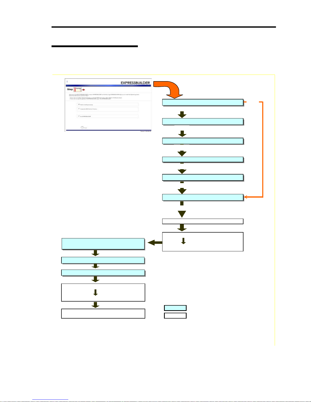
4-17
Flow of Setup Procedures
The following flow chart illustrates the setup procedures for Express Setup.
Loading parameters (Step 2)
Select the operating system (Step 3)
RAID configuration (Step 4)
Windows Confirm Setting / Input (Step 5 to 10)
Save parameters (Step 11)
Start Express Setup (Step 12)
Create the OS partition / format
Remove the Floppy Disk and CD/DVD-ROM from
the drive
Copying Windows driver
Copying Selected Application
Insert Windows CD-ROM
Agree Software License Agreemen
t
Install OS Automatically
Log on Automatically
The installation is completed
Next
N
ext
N
ext
N
ext
N
ext
Perform
Skip
: Process that needs to input or select
: Process that proceeds
automatically
Page 68
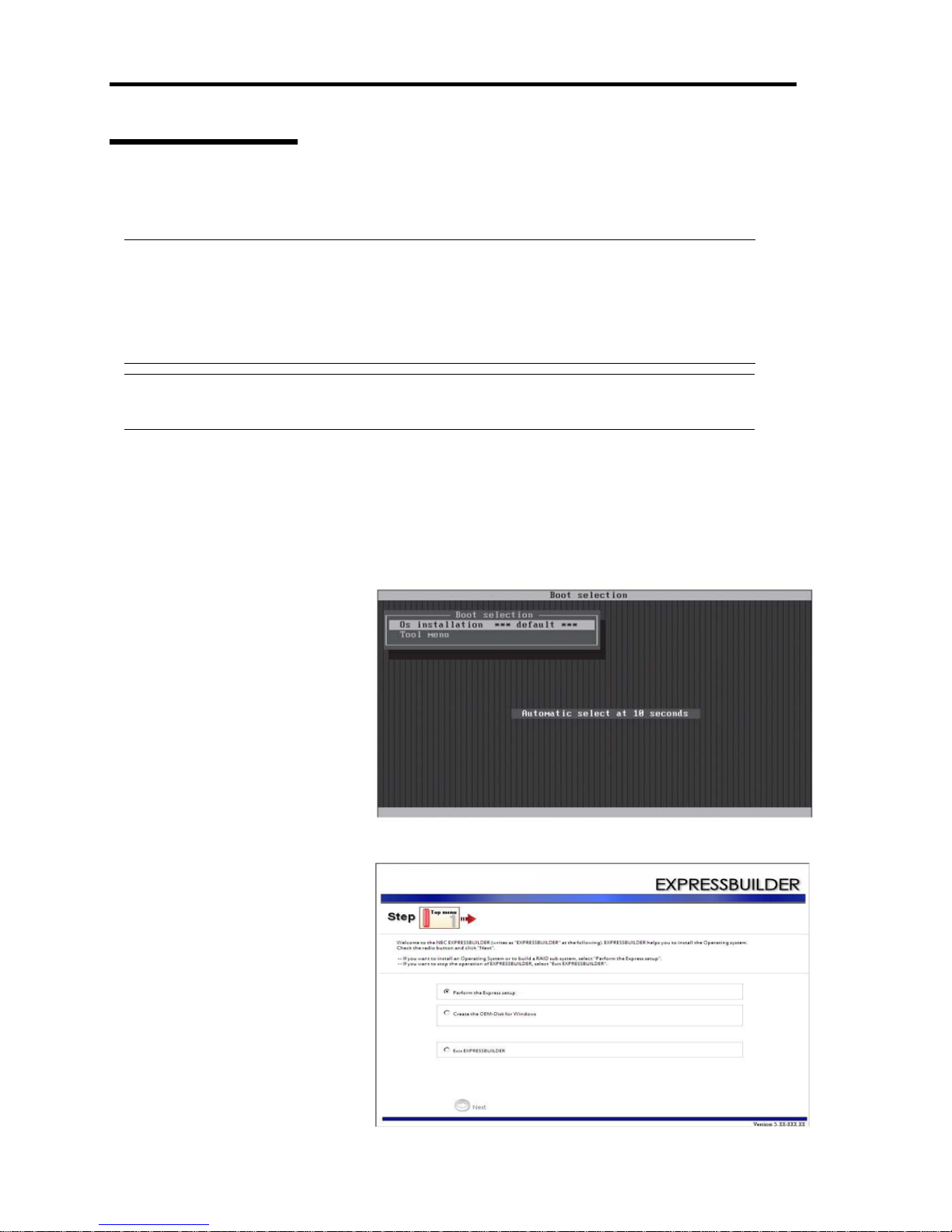
4-18
Setup Procedures
Express Setup precedes the setup by selecting or inputting several parameters on the wizard.
You can also save the parameters to a floppy disk as a parameters file.
CHECK:
To execute Express Setup with a parameter file, one empty 1.44MB formatted floppy disk
is required. Prepare an empty floppy disk in advance.
When you reinstall OS, you can skip entering the parameter in the Wizard form, by reading
the parameter file that has been saved.
IMPORTANT:
In case of changing the system configuration, update the system (page 6-8).
1. Turn the power of peripheral device on, and then turn on the server.
2. Insert the EXPRESSBUILDER DVD into the optical disk drive of the server.
3. Press the RESET switch or press Ctrl, Alt, and Delete to reboot from the
EXPRESSBUILDER. (You may also turn off and then on again to reboot
the server.)
The system will boot from
the DVD-ROM and
EXPRESSBUILDER starts.
Select “OS installation ***
default ***” from the boot
selection menu.
(If you do not hit any key,
“OS installation” is selected
automatically.)
The Top menu will appear.
4. Select [Perform the Express
setup] from the Top Menu,
click [Next].
Page 69
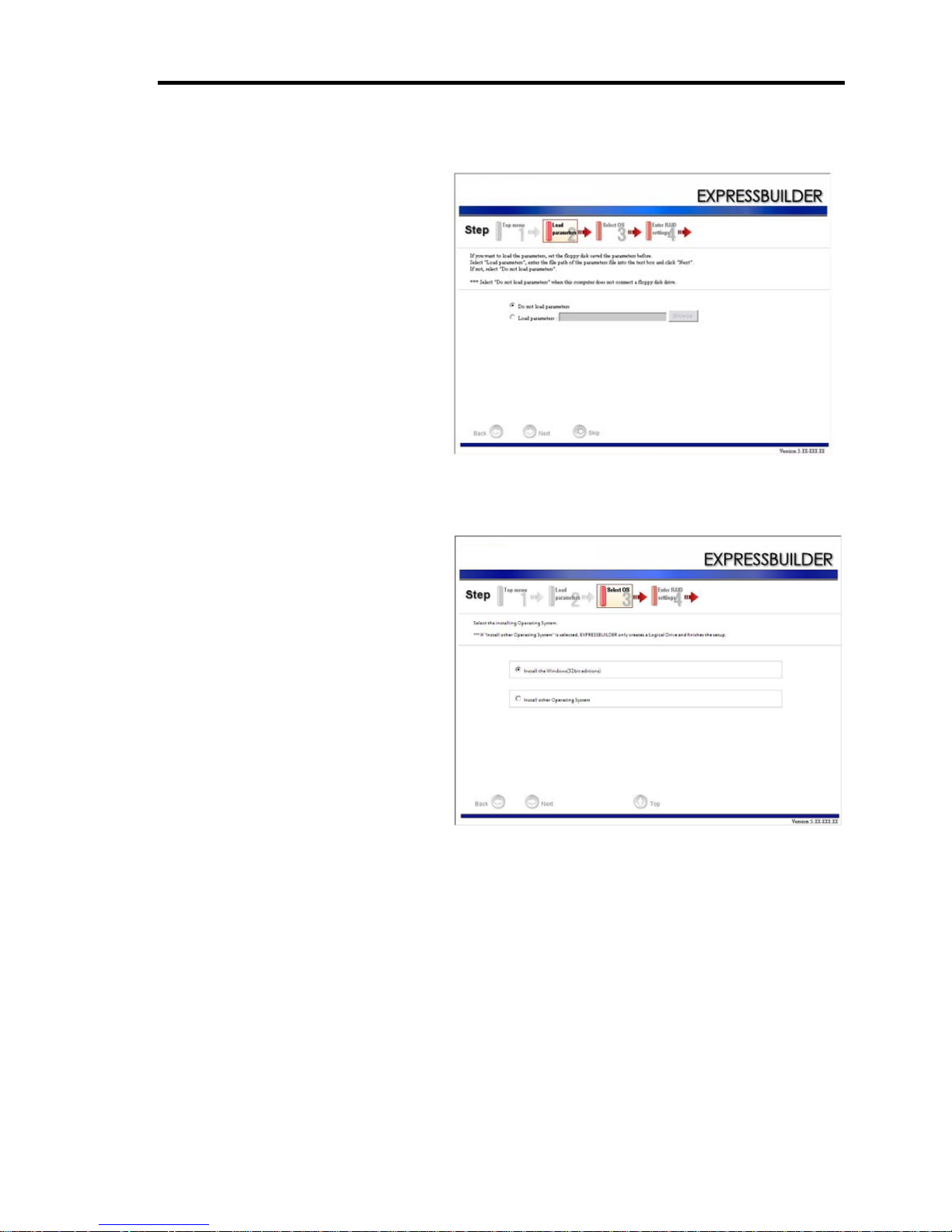
4-19
5. [Load parameters] steps are displayed.
[Load parameters]
(1) Select [Do not load
parameters].
(2) Click [Next].
NOTE: If a floppy disk drive is
not connected, select this item.
[When you load parameters]
(1) Insert the floppy disk
containing the parameters file.
(2) Select [Load parameters];
enter the file path of the
parameters file into the text
box.
(3) Click [Next].
6. Select the installing Operating
System.
Select [Install Windows (32-bit
editions)] from the menu, click
[Next].
Page 70
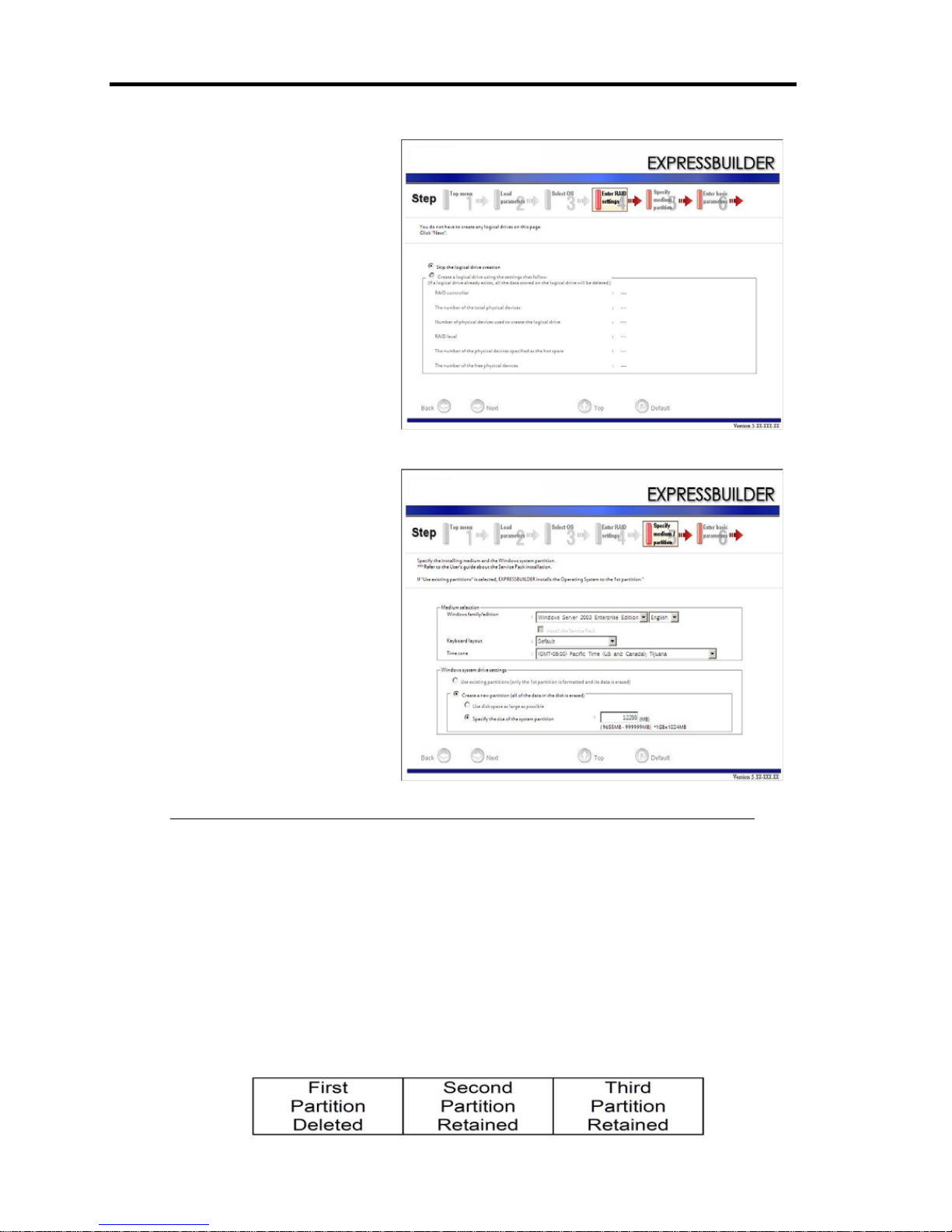
4-20
7. Enter the setting of a logical
drive.
[Enter RAID settings] steps are
displayed. Retain the default
value, and click [Next].
8. Specify the installing medium
and the Windows system
partition.
[Specify medium / Partition]
steps are displayed. Confirm
the parameters, modify if
necessary, and click [Next].
IMPORTANT:
About partition size
1. Specify the partition size larger than required minimum size for OS installation.
2. Do not specify larger partition size than the capacity of connected hard disk drive.
If you select “Create a new partition” at “Windows system drive settings,” the
contents of the hard disk will be all deleted.
If “Use existing partitions” is selected, EXPRESSBUJILDER installs the
Operating System to the first partition (first partition is deleted). The data in the
other partition is kept if the system has two or more partitions (see the figure
below).
Page 71
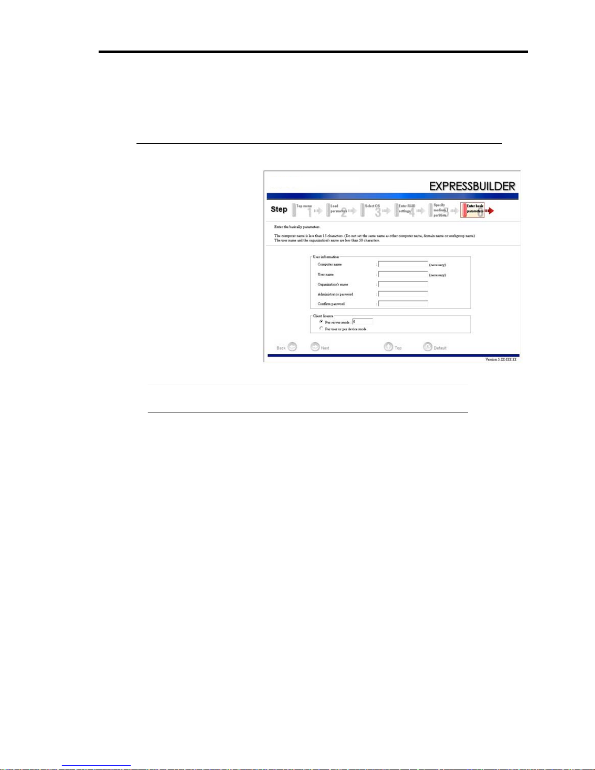
4-21
You cannot reinstall the system with the existing partition that is upgraded to
Dynamic Disk remained. Do not select “Use existing partitions” at “Windows
system drive settings.”
9. Enter the user information
and client license mode.
[Enter basic parameters]
steps are displayed.
Confirm the parameters,
modify if necessary, and
then click [Next].
NOTE: Even if you do not input value into “Administrator password,”
“Confirm password,” “??????” is displayed.
Page 72
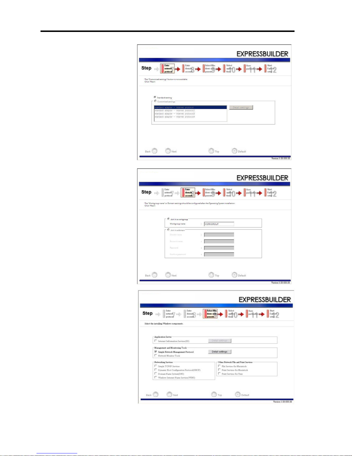
4-22
10. Enter the setting of
the network protocol.
[Enter Network Protocol]
steps are displayed.
Retain the default value, and
click [Next].
11. Enter the domain or
workgroup name to be used.
[Enter domain account]
steps are displayed.
Retain the default value, and
click [Next].
12. Select the installing
components.
[Select Windows
components]
steps are displayed.
Retain the default value, and
click [Next].
Page 73
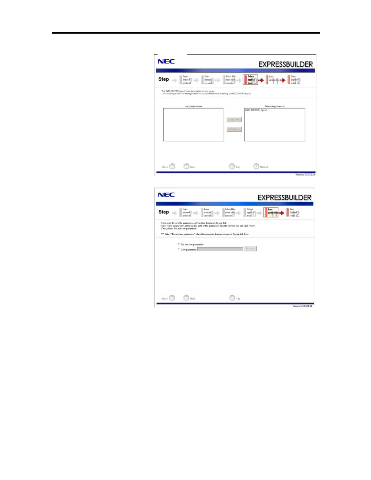
Windows Setup 4-23
13. Select the installing applications.
[Select applications]
steps are displayed.
Retain the default value, and
click [Next].
14. Save the parameters.
[Save parameters]
steps are displayed.
If you want to save
the parameters,
set free formatted floppy
disk.
Select [Save parameters],
enter the file path of the
parameters files into the
textbox and click [Next].
If not, select
[Do not save Parameters].
Page 74
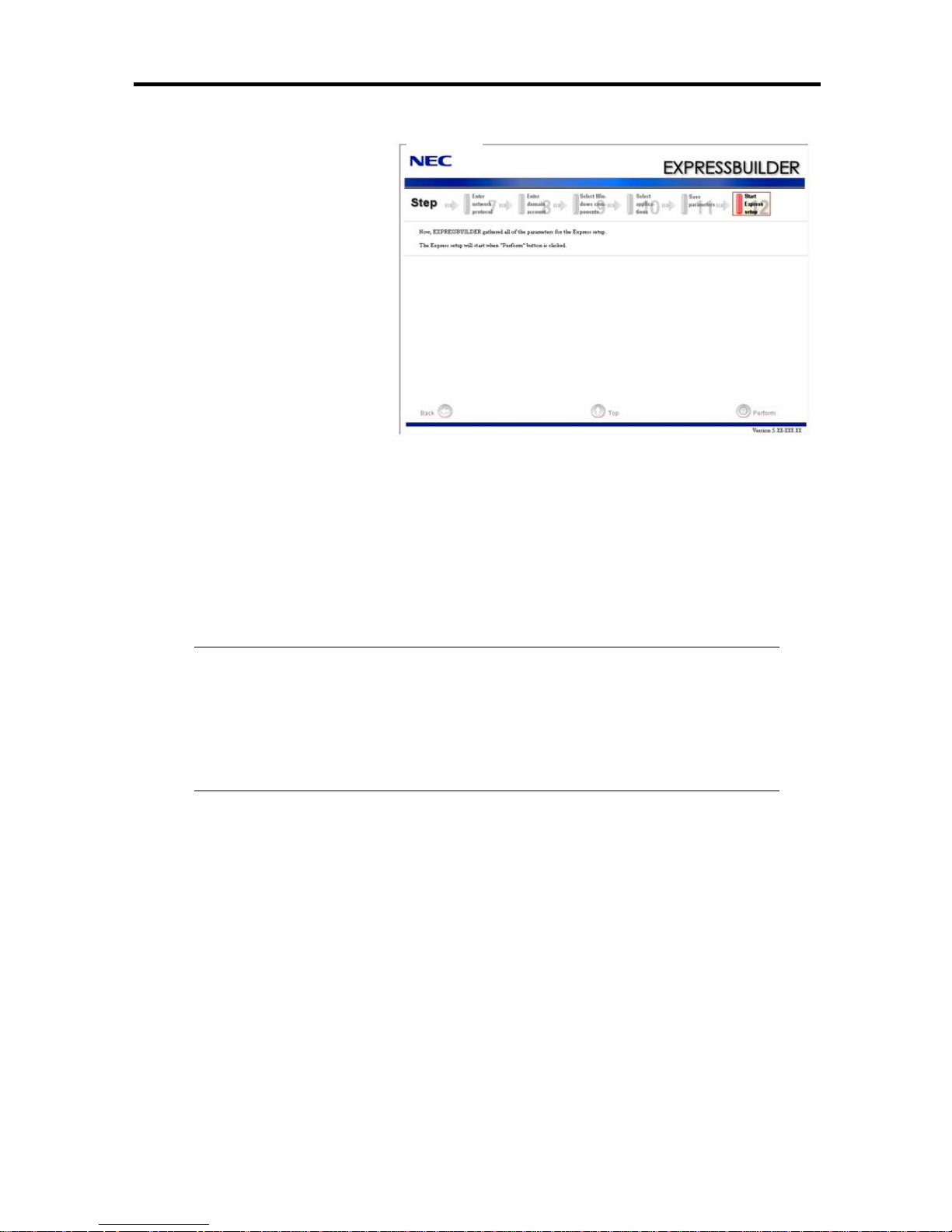
4-24
15. The Express Setup will start
when you click [Perform] in
[Start Express setup] step.
16. Remove EXPRESSBUILDER DVD from the optical disk drive according to the message.
If you proceed the setup y using setup parameter file, remove the floppy disk from the floppy
disk drive.
Insert Windows Server 2003 CD-ROM into the optical disk drive.
[Agree Software License Agreement] screen appears.
17. Read the contents carefully and click [Yes] if you do agree. If do not agree, click [No].
NOTES:
If you do not agree to this agreement, the setup terminates and Windows Server
2003 will not be installed.
If “NetWare Gateway (and Client) Service” is specified to install, the window to
specify the details of “NetWare Gateway (and Client) Service” pops up on the
first logon. Specify the appropriate value.
Windows Server 2003 and selected applications will be installed automatically and rebooted
several times. After rebooting, it logs on to the system automatically.
18. Insert Microsoft Windows Server 2003 R2 Standard Edition DISK 2 into the optical disk
drive after the OS installation.
Hereafter, proceed operations according to the message.
When the installation has finished, remove Microsoft Windows Server 2003 R2 Standard Edition
DISC 2 from the optical disk drive, and restart the system.
Now the Setup using Express Setup has completed.
Step 4B: Manual Setup
Follow the procedures below to create “OEM-Disk” before starting the OS install.
Page 75

4-25
Preparing to Install
Windows Server 2003 x64 Editions
You can create a Windows Server2003 x64 Edition OEM-Disk for EXPRESSBUILDER by
following two procedures.
Create from EXPRESSBUILDER
Select this procedure when the Fault Tolerant Server series is the only computer for creating
Windows Server2003 x64 Edition OEM-Disk for EXPRESSBUILDER. If Windows Server 2003
x64 Editions operates on the Fault Tolerant Server, you can also select [Create from the menu start
by auto-run] described later.
The procedure is as follows:
1. Prepare one 3.5-inch floppy disk.
2. Insert the [EXPRESSBUILDER] DVD into the optical disc drive.
3. Reset (Press <Ctrl> + <Alt> +<Del>) or power off to reboot the server series.
System launches from the DVD-ROM, and EXPRESSBUILDER starts.
4. Select [Create the OEM-Disk for Windows] from the [Step 1, Top menu], then click [Next].
5. Select [Create Windows Server 2003 x64 Edition OEM-Disk for EXPRESSBUILDER] from
the [Create Windows OEM-Disk], then click [Perform].
6. Follow the instruction on the screen and set the floppy disk into the floppy disk drive.
[Windows Server 2003 x64 Editions OEM-Disk for EXPRESSBUILDER] is created.
Protect the disk from overwrite and label as [Windows Server 2003 x64 Edition OEM-Disk
for EXPRESSBUILDER]. Store this OEM disk in a safe place.
Create from the menu start by auto run
Menu starts automatically by the auto run function when you load the DVD into an optical disc
drive that is mounted on a computer running an operating system Windows 2000 + Internet Explorer
6.0, Windows XP, Windows Vista or Windows Server 2003. From this menu, you can create
[Windows Server2003 x64 Edition OEM-Disk for EXPRESSBUILDER].
Page 76

4-26
The procedure is as follows:
1. Prepare one 3.5-inch floppy disk.
2. Start the operating system.
3. Insert the [EXPRESSBUILDER] DVD into the Optical disk drive. The menu launches.
4. Click [Create drive disk (for Windows)], and select [OEM-Disk for Widows Server 2003 x64
Edition].
NOTE:
This operation is also possible on the menu that appears by right click.
5. Follow the instruction on the screen and set the floppy disk into the floppy disk drive.
[Windows Server 2003 x64 Edition OEM-Disk for EXPRESSBUILDER]. Store this OEM
disk in a safe place.
Page 77
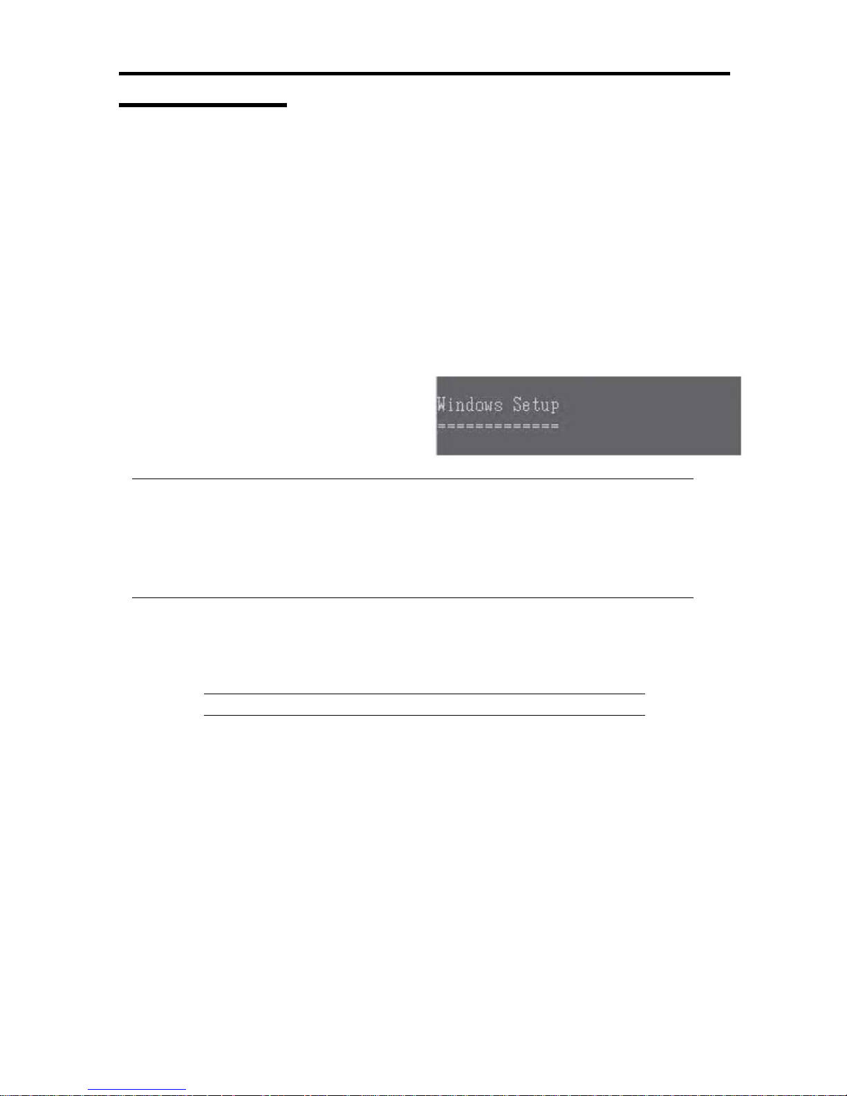
4-27
Installing Windows
Windows Server 2003 x64 Editions Installation
Follow the procedure below to install.
1. Power on the system.
2. Load the backup CD-ROM DISK 1 or the Windows Serv er 20 0 3 x6 4 Ed i tion DISK 1 into
the optical disk drive.
3. After loading the backup CD-ROM DISC 1 or the Windows Server 2003 R2 x64 Edition
DISC 1 into the optical disc drive, reset (Press <Ctrl> + <Alt> +<Del>), or power off to
reboot the server series.
System launches from the CD-ROM, and
EXPRESSBUILDER starts.
IMPORTANT:
When a bootable OS is already installed on the HDD, press <Enter> key while [Press any
key to boot from CD…] is appearing on the top of the screen. You do not need to operate
this if no bootable OS is installed.
If the Windows Setup screen does not appear after this operation, it means <Enter> key was
not pressed properly. Power on to restart the system and start from the beginning.
4. Press <F6> key while either of the following messages appears on the screen.
On the top of the screen: [Setup is inspecting your computer’s configuration…]
On the bottom of the screen: [Press F6 if you need to install a third party SCSI or
RAID driver]
TIPS: After pressing <F6> key, no change appears on the screen.
Page 78
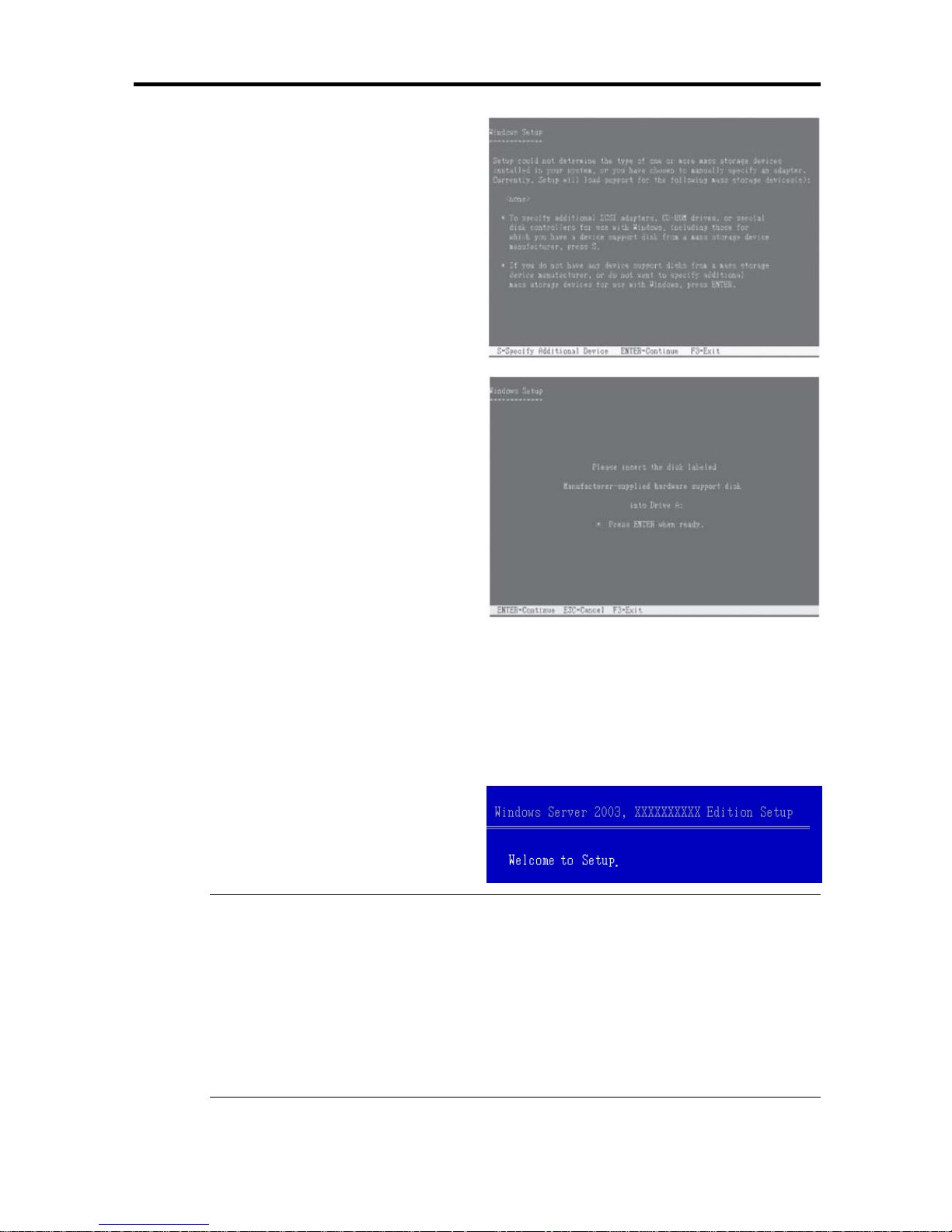
4-28
5. Press <S> key when the right message
appears.
The right message appears.
6. Set Windows Server 2003 x64 Edition OEM-Disk for EXPRESSBUILDER floppy disk into
the floppy disk drive, then press <Enter>.
SCSI adapter list appears.
7. Select [Stratus Virtual Disk Driver], then press <Enter>.
Go back to the step 5 screen and press <Enter>.
8. Select [Stratus Embedded SAS Adapter], then press <Enter>
9. Press <Enter> and start Windows setup
when the right message appears.
IMPORTANT:
– On the process of the setup, the request to configure the partition size of
Windows Server 2003 x64 Editions installation appears on the screen.
– When you try to install Windows Server 2003 x64 Editions on a disk that has larger
partition than 2,097,152MB (2TB), the partition size should be 2,097,152MB and
less.
Page 79

4-29
– When there are multiple logical drives, select a partition that you would like to
install the OS after the next message appears.
– You cannot change drive letters for the system volume or the boot volume after
completing the setup. Make sure the drive letter is allocated to proper drive on
this screen, and then proceed the setup.
After completing the setup, the drive letters may not be the same as before the
setup. If you would like to change the drive letters, follow the procedure [How to
change drive letters] described later.
TIPS:
After copying the files, the system automatically reboots. You do not
have to eject the floppy disk and the CD-ROM. When you do not eject
the floppy disk, do not eject the CD-ROM either.
Follow the instructions on the screen to continue the setup. Refer to
[Fist Step Guide] for details.
10. After installing Windows Server 2003 x64 Editions, the system automatically reboots.
11. After logging on the system, [Windows Setup] screen appears.
IMPORTANT:
– [Windows Setup] screen may not appear; however, make sure to install
Microsoft Windows Server 2003 R2 x64 Editions DISK 2.
– After applying [System Update], you can install Microsoft Windows Server
2003 x64 Edition DISK 2. Make sure to install Microsoft Windows Server 2003
R2 x64 Edition. [Windows Setup] screen does not appear this time.
12. Load the Microsoft Windows Server 2003 R2 x64 Edition DISK 2 into the Optical disk drive.
Check the setting, then click [OK].
13. After the installation, eject the Microsoft Windows Server 2003 R2 x64 Edition DISK 2 from
the Optical disk drive, then reboot the system.
14. Refer to the “System Update” to apply the update.
15. Install software
– ft Server Control software
– NEC ESMPRO/ServerAgent
The following list shows the existing partitions and unpartitioned space on
this computer.
Use the UP and DOWN ARROW ke
y
s to select an item in the list.
Page 80
4-30
Changing Drive Letters
You can change the drive letters with the following procedure:
NOTE:
The following procedure does not change the drive letters for the system volume or
the boot volume.
1. Go to the start menu, right click [My Computer], select [Manage] and then launch
[Computer Management].
2. Select [Disk Management] in the left window.
3. Select and right-click a volume that you want to change the drive letter,
then select [Change Drive Letter and Path for…].
4. Click [Change].
5. Click [Change Drive Letter or Path], then select a letter for the drive.
6. Click [OK].
7. Click [Yes] after confirming the following message.
8. Exit [Computer Management].
Changing the drive letter of a volume might cause programs to no longer run.
Are you sure you want to change this drive letter?
Page 81

4-31
Step 5: Windows Server 2003 Service Pack Installation
Installing Windows Server 2003 Service Pack
A Service Pack for Windows Server 2003 x64 Edition and Windows Server 2003 is not applied to
the system immediately after Windows install and re-install.
Refer to “Applying Windows Service Pack” on page 5-14, and apply Windows Server 2003 x64
Edition and Windows Server 2003 Service Pack.
IMPORTANT:
The Service Pack 2 for Windows Server 2003 x64 Edition or for Windows Server 2003
must be installed on the Fault Tolerant Server server.
There is no Hot Fix when this User’s Guide is issued. Contact your sales representative
for the latest Service pack or the Hot Fix.
Step 6: Set Duplex LAN Configuration
The Fault Tolerant Server series builds a duplex LAN configuration by using “Stratus emb-EB
2-Port Gigabit Adapter” mounted as standard on the CPU/IO module and extended PCI slot “NEC
MT Gigabit Adapter,” “NEC MF Gigabit Adapter,” and “Stratus U575 Dual Port Copper Gigabit
Adapter.”
Overview
The duplex LAN configuration is of three types as described below:
Adapter Fault Tolerance (AFT)
Adapter Fault Tolerance (AFT) is a feature that places more than one LAN controller on the
same LAN (same segment), and automatically switches the process of the primary controller to
the backup controller when any trouble occurred on the primary.
Adaptive Load Balancing (ALB)
Adaptive Load Balancing (ALB) is a feature that connects more than one LAN controller to
the same hub and enhances the throughput by operating packet transmission from the server.
Receive Load Balancing (RLB) is enabled by default. Disable RLB. When RLB is enabled,
the network duplex configuration may fail.
Switch Fault Tolerance (SFT)
Switch Fault Tolerance is a feature that provides the network availability as the failover target
(standby) adapter takes over MAC address and L3 address by connecting each two adapters to
each two switches when a problem occurs on the adapter, cable or connecting target. One is
assigned to the primary adapter and the other is to the standby. The primary adapter
communicates on the network.
Page 82

4-32
Regarding the path redundancy, you need to construct the environment by using the spanning
tree not only on the server side but also on the switch side.
You need to set the priority of the switch so that the path through the primary adapter is
available even when a switch on the path is broken and the path information is updated.
The other modes, “Static Link Aggregation” and “IEEE 802.3ad Link Aggregation” do not
contribute to an enhancement of the fault tolerance. When a fault occurs, the communication
performed on the controller with the fault will be lost; the backup controller does not take it
over.
Page 83
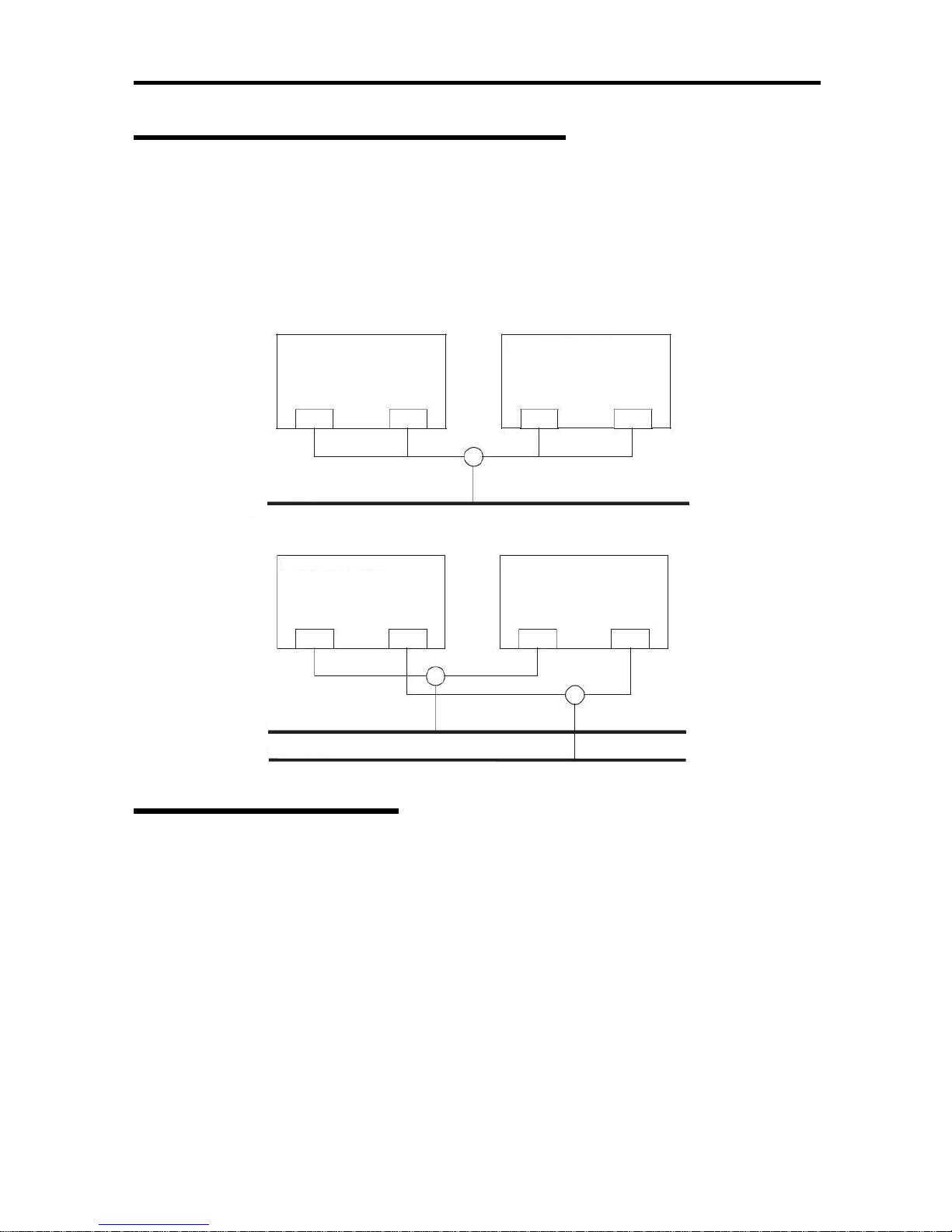
4-33
Fault Tolerant Server Series Duplication
Rule
Be sure to set the duplex configuration in the server.
Also, when you set the duplex configuration, be sure to use one CPU/IO module 0 adapter and one
CPU/IO module 1 adapter.
e.g.1) Set the duplex configuration with the improved endurance using all the adapters.
e.g.2) Set the duplex configuration for more than one LAN connection
Duplex Configuration
Setup
The following describes the procedure to set duplex LAN configuration.
The procedure to set the duplex LAN configuration of the example 1 in “Fault Tolerant Server
Series Duplication Rule” above is explained.
To set the duplex LAN configuration, log on as “Administrator” or a member of the group
“Administrators.”
1. Start Device Manager.
CPU/IO module 0 CPU/IO module 1
Network
CPU/IO module 0 CPU/IO module 1
Network 1
Network 2
Page 84
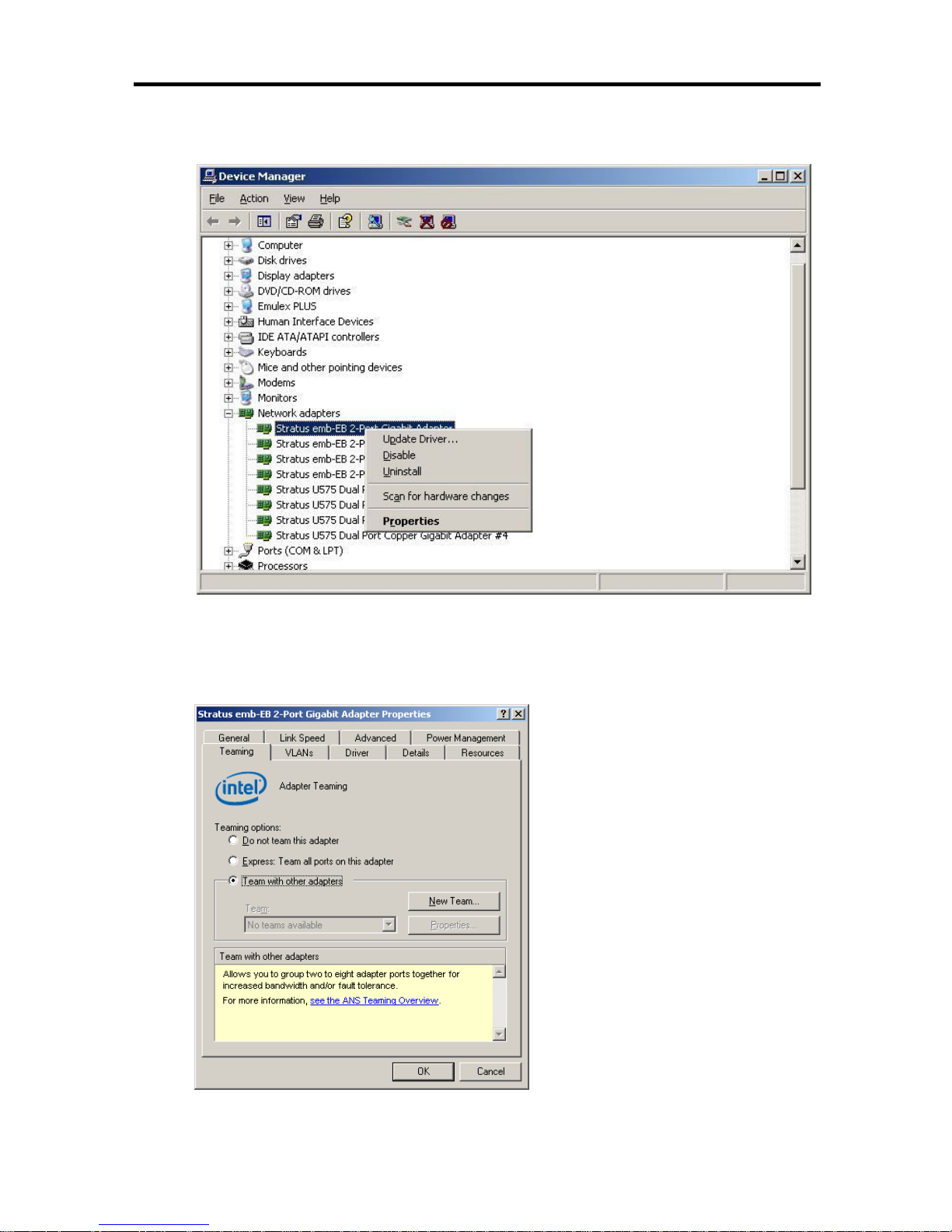
4-34
2. Select one target network adapter, right-click on it and select [Properties] from the
displayed menu to display the Properties window.
3. Select the [Teaming] tab in the Properties window. Check the radio button of [Team with
other adapters] and click [New Team…].
Page 85
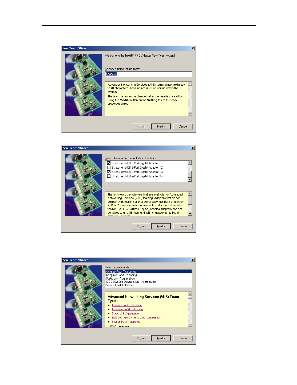
4-35
4. Enter the team name, and click [Next >].
5. Select the check boxes of the adapters you want to include to the team, and click [Next>].
6. Select “Adapter Fault Tolerance” or “Adaptive Load Balancing” or “Switch Fault
Tolerance” as a team mode. (Usually select “Adapter Fault Tolerance.”)
Click [Next >].
Page 86
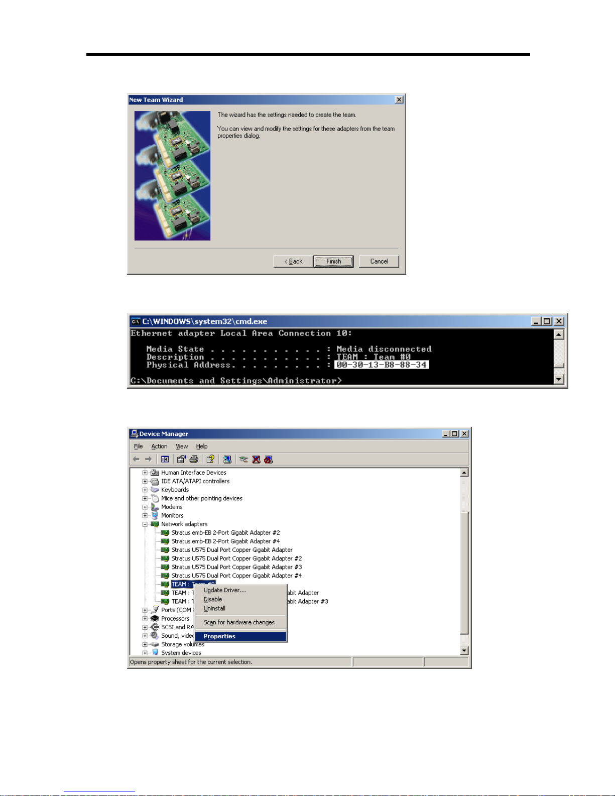
4-36
7. Click [Finish].
8. Start a command prompt, and confirm the physical MAC address of the team adapter with
ipconfig /all.
9. Select the team adapter that has been set, right-click on it and select [Properties] from the
menu displayed to display the Properties window.
Page 87
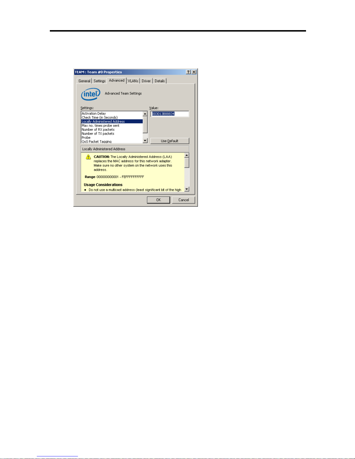
4-37
10. Select the [Advanced] tab in the Properties window. Select [Locally Administered Address]
from the [Settings] list box, and enter the MAC address of team adapter that you have
checked in the [Value:] text box, and click [OK].
11. Set the probe setting disabled when a team of two adapters is configured.
Select the [Advanced] tab in the Properties window. Select [Probe] from the [Settings] list
box, and click [Disabled] from the [Value:] dropdown list.
Page 88
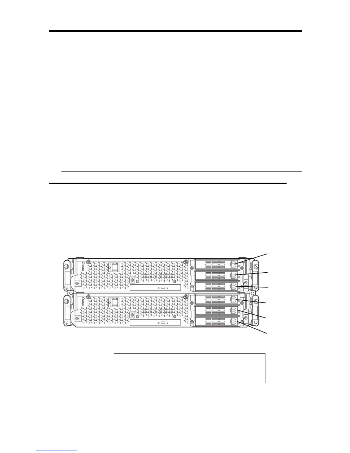
4-38
Step 7: Set Dual Disk Configuration
Fault Tolerant Server series secures data by setting dual disk configuration using “RDR (Rapid Disk
Resync) function.” Be sure to make dual disk settings by referring to the procedure.
IMPORTANT:
• Set dual disk configuration by the RDR (Rapid Disk Resync) function. If you want to use
other disk management tool (e.g. VERITAS Storage Foundation), install it after “Step 13:
Make Settings for Failure Management.” If you perform this operation with a tool other
than the RDR (Rapid Disk Resync), a mirror synchronization gap may occur when the
system is rebooted.
• CPU/IO module has a processor function part and IO function part, and monitors and
manages each part. The IO function part is referred to as PCI module in this section.
• HDDs mounted to built-in slots need to be duplexed. Refer to “Setting Dual Disk
Configuration by RDR (Rapid Disk Resync) function” and duplex the HDDs in each slot.
Setting Dual Disk Configuration by RDR (Rapid Disk Resync)
function
This device sets dual configuration for each disk by the RDR function of the ft server control
software.
By setting RDR, as the following figure and table show, dual configuration is set between the disks
of the corresponding slots, and these disks are recognized as one virtual disk by Windows (such as
Disk Management and Device Manager).
Corresponding slot
PCI module 0 Slot 1 Ù PCI module 1 Slot 1
PCI module 0 Slot 2 Ù PCI module 1 Slot 2
PCI module 0 Slot 3 Ù PCI module 1 Slot 3
* In the table above, PCI module names correspond as follows:
PCI module (for CPU/IO module 0) - PCI module 0
PCI module (for CPU/IO module 1) - PCI module 1
Slot 3
Slot 2
Slot 3
Slot 2
Slot 1
Slot 1
HDD slots that correspond to mirroring
Page 89
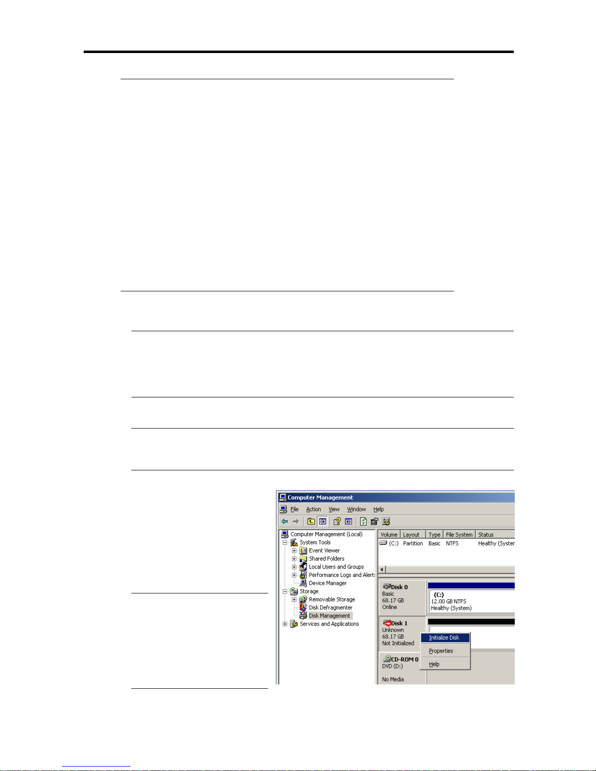
4-39
IMPORTANT:
To perform this procedure, you need to log on as an administrator or a
member of administrator group.
RDR can only be set on the basic disk inserted into the built-in slot of
Fault Tolerant Server series. It cannot be set on the dynamic disk.
For the disk on which RDR is set, use the products with the same serial
number.
Be sure to configure the RDR settings in the same way not only when
the OS is installed but also when the disk is added to the PCI module.
Create partitions only after the duplication of the hard disk drives are
configured.
Follow the steps below to configure the dual disk configuration.
IMPORTANT:
The following describes the dual disk configuration of the slot 1.
If the HDD is mounted to the slot 2 or the slot 3, follow the procedure below to
configure the dual disk configuration likewise.
1. Insert a new HDD into an internal HDD slot.
IMPORTANT:
If the HDD is already mounted, this procejure is not required. Proceed to Step 2.
2. Start [Management Tool] by going
to [Start] – [Control Panel], and
select [Disk management on the
left tree. If the disk you want to
duplex is shown as “Not
Initilized,” right click on the disk
to initialize.
TIPS:
A popup window is displayed
when you inserted or
initialized the disk; however,
you do not need to restart the
system. Select [No] to exit the
popup window.
Page 90
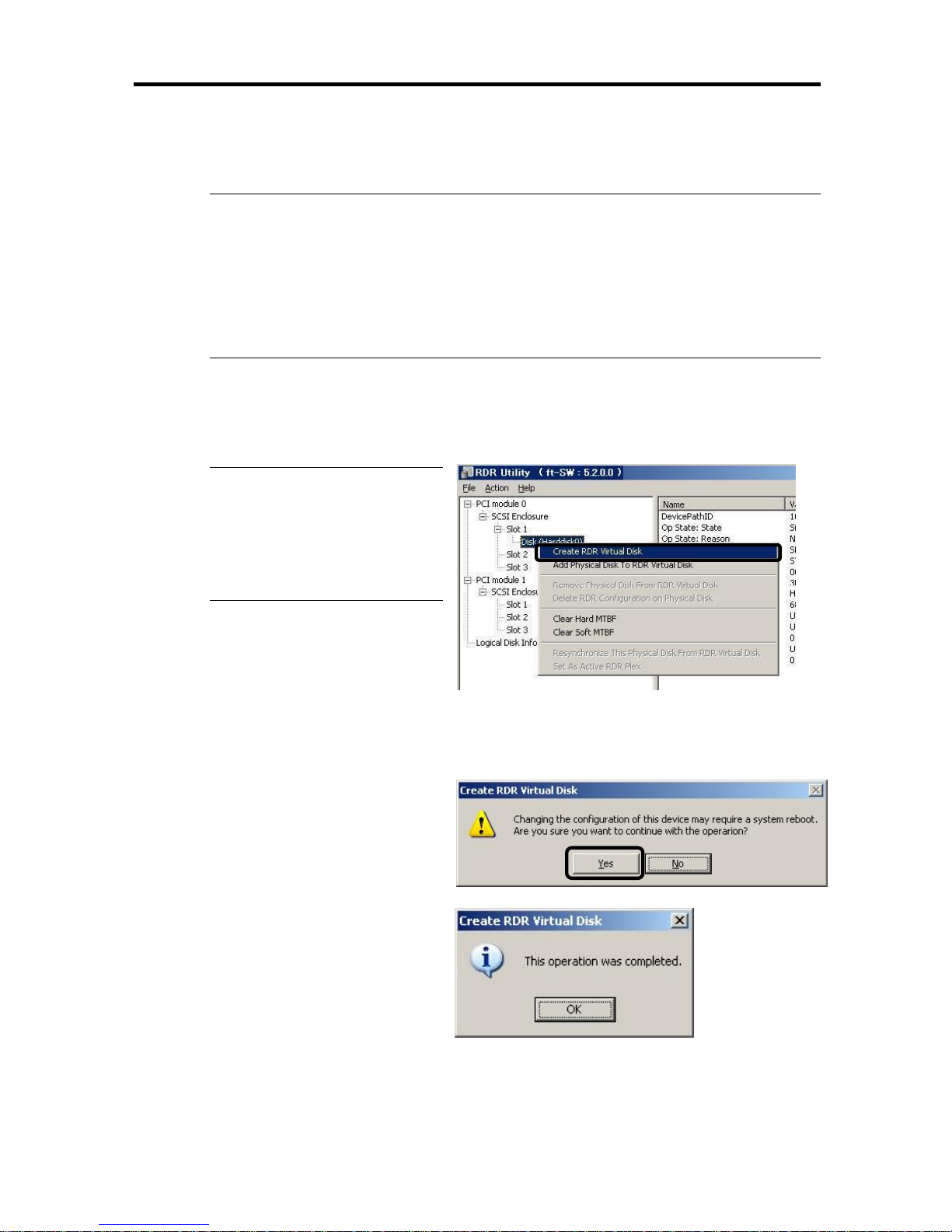
4-40
3. Start RDR Utility by goint to [Start] -
[All Programs] -[RDR] [RDR Utility].
IMPORTANT:
If the [Disk Condition] of the OS-installed disk(the slot 1 of the PCI module 0) says
“Boot/Configured/Active/Imported,” you do not need to take the procedure 4 to 6.
Proceed to the procedure 7.
If the [Disk Condition] is other than “Boot/Configured/Active/Imported,” proceed to the
procedure 4. To view [Disk Condition], go to the left pane of the RDR Utility, click the
OS-installed disk, and see the display on the right pane.
4. Right-click the disk (Slot 1 of PCI module 0) on which the system is installed on the left
pane of the [RDR Utility] window, and click [Create RDR Virtual Disk].
TIPS:
Depending on the disk status, it
takes time to set RDR, and RDR
Utility may be stopped for a few
minutes. This is not an error. Just
wait for a while.
5. Click [Yes].
6. Click [OK].
Page 91
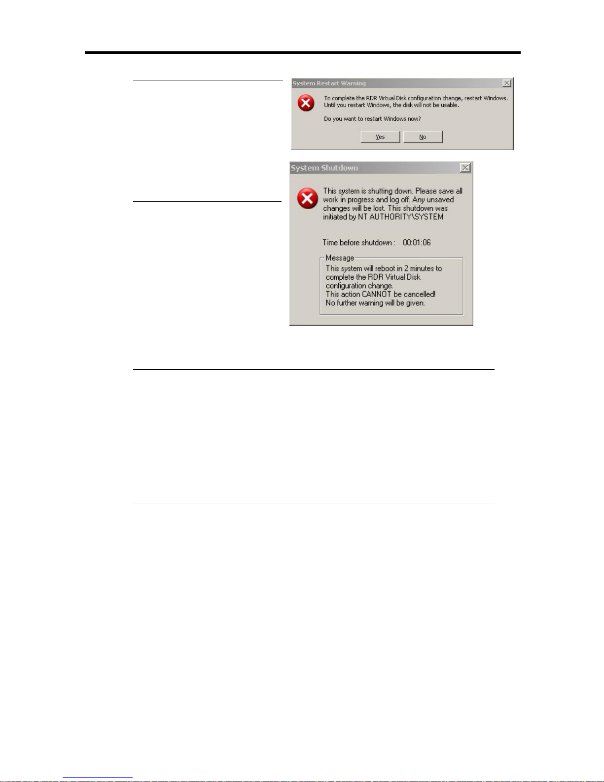
4-41
IMPORTANT:
If you set RDR on the disk that
includes a system partition or a
partition that cannot be
unmounted, the message on the
right is displayed. Click [Yes].
The system is restarted after 2
minutes. After it is restarted,
perform the steps 7and later.
7. Insert the disk to set dual configuration into the slot 1 of PCI module 1, and execute
the procedure 2.
IMPORTANT:
– If a HDD is already mounted, this procedure is not necessary. Proceed to the
procedure 8.
– A popup window may come up when you inserted or initialized the disk;
however, you do not need to restart the system. Select [No] to exit the popup
window.
– As to the disk to be inserted, use a new disk or a physically formatted disk with
the same capacity as the synchronization source disk. If you use other disks,
dual configuration is not set normally.
* As for physical format, refer to “SAS BIOS – Adaptec SAS/SATA – Configuration
Utility” in Chapter 4, “System Configuration” in the separate volume of the User’s
Guide, and perform Format Disk with Disk Utilities
To perform “Low-Level Format,” on the BIOS setup utility, click [Server],
[Monitoring Configuration] and set [Option ROM Scan Monitoring] to [Disabled].
For how to configure the settings, see “System BIOS – SETUP –” in Chapter 4,
“System Configuration” in the separate volume of the User’s Guide.
Page 92
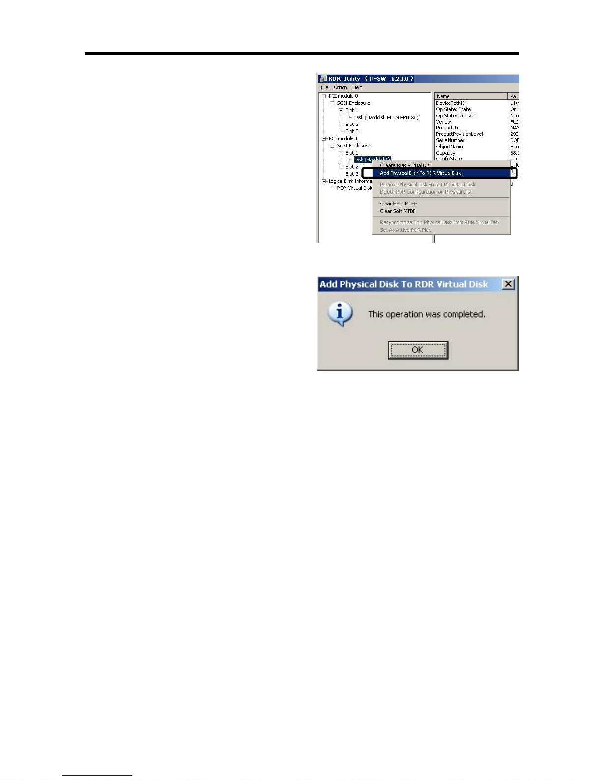
4-42
8. Right-click the Slot 1 of the PCI module 1
from the left pane of RDR Utility, and then
click [Add Physical Disk To RDR Virtual
Disk].
9. Click [OK].
Page 93
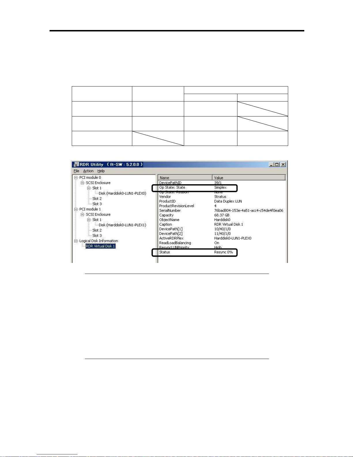
4-43
10. Check that disk synchronization has been started and the status of the DISK ACCESS LED
and RDR Utility display changes as the following table.
During synchronization
RDR Utility
DISK ACCESS
LED
Condition Status
Synchronization
source disk
Amber and
blinking
Simplex
Synchronization
destination disk
Amber and
blinking
Syncing
RDR Virtual Disk
Simplex
Resync x %
(x=0, 4, 8,…, 96)
IMPORTANT:
– The time required for synchronization deffers depending on the size
of the partition that exists on the disk. As for the partition with the
18GB capacity, it takes about 20 minutes. If there is no partition,
synchronization completes soon after setting RDR is completed and
the disk changes to the synchronization completion status.
– Setting dual disk configuration may not complete if the system is
rebooted during synchronization. Do not reboot the system before
synchronization process completes.
Page 94
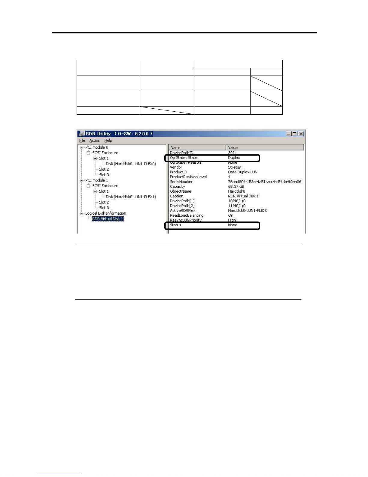
4-44
Synchronization completed
RDR Utility
DISK ACCESS
LED
Condition Status
Synchronization
source disk
Green and
blinking
Duplex
Synchronization
destination disk
Green and
blinking
Duplex
RDR Virtual Disk Duplex None
IMPORTANT:
- If you have created a new partition on the disk where RDR has been set and which
is duplexed, the created partition area is automatically synchronized.
- If the system is not stopped without terminating Windows normally (such as by
pressing the power button), the whole disk area synchronized will be
resynchronized after the system is rebooted.
Page 95

4-45
Step 8: Update Software
If you use ftServer Control Software UPDATE CD-ROM, see “Installing ftServer Control
Software” (page 6-12) to update the software. When there are other update modules, apply them in
this step.
Page 96

4-46
Step 9: Connect and Configure Options
When there are optional PCI boards or peripheral devices to connect to the main unit, power off the
main unit. Then, for connecting them, follow the instructions in “PCI board” in the separate volume
of the User’s Guide and the manual of the devices.
Make dual configuration when you added LAN and disks. For details, see “Step 6 Set Duplex LAN
Configuration” on page 4-31 and “Step 7 Set Dual Disk Configuration” on page 4-38.
Page 97
4-47
Step 10: Create Volume
For Fault Tolerant Server series, you need to perform mirroring for each disk by the RDR function.
If you created a new partition or volume on the disk that has been set RDR and dual configuration,
the area is mirrored automatically. You do not need to perform mirroring for each partition or
volume. For more details about performing mirroring by the RDR function, see “Setting Dual Disk
Configuration by RDR (Rapid Disk Resync) function” in “Step 7: Set Duplex Disk Configuration.”
IMPORTANT:
Do not create any partition/volume on the OS HDD other than the one for the
system.
TIPS:
To create a partition or volume, refer to the Windows online help.
You can create a partition or volume even after the operation has been
started.
Page 98

4-48
Step 11: Set Network for NEC ESMPRO Agent
NEC ESMPRO Agent is required for continuous operation of the Fault Tolerant Server series. It is
automatically installed when you reinstall Windows 2003.
To operate NEC ESMPRO Agent, you need to set the SNMP.
To change the settings of the SNMP Service:
1. Double-click [Administrative Tools] in [Control Panel].
2. Open [Services] in [Administrative Tools].
3. Select [SNMP Service] from the service list and then [Properties] in the [Action] menu.
The “SNMP Properties” dialog box appears.
4. Enter “public” in the [Community name] box in the [Traps] property sheet and click the
[Add to list] button.
IMPORTANT:
If you changed the community name of traps to be received from the default “*” in
the NEC ESMPRO Manager site, enter the same name as the community name
newly set in the NEC ESMPRO Manager site.
To receive trap from NEC ESMPRO Agent at the NEC ESMPRO Manager
machine, both community names should be the same.
5. Click the [Add...] button in [Trap destinations]. After entering the IP address of the NEC
ESMPRO Manager machine of the send destination in the [Host name, IP or IPX address]
box, click the [Add] button.
IMPORTANT: If the IP address (or host name) of the remote NEC ESMPRO
Manager is specified as the trap send destination in the setup of the manager report
(TCP/IP), the message warning the duplication appears. The specification of the same
NEC ESMPRO Manager causes to be reported doubly.
6. Open the [Security] property sheet and make settings as follows:
• Add the community name entered in 4 to [Accepted community names].
• Set its authority to [READ CREATE] or [READ WRITE].
• Select [Accept SNMP packets from any host].
IMPORTANT:
If you entered any community name other than “public” in 4, add that name to
“Accepted Community Names.”
Unless you set the acceptable community’s authority to “READ CREATE” or
“READ WRITE,” you cannot perform monitoring from NEC ESMPRO Manager.
Setup of receiving SNMP packets from specific hosts only
Select [Accept SNMP packets from these hosts], specify IP addresses of the hosts, IP
addresses of the servers to install Agent, and the loop-back address (127.0.0.1).
Page 99

4-49
Setup of receiving SNMP packets from specific communities only
Change the name of the community receiving SNMP packets from the default “public”
to any name.
IMPORTANT:
If the community name is changed, you must change the registered community of
NEC ESMPRO Agent from [Control Panel]. To change the community to another
and register it, use the [SNMP Community] list box in the [General] tab.
To allow NEC ESMPRO Agent to receive SNMP packets sent from NEC
ESMPRO Manager, set the send community name in NEC ESMPRO Manager to
be the same as that accepted by the SNMP Service in NEC ESMPRO Agent.
7. Terminate the network setup.
IMPORTANT:
If the SNMP service is added to the system after the service pack had been applied
at OS installation, apply it again. If not, the SNMP service may not operate
properly. This can cause the improper operation of NEC ESMPRO Agent.
The SNMP Service is required for operating NEC ESMPRO Agent. If the SNMP
Service is deleted after the installation of NEC ESMPRO Agent, install the SNMP
Service and then reinstall NEC ESMPRO Agent.
Some software products provided by other vendors use the SNMP Service. If the
SNMP Service and NEC ESMPRO Agent are installed in the system in which such
software as above is installed, it may be impossible to start NEC ESMPRO Agent
services. If so, delete the SNMP Service once and install the service again. Then,
reinstall NEC ESMPRO Agent and the other vendor's software.
Page 100
4-50
Step 12: Enable OS Boot Monitoring Function
Enable the “OS Boot Monitoring” setting which has been switched at “OS Boot Monitoring” (page
4-10). Refer to “Step 3: Disable OS Boot Monitoring Function“ (page 4-10), change to “Enabled,”
and set appropriate time (default is 10 min.).
Main Advanced Security Server Boot Exit
ftServer Setup
F1 Help ↑↓ Select Item -/+ Change Values F9 Setup Defaults
Esc Exit ←→ Select Menu Enter Select Sub Menu F10 Save and Exit
Monitoring Configuration Item Specific Help
Disables/enables the
FRB-2 Timer.
FRB-2 Timer [Enabled]
PCI Enumeration Monitoring: [Enabled]
PCI Enumeration Monitoring Timeout: [ 180]
Option ROM Scan Monitoring: [Enabled]
Option ROM Scan Monitoring Timeout: [ 300]
OS Boot Monitoring: [Enabled]
OS Boot Monitoring Timeout: [ 600]
POST Pause Monitoring: [Enabled]
POST Pause Monitoring Time-out [ 180]
 Loading...