

Page 1

Bull ESCALA T430 and T450
Setup Guide
System Description, Setup, Use, Standard Maintenance,
Configuration and Upgrading
86 A1 45PX 01
ORDER REFERENCE
Page 2

Page 3

Bull ESCALA T430 and T450
Setup Guide
System Description, Setup, Use, Standard Maintenance,
Configuration and Upgrading
Hardware
February 2000
BULL ELECTRONICS ANGERS
CEDOC
34 Rue du Nid de Pie – BP 428
49004 ANGERS CEDEX 01
FRANCE
86 A1 45PX 01
ORDER REFERENCE
Page 4
The following copyright notice protects this book under the Copyright laws of the United States of America
and other countries which prohibit such actions as, but not limited to, copying, distributing, modifying, and
making derivative works.
Copyright
Bull S.A. 1992, 2000
Printed in France
Suggestions and criticisms concerning the form, content, and presentation of
this book are invited. A form is provided at the end of this book for this purpose.
To order additional copies of this book or other Bull Technical Publications, you
are invited to use the Ordering Form also provided at the end of this book.
Trademarks and Acknowledgements
We acknowledge the right of proprietors of trademarks mentioned in this book.
AIXR is a registered trademark of International Business Machines Corporation, and is being used under
licence.
UNIX is a registered trademark in the United States of America and other countries licensed exclusively through
the Open Group.
Open Firmware is a trademark of FirmWorks.
Year 2000
The product documented in this manual is Year 2000 Ready.
The information in this document is subject to change without notice. Groupe Bull will not be liable for errors
contained herein, or for incidental or consequential damages in connection with the use of this material.
Page 5
Preface
iii
Page 6
Setup Guide
iv
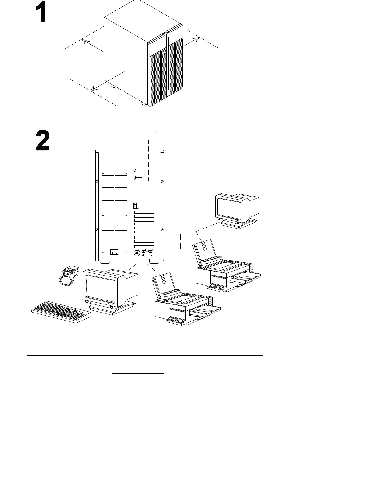
Graphic monitor
ASCII terminal
Parallel printer
508 mm
20 inches
508 mm
20 inches
508 mm
20 inches
RS-485
RS-232
LAN 10/100 Mb/s
Serial printer
Keyboard
Mouse
1
Reference information: Preparing the Site
, on page 1-1
2
Reference information: Connecting Devices
, on page 2-1
Page 7
Preface
v
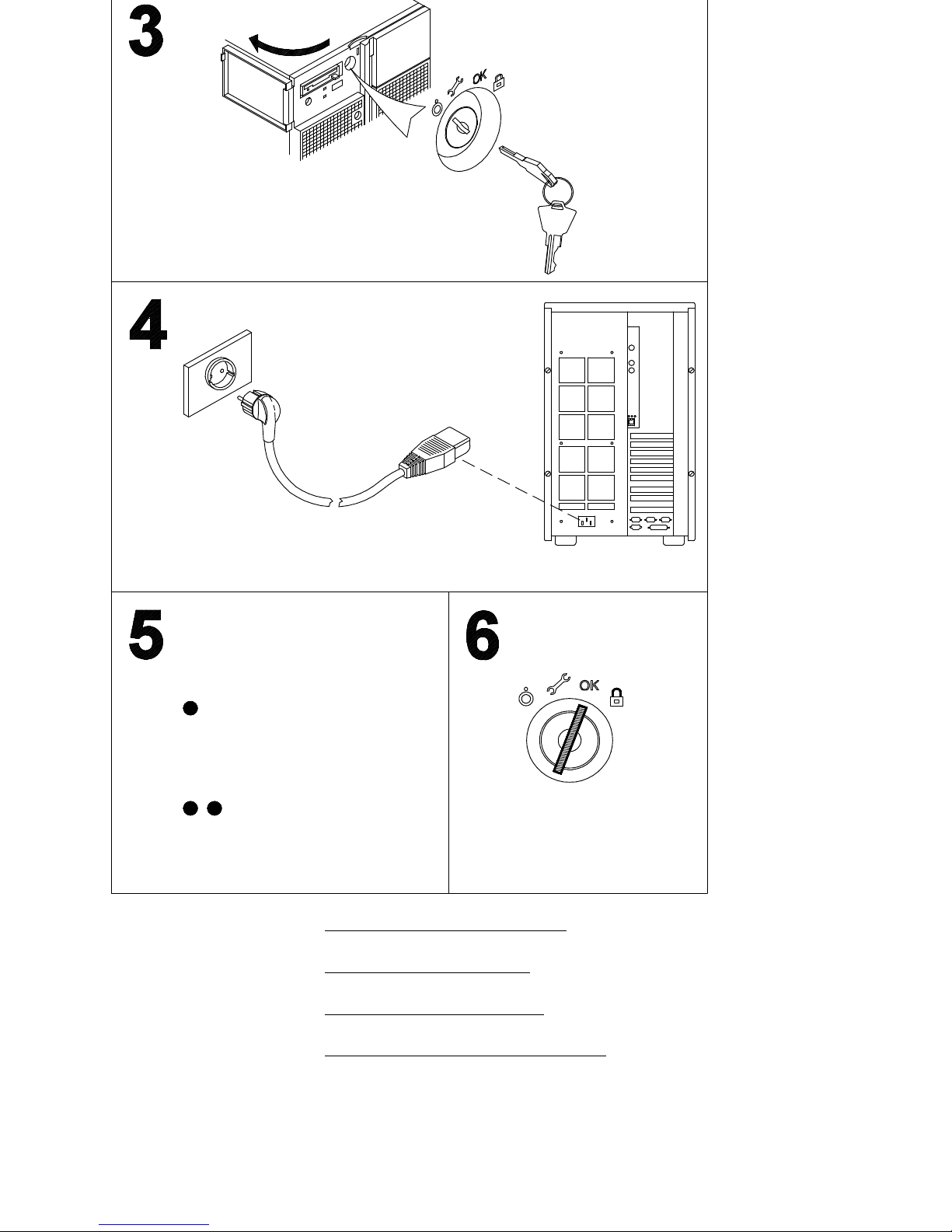
Check the software status for your system
(pre-installed, not-installed).
If the Preload Report sheet has
been supplied with the system,
the software is pre-installed. Skip
to step 6.
If the Preload Report sheet is
not supplied with the system,
the software is not-installed.
Refer to the AIX 4.3 Installation
Guide.
3
Reference information: Inserting the Operator Panel Key
, on page 2-7
4
Reference information: Connecting the Power Cord
, on page 2-9
5
Reference information: Checking the Software Status
, on page 2-10
6
Reference information: First Startup of a Pre-Installed System
, on page 2-11
Page 8

Setup Guide
vi
Page 9

vii
Preface
Table of Contents
Communication Statements ix. . . . . . . . . . . . . . . . . . . . . . . . . . . . . . . . . . . . . . . . . . . . .
Safety Notices x. . . . . . . . . . . . . . . . . . . . . . . . . . . . . . . . . . . . . . . . . . . . . . . . . . . . . . . . . .
What We Do to Protect the Environment xi. . . . . . . . . . . . . . . . . . . . . . . . . . . . . . . . . .
About This Guide xiii. . . . . . . . . . . . . . . . . . . . . . . . . . . . . . . . . . . . . . . . . . . . . . . . . . . . . . .
Chapter 1. Knowing the System 1-1. . . . . . . . . . . . . . . . . . . . . . . . . . . . . . . . . . . . . . . . . .
Preparing the Site 1-1. . . . . . . . . . . . . . . . . . . . . . . . . . . . . . . . . . . . . . . . . . . . . . . . . . . . . . . .
Unpacking and Inspecting the System 1-3. . . . . . . . . . . . . . . . . . . . . . . . . . . . . . . . . . . . . .
System Documentation 1-3. . . . . . . . . . . . . . . . . . . . . . . . . . . . . . . . . . . . . . . . . . . . . . . . . . .
System Presentation 1-7. . . . . . . . . . . . . . . . . . . . . . . . . . . . . . . . . . . . . . . . . . . . . . . . . . . . .
Operator Panel 1-10. . . . . . . . . . . . . . . . . . . . . . . . . . . . . . . . . . . . . . . . . . . . . . . . . . . . . . . . . .
System Features Overview 1-14. . . . . . . . . . . . . . . . . . . . . . . . . . . . . . . . . . . . . . . . . . . . . . . .
Chapter 2. System Setup Procedure 2-1. . . . . . . . . . . . . . . . . . . . . . . . . . . . . . . . . . . . . .
Connecting Devices 2-1. . . . . . . . . . . . . . . . . . . . . . . . . . . . . . . . . . . . . . . . . . . . . . . . . . . . . .
Inserting the Operator Panel Key 2-7. . . . . . . . . . . . . . . . . . . . . . . . . . . . . . . . . . . . . . . . . .
Connecting the Power Cord 2-9. . . . . . . . . . . . . . . . . . . . . . . . . . . . . . . . . . . . . . . . . . . . . . .
Starting the System for the First Time 2-10. . . . . . . . . . . . . . . . . . . . . . . . . . . . . . . . . . . . . . .
Chapter 3. Using Devices and Tools 3-1. . . . . . . . . . . . . . . . . . . . . . . . . . . . . . . . . . . . . .
Using the 3.5-Inch Diskette Drive 3-2. . . . . . . . . . . . . . . . . . . . . . . . . . . . . . . . . . . . . . . . . .
Using the CD-ROM Drive 3-4. . . . . . . . . . . . . . . . . . . . . . . . . . . . . . . . . . . . . . . . . . . . . . . . .
Using the MLR Tape Drive 3-6. . . . . . . . . . . . . . . . . . . . . . . . . . . . . . . . . . . . . . . . . . . . . . . .
Using the 7/14GB 8 mm Tape Drive 3-9. . . . . . . . . . . . . . . . . . . . . . . . . . . . . . . . . . . . . . . .
Using the 4 mm Tape Drive 3-13. . . . . . . . . . . . . . . . . . . . . . . . . . . . . . . . . . . . . . . . . . . . . . .
Using Hard Disk Drives 3-17. . . . . . . . . . . . . . . . . . . . . . . . . . . . . . . . . . . . . . . . . . . . . . . . . . .
Using the Keyboard 3-18. . . . . . . . . . . . . . . . . . . . . . . . . . . . . . . . . . . . . . . . . . . . . . . . . . . . . .
Using the Mouse 3-19. . . . . . . . . . . . . . . . . . . . . . . . . . . . . . . . . . . . . . . . . . . . . . . . . . . . . . . . .
Chapter 4. Maintaining the System 4-1. . . . . . . . . . . . . . . . . . . . . . . . . . . . . . . . . . . . . . .
Starting and Stopping the System 4-1. . . . . . . . . . . . . . . . . . . . . . . . . . . . . . . . . . . . . . . . . .
Maintaining System Configuration Variables 4-4. . . . . . . . . . . . . . . . . . . . . . . . . . . . . . . . .
What is Open Firmware 4-4. . . . . . . . . . . . . . . . . . . . . . . . . . . . . . . . . . . . . . . . . . . . . . . .
How to Access Open Firmware 4-4. . . . . . . . . . . . . . . . . . . . . . . . . . . . . . . . . . . . . . . . . .
Display and Description of the Open Firmware Menu 4-5. . . . . . . . . . . . . . . . . . . . . . .
Problem Solving 4-16. . . . . . . . . . . . . . . . . . . . . . . . . . . . . . . . . . . . . . . . . . . . . . . . . . . . . . . . .
Chapter 5. Configuring the System 5-1. . . . . . . . . . . . . . . . . . . . . . . . . . . . . . . . . . . . . . .
Memory Configuration 5-1. . . . . . . . . . . . . . . . . . . . . . . . . . . . . . . . . . . . . . . . . . . . . . . . . . . .
CPU Configuration 5-3. . . . . . . . . . . . . . . . . . . . . . . . . . . . . . . . . . . . . . . . . . . . . . . . . . . . . . .
Controller Configuration 5-4. . . . . . . . . . . . . . . . . . . . . . . . . . . . . . . . . . . . . . . . . . . . . . . . . .
Device Configuration 5-7. . . . . . . . . . . . . . . . . . . . . . . . . . . . . . . . . . . . . . . . . . . . . . . . . . . . .
Media and Disk Configuration Rules 5-7. . . . . . . . . . . . . . . . . . . . . . . . . . . . . . . . . . . . .
RAID Configurations 5-9. . . . . . . . . . . . . . . . . . . . . . . . . . . . . . . . . . . . . . . . . . . . . . . . . . .
Native High Availability Configurations 5-9. . . . . . . . . . . . . . . . . . . . . . . . . . . . . . . . . . .
SCSI-ID Configuration 5-10. . . . . . . . . . . . . . . . . . . . . . . . . . . . . . . . . . . . . . . . . . . . . . . . .
Examples of SCSI Connections 5-12. . . . . . . . . . . . . . . . . . . . . . . . . . . . . . . . . . . . . . . . .
Page 10

viii
Setup Guide
Chapter 6. Expanding the System Configuration 6-1. . . . . . . . . . . . . . . . . . . . . . . . . .
Preparing the System for an Upgrade 6-1. . . . . . . . . . . . . . . . . . . . . . . . . . . . . . . . . . . . . .
How to Approach the System 6-1. . . . . . . . . . . . . . . . . . . . . . . . . . . . . . . . . . . . . . . . . . .
How to Handle Hardware Components 6-2. . . . . . . . . . . . . . . . . . . . . . . . . . . . . . . . . . .
Preliminary and Restart Operations 6-3. . . . . . . . . . . . . . . . . . . . . . . . . . . . . . . . . . . . . .
Memory Upgrading 6-10. . . . . . . . . . . . . . . . . . . . . . . . . . . . . . . . . . . . . . . . . . . . . . . . . . . . . . .
CPU Upgrading 6-13. . . . . . . . . . . . . . . . . . . . . . . . . . . . . . . . . . . . . . . . . . . . . . . . . . . . . . . . . .
CPU Installation 6-13. . . . . . . . . . . . . . . . . . . . . . . . . . . . . . . . . . . . . . . . . . . . . . . . . . . . . . .
CPU Removal 6-14. . . . . . . . . . . . . . . . . . . . . . . . . . . . . . . . . . . . . . . . . . . . . . . . . . . . . . . . .
Controller Upgrading 6-15. . . . . . . . . . . . . . . . . . . . . . . . . . . . . . . . . . . . . . . . . . . . . . . . . . . . .
Controller Installation 6-15. . . . . . . . . . . . . . . . . . . . . . . . . . . . . . . . . . . . . . . . . . . . . . . . . .
Controller Removal 6-17. . . . . . . . . . . . . . . . . . . . . . . . . . . . . . . . . . . . . . . . . . . . . . . . . . . .
SCSI Controller for Internal Devices 6-18. . . . . . . . . . . . . . . . . . . . . . . . . . . . . . . . . . . . . .
Device Upgrading 6-19. . . . . . . . . . . . . . . . . . . . . . . . . . . . . . . . . . . . . . . . . . . . . . . . . . . . . . . .
Media Drive Installation 6-19. . . . . . . . . . . . . . . . . . . . . . . . . . . . . . . . . . . . . . . . . . . . . . . .
Hard Disk Drive Installation 6-23. . . . . . . . . . . . . . . . . . . . . . . . . . . . . . . . . . . . . . . . . . . . .
Media Drive Removal 6-27. . . . . . . . . . . . . . . . . . . . . . . . . . . . . . . . . . . . . . . . . . . . . . . . . .
Hard Disk Drive Removal 6-30. . . . . . . . . . . . . . . . . . . . . . . . . . . . . . . . . . . . . . . . . . . . . . .
Device Hot Swapping 6-33. . . . . . . . . . . . . . . . . . . . . . . . . . . . . . . . . . . . . . . . . . . . . . . . . .
Adding a Disk Expansion Unit 6-35. . . . . . . . . . . . . . . . . . . . . . . . . . . . . . . . . . . . . . . . . . .
Appendix A. System Specifications A-1. . . . . . . . . . . . . . . . . . . . . . . . . . . . . . . . . . . . . .
Operating Specifications A-1. . . . . . . . . . . . . . . . . . . . . . . . . . . . . . . . . . . . . . . . . . . . . . . . . .
Environment Specifications A-1. . . . . . . . . . . . . . . . . . . . . . . . . . . . . . . . . . . . . . . . . . . . .
Electrical Specifications A-1. . . . . . . . . . . . . . . . . . . . . . . . . . . . . . . . . . . . . . . . . . . . . . . .
Acoustic Noise A-2. . . . . . . . . . . . . . . . . . . . . . . . . . . . . . . . . . . . . . . . . . . . . . . . . . . . . . . . . .
Standards A-2. . . . . . . . . . . . . . . . . . . . . . . . . . . . . . . . . . . . . . . . . . . . . . . . . . . . . . . . . . . . . .
Appendix B. System Devices Location Map B-1. . . . . . . . . . . . . . . . . . . . . . . . . . . . . . .
Glossary G-1. . . . . . . . . . . . . . . . . . . . . . . . . . . . . . . . . . . . . . . . . . . . . . . . . . . . . . . . . . . . . . .
Index X-1. . . . . . . . . . . . . . . . . . . . . . . . . . . . . . . . . . . . . . . . . . . . . . . . . . . . . . . . . . . . . . . . . .
Page 11
ixPreface
Communication Statements
The following statements apply to this product. The statements for other products intended for use with this product
appears in their accompanying manuals.
Federal Communications Commission (FCC) Statement
Note: This equipment has been tested and found to comply with the limits for a Class A digital device, pursuant
to Part 15 of the FCC Rules. These limits are designed to provide reasonable protection against harmful
interference when the equipment is operated in a commercial environment. This equipment generates,
uses, and can radiate radio frequency energy and, if not installed and used in accordance with the
instruction manual, may cause harmful interference to radio communications. Operation of this equipment
in a residential area is likely to cause harmful interference in which case the user will be required to
correct the interference at his own expense.
Properly shielded and grounded cables and connectors must be used in order to meet FCC emission limits. Neither
the provider or the manufacturer are responsible for any radio or television interference caused by using other than
recommended cables and connectors or by unauthorized changes or modifications to this equipment. Unauthorized
changes or modifications could void the user’s authority to operate the equipment.
This device complies with Part 15 of the FCC Rules. Operation is subject to the following two conditions: (1) this
device may not cause harmful interference, and (2) this device must accept any interference received, including
interference that may cause undesired operation.
EC Council Directive
This product is in conformity with the protection requirements of the following EC Council Directives:
• 89/336/EEC and 92/31/EEC (for the electromagnetic compatibility)
• 73/23/EEC (for the low voltage)
• 93/68/EEC (for CE marking).
Neither the provider nor the manufacturer can accept responsibility for any failure to satisfy the protection
requirements resulting from a non-recommended modification of the product, including the fitting of option cards not
supplied by the manufacturer.
International Electrotechnical Commission (IEC) Statement
This product has been designed and built to comply with IEC Standard 950.
Avis de conformité aux normes du ministère des Communications du Canada
Cet appareil numérique de la classe A respecte toutes les exigences du Réglement sur le matériel brouilleur du
Canada.
Canadian Department of Communications Compliance Statement
This Class A digital apparatus meets all requirements of the Canadian Interference Causing Equipment
Regulations.
VCCI Statement
The following is the translation of the VCCI Japanese statement in the box above.
This is a Class A product based on the standard of the Voluntary Control Council for Interferences by Information
Technology Equipment (VCCI). If this equipment is used in a domestic environment, radio disturbance may arise.
When such trouble occurs, the user may be required to take corrective actions.
Page 12

x
Setup Guide
Safety Notices
Definitions of Safety Notices
A danger notice indicates the presence of a hazard that has the potential of causing death or serious personal injury.
A caution notice indicates the presence of a hazard that has the potential of causing moderate or minor personal
injury.
A warning notice indicates an action that could cause damage to a program, device, system, or data.
Placement of Safety Notices Inside This Guide
System safety notices which do not refer to a specific situation are included in these pages. Any specific safety
notices are mentioned inside this guide whenever these must be observed during system operating or handling.
IT Power Systems
This equipment has been designed also for connection to IT Power Systems.
Device Disconnection
To remove the primary power from the unit, unplug the “Appliance Coupler” on the rear side.
Laser Safety Information
Note: The Optical Link Card (OLC) referred to in this information is part of the Serial Optic Channel Converter
assembly.
This system may contain a laser product called the Optical Link Card (OLC). In the U.S., the OLC is certified as a
Class 1 laser product that conforms to the requirements contained in the Department of Health and Human Services
(DHHS) regulation 21 CFR Subchapter J. Internationally, the OLC is certified as a Class 1 laser product that
conforms to the requirements contained in the International Electrotechnical Commission (IEC) standard 825 (1984),
the Verband Deutscher Elektrotechniker (VDE) standard 0837 (1986), and the CENELEC (European Committee for
Electrotechnical Standardization) Harmonization Document HD 482 S1 (1988). The German testing institute VDE
assigned a certificate of conformity to DIN IEC 825/VDE 0837/02.86 and CENELEC HD 482 S1/03.88; the certificate
registration number is 3642.
In addition, Statens Provningsanstalt (Swedish National Testing Institute) tested and approved the OLC for use in
Sweden as a Class 1 laser product and assigned the approval number SP LA 89:184. The CDRH certification label
and the VDE certificate of conformity mark are located on the plastic retainer of the OLC product. The figure shows
the system Class 1 information label required by IEC 825.
Class 1 laser products are not considered to be hazardous. The OLC internally contains a gallium aluminum arsenide
(GaAlAs) semiconductor laser diode emitting in the wavelength range of 770 to 800 nanometers. This laser diode is a
Class 3B laser that is rated at 5.0 milliwatts. The design of the OLC is such that access to laser radiation above a
Class 1 level during operation, user maintenance, or service conditions is prevented.
CLASS 1 LASER PRODUCT
LASER KLASSE 1
LUOKAN 1 LASERLAITE
APPAREIL A LASER DE CLASSE 1
TO IEC 825:1984/CENELEC HD 482 S1
The Optical Link Card (OLC) must only be connected to another OLC or a compatible laser product. Any compatible
laser product must contain the open fiber link detection and laser control safety system used in OLC. This is a
requirement for correct operation of the optical link. In addition, the OLC product is designed and certified for use in
applications with point-to-point optical links only. Using this product in any other type of optical link configuration (for
example, links containing optical splitters or star couplers) is considered as not using the product correctly and may
require that the user certify the laser product again for conformance to the laser safety regulations.
Page 13

xi
Preface
What We Do to Protect the Environment
Your new computer system is implemented following some principles aimed to reduce risks
and harm to the environment, considering the impact that products can have during their life
cycle: production, transport, installation, use at customer site and disposal at end of life.
• Only materials free from dangerous or polluting additives are used (e.g. polybrominated
free material)
• All plastic parts are marked in order to correctly address the recycling operations
• The unit is designed taking into account the requirements for disassembly, largest parts
are made of homogeneous material to facilitate recycling and, where possible,
sub-assemblies are designed to be reused
• Packing is designed with the intent to reduce environmental impacts
• The unit itself does not produce polluting or dangerous emissions (lubricant, solvent, or
other dangerous/polluting substances are not present in the unit)
• Production processes use water-based materials (e.g. paint); for electronic
sub-assemblies, either hydro-soluble fluxes (Freon free) or no clean processes are used.
Page 14

xii
Setup Guide
Page 15

xiii
Preface
About This Guide
Audience
This guide is addressed to people in charge of the setup of the system and its daily
operations.
Note: The upgrading procedures described in this guide (chapter 6) must be performed by
people trained to perform service tasks on the system and must be executed carefully
following the given instructions. The system supplier will not be liable for any problems
deriving from incorrect handling or wrong installation of the upgradings.
Overview of the Contents
Notes:
1. Unless otherwise specified, the information provided in this guide is common to
the system models ESCALA T430 and T450.
2. Being this guide conceived for the setup of several system models and their
never-stopping evolution, it does not include model-specific information, if this is
not relevant to the described procedures. All model-specific characteristics, like
CPU type and speed, model configuration and performances are available on our
internet site at www.bull.com, within the UNIX product description pages.
• Chapter 1, Knowing the System
, guides to preparing the most suitable area to setup
the system and presents system features.
• Chapter 2, System Setup Procedure
, includes any procedures needed to setup the
system and start it for the first time.
• Chapter 3, Using Devices and Tools
, explains how to use system devices and tools
such as CD-ROM, tapes and mouse.
• Chapter 4, Maintaining the System
, describes system starting and stopping procedures
and use of configuration variables; it also includes a simple problem solving table.
• Chapter 5, Configuring the System
, describes the configuration rules of the system, in
terms of disk and media devices, controllers, CPU’s and memory.
• Chapter 6, Expanding the System Configuration
, describes how to upgrade the
system in terms of devices, controllers, CPU’s and memory.
• Appendix A, System Specifications
, summarizes the system specifications and
standards.
• Appendix B, System Devices Location Map
, provides and correlates the different
identifications of the system devices (Open Firmware nodes, physical and logical location
codes).
Related Publications
• Maintenance Guide (86 A1 46PX), provides the description of the system hardware
components and the instructions for their installation and/or replacement. A section is
dedicated to the SCSI cables description and connection. The spare part list is also
included. Moreover, this guide provides information about the system initialization
process, system firmware and configuration variables, and the system features in terms
of reliability, availability and serviceability (RAS). It includes also information about the
maintenance tools provided with the system for diagnostic purposes, such as online and
offline tests, system status indicators (tracing and error codes), remote maintenance.
This guide is addressed to people trained to perform service tasks on the system.
• AIX 4.3 Installation Guide (86 A2 43GX), provides detailed instructions for the AIX
installation.
Page 16

xiv
Setup Guide
• AIX 4.3 System Management Guide: Operating System and Devices (86 A2 99HX),
explains the use of the System Management Interface Tool (SMIT) program.
• Disks and Tapes Configuration Information (86 A1 88GX), describes the setting of
addresses and switches for both disk and tape drives. It also includes information on
CD-ROM drive settings.
• Terminals and Printers Configuration Guide (86 A1 22WE), describes how to configure
terminals, printers and LAN terminal concentrators.
• Terminals and Printers Connections (86 A1 86GX), describes how to connect a terminal
or a printer that is not supplied with the system.
• AIX Problem Solving Guide and Reference (86 A2 32JX), provides information to help
investigate, define and fix problems with the operating system installed on the system. In
particular, the system dump facility and the error log identifiers are described in this
guide.
• AIX Messages Guide and Reference (86 A2 33JX), provides procedures to help
investigate the causes of an error message and how to recover from that error.
• RSF Field Guide (86 A7 96AQ), describes the remote service facilities.
• Bull ESCALA PowerCluster & HA Solutions Setup Guide (86 A2 79HX), describes how to
set up PowerCluster and High Availability solutions; it discuss both the hardware and
software aspects.
In addition, if at least one disk expansion unit is connected to the base unit, the relevant
information can be found in the disk expansion unit specific documentation.
• Disk Expansion Unit Quick Set Up (86 A1 12PX), contains the step by step hardware
procedures for a quick set up of the disk expansion unit.
• Using the Disk Expansion Unit (86 A1 16PX), contains information about the disk
expansion unit operability, features and upgrading.
• Disk Expansion Unit Service Guide (86 A1 13PX), provides the description of the disk
expansion unit hardware components, instructions for their installation and/or
replacement and information about SCSI cables. This guide is addressed to people
trained to perform service tasks on the system.
Adapters Related Publications
The adapters installed in the system are described in separate guides:
• Ethernet 10 & 10/100 Mbps PCI Adapters Installation and Configuration Guide
(86 A1 18GX)
• FDDI Adapters Installation and Configuration Guide (86 A1 53GX)
• PCI High–Resolution Graphics Adapter Installation and Configuration Guide
(86 A1 43HX)
• Token Ring PCI Adapters Installation and Configuration Guide (86 A1 31GX)
• PCI Asynchronous Serial Communications Adapters Installation and Configuration
Guide (86 A1 47AT)
• ISA Internal Modem Installation and Configuration Guide (86 A1 05HX)
• PCI 1Port & 4Port Multi–protocol Serial I/O Adapters Installation & Service Guide
(86 A1 42HX)
• SCSI RAID Adapter Installation and Configuration Guide (86 A1 44HX)
• PCI Fibre Channel Adapters Installation and Configuration Guide (86 A1 95HX)
• PCI 155 Mbps ATM Adapter Installation and User’s Guide (86 A1 86HX).
Page 17

Knowing the System 1-1
Chapter 1. Knowing the System
• Preparing the Site
, below
• Unpacking and Inspecting the System
, on page 1-3
• System Documentation
, on page 1-3
• System Presentation
, on page 1-7
• Operator Panel
, on page 1-10
• System Features Overview
, on page 1-14.
Preparing the Site
Make sure you have an adequate number of proper telephone plugs, grounded electrical
outlets for your system, display, and any other options you intend to install.
Place your system in a location that is dry. Rain or spilled liquids might damage your
system.
Floor
The floor should be made of a durable, antistatic, insulating material which will not produce
or retain dust and can be easily cleaned.
Recommended materials are:
• Laminated material
• Linoleum
• Tiles
• Vinyl.
Materials not to be used are:
• Parquet (produces dust when polished)
• Waxed or glass surfaces (a source of static electricity)
• Carpets (produce and retain dust and are a source of static electricity).
If a carpet is necessary, it must be made of an antistatic material or treated with antistatic
product.
Fire Protection
Fire exstinguishers should be installed in the system room containing carbon dioxide (CO2)
or inert gas. If a water system is used, precautions should be taken to prevent the
accidental turning on of the water.
It is recommended to install smoke and heat detectors.
Page 18
1-2 Setup Guide
Arranging your Office
We offer you some information for adjusting the furniture in your office.
An adjustable chair with comfortable support is suggested, adjust the chair to fit your body
properly.
Your lower back (lumbar region) should be supported correctly by the back of the chair.
Place your monitor slightly below your eyes level when you are sitting at the keyboard.
Keep an adequate distance from your eyes to the screen about 18 - 28 in. (450 - 700 mm).
Position the monitor to minimize glare and reflections on the screen and, if necessary, use
the screen filter to protect against electrostatic discharge.
Keep your screen clean, to reduce unwanted reflections.
Avoiding Fatigue
A non-direct light of about 500 lm/m2 (lumen per square meter) measured at a distance of
750 mm from the floor should be enough to work in comfort.
When you are seated since long time, stand up and take a short break to reduce fatigue
and to relax your eyes.
Physical Dimensions
The table below lists the dimension of the system unit and its weight.
Height 24.8 in. 630 mm off the floor
Width 13.9 in. 353 mm
Depth 19.7 in. 500 mm
Weight 121.4 lbs* 55 kg*
* This value corresponds to a maximum system configuration; i.e. including a max. number
of cards and devices.
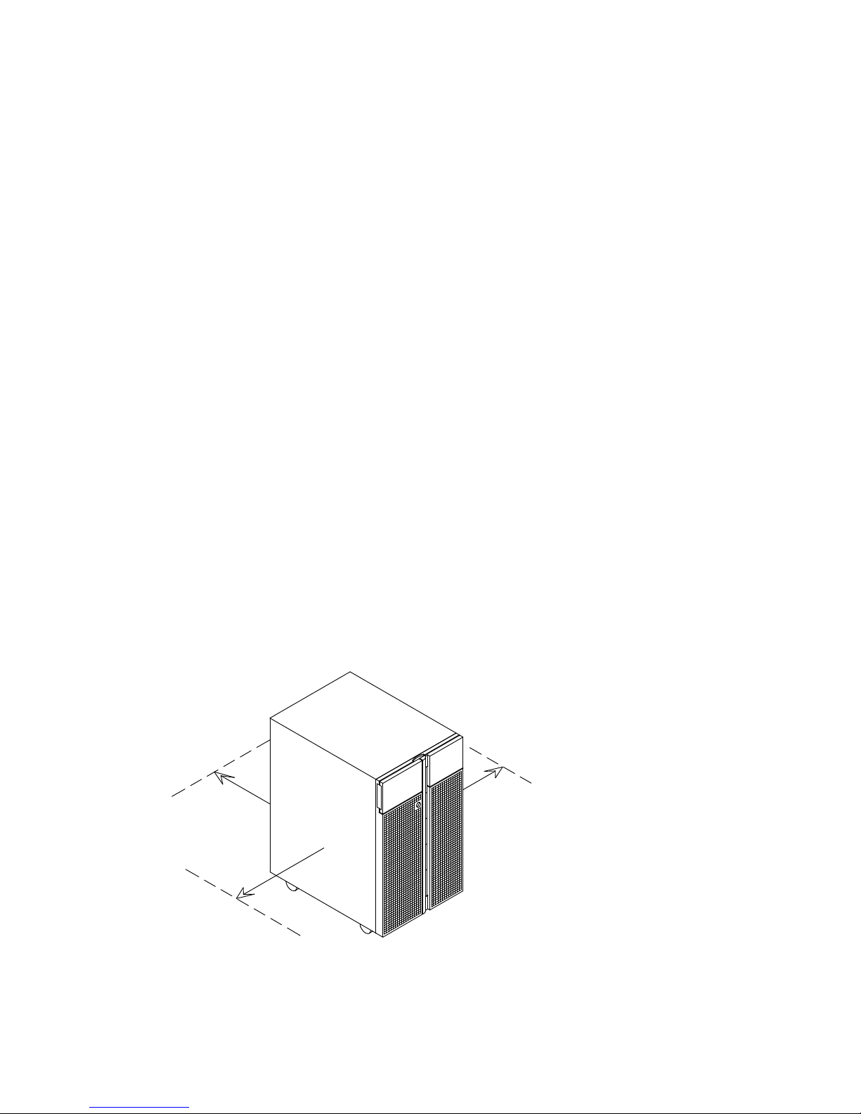
Clearance
The amount of space needed by the system unit during normal operation is indicated in the
figure below.
508 mm
20 inches
508 mm
20 inches
508 mm
20 inches
In addition, before installing the system, you should keep into consideration also the space
that could be necessary on each side for possible service and maintenance.
Page 19

Knowing the System 1-3
Unpacking and Inspecting the System
CAUTION:
To avoid possible injury while moving the system, ask another person to help you.
Move the system to the area that you have chosen.
If not yet done, carefully unpack the system unit and components, following the information
on the shipping box. Save all packing materials so that you can repack the system in case
you ever need to move or ship it.
Your system was checked and carefully packed before it left the manufacturer.
Contact your authorized supplier or marketing representative if any items seem to be
damaged or missing.
System Documentation
The system is shipped with a set of hardware and software manuals, which lead users in
setting up, operating, configuring, upgrading the system and installing software.
These guides constitute the basic documentation set.
Additional documentation is delivered according to the specific products the system is
equipped with.
Some guides are on paper only, some ones are both on paper and on CD-ROM, while other
ones are on CD-ROM only.
Online documentation offers you several advantages:
• You can find the information you need quickly, automatically jumping from one
documentation topic to the others, simply clicking with your mouse on the desired topic
• You can access the information you need from any workstation or terminal connected to
the system, with no need to have paper documentation at hand
• In case you need it, you can print the selected topic.
Refer to the CD-ROM booklet for information on online documentation use.
Maintenance Kit
A maintenance kit including a specific set of paper documentation is available at any
authorized supplier. It is addressed to both service people and trained customers who are in
charge of the system maintenance.
Page 20

1-4 Setup Guide
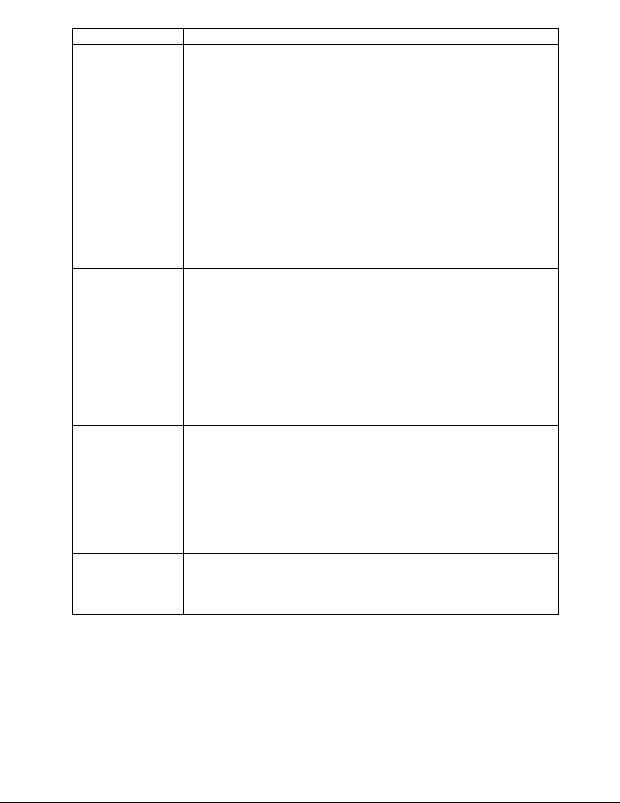
Where Do I Find the Information I Need?
A documentation task roadmap is provided below to help you find the task related
information inside the documentation kit. For each task, the title of guides and sections are
given.
Documentation Task
Reference
System Description
Environment and Safety Considerations
Setup Guide, Knowing the System, → Preparing the Site
System Presentation and Features
Setup Guide, Knowing the System
Operator’s Controls
Operator Panel Description and Key Usage
Setup Guide, Knowing the System, → Operator Panel
Inserting the Opeator Panel Key
Setup Guide, System Setup Procedure
Starting and Stopping the Ststem
Setup Guide, Maintaining the System
System Panels
Device Shutter, Front and Lateral Panels
Setup Guide, Expanding the System Configuration, → Preliminary and Restart
Operations
Media and Disk
Devices
Device Areas Description
Setup Guide, Configuring the System, → Device Configuration and
Using the Disk Expansion Unit, Disk Expansion Unit Configuration
Drives Configuration and SCSI-ID
Setup Guide, Configuring the System, → SCSI-ID Configuration
and
Using the Disk Expansion Unit, Disk Expansion Unit Configuration
and
Disks and Tapes Configuration Information, the paragraph related to your drive model
SCSI Connection and Configuration (maintenance task)
Maintenance Guide, SCSI Cables Description and Connection and
Disk Expansion Unit Service Guide, SCSI Cables Description and Connection
Disks and Drives Description, Usage and Preventive Maintenance
Setup Guide, Using Devices and Tools
Upgrading / Removal
Setup Guide, Expanding the System Configuration
3.5-Inch Diskette Installation and Removal (maintenance task)
Maintenance Guide, Hardware Maintenance
Disk Cage Installation and Removal (maintenance task)
Maintenance Guide, Hardware Maintenance
Disk Expansion Unit Service Guide, Disk Expansion Unit Hardware Maintenance
Page 21
Knowing the System 1-5
Documentation Task
Reference
Peripherals
Keyboard / Mouse
• Connection
Setup Guide, System Setup Procedure, → Connecting Devices
• Usage
Setup Guide, Using Devices and Tools
• Problems with the Keyboard / Mouse
Setup Guide, Maintaining the System, → Problem Solving
Terminal / Printer:
• Connection
Setup Guide, System Setup Procedure, → Connecting Devices
• Setup
Terminals and Printers Configuration Guide and Terminal and Printer Connections
• Problems with the Terminal / Printer
Setup Guide, Maintaining the System, → Problem Solving
Memory
Description / Configuration
Setup Guide, Configuring the System
Upgrading / Removal
Setup Guide, Expanding the System Configuration
Handling of Single Memory Errors (maintenance task)
Maintenance Guide, Handling of Single Memory Errors
CPU Cards
Description / Configuration
Setup Guide, Configuring the System
Upgrading / Removal
Setup Guide, Expanding the System Configuration
Controllers
Description / Configuration
Setup Guide, Configuring the System
Upgrading / Removal
Setup Guide, Expanding the System Configuration
PCI/ISA Busses and Devices Description and Location
Setup Guide, System Devices Location Map, → PCI/ISA Busses and Devices
PCI/ISA Controllers Supported by the System
Setup Guide, Configuring the System, → Controller Configuration
Disk Expansion Unit
Description / Configuration
Using the Disk Expansion Unit
External Connections
Disk Expansion Unit Quick Set Up
Page 22

1-6 Setup Guide
Documentation Task
Reference
General Maintenance
Features
How to Handle Hardware Components
Maintenance Guide, Hardware Maintenance, → Preliminary and Restart Operations
Running Offline Tests
Maintenance Guide, Offline Diagnostics
Running Online Tests
Maintenance Guide, AIX Online Diagnostics
Maintenance Guide, Some Useful AIX Commands
System States, Operator Panel Codes and System Messages
Maintenance Guide, System Status Indicators
Remote Maintenance
Maintenance Guide, Remote Maintenance
Service Lines
Maintenance Guide, System Initialization Process Overview
Firmware Updating
Maintenance Guide, Firmware Updating
System Configuration Variables and Flags
Setup Guide, Maintaining the System (Open Firmware)
Maintenance Guide, System Configuration Variables and Flags
(Stand-By Menu and Open Firmware)
Handling of a Dead System
Maintenance Guide, Handling of a Dead System
Handling of Power and Fan Errors
Maintenance Guide, Handling of Power and Fan Errors
Handling of Memory Errors
Maintenance Guide, Handling of Single Memory Errors
Spare Parts List
Maintenance Guide, Spare Parts
Specific Maintenance for
the Base Unit
Description of the Hardware Components and Internal Connectors
Maintenance Guide, Hardware Maintenance, → List of the Hardware Components
Faulty Component Replacement
Maintenance Guide, Hardware Maintenance
SCSI Connections and Configuration Examples
Maintenance Guide, SCSI Cables Description and Connection
Specific Maintenance for
the Disk Expansion Unit
Description of the Hardware Components and Internal Connectors
Disk Expansion Unit Service Guide, Disk Expansion Unit Hardware Components
Adding a Disk Expansion Unit
Disk Expansion Unit Quick Set Up
Faulty Component Replacement
Disk Expansion Unit Service Guide, Disk Expansion Unit Hardware Maintenance
SCSI Connections and Configuration Examples
Disk Expansion Unit Service Guide, SCSI Cables Description and Connection
Page 23
Knowing the System 1-7
System Presentation
Your new system is a powerful computer, easy to use and easy to maintain.
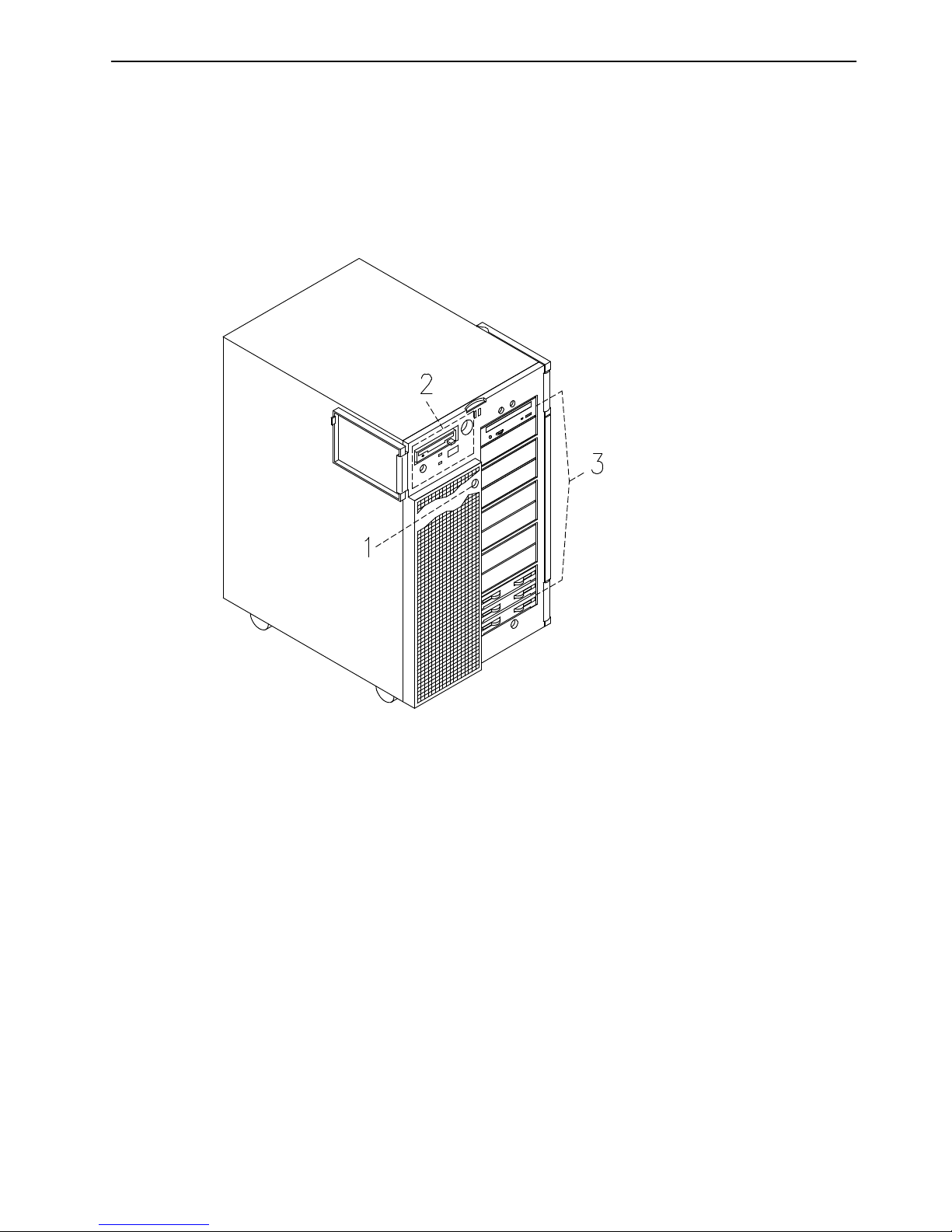
Front View of the Base Unit
The system operator’s controls are on the front side of the base unit protected by two
shutters.
The first shutter covers the operator panel and floppy drive area (left side of the unit), the
second one covers the media and disk devices area (right side of the unit).
1
Device shutter key lock: the key lock used to lock the device shutter
2
Operator panel: the operator’s control panel
3
Media and disk devices area: the area where the operator can access these devices
Page 24
1-8 Setup Guide
Rear View of the Base Unit
Connectors:
1
RS-485: for expansion unit connection
2
Mouse: 6-pin mini-DIN female
3
Keyboard: 6-pin mini-DIN female
4
Three (green) LAN LED’s
, from right to left: speed, link and half
or full duplex connection
5
Transmit data (green) LED
6
Receive data (green) LED
7
LAN 10/100 M-bit: RJ-45
8
Three serial RS-232 ports 9-pin male, from right to left: COM1,
COM2 and COM3
9
Parallel port: 25-pin female
10
Video graphics: SVGA 15-pin female
11
Power cord receptacle
Page 25
Knowing the System 1-9
Three LAN LED’s, Transmit Data and Receive Data LED’s
• 100Mb
– Light on: 100 M-bit connection
– Light off: 10 M-bit connection.
• LINK
– Light on: cable plugged in the RJ-45 connector
– Light off: no cable in the RJ-45 connector.
• FDX
– Light on: full duplex connection
– Light off: half duplex connection.
• TX
– Light on or blinking: transmit data activity
– Light off: no transmit data activity.
• RX
– Light on or blinking: receive data activity
– Light off: no receive data activity.
Page 26
1-10 Setup Guide
Operator Panel
The operator panel is installed in the front of the unit.
Operator Controls:
1
Reset Button
, below
2
3.5-Inch Diskette Drive
, on page 3-2
3
Key Mode Switch
, on page 1-11
4
Hexadecimal Display
, on page 1-12
5
LED’s
, on page 1-13
Reset Button
The reset button is located on the operator panel and is used to reset the system. It is
active when the key mode switch is in the Normal or in the Service position.
It is disabled when the key mode switch is in the Secure and Power Off position.
Warning: Pressing the reset button can cause data to be damaged or lost if the operating
system is still running.
The reset button is used to:
• Reset the system unit (double click) and cause a boot when the key mode switch is set
to the Normal or to the Service position
• Start the dump program (single click) when a manual dump is needed
• Start the system unit without executing the extended initialization tests (single click just
before moving the key mode switch from the Power Off position to the Normal position or
Service position).
Page 27
Knowing the System 1-11
Key Mode Switch
The key mode switch provides four logical functions, which are enabled only when AC
power is present in the base unit.
The four logical functions are:
Power Off
Service
Normal
Secure
The key can be removed only in the Power Off and Secure positions. The key is locked in
the Normal and Service positions for safety reasons.
The following table summarizes the available operations for each key mode switch position:
Note: During remote maintenance sessions the position of the key is not meaningful. All
operations listed in the table can be performed.
Operation
Key Mode Switch Position
Power Off Service Normal Secure
Use of the BUMP Console Yes Yes Yes Yes
Access Open Firmware No Yes
(1)
Yes
(1)
No
Take a Dump No Yes No No
Reset No Yes Yes No
Do an Automatic Boot No Yes
(2)
Yes No
Do an Interactive Boot No Yes Yes No
Run a Remote Maintenance
session
(3)
Yes Yes Yes Yes
Notes:
1. During power on phase only.
2. Enter the diagnostic menu under operating system.
3. The position of the key is not meaningful during remote maintenance session.
Page 28

1-12 Setup Guide
Power Off Position:
This is the standby position. The system is not working but it is possible to call the standby
menu for offline maintenance purposes.
Service Position:
The Service position can be used either to do an automatic or an interactive power on,
depending on the value of the Open Firmware auto-boot? variable (true by default, it performs
an automatic boot). When the system is powered on with the key in this position, the operating
system diagnostic mode is entered. Moreover, this position is used for some offline
maintenance activities (e.g. offline test running).
Normal Position:
The Normal position is for normal system operations. It can be used either to do an
automatic or an interactive power on, depending on the value of the Open Firmware
auto-boot? variable (true by default, it performs an automatic boot).
Secure Position:
The Secure position prevents the system from booting. If the system is already booted, this
position does not lock the system console or block system network communication.
When the operating system is up, turning the key to the Secure position disables the reset
button. With the key mode switch in this position, a passerby cannot accidentally press the
reset button and cause a loss of data.
Hexadecimal Display
The hexadecimal display visualizes the status of the system (standby, testing, error).
If you want to have a description of the hexadecimal display codes, refer to System Status
Indicators, in the Maintenance Guide. This guide is available at your supplier.
In case you are not maintaining the system on your own and encounter an error (a flashing
code on the display), follow the instructions described in Problem Solving
, on page 4-16.
What the hexadecimal display shows and the way it shows it (blinking, steady), depends on
the system status:
• Tracing:
– During the power on phases the hexadecimal display shows, without blinking, the test
code of the test under execution.
• Fault Detection:
– In case of fault detected by the system, the code displayed on the hexadecimal
display either flashes or remains steady on the display for more than two minutes.
• Power On phase completed correctly:
– The hexadecimal display is cleared.
Page 29

Knowing the System 1-13
LED’s
The system base unit provides two LED’s which are located on the operator panel.
GREEN
YELLOW
Status Light States
• The Yellow LED, when lit, indicates that the power on self-tests have been completed
without errors and that the system is working under control of the operating system
• The Green LED, when lit, indicates that all voltages in the power supply are present and
within specified limits and that all fans are running.
Page 30

1-14 Setup Guide
System Features Overview
Base Unit Features
The following list summarizes the features provided by the system base unit:
Integrated Features
• Two native SCSI busses
– One ULTRA/SE bus (for media drives)
– One ULTRA-2/LVD bus (for hard disk drives).
• One LAN (RJ-45) controller at 10M bits and 100M bits
• One video graphics adapter (SVGA) with internal power save control and 2M bytes of
video memory
• Three RS-232 standard communication lines
• One parallel port
• One mouse port
• One keyboard port
• One EIA-485 communication line
• One redundant power supply
• Support for an integrated modem using the ISA slot.
Hard Disk Drives
• Up to twelve 1-inch ULTRA-2/LVD hard disks.
Media Drives
• One floppy diskette drive
• Up to four media devices, such as CD-ROM, 4 mm/8 mm tape, MLR tape.
PCI/ISA Controllers
• Up to nine PCI cards
• One ISA card.
Memory
• From 256M bytes to 8G bytes.
CPU’s
• Up to four CPU cards.
Operating System
• AIX 4.3 or higher.
Disk Expansion Unit
• Up to two disk expansion units.
Disk Expansion Unit Features
Hard Disk Drives
• Up to twelve 1-inch hard disks.
Media Drives
• Up to two media devices, such as CD-ROM, 4 mm/8 mm tape, MLR tape.
Page 31

System Setup Procedure 2-1
Chapter 2. System Setup Procedure
Perform all the procedures described in this section in the indicated order to setup the
system and make it operational.
• Connecting Devices
, below
• Inserting the Operator Panel Key
, on page 2-7
• Connecting the Power Cord
, on page 2-9
• Starting the System for the First Time
, on page 2-10.
Note: If you need to connect expansion units to the system base unit, proceed as follows:
1. Set up the system base unit, start it for the first time and make sure that no errors
are detected during the initial start up, following the procedures described in this
section.
2. When you are sure that the system base unit operates correctly, perform the
installation and connection of the expansion units:
– For the disk expansion units, please refer to the Disk Expansion Unit Quick Set
Up leaflet
– For other expansion units, please refer to the documentation delivered with
those units.
Connecting Devices
The following paragraphs explain how to physically connect devices to the system.
• Connecting Terminals
, on page 2-2
• Connecting Keyboard and Mouse, on page 2-4
• Connecting Printers
, on page 2-5
• Connecting PCI Controller Cables
, on page 2-6.
DANGER
When adding or removing any additional devices to or from the system,
ensure that the power cables for those devices are unplugged before the
signal cables are connected. If possible, disconnect all power cables from
the existing system before you add a device.
Use one hand, when possible, to connect or disconnect signal cables to
prevent a possible shock from touching two surfaces with different electrical
potentials.
During an electrical storm, do not connect cables for display stations,
printers, telephones, or station protectors for communication lines.
Page 32
2-2 Setup Guide
Connecting Terminals
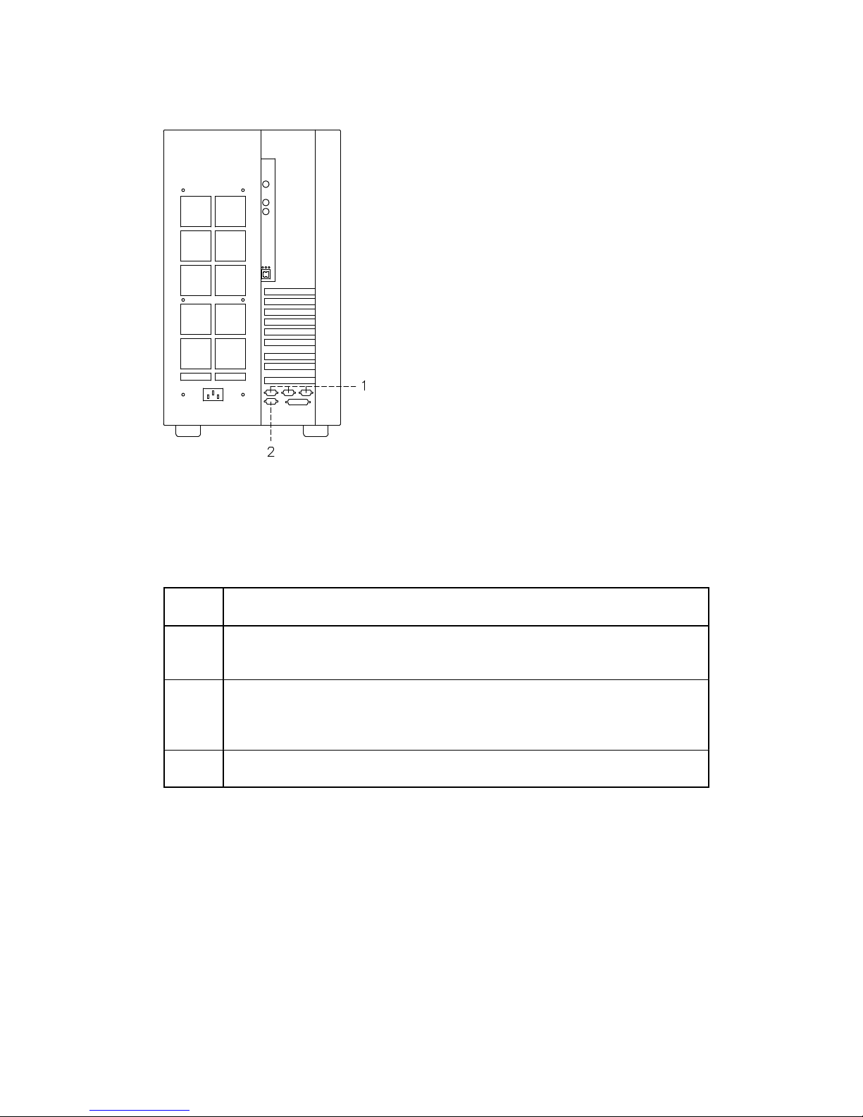
The figure indicates the three serial ports and the SVGA port:
System Rear Side
1
From right to left: COM1, COM2, COM3 serial ports
2
SVGA port
The following table summarizes the function of the terminal ports available on the system:
COM1
Used to connect an ASCII terminal. This terminal is called BUMP console.
The Stand-By menu is available only on the terminal connected to this port.
COM2 Used to remotely connect, via an external modem, an ASCII terminal to be
used for remote maintenance by customer service centers.
It can also be used as a normal RS-232 serial line.
COM3 Used as a normal RS-232 serial line. It can also be used to connect an
external UPS device (Uninterruptible Power Supply). The UPS, if present,
provides continuous power to the system and sustains it in case of outages,
for a given amount of time.
SVGA Used to connect a graphic display monitor which is defined, by default, as
the Open Firmware console.
Page 33

System Setup Procedure 2-3
Perform the following steps to physically connect any terminals to the system:
1. Connect the terminal to the proper port on the rear of the unit, as follows:
a. If you have a graphic monitor, connect it to the SVGA port.
b. If you have an ASCII terminal, connect it to the COM1 serial port (BUMP console) or
to any other free serial port.
2. Connect the terminal(s) power cord(s) to the proper power outlet(s).
Once you have connected the required terminal(s), decide which one you want to use as
the system console:
• If it is a graphic terminal, no additional operation is required
• If it is an ASCII terminal, you need to:
– Switch the terminal on
– Press the appropriate key to activate the terminal setup menu
Note: For information about the key(s) used to activate the terminal setup menu and how
to set the required options, refer to the terminal specific documentation.
– Check that the following options are set as specified below:
Communication Options
Line Speed (baud rate) 9600
Word Length (bits per character) 8
Parity no (none)
Number of Stop Bits 2
Interface RS-232C (or RS-422A)
Line Control IPRTS
Keyboard and Display Options
Screen normal
Row and Column 24x80
Scroll jump
Auto LF (line feed) off
Line Wrap on
Forcing Insert line (or both)
Tab field
Operating Mode echo
Turnaround Character CR
Enter return
Return new line
New Line CR
Send page
Insert Character space
– After having successfully completed the console setup, you may switch it off.
Note: Remember that the above settings must be performed for all ASCII terminals
connected to the system, before you use them. Refer to the specific terminal
documentation for detailed information.
Page 34
2-4 Setup Guide
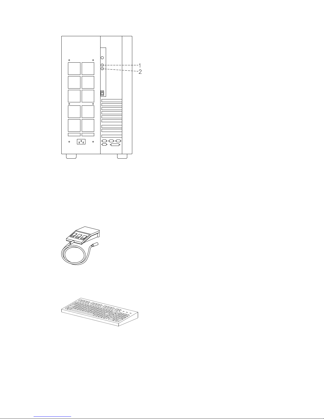
Connecting Keyboard and Mouse
System Rear Side
1
Mouse
2
Keyboard
Note: Keyboard and mouse are for use with graphic monitors only. You do not need to
connect them, if you are not going to connect any graphic monitor.
Connect the mouse to the dedicated connector at the rear of the base unit. Do not force the
cable plug into the socket.
Connect the keyboard to the dedicated connector at the rear of the base unit. Do not force
the cable plug into the socket.
Page 35
System Setup Procedure 2-5
Connecting Printers
If you need to connect a printer to the system:
1. Connect the printer to the proper connector on the rear of the base unit, as follows:
– If you are going to use it as a parallel printer, connect it to the enhanced parallel
connector
– If you are going to use it as a serial printer, connect it to one of the serial connectors
(RS-232 ports).
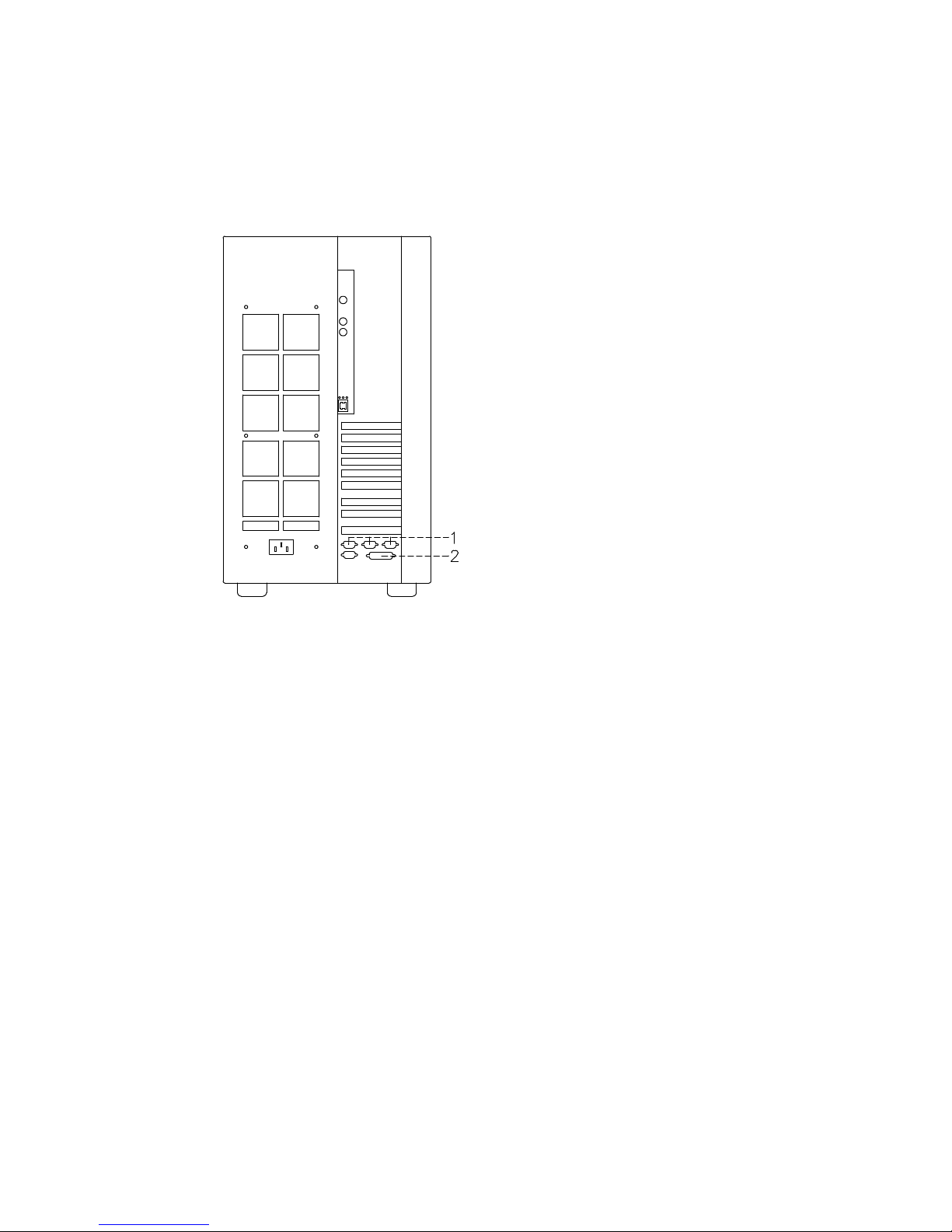
System Rear Side
1
Serial ports
2
Parallel port
You can also connect printers to a SCSI port (if PCI controllers housing SCSI ports are
installed inside the system unit), and to the Ethernet network using either the native
connector or external ones.
2. Connect the printer power cord first to the printer itself and then to a power outlet.
For further information about your printer connection and configuration, please refer to the
documentation provided with the printer itself and to the Terminals and Printers
Configuration Guide.
Page 36

2-6 Setup Guide
Connecting PCI Controller Cables
If you need to connect one or more PCI controller cables for external connections, please
refer to the specific documentation delivered with each controller.
If you need to connect SCSI cables, refer to the Maintenance Guide or to the Disk
Expansion Unit Service Guide, for disk expansion unit SCSI connections.
Page 37
System Setup Procedure 2-7
Inserting the Operator Panel Key
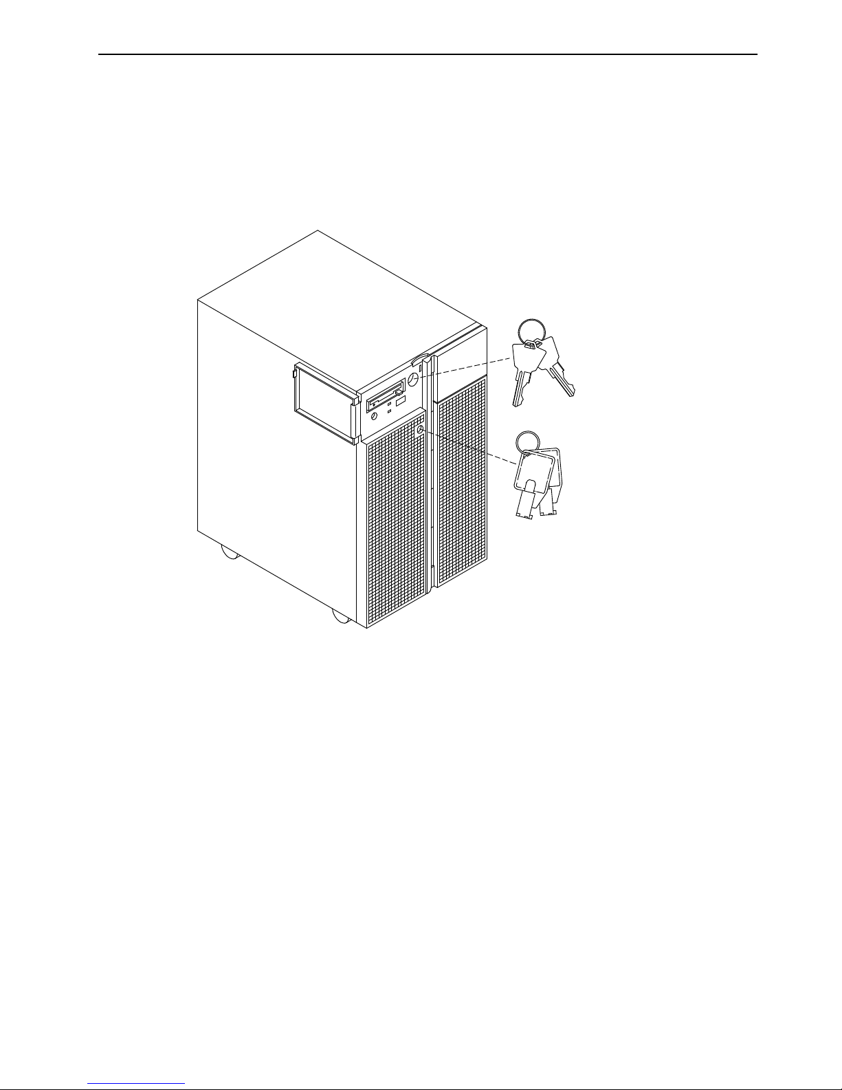
Two pairs of keys are supplied with the system.
One pair is used as the operator panel key which enables the power on/off function and the
operation mode. These functions are managed by the key controlled switch which is named
key mode switch.
The second pair of keys is used to mechanically lock/unlock the device shutter.
Operator Panel Keys
Device Shutter Keys
Put the device shutter keys in a safe place because these are not needed now. To go on
with the system setup procedure you are required only to insert one of the operator panel
keys in the key mode switch.
Page 38
2-8 Setup Guide
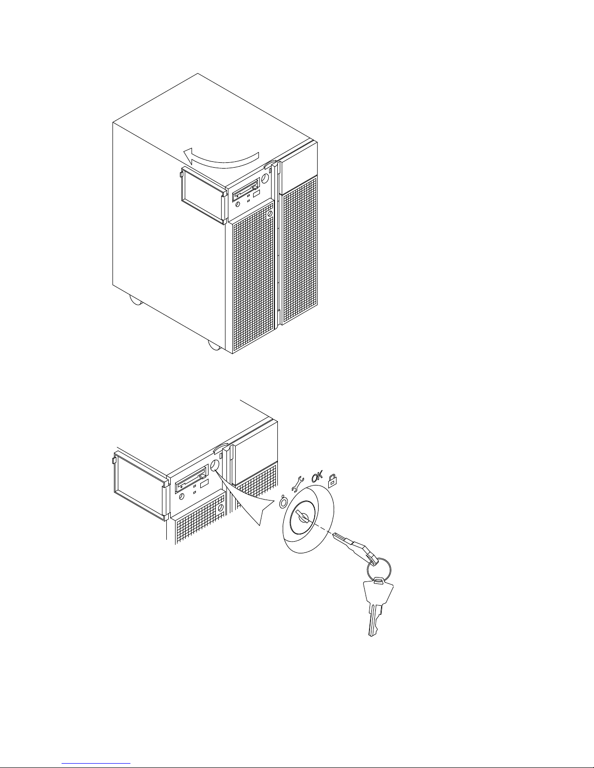
Insert the operator panel key performing the following steps:
1. Gain access to the operator panel firmly gripping the front bezel and opening it to the
left.
2. Insert the operator panel key in the key mode switch in the position shown in the figure.
Page 39
System Setup Procedure 2-9
Connecting the Power Cord
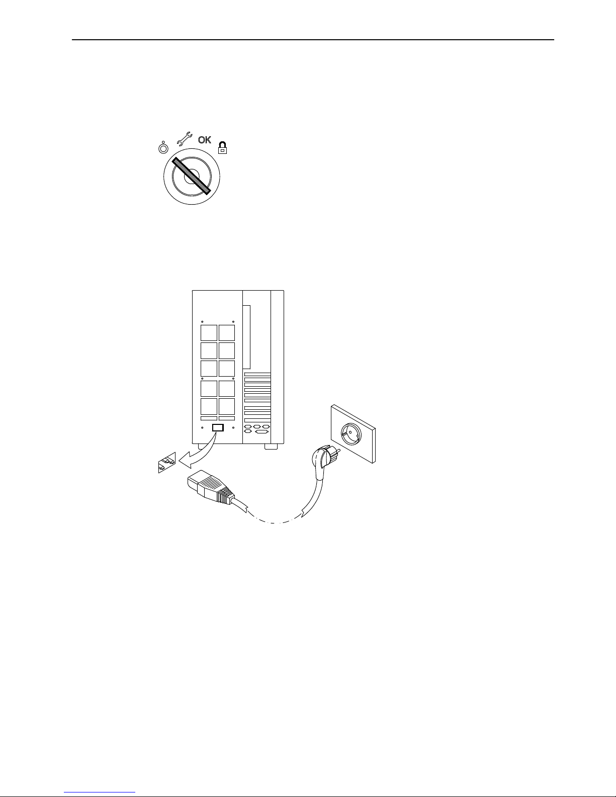
Before performing the first startup of the system, the following steps must be performed to
give it AC power.
1. Make sure that the key mode switch is set to the Power Off position and all external
devices connected to the system are powered off.
2. Identify the power receptacle toward the bottom of the rear of the system.
3. Connect the power cord supplied with the system, first to the system unit, and then to
the wall outlet as shown in the figure.
CAUTION:
An electrical outlet that is not correctly wired could place hazardous voltage on metal
parts of the system or the devices that attach to the system. It is the responsibility of
the customer to ensure that the outlet is correctly wired and grounded to prevent an
electrical shock.
Page 40

2-10 Setup Guide
Starting the System for the First Time
• Checking the Software Status
, below
• First Startup of a Pre-Installed System
, on page 2-11.
Checking the Software Status
The software for your system can be:
• Pre-installed
• Not-installed.
By default, the system software is pre-installed on your system, when you receive it. This
makes the first startup of the system easier and faster.
Make sure the system software is pre-installed, by checking that the Preload Report sheet
has been supplied with the system unit. This is a one sheet document which indicates
where you can find the preload report file on the system disk.
Note: Once the system is running, you can list the installed software with the command:
lslpp -l | pg
In case the system software is not installed, refer to the AIX Installation Guide.
Page 41

System Setup Procedure 2-11
First Startup of a Pre-Installed System
If your system is pre-installed, you only need to perform some simple customization tasks
the first time you power it on. These are tasks like setting time and date, setting root
password, create users. A guided program, called Installation Assistant, leads you through
the required steps. A contextual help is included in the program.
1. Be sure that you have connected all external devices to the system unit and all power
cords (including the system unit one) to the proper power outlets, as previously
described in this guide.
2. Power on all external devices (e.g., terminals and printers).
3. Power on the system unit setting the key mode switch to the Normal position.
4. After some minutes, each terminal connected to the system displays a screen asking
you to identify your system console. A specific key is indicated for each terminal. Press
the specified key on the terminal you want to use as the system console. Press a key on
only one terminal.
5. The startup procedure continues up to the display of the login prompt. Type root and
press the Enter key or click on the OK button. If you are using a graphic monitor go to
step 6, otherwise skip to step 7.
6. Open a window on your desktop.
7. Type install_assist and press the Enter key.
8. The Installation Assistant screen appears. Execute the tasks that apply to your system
in the order they are listed. If you need information on the tasks, use the program help.
You can also find further information on the Installation Assistant program in the AIX
Installation Guide.
9. When all the needed tasks are completed, exit to the operating system login prompt,
through the Tasks Completed selection of the program.
If you need information on the operating system licenses, please refer to the AIX Installation
Guide.
The system is ready to work.
Page 42

2-12 Setup Guide
Page 43

3-1
Using Devices and Tools
Chapter 3. Using Devices and Tools
This section gives a brief description of the supported devices and tools and explains how
to work with them. For details on device characteristics, such as capacity, speed, transfer
rate, please refer to Disks and Tapes Configuration Information guide, delivered with the
system.
• Using the 3.5-Inch Diskette Drive, on page 3-2
• Using the CD-ROM Drive
, on page 3-4
• Using the MLR Tape Drive
, on page 3-6
• Using the 7/14 GB 8 mm Tape Drive
, on page 3-9
• Using the 4 mm Tape Drive
, on page 3-13
• Using Hard Disk Drives
, on page 3-17
• Using the Keyboard
, on page 3-18
• Using the Mouse
, on page 3-19.
Page 44
3-2
Setup Guide
Using the 3.5-Inch Diskette Drive
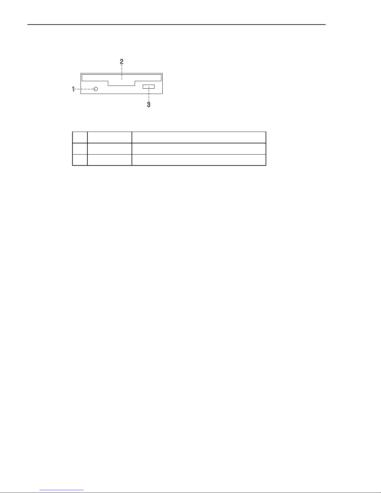
Functions
1
In-use light Lights when the system is accessing the drive
2
Diskette slot Where the diskette is inserted
3
Unload button Used to unload the diskette from the drive
Note: Do not stop the system unit or remove a diskette when the in-use light is on, or you
may lose some of the data on the diskette.
Loading and Unloading the 3.5-Inch Diskette
To load a diskette into the drive, first insert the diskette in the diskette drive with the labeled
metal shutter facing upward and with the bevelled corner on your right and away from you.
Push the diskette into the drive until you hear a click. The click indicates that the diskette is
securely positioned in the drive.
To unload the diskette, push the unload button. The diskette ejects partially so that you can
pull it out.
Page 45
3-3
Using Devices and Tools
Types of 3.5-Inch Diskettes
Warning: Diskette drives and diskettes must be the correct type to store data successfully.
If you use the wrong diskette in your 3.5-inch diskette drive, the data on the diskette could
be destroyed.
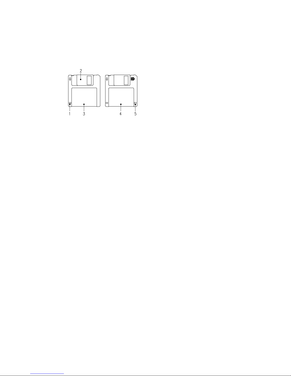
The diskette drive uses the following 3.5-inch diskettes:
• 1.0M-Byte capacity (stores approximately 720K Bytes of data)
• 2.0M-Byte capacity (stores approximately 1.44M Bytes of data).
1
Write-protect slot
2
Sliding metal shutter
3
1.0M-Byte diskette
4
2.0M-Byte diskette
5
Rectangular cutout (only for 2.0M-Byte diskette)
Setting the Write-Protect Tab
Write-protecting diskettes is necessary to avoid data loss.
When diskettes are write-protected, you can read data from the diskettes, but you cannot
write data on them.
There is a write-protect tab on the 3.5-inch diskette.
To locate the write-protect tab, turn the diskette over with the label facing down.
To prevent writing on a diskette, slide down the write-protect tab to open the protect slot.
To allow writing on a diskette, slide up the write-protect tab to cover the protect slot.
Handling 3.5-Inch Diskettes
Be careful with your diskettes. Because each piece of information occupies such a small
area on the diskette, small scratches, dust, food, or tobacco particles can make the
information unusable. Be sure to remember the following:
• Do not touch the recording surfaces
• Keep diskettes away from magnets and magnetic field sources such as telephones,
dictation equipment and electronic calculators
• Keep diskettes away from extreme heat and cold; the recommended temperature range
is 10°C to 60°C (50°F to 140°F)
• Proper care helps prevent loss of data
• Make backup copies of your diskettes regularly.
Page 46
3-4
Setup Guide
Using the CD-ROM Drive
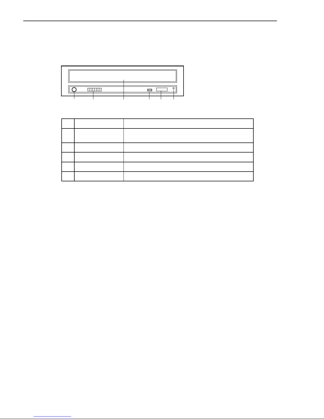
The internal CD-ROM drive is a read-only optical compact disk drive.
Functions
1 2 3 4 5 6
1
Headphone socket
Used for connect headphones to your CD-ROM drive
2
Volume control Used to control the level of the audio signal from the
headphone socket
3
Drive door Prevents dust from entering into the drive
4
Busy LED indicator Used to indicate the condition of the drive
5
Unload button Used to open the disk tray
6
Emergency eject Used to manually open the disk tray
When the CD-ROM is set to on, the LED indicates one of the several conditions.
The LED states and the respective conditions of the CD-ROM are as follows:
LED off Drive idle or no disk.
LED on During date access and during data transfer.
LED continuously on Media problem.
Blinks slow Disk is probably dirty, so clean the disk.
Blinks normal During audio play back.
Blinks fast After drive door is closed.
Page 47

3-5
Using Devices and Tools
Loading the CD-ROM
1. Press the unload button to open the disk tray. The disk tray slides out far enough to put
in the disk. The disk holders are used to secure the disk into the tray.
Notes:
a. If the CD-ROM is used with the disk not set properly, the disk and the laser lens may
be damaged. Be sure to set the disk properly and use the device correctly.
b. Depending on the CD-ROM device model you are using, you may have either three
or four disk holders. The procedures used to load or unload the disk are the same.
c. Always handle the disk by the edge to avoid fingerprints and scratches that could
affect the readability of the data stored on the disk.
2. Put the disk on the tray.
3. Gently push the tray. The tray slides into the drive and the disk is ready for reading.
Unloading the CD-ROM
Note: Always handle the disk by the edge to avoid fingerprints and scratches that could
affect the readability of the data stored on the disk.
1. Push the unload button to open the disk tray.
2. Release the projections and gently pull the disk out of the holder.
3. Slide the disk upward and store it in its protective case.
Handling CD-ROM’s
When you are using the CD-ROM, the following recommendations should be considered:
• Keep CD-ROM’s in their protective case when they are not in use
• Do not touch the surface of a CD-ROM, handle a CD-ROM by its edges only
• Do not store CD-ROM’s in dusty, smoky, or salty areas
• Do not subject CD-ROM’s to sudden temperature changes, which may cause
condensation to damage them
• Do not expose CD-ROM’s to heat, direct sunlight, strong magnetism or corrosive gas.
Cleaning the CD-ROM Drive
The drive optics can be cleaned using an audio CD lens cleaner.
Page 48
3-6
Setup Guide
Using the MLR Tape Drive
The MLR tape drive is a high capacity tape drive. This drive is compatible with existing
1/4-inch streaming tape subsystems, which use the QIC formats (Quarter-Inch Cartridge
drive standards).
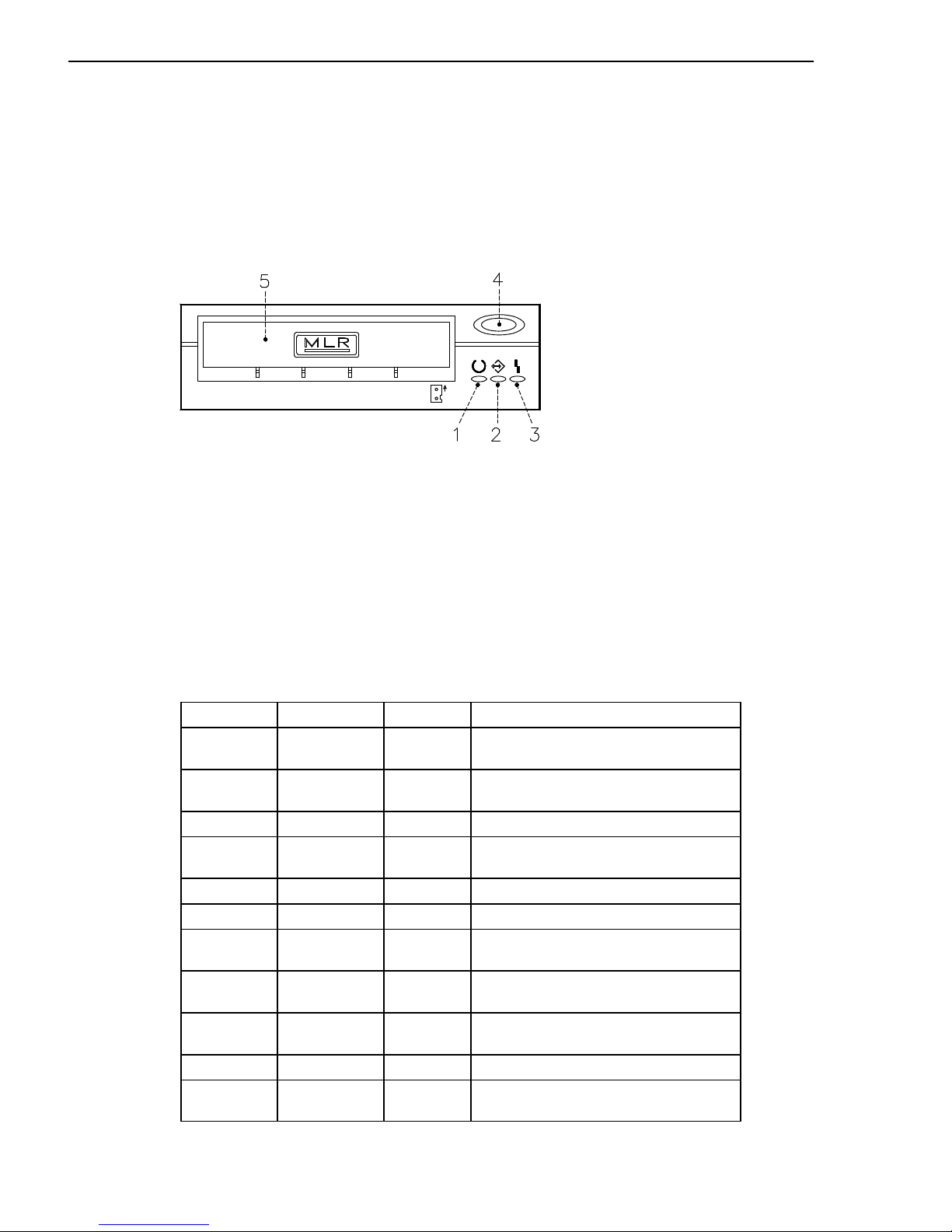
Functions
The MLR tape drive has two green status lights and one amber status light. The on/off
combinations of the status lights indicate the conditions of the MLR tape drive.
1
Ready LED (green)
2
Activity LED (green)
3
Error LED (amber)
4
Unload button
5
Drive door
Status Lights
The following table explains the meaning of the green and amber status lights.
Ready LED
Activity LED Error LED Drive State
On On On LED-test (2 sec. at Power-on).
The LED’s are turned on one-by-one
Flashing Off Off Power-up self-test or diagnostic
cartridge activity
Off Off Off Cartridge/tape not loaded
Off Off On Cartridge/tape not loaded,
cleaning required
On Off Off Tape loaded, no tape movement
On Flashing Off Tape loaded, tape movement
On Off On Tape loaded, no tape movement,
cleaning required
On Flashing On Tape loaded, tape movement,
cleaning required
On Flashing Off Tape loading or unloading, or
cartridge unloading
Off Flashing On Cleaning loaded tape
Off Off Flashing Unrecoverable drive failure, cartridge
failure or Microcode download failure
Page 49

3-7Using Devices and Tools
Loading the 1/4-Inch Tape Cartridge
Before loading the tape cartridge, make sure the power is on and the write-protect tab on
the tape cartridge is properly set. Refer to Setting the Write-Protect Tab
, below.
Note: For detailed information about the supported cartridges and their compatibility with
the different media drives, please refer to the Disks and Tapes Configuration
Information guide.
Once the cartridge has been inserted, it automatically rewinds to the beginning of the tape.
1. Grasp the edges of the MLR tape cartridge with the write-protect switch at your right side
and the window side of the cartridge facing up.
2. Slide the tape cartridge into the opening on the front of the MLR tape drive until the
loading mechanism pulls the cartridge into the drive and the drive door closes. The
Ready LED will light if the load operation was successful.
The tape takes few seconds to load. When the Ready LED lights, the drive is ready for data
operations.
Commands can be entered while the tape is loading. Any commands to the tape drive start
running once the tape has finished loading. Commands not requiring the tape cartridge will
run immediately.
Unloading the 1/4-Inch Tape Cartridge
Push the unload button. The drive will rewind the tape within the cartridge and eject the
cartridge from the drive opening.
The time required for a tape to rewind and unload depends on the position of the tape when
the unload button is pushed.
If the tape cartridge cannot unload and has to be removed manually from the drive, contact
your Service Representative.
Setting the Write-Protect Tab
Setting the write-protect tab on a tape cartridge is necessary so that information is not
accidentally lost. When the write-protect tab of a tape cartridge is set (pointing to SAFE or
locked padlock), information can be read from the tape but cannot be written to it.
Use a small screwdriver to turn the arrow to the desired position. The arrow must be
pointing to one of the two positions.
Page 50

3-8
Setup Guide
Handling MLR Tape Cartridges
Information in this paragraph describes operating and storage conditions including
temperature, relative humidity, and maximum wet bulb data.
Warning: The manufacturer has specified a set of temperature and humidity ranges in
which the 1/4-inch data cartridge can operate with ease. Only regular cleaning procedures
are required when operating the cartridge within this range. The risk of possible data loss is
increased if 1/4-inch tape cartridges are operated, stored, or shipped outside the
temperature or humidity ranges shown in the following table.
Before using a cartridge, always let it adjust (acclimate) to the operating environment. Do
this by placing the cartridge with its container in the operating environment for as long as it
has been away from this environment or for 24 hours, whichever is less.
Acclimation is necessary for any data cartridge that has been exposed to a different
humidity environment or a temperature change of 11°C (20°F), or more.
• Recommended Operating Environment:
– Temperature 5°C to 40°C (41°F to 104°F)
– Relative Humidity 20% to 80% non condensing
– Wet Bulb 26°C (79°F).
• Recommended Storage Environment:
– Temperature -30°C to 60°F (-22°F to 140°F)
– Relative Humidity 5% to 90% non condensing.
Cleaning the MLR Drive
Clean the recording head of the tape drive after the first 2 hours of tape movement when
you are using new tape cartridges. If you are using QIC-2GB, QIC-1000 cartridges and the
cartridges are not new, clean the recording head after every 8 hours of tape movement.
Use the instructions and materials provided in the cleaning kit to ensure proper operation of
the tape drive.
Warning: The drive must be cleaned with a dry process cleaning cartridge. The wet
cleaning cartridges used on old QIC models are prohibited and may damage the drive.
Tape Cartridge Data Efficiency
Note: For maximum efficiency, operate the 1/4-inch tape drive in the streaming mode
whenever possible.
The 1/4-inch tape cartridge efficiency is defined as the amount of data that can be stored on
the cartridge and the rate at which the data can be read from the tape cartridge. When in
use, the tape in the cartridge is moved at a constant speed of 72 inches per second. The
speed for the QIC-2GB is 70.9 inches per second.
The following variables affect the amount of data that can be stored on a tape cartridge:
• Streaming mode or non-streaming mode
• Size of the data file
• Number of file marks per file
• Tape length
• Size of post/preamble.
Page 51
3-9Using Devices and Tools
Using the 7/14GB 8 mm Tape Drive
The 7/14GB 8 mm tape drive, is a high capacity tape drive. It is typically used as backup drive.
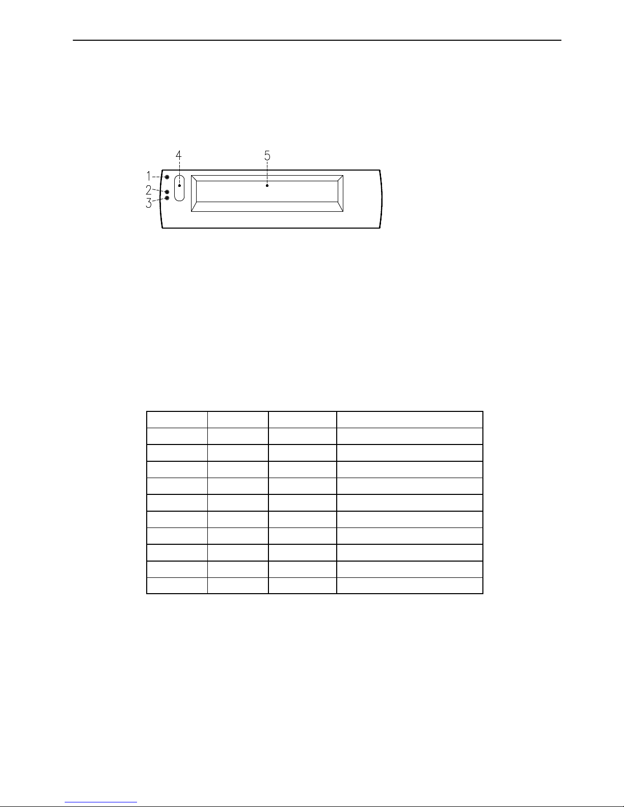
Functions
The 7/14GB 8 mm tape drive has one amber status light and two green status lights.
The on/off combinations of the status lights indicate the conditions of the 7/14GB 8 mm tape
drive.
1
Error LED (amber)
2
SCSI LED (green)
3
Motion LED (green)
4
Unload button
5
Drive door
Status Lights
The following table describes various LED combinations that occur during normal tape drive
operation.
Error LED
SCSI LED Motion LED Device State
On On On Power-On Self-Test is running
Flashing
(2)
Flashing
(1)
Off Failed Power-On Self-Test
Off Flashing
(1)
Off Ready (no tape loaded)
Off Flashing
(1)
On Ready (tape loaded)
Off Flashing
(1)
Flashing
(3)
Normal tape motion
Off Flashing
(1)
Flashing
(2)
High Speed tape motion
On Flashing
(1)
On SCSI Bus reset
Flashing
(3)
n/a Off Error
Flashing
(2)
n/a Flashing
(2)
Time to clean
Off Flashing
(1)
Flashing
(3)
Cleaning in progress
The LED is flashing:
(1) irregular
(2) fast = 4 flashes/second
(3) slow = 1 flash/second
Note: If a fault or an error condition occurs, first try to recover by pressing the unload
button. If the condition continues, call your Service Representative.
Page 52
3-10
Setup Guide
Loading the 8 mm Tape Cartridge
Before loading the tape cartridge, make sure the power is on and the write-protect tab on
the tape cartridge is properly set. Refer to Setting the Write-Protect Tab
, below.
Note: For detailed information about the supported cartridges and their compatibility with
the different media drives, please refer to the Disks and Tapes Configuration
Information guide.
1. Grasp the edges of the 8 mm tape cartridge with the write-protect switch towards you
and the window side of the cartridge facing up.
2. Slide the tape cartridge into the opening on the front of the tape drive until the loading
mechanism pulls the cartridge into the drive and the drive door closes. The Motion LED
will light if the load operation was successful.
The tape takes about 25 seconds to load. When the Motion LED lights, the drive is ready for
data operations.
Commands can be entered while the tape is loading. Any commands to the tape drive start
running once the tape has finished loading. Commands not requiring the tape cartridge will
run immediately.
Unloading the 8 mm Tape Cartridge
Push the unload button. The tape drive will rewind the tape within the cartridge and eject the
cartridge from the drive opening.
The time required for a tape to rewind and unload is between 18 seconds and 3 minutes,
depending on the position of the tape when the unload button is pushed.
If the tape cartridge cannot unload and has to be removed manually from the drive, contact
your Service Representative.
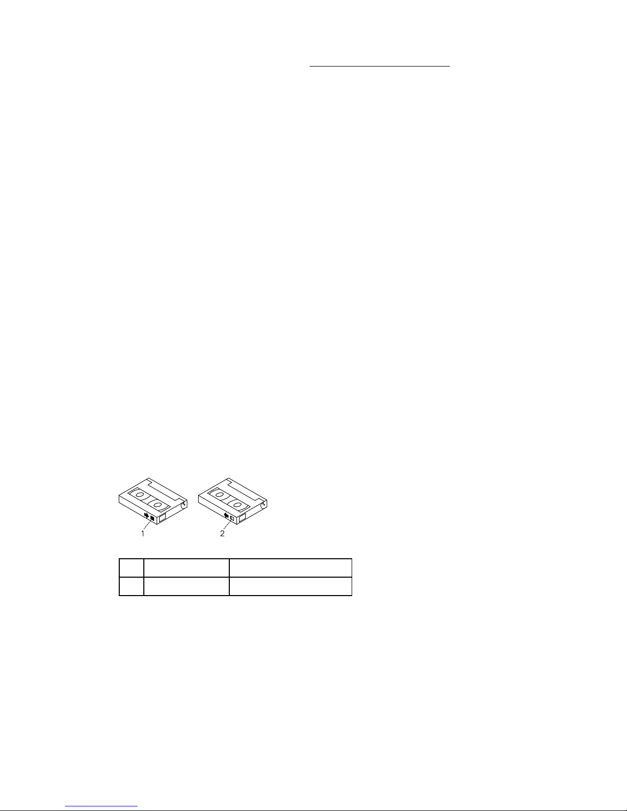
Setting the Write-Protect Tab
The window on the tape cartridge controls write-protection. When the write-protect tab of a
tape cartridge is set (window closed), information can be read from the tape, but cannot be
written to it. When the write-protect tab of a tape cartridge is not set (window open),
information can be both written to and read from the tape. Trying to write to a 8 mm data
cartridge with the window closed causes an error.
1
Window closed Write-protect tab set
2
Window open Write-protect tab not set
Page 53

3-11Using Devices and Tools
Handling 8 mm Tapes
When loading a tape in the drive, the cartridge should be removed from the case very close
to the front panel of the drive to minimize accumulation of air-born dust and dirt particles.
The same process should be followed when removing the tape from the drive.
Do not permit smoking near the tape drive, as smoke particles can cause data errors.
Do not use excessive force when inserting or removing the cartridge from the drive. If it
seems to hang up, gently repeat the load or unload process.
If the cartridge is placed inside a briefcase, and kept from moving around, it may be
possible to safely transport it through hostile environments.
The case should be carried directly to the storage area and not be exposed to long periods
of high or low temperatures.
It must never be left in a car window where sunshine can rapidly heat the air, and never left
in a car overnight.
It should be noted that airport-style metal detectors and hand held scanners will not affect
the data stored on the 8 mm tape.
• Recommended Operating Environment:
– Temperature 5°C to 40°C (41°F to 104°F)
– Relative Humidity 20% to 80% non condensing
– Wet Bulb to 26°C (79°F).
• Recommended Storage Environment:
– Temperature -40°C to 60°C (-40°F to 140°F)
– Relative Humidity 10% to 90% non condensing.
Note: Before using a data cartridge, allow it to acclimate to the operating environment (24
hours or the amount of time it has been exposed to dissimilar conditions).
Cleaning the Tape Path on the 8 mm Tape Drive
Warning: Do not use video cleaning cartridges in the tape drive. Video cleaning cartridges
can damage it. Some video cleaning cartridges are extremely abrasive. An tape drive may
be permanently damaged after only a few cleaning operations using an abrasive-type
cleaning cartridge.
When the tape drive requires cleaning, the Error and the Motion LED’s flash. You should
clean the tape drive as soon as possible after the LED’s begin flashing. Use the Exabyte
Premium 8 mm Cleaning Cartridge to clean your tape drive.
The 8 mm tape path should be cleaned either approximately every 30 hours of tape motion
or once a month.
More frequent cleaning may be required if the drive is operated in a dusty environment or in
humid conditions. If dust is allowed to accumulate, the drive has to perform more reads and
writes. That can cause a data loss. This can be prevented by regularly scheduled cleaning
of the drive.
The cleaning cartridge can clean the drive up to 18 times before being discarded. If you
attempt to use an 8 mm cleaning cartridge more than 18 times, the tape drive automatically
detects the error and ejects the cleaning cartridge with the disturbance status light
remaining on.
Before loading the 8 mm cleaning cartridge, make sure the power to the 8 mm tape drive is on.
Page 54

3-12
Setup Guide
Archive Life
If proper storage conditions are maintained, quality 8 mm tapes can have a recorded data
archive life of over 30 years:
• Use tapes with 4 to 20 passes on them. In the first few passes, new tapes shake off or
shed excess magnetic media and binder deposited during the tape manufacturing
process, these may result in higher soft error rates during the first few passes
• Pre-condition the tapes:
– Write/Read tape to measure error statistics (from BOT to EOT)
– Do this a minimum of 4 passes and a maximum of 20 passes
– Do this on a known good drive
– Physically examine the tape pack for correct winding
– Use only tapes that have been temperature stabilized.
• Maintain constant environment:
– Best environment is 18°C (65°F) at 40% RH
– Control environment while transporting tapes
– Ensure no chemical conditions exist
– No dust
– Have positive air pressure.
• Long Term Archiving Conditions:
– 5°C to 32°C (41°F to 90°F)
– Relative Humidity 20% to 60% non condensing
– Wet bulb 26°C (79°F) maximum.
• Local Archiving Conditions Range:
– 18°C to 40°C (65°F to 104°F)
– Relative Humidity 40% to 60% non condensing.
• Store on edge in their protective enclosures and do not stack anything on top of them
• Keep the drive clean
• Store data in a streaming (not Start/Stop) mode; run the tape from BOT to EOT at normal
speed
• Exercise the tapes once every 12 months by reading the entire tape, to remove any
stress which has built up in the tape pack during the storage interval; this interval can be
lessened at lower temperature conditions, and should be increased at higher temperature
conditions.
Page 55
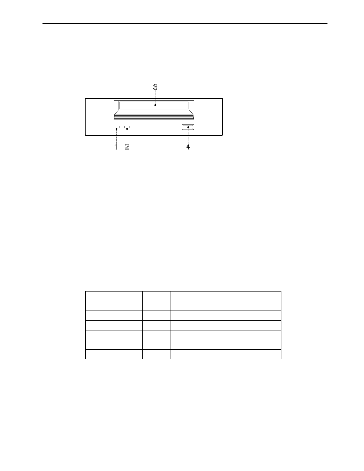
3-13Using Devices and Tools
Using the 4 mm Tape Drive
The 4 mm tape drive, is a high capacity tape drive. It is typically used as a backup drive.
Functions
The 4 mm tape drive has one green status light and one amber status light. The on/off
combinations of the status light indicate the conditions of the 4 mm tape drive.
1
Tape LED (green)
2
Clean/Attention LED (amber)
3
Drive door
4
Unload button
Status Lights
Tape LED (Green)
Flashes green to show activity (loading, unloading, reading and writing).
Steady green means a cartridge is loaded.
Clean/Attention LED (Amber)
Flashes amber to indicate head cleaning is needed or a cartridge is near the end of its life.
Steady amber indicates a serious fault.
The following table explains the meaning of the green and amber status lights.
Green
Amber Status
Flashing Off Load or unload
Fast Flashing Off Read or write
On Off Cartridge loaded
On, Off, or Flashing Flashing Cleaning needed signal
On, Off, or Flashing On Fault
Flashing Off Power-on (starts with two steady lights)
Page 56
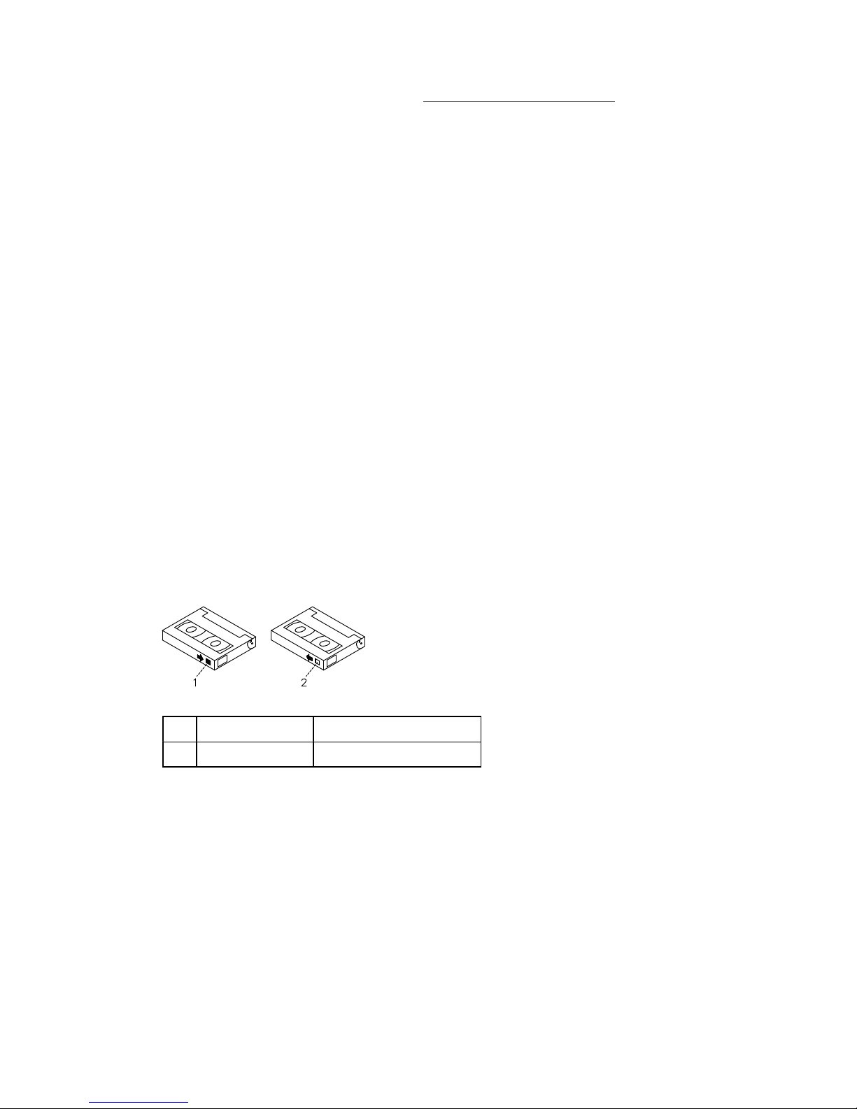
3-14
Setup Guide
Loading the 4 mm Tape Cartridge
Before loading the tape cartridge, make sure the power is on and the write-protect tab on
the tape cartridge is properly set. Refer to Setting the Write-Protect Tab
, below.
Note: For detailed information about the supported cartridges and their compatibility with
the different media drives, please refer to the Disks and Tapes Configuration
Information guide.
To load the 4 mm tape cartridge, do the following:
1. Grasp the edges of the 4 mm tape cartridge with the write-protect tab towards you and
the window side of the cartridge facing up.
2. Slide the tape cartridge into the opening on the front of the 4 mm drive until the loading
mechanism pulls the cartridge into the drive and the drive door closes.
The 4 mm tape drive is ready for data operations when the tape cartridge is inserted. After
the cartridge is inserted into the tape drive, the tape takes about 15 seconds to load.
Unloading the 4 mm Tape Cartridge
Before performing the unload operation, make sure the power to the 4 mm tape drive is on.
To unload and eject the tape cartridge, press the unload button. The 4 mm tape drive
rewinds the tape and then ejects the tape cartridge from the tape drive.
The time required for a tape to rewind and unload is between 10 seconds and 1.5 minutes,
depending on the position of the tape when the unload button is pushed.
Setting the Write-Protect Tab
The window on the tape cartridge controls write-protection. When the write-protect tab of a
tape cartridge is set (window open), information can be read from the tape, but cannot be
written to it. When the write-protect tab of a tape cartridge is not set (window closed),
information can be both written to and read from the tape. Trying to write to a 4 mm data
cartridge with the window open causes an error.
1
Window closed Write-protect tab not set
2
Window open Write-protect tab set
Page 57

3-15Using Devices and Tools
Handling 4 mm Tapes
Information in this section describes operating and storage conditions including
temperature, relative humidity, and maximum wet bulb data.
Warning: The manufacturer has specified a set of temperature and humidity ranges in
which the 4 mm data cartridge can operate with ease. Only regular cleaning procedures, as
described in Cleaning the Tape Path on the 4 mm Tape Drive
, on page 3-16, are required
when operating the cartridge within this range. The risk of possible data loss is increased if
4 mm tape cartridges are operated, stored, or shipped outside the temperature or humidity
ranges shown below.
Before using a cartridge, always let it adjust (acclimate) to the operating environment. Do
this by placing the cartridge with its container in the operating environment for as long as it
has been away from this environment or for 24 hours, whichever is less.
Acclimation is necessary for any data cartridge that has been exposed to a different
humidity environment or a temperature change of 11°C (20°F), or more.
• Recommended Operating Environment:
– Temperature 16°C to 32°C (60°F to 90°F)
– Relative Humidity 20% to 80% non condensing
– Wet Bulb to 26°C (79°F).
• Recommended Storage Environment:
– Temperature 5°C to 32°C (40°F to 90°F)
– Relative Humidity 20% to 80% non condensing.
Operating in Harsh Environments
The 4 mm tape drive is ideally suited to streaming operations, as opposed to tape
movement operations involving multiple stop/starts and random searches. When the tape is
used for frequent stop and start operations, streaming movement is beneficial and should
be used whenever possible. This can be accomplished by ensuring that any save or restore
operation is the only active operation performed by a device connected to this SCSI I/O
controller.
Any tape that has been used outside the ranges specified in the previous table for an
extended period of time (50 passes in 40 hours of nonstop operation) should not be used as
an archival tape. Exposure to the environment will deteriorate the magnetic and physical
strength of the tape. Do not store important data on a tape that has been used outside the
specified ranges; transfer the data to a new tape for reliable archiving.
Page 58

3-16
Setup Guide
Cleaning the Tape Path on the 4 mm Tape Drive
The 4 mm tape path should be cleaned either approximately every 30 hours of tape motion
or once a month, whichever occurs first. The 4 mm tape drive monitors the recording quality
of the tape cartridge and indicates that the tape path requires cleaning when the
clean/attention light (amber) is flashing, see page 3-13.
More frequent cleaning may be required if the drive is operated in a dusty environment or in
humid conditions. If the dust is allowed to accumulate, the drive has to perform more reads
and writes which can cause data loss. This can be prevented by regularly scheduled
cleaning of the drive.
The cleaning cartridge can clean the 4 mm tape drive 50 times before it needs to be
discarded. If you attempt to use a 4 mm cleaning cartridge more than 50 times, the tape
drive automatically detects the error and ejects the cleaning cartridge with the
clean/attention light (amber) remaining on, see page 3-13.
Before loading the cleaning cartridge, make sure the power to the 4 mm tape drive is on.
To load the 4 mm cleaning cartridge, do the following:
1. Grasp the edges of the 4 mm cleaning cartridge with the window side of the cartridge
facing up.
2. Slide the cleaning cartridge into the opening on the front of the 4 mm tape drive until the
loading mechanism pulls the cartridge into the drive.
After the 4 mm cleaning cartridge has been fully inserted into the 4 mm tape drive, the
following cleaning operations are performed automatically:
1. The cleaning tape is loaded into the tape path.
2. The drive is cleaned by moving the cleaning tape forward for approximately 30 seconds.
3. The tape is unloaded and the cleaning cartridge is ejected from the tape drive when the
cleaning operation is complete.
4. A successful cleaning operation is indicated when the clean/attention light (amber) goes
off, see page 3-13 (if it was activated before the cleaning operation).
Page 59
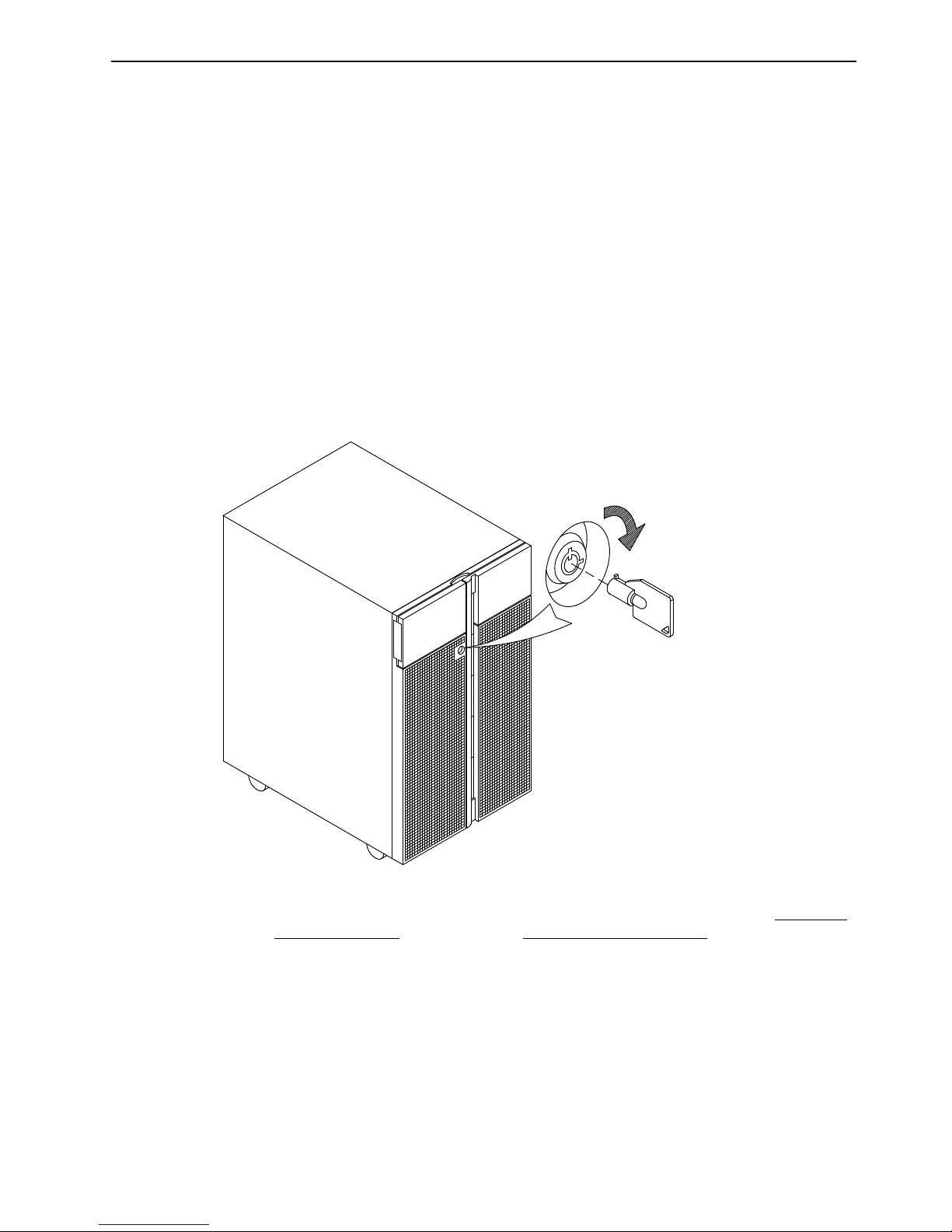
3-17Using Devices and Tools
Using Hard Disk Drives
The hard disk drives are located in the device area on the right side of the unit front.
The working status of each hard disk drive installed on your system is given through two
LED’s (blue/green and amber lights) that are visible looking at the front of the system unit.
The meaning of the LED status depends on your disk configuration. If the disk belongs to a
RAID array, the amber LED light on and steady indicates a fault condition, the blue/green
LED light indicates disk activity.
If the disk does not belong to a RAID array, the amber LED is not meaningful and the
blue/green LED indicates if the disk is powered on (blue/green LED light on and steady) or
is powered off (blue/green LED light off).
Notes:
1. The blue LED color means: ULTRA-2/LVD mode.
2. The green LED color means: ULTRA/SE mode.
Open the device shutter by turning the device shutter key to the right, to access the hard
disks.
Note: If you need to install or remove the disk devices, refer respectively to Hard Disk
Drive Installation, on page 6-23 or Hard Disk Drive Removal, on page 6-30.
Page 60
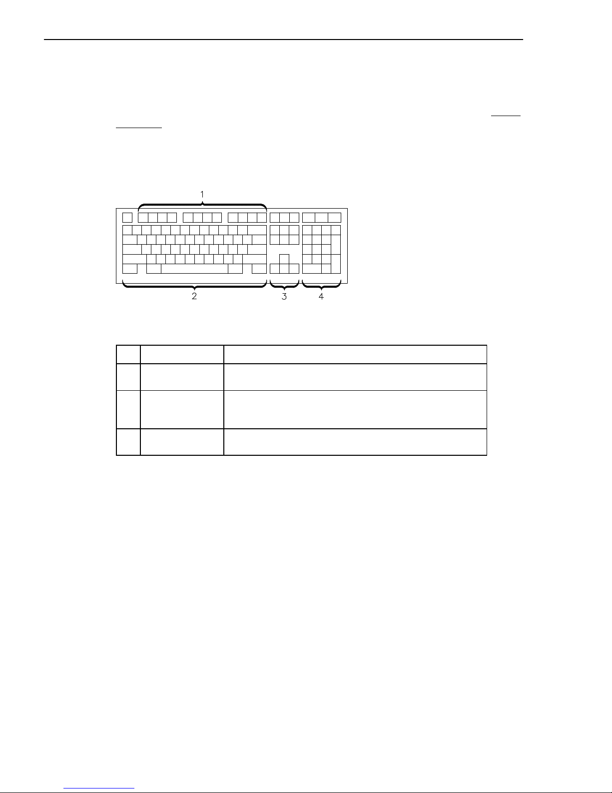
3-18
Setup Guide
Using the Keyboard
There are several keyboards available with the system unit. The keyboards have various
keys that enter data and control the cursor location.
The keyboards can be engraved for the languages of different countries. National languages
can be set through the Open Firmware menu. For further information, please refer to Select
Keyboard, on page 4-11.
The functions of each keyboard depend on the software used. The character sets for the
keyboards are explained in your operating system documentation.
The keyboard is divided into four sections:
1
Function keys Multipurpose keys controlled by the operating system
2
Typewriter keys Similar to those of a standard typewriter. Their function is
controlled by the software
3
Control keys Move the cursor on the screen and do programmed
control functions. The movement and functions depend
upon the used application
4
Numeric keypad A keypad arranged like a calculator to help when typing
numbers
On all of the keyboards, you can adjust the tilt position for typing comfort. To tilt the
keyboard, pull out the keyboard legs. The legs will snap into position. To decrease the tilt of
the keyboard, rotate the keyboard legs until they snap into the bottom of the keyboard case.
Note: The keyboard plugged into the connector at the rear of the base unit, can be used
only with the system graphic monitor.
Page 61

3-19Using Devices and Tools
Using the Mouse
The mouse is a hand-operated locating device. A two or three button mouse is available for
use with the system unit.
Consult your application publication for the exact use of the mouse.
You can use the mouse to perform such functions as positioning a cursor, selecting items
from a menu, or moving around in your document much easier and faster than if you used
only the keyboard. The cursor moves exactly as you move the mouse on a flat surface,
such as a desktop.
When you move the mouse around on a flat surface the cursor moves on the display
screen; the movement changes the position of the cursor.
With the mouse buttons, you can perform functions such as selecting and deselecting
options, extending your selection, or choosing a command. The precise functioning of your
mouse depends on the software you are using.
Note: The mouse plugged into the connector at the rear of the base unit, can be used only
with the system graphic monitor.
Page 62

3-20
Setup Guide
Handling the Mouse
For best operation, handle the mouse with care. Incorrect handling can damage the mouse.
• Do not operate the mouse on cloth, unfinished wood, newspaper, or carpet
• Do not drop or hit the mouse
• Do not carry the mouse by holding onto the cable
• Do not expose the mouse to extreme temperatures or direct sunlight
• Do not place the mouse in liquid spills.
Cleaning the Mouse
1. Remove the retaining ring by turning it counterclockwise, in the direction of the arrow.
2. Remove the ball.
3. Inspect the ball for contaminants. Wipe it clean with a dry, lint-free cloth.
4. If the ball is dirty, wash it in warm, soapy water. Rinse and wipe the ball with a lint-free
cloth until dry.
5. Inspect the ball cavity in the mouse for foreign materials. If there are any foreign
materials, remove them.
6. Replace the ball.
7. Replace the retaining ring on the mouse and align it with the open slots in the ball cavity.
8. Turn the retaining ring clockwise until the open slots are covered and you hear the ring
snap into place.
Care of the Mouse
The operating surface for the mouse should be smooth, clean, and flat. For example, you
can operate the mouse on the following surfaces:
• Finished wood
• Glass
• Enamel
• Plastic
• Paper (except newspaper)
• Metal.
Rough surfaces collect contaminants that can be transferred to the interior of the mouse by
the ball. The surface you use should be free from spills, dirt, dust, lint, wax, eraser dust, and
other foreign matter. Rough surfaces can also cause the pads located on the bottom of the
mouse to prematurely wear. A deeply pitted surface could cause erratic operation of the
mouse.
• Inspect the work surface for spills or other contaminants
• Dust the work surface
• If you are using a paper pad, inspect it for wear and replace it if necessary.
Page 63

Maintaining the System 4-1
Chapter 4. Maintaining the System
• Starting and Stopping the System
, below
• Maintaining System Configuration Variables
, on page 4-4
• Problem Solving
, on page 4-16.
Starting and Stopping the System
This section describes the steps for the power on and power off procedures for normal
operation of your system.
• Starting the System
, below
• Logging into the System
, on page 4-2
• Stopping the System
, on page 4-2
• Rebooting the System
, on page 4-3.
Starting the System
CAUTION:
For proper cooling and safe operation of the computer, all the covers must be in
place before you power up the system.
Follow these steps to power up the system for your daily operation.
1. If a disk expansion unit is connected, be sure that its key mode switch is properly set.
For detailed information, please refer to the Using the Disk Expansion Unit guide.
2. Be sure that the system unit, all external devices and expansion units (if any), are
connected to the proper power outlets.
3. Switch on the external devices (if connected).
4. Switch on the system console.
5. Power on the system setting the base unit key mode switch to the Normal position.
6. The system begins its normal startup routine and is ready for use.
7. You can now log into the system.
Note: In case you power on the system by setting the key mode switch to the Service
position, you enter the operating system diagnostic mode.
Page 64

4-2 Setup Guide
Logging into the System
Warning: After you have started the system, it may take a few minutes for the login prompt
to appear on the display. This amount of time depends on your system configuration. Do not
press any keys while you are waiting, as this may cause unexpected results.
When the login prompt appears on the display:
1. Type your login name and press the Enter key or click on the OK button.
2. If a password is required (the related prompt appears), type your password and press
the Enter key or click on the OK button (the screen does not display your password as
you type it).
If the password prompt does not appear, you have no password defined and you can
begin working on the operating system.
If the system displays:
login incorrect
Log in again, and enter the correct login name and password. If you still have problems,
ask your system administrator.
Stopping the System
Warning: When using the shutdown procedure for your system, enter the correct command
before you stop the system. Failure to do so, may result in loss of data. Please refer to your
operating system documentation.
1. Exit any applications that are running. Consult the applications manuals for instructions.
2. Ensure that the media drives do not contain any media.
3. Exit the operating system using the appropriate shutdown command.
a. It is possible to execute the shutdown procedure from the system console (local or
remote line) with the base unit key set to the Secure position. Remember, before
rebooting the system, to set the base unit key mode switch to the Normal or the
Service position.
b. When the shutdown program is executed, a warning message is sent to all
connected terminals. You can specify the time period between the sending of the
warning message and the system shutdown.
Here is an example:
shutdown –h +5r
represents a period of 5 minutes.
Warning: This period should allow all the users sufficient time to finish their sessions
and save their data. The amount of time can vary from a few seconds (allowing the
user to exit the vi editor, for example) to several minutes (allowing the user to
properly finish the update of a database). In the case of a user updating a database,
if the system is shutdown before the user has properly finished his update session,
there can be loss of important data.
4. Set the base unit key mode switch to the Power Off position.
Note: If nobody needs to use the system, remove the key, to prevent unauthorized reset of
the system.
Page 65

Maintaining the System 4-3
Rebooting the System
A system reboot recopies the operating system from disk to memory and starts it without
turning the system completely off. Reboot is also known as a system reset. It reinitializes
the operating system by repeating the Initial Program Load (IPL) operation.
The reboot command synchronizes the hard disks and performs some other shutdown
activities without halting the system. Use the reboot command to reboot the operating
system when it is accessed by only one user. The shutdown command is used instead of
the reboot command when the system is running and multiple users are logged on.
Reboot to cause the system to recognize newly installed software, to reset peripheral
devices or to recover from a system crash.
To reboot the system you must have root user authority.
At the prompt, enter:
reboot
The system reboots.
Page 66

4-4 Setup Guide
Maintaining System Configuration Variables
The system configuration variables can be displayed and modified in a controlled and
interactive mode, through the user interface provided by the Open Firmware menu.
The Open Firmware features can be used during the system power on phase to display and
modify system configuration variables, perform maintenance operations, boot or reset the
system. An interactive command interpreter is also available, for very specialistic
maintenance tasks.
• What is Open Firmware, below
• How to Access Open Firmware
, below
• Display and Description of the Open Firmware Menu
, on page 4-5.
What is Open Firmware
Open Firmware is an open-standard boot firmware that can be used on different hardware
configurations. The Open Firmware architecture is designed to bring standardization of the
firmware area providing a resilient framework, growing and evolving with new technologies.
The Open Firmware main function is to initialize the hardware and then load and execute
the operating system. Additional functions are the hardware testing and the management of
hardware configuration information.
Open Firmware is defined by the IEEE Standard 1275-1994, Standard for Boot Firmware.
How to Access Open Firmware
The Open Firmware features are mainly addressed to people trained to perform service
tasks on the system. The user should have a good knowledge of the system architecture
and hardware design.
The Open Firmware features can be accessed through a menu, in a controlled and
interactive mode, on:
• A graphic terminal connected to the SVGA port (default Open Firmware console), or
• A terminal connected to the COM1 port (BUMP console).
The menu is available in English only.
The access to the Open Firmware menu is conditioned by the Open Firmware auto-boot?
variable, by default true (the system boots automatically).
The Open Firmware menu is called:
• Typing any key before completion of boot image loading, or
• Configuring the auto-boot? variable = false; for more information, see Boot options
, on
page 4-9.
Page 67

Maintaining the System 4-5
Display and Description of the Open Firmware Menu
The Open Firmware menu allows to view hardware configuration, display and modify
system configuration variables, such as boot options and device alias definition, boot or
reset the system, set remote maintenance variables.
The Open Firmware variables are stored in non-volatile memory (NVRAM). In case NVRAM
is corrupted, the configuration variables are automatically restored to their default values.
A whole list of Open Firmware configuration variables is available in the Maintenance Guide.
Notes:
1. The modifications applied to the configuration variables do not take effect until a
system restart.
2. The configuration variables must be modified with care to avoid compromising the
system’s behavior.
3. The menu screens shown in this section are those displayed on the graphic
console. The variable values are shown as example.
The menu is entered with the following main screen.
System Menu
- System Configuration
- Boot Operating System
- Reset Machine
- System Maintenance
- Help
Operating Procedures
The following operating procedures are common to all screens in the menu tree:
• From the graphic console:
– Use the arrows or Tab key or mouse click to move inside the screen
– Use the Enter key or mouse click to select an item
– Use the OK button to confirm the modification(s) or the Cancel button to cancel the
operation.
• From the BUMP console:
– Enter the number identifying one item to select it
– Press the Enter key to confirm the selection.
Page 68
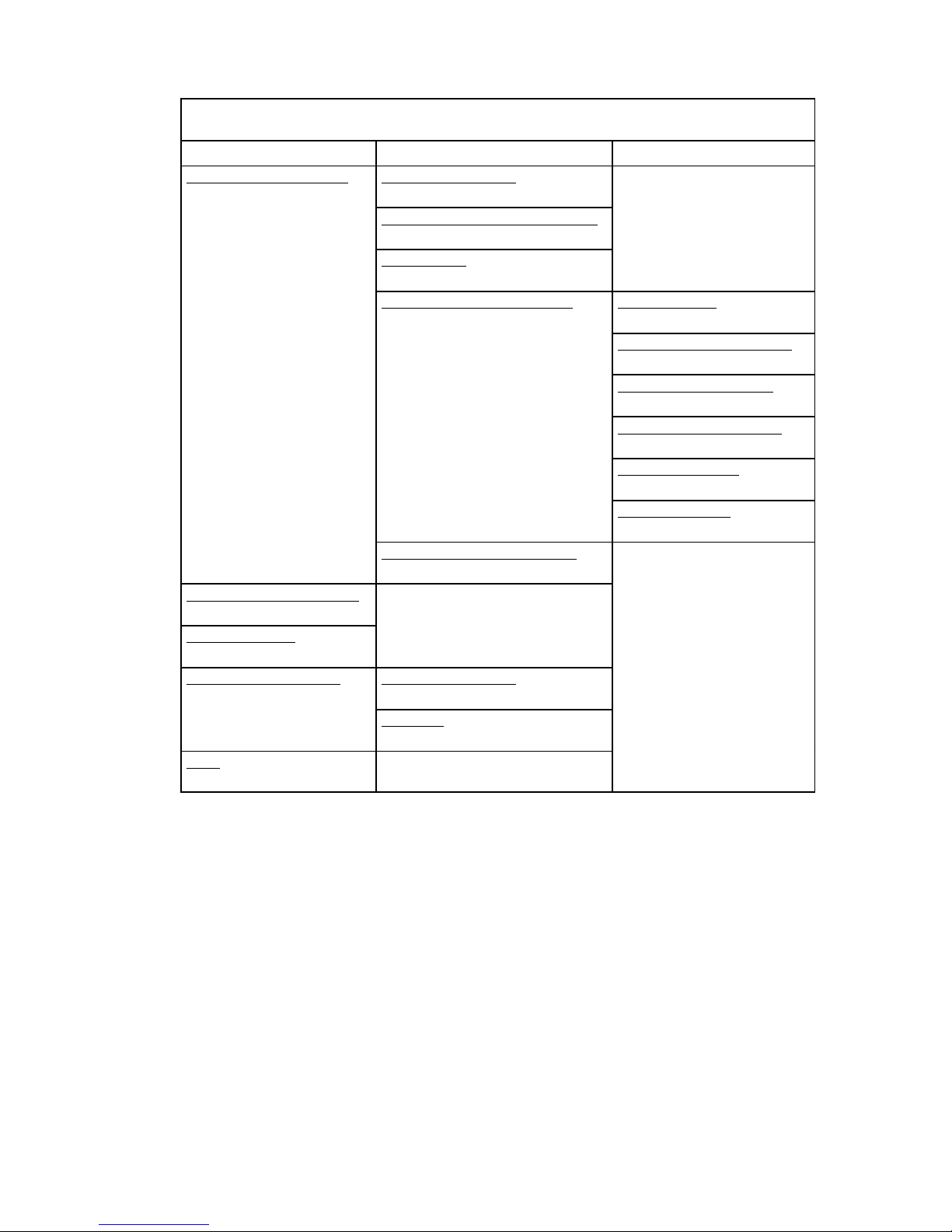
4-6 Setup Guide
The following table summarizes the Open Firmware menu available features, providing the
page reference for a quick search.
OPEN FIRMWARE SYSTEM MENU
Available Features
Main Screen, First Level Second Level Third Level
System Configuration,
on page 4-7
Set Date and Time,
on page 4-7
View Hardware Configuration,
on page 4-8
Probe SCSI,
on page 4-8
Manage NVRAM Variables,
on page 4-8
Boot Options,
on page 4-9
Configuration Variables,
on page 4-9
Remote Maintenance,
on page 4-10
Surveillance Variables,
on page 4-11
Select Keyboard,
on page 4-11
Alias Definition,
on page 4-12
Manage Operating System,
on page 4-13
Boot Operating System,
on page 4-14
Reset Machine,
on page 4-14
System Maintenance,
on page 4-14
Change Password,
on page 4-15
ok Forth,
on page 4-15
Help,
on page 4-15
Page 69
Maintaining the System 4-7
The following paragraphs describe in detail the Open Firmware menu options.
System Configuration
System Menu
- System Configuration
Select SYSTEM CONFIGURATION and the following screen is displayed.
System Configuration
- Set Date and Time
- View Hardware Configuration
- Probe SCSI
- Manage NVRAM Variables
- Manage Operating System
- Return to System Menu
- Help
Set Date and Time
System Menu
- System Configuration
- Set Date and Time
Select SET DATE AND TIME to display and/or update the date and time of the system. To
update, position on the specific field and edit it accordingly. The date is set according to
UTC (Universal Time Coordinated) format. The following screen is displayed.
Set Date and Time
Date: xx - xx - xxxx
mm - dd - yyyy
Time: xx - xx - xx
hh : mm : ss
CancelOK
Page 70
4-8 Setup Guide
View Hardware Configuration
System Menu
- System Configuration
- View Hardware Configuration
Select VIEW HARDWARE CONFIGURATION to display the system device tree. Each
device is identified by a unique name representing the type of device and where the device
is located within the system device tree.
The device path name consists of a series of node names separated by slashes ( / ). The
following example shows a full device path name: /pci@fe0f0020/scsi@2/disk@0,0.
The device path names can also be represented by device alias names. For more
information, refer to Alias Definition
, on page 4-12.
Probe SCSI
System Menu
- System Configuration
- Probe SCSI
Select PROBE SCSI to list the devices connected to all the SCSI busses installed in the
system.
Manage NVRAM Variables
System Menu
- System Configuration
- Manage NVRAM Variables
Select MANAGE NVRAM VARIABLES to display and/or update the common user Open
Firmware variables stored in NVRAM. The following screen is displayed.
Manage NVRAM Variables
- Boot options
- Configuration variables
- Remote maintenance
- Surveillance variables
- Select keyboard
- Alias definition
- Return to System Configuration
- Help
Page 71
Maintaining the System 4-9
Select BOOT OPTIONS to display and/or modify the system boot options. The following
screen is displayed.
System Menu
- System Configuration
- Manage NVRAM Variables
- Boot Options
Manage NVRAM Variables
Boot options:
auto-boot? true
boot-device cdrom# aixtape disk net
diag-switch? false
diag-device cdrom# aixtape disk net
CancelOK
The available boot options are:
• auto-boot?, determines the system boot phase:
– true, an automatic system boot is performed after power on or reset, else
– false, the Open Firmware menu is called.
• boot-device, identifies the device(s) from which the system boots normally
• diag-switch?, assumes the value of the system key mode switch position:
– false, if the key is set to the Normal position, and the system boots from the device
defined by boot-device, else
– true, if the key is set to the Service position, and the system boots from the device
defined by diag-device.
• diag-device, identifies the device(s) from which the system boots in diagnostic mode for
maintenance purposes.
Select CONFIGURATION VARIABLES to display and/or modify the parameters of the
configuration variables. The following screen is displayed.
System Menu
- System Configuration
- Manage NVRAM Variables
- Configuration Variables
Page 72
4-10 Setup Guide
Manage NVRAM Variables
Configuration variables:
input-device keyboard
output-device screen
pci0b-probe-list 8,9,a,b,c
pci0a-probe-list 2,3,4,5,6,7
CancelOK
The configuration variables are:
• input-device, identifies the console input device (usually keyboard for graphic terminal,
com1 for ASCII terminal (BUMP console) or com2)
• output-device, identifies the console output device (usually screen for graphic terminal,
com1 for ASCII terminal (BUMP console) or com2)
• pci0a-probe-list and pci0b-probe-list, list which PCI bus device numbers to probe and
in what order (the assumed value is system dependent and includes all available slots).
Select REMOTE MAINTENANCE to properly configure the remote maintenance flags. The
following screen is displayed.
System Menu
- System Configuration
- Manage NVRAM Variables
- Remote Maintenance
Manage NVRAM Variables
Remote maintenance:
sp-d-in? true
sp-d-out? false
sp-line 2
CancelOK
The remote maintenance flags are:
• sp-d-in, set to true gives remote maintenance authorization
• sp-d-out, set to true sends an automatic notification to the Service Center, in case of
failure at system power on
• sp-line, identifies the service line on which the remote connection will be established.
For more information about remote maintenance flags, please refer to the Maintenance
Guide.
Page 73
Maintaining the System 4-11
Select SURVEILLANCE VARIABLES to display and/or modify the state of surveillance
during the system runtime phase. The following screen is displayed.
System Menu
- System Configuration
- Manage NVRAM Variables
- Surveillance variables
Manage NVRAM Variables
Surveillance variables:
sp-sen off
sp-sti 5
sp-sdel 10
CancelOK
The surveillance variables are:
• sp-sen, defines the state of surveillance (on = enabled).
If sp-sen=on:
• sp-sti, defines the period of time of the periodic surveillance when the system control is
under the operating system. The time unit is minutes.
• sp-sdel, defines the period of time that the BUMP has to wait before starting the periodic
surveillance when the system control is under the operating system. This value covers
the AIX boot time. The time unit is minutes.
Select SELECT KEYBOARD to adopt the more suitable keyboard language (support of
different character set). The following screen is displayed.
System Menu
- System Configuration
- Manage NVRAM Variables
- Select Keyboard
Manage NVRAM Variables
Select keyboard:
US French UK
Italian German Spanish
Danish Finnish Norwegian
Belgian Portuguese
Selected: US
CancelOK
Page 74

4-12 Setup Guide
Select ALIAS DEFINITION to list, create and/or delete a device alias. A device alias is the
short representation of a device path. The most common used devices in the system have a
predefined alias name. The following screen is displayed.
System Menu
- System Configuration
- Manage NVRAM Variables
- Alias Definition
Manage NVRAM Variables
Select Alias definition:
- List
- New alias
- Delete alias
- Network boot alias
Select LIST, to list all current device aliases.
Select NEW ALIAS, to create a new alias definition. The alias name and device name are
requested.
Select DELETE ALIAS, to delete a defined device alias.
Select NETWORK BOOT ALIAS, to create or modify a network-boot alias. The following
details are requested:
• Alias name, alias name definition (by default, the alias net definition is displayed)
• Device name, the name of the network device (by default, the device path-name of
alias name is displayed)
• Server IPAddr, the IP address of the server system, where the boot file resides
• boot-file, the path-name of the boot file to be loaded from the server system (i.e.
/tftpboot/boot-file)
• Client IPAddr, the IP address of the client system
• GatewayIPAddr, the IP address of the gateway
• Netmask, the IP netmask of the host system.
Page 75
Maintaining the System 4-13
Manage Operating System
Select MANAGE OPERATING SYSTEM to display the first available boot device and/or
select a different boot device. The following screen is displayed.
System Menu
- System Configuration
- Manage Operating System
Manage Operating System
Select the device to boot:
/pci@fe0f0090/ethernet@8
CancelOK
DefaultBoot
To select a different boot device, position on the device path displayed and edit it
accordingly. The list of the present devices is shown through the View Hardware
Configuration menu option, on page 4-8.
Select OK, to modify the boot device variable permanently.
Select CANCEL, to cancel the operation.
Select BOOT, to perform an immediate system boot from the defined boot device.
The default value is automatically restored at the next system power on.
Note: The system boot could be conditioned by the security level defined by the system
administrator. A password could be requested. For more information, please refer to
the Maintenance Guide.
Select DEFAULT, to restore the value of the first available default boot device.
Page 76
4-14 Setup Guide
Boot Operating System
System Menu
- Boot Operating System
Select BOOT OPERATING SYSTEM to launch a system boot from the first available default
device.
Note: This option could be conditioned by the security level defined by the system
administrator. A password could be requested. For more information, please refer to
the Maintenance Guide.
Reset Machine
System Menu
- Reset Machine
Select RESET MACHINE to perform a system reset.
System Maintenance
System Menu
- System Maintenance
This option is reserved to the personnel who has a good knowledge of the system
architecture and hardware design.
Select SYSTEM MAINTENANCE and, for security reasons, a password is requested. For
more information, please refer to the Maintenance Guide.
Please enter the password: **************
CancelOK
If the password is entered correctly, the screen of this option is displayed.
System Maintenance
- Change Password
- OK Forth
- Return to System Manager Menu
- Help
Page 77
Maintaining the System 4-15
Change Password
System Menu
- System Maintenance
- Change Password
Select CHANGE PASSWORD to modify the security password configuration variable. The
following screen is displayed.
Update password:
Current Password: **************
New Password: **************
Confirm New Password: **************
CancelOK
Warning: If the password is forgotten, and the security level defined by the system
administrator, is set to a value other than none, the user is locked out of the system. A
Service Personnel intervention is required.
OK Forth
System Menu
- System Maintenance
- OK Forth
Warning: This option must be used by people having a deep knowledge of the Open
Firmware based language interpreter (Forth).
Select OK FORTH to access the Open Firmware command interpreter (ok prompt). The
following sentence is displayed.
Type ’menu’ to return to the menu ...
ok
The ok prompt command line gives you access to an extensive set of functions for
hardware and software development, fault isolation and debugging based on Forth
language interpreter. The commands that are available at ok prompt depend upon the
setting of security level defined by the system administrator. For more details, please refer
to the Maintenance Guide.
The main and most useful commands available through the interactive command interpreter
(ok prompt) are described in the Maintenance Guide.
Help
This option provides information about the current menu screen and the relevant operating
procedures.
Page 78

4-16 Setup Guide
Problem Solving
In case of system problems, you can consult What To Do When a Problem Occurs
, on
page 4-18.
If you decide to ask for assistance from your Service Representative, note that the following
information might be required:
• Any message displayed on the operator panel display
• Any message displayed on the system console
• Description of the symptoms
• Your system serial number.
Remember to record this information before calling.
Page 79
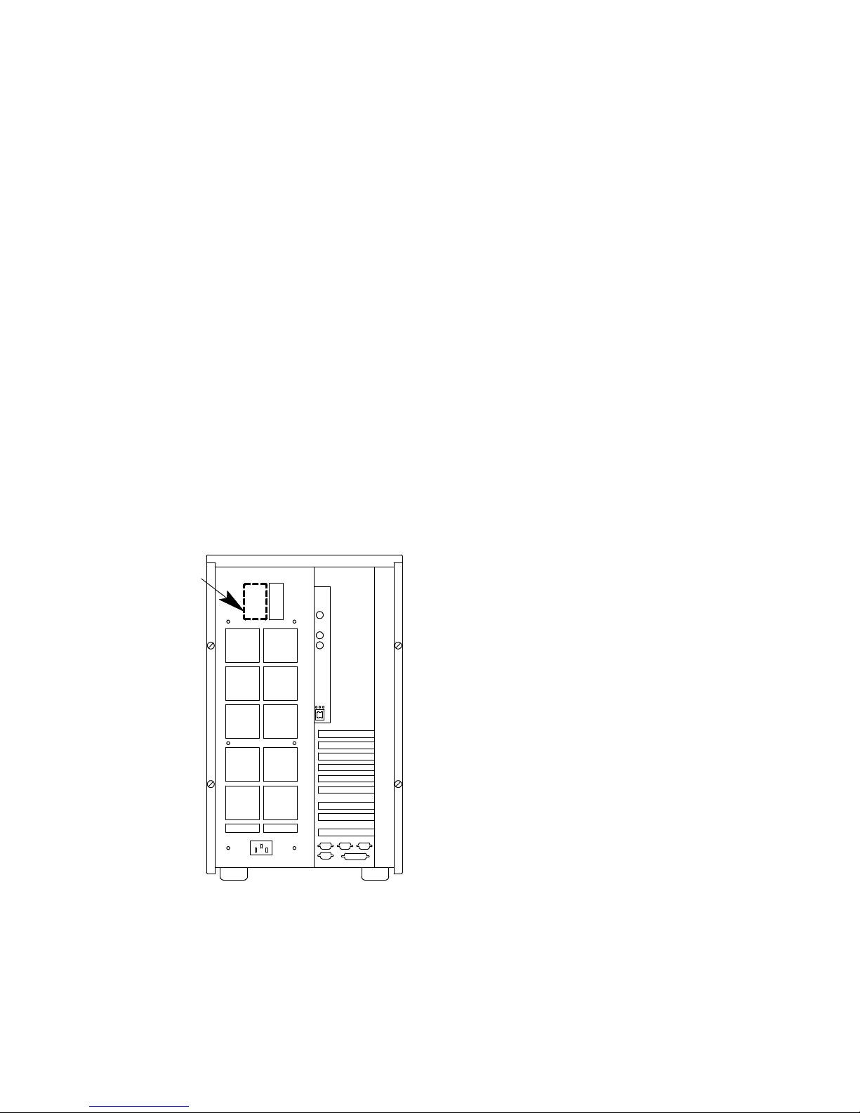
Maintaining the System 4-17
Identifying the Problem
It may happen, sometimes, that a problem prevents the system from working correctly.
In many cases, this depends on trivial causes, simple human faults, which can be easily
discovered and removed, with no need for a specialist intervention.
In other cases, bad functioning is due to more serious human faults or to a system failure,
and the problem solution requires technical intervention.
This chapter describes some common problems, the possible trivial causes and the related
solutions.
Only when you have ensured that the problem is not due to any of the listed causes, you
need technical intervention.
The system itself offers some maintenance tools, available also when the operating system
is not running, which test the system hardware, and perform the fault isolation.
If you are maintaining the system on your own, you can find the description of these tools in
the Maintenance Guide. This guide is available at your supplier.
The following paragraphs list some of the problems that may occur working with the
system, during either the system power on or its normal operating state. If you encounter
one of these problems, you can try to solve it on your own.
Otherwise, if it is necessary to call the technical support for assistance, remember to read
the system serial number, as this will be requested by the technical support.
The system serial number is written on the rating plate label placed on the rear side of the
unit, as shown in the figure.
Its format is XAN - Fxx - nnnnn, where:
Fxx is the system run code defined by the manufacturer
nnnnn is the system serial number (5 digits).
Note: XAN changes into XBH for the systems shipped to Brazil.
Page 80
4-18 Setup Guide
What To Do When a Problem Occurs
Problem Description
Possible Cause Solution
System Power
The system does not power
on
The system power cord is not
connected to an AC outlet.
Connect the power cord to a working AC
outlet.
The system power cord is not
properly connected.
Properly connect the power cord to the
system unit and to the AC outlet.
The AC outlet is faulty. Try another AC outlet.
The AC source is missing. Call your electrician to check the AC source.
Monitor
The monitor does not power
on (the monitor power light
The monitor power switch is not set
to the ON position.
Set the switch to the ON (I) position.
is off)
The power cord is not connected to
an AC outlet.
Connect the power cord to a working AC
outlet.
The power cord is not properly
connected.
Properly connect the power cord to the
monitor and to the AC outlet.
The AC outlet is faulty. Try another AC outlet.
The monitor power light is
on but nothing displays on
The monitor contrast and/or
brightness knobs are set too low.
Adjust the contrast and/or brightness knobs
until you can see the display.
the screen
(see note below)
The computer system is not
powered on.
Power on the system.
The monitor video cable is not
properly connected to the dedicated
port.
Properly connect the video cable to the
dedicated port.
The video cable is not connected to
the proper port.
Check that video cable is connected to:
- The SVGA port for a graphic monitor
- A serial port for any ASCII terminal.
Mouse
The mouse does not move
the cursor or there is no
The mouse driver has not been
loaded.
Load the mouse driver.
cursor on the screen
The wrong mouse driver is loaded. Remove the conflicting mouse driver and
install the correct one.
The mouse needs to be cleaned. Remove the tracking ball and clean it with a
damp cloth. Clean the contacts with a
component cleaning spray.
You are not using the mouse with
the proper monitor.
Use the mouse with the system graphic
monitor.
The mouse buttons do not
work
The contacts are dirty. Clean the contacts with a component cleaning
spray.
Note: After you have powered on both the system and the graphic terminal connected to the SVGA port, it may take
several seconds before something is displayed on the screen. You have a problem only if nothing displays after at
least 1 minute.
Page 81
Maintaining the System 4-19
Problem Description
SolutionPossible Cause
Keyboard
The keyboard does not
function
The keyboard is not connected to
the system keyboard port.
Check the cable connection to the
system.
The keyboard cable is not properly
connected.
Properly connect the keyboard cable.
You are not using the keyboard with
the proper monitor.
Use the keyboard with the system
graphic monitor.
The keyboard types random
characters
Liquid or dust spilled into the
keyboard.
Allow the keyboard to dry, or clean it with
alcohol or component cleaning spray.
Some of the keys on the
keyboard stick or do not
Liquid spilled into the keyboard.
Gently pull the key cap off and remove
the sticky substance with alcohol.
work
The key contacts are dirty.
Clean the key contacts with a component
cleaning spray; allow the keyboard to dry
thoroughly before powering up the
system.
Printer
The printer does not power
on
The printer power switch is not set to
the ON position.
Set the switch to the ON (I) position.
The power cord is not connected to
an AC outlet.
Connect the power cord to a working AC
outlet.
The power cord is not properly
connected.
Properly connect the power cord to the printer
and to the AC outlet.
The AC outlet is faulty. Try another AC outlet.
The printer does not print
The printer is off-line. Press the printer ON-LINE switch and make
certain the ON-LINE LED lights.
The printer data cable is not
properly connected.
Check the cable and connect it to the correct
port.
The printer interface is not properly
set.
Check that the printer is set either to serial
mode if you are using a serial connection or to
parallel mode if you are using a parallel
connection. For more details, please refer to
the printer documentation.
Page 82

4-20 Setup Guide
Page 83
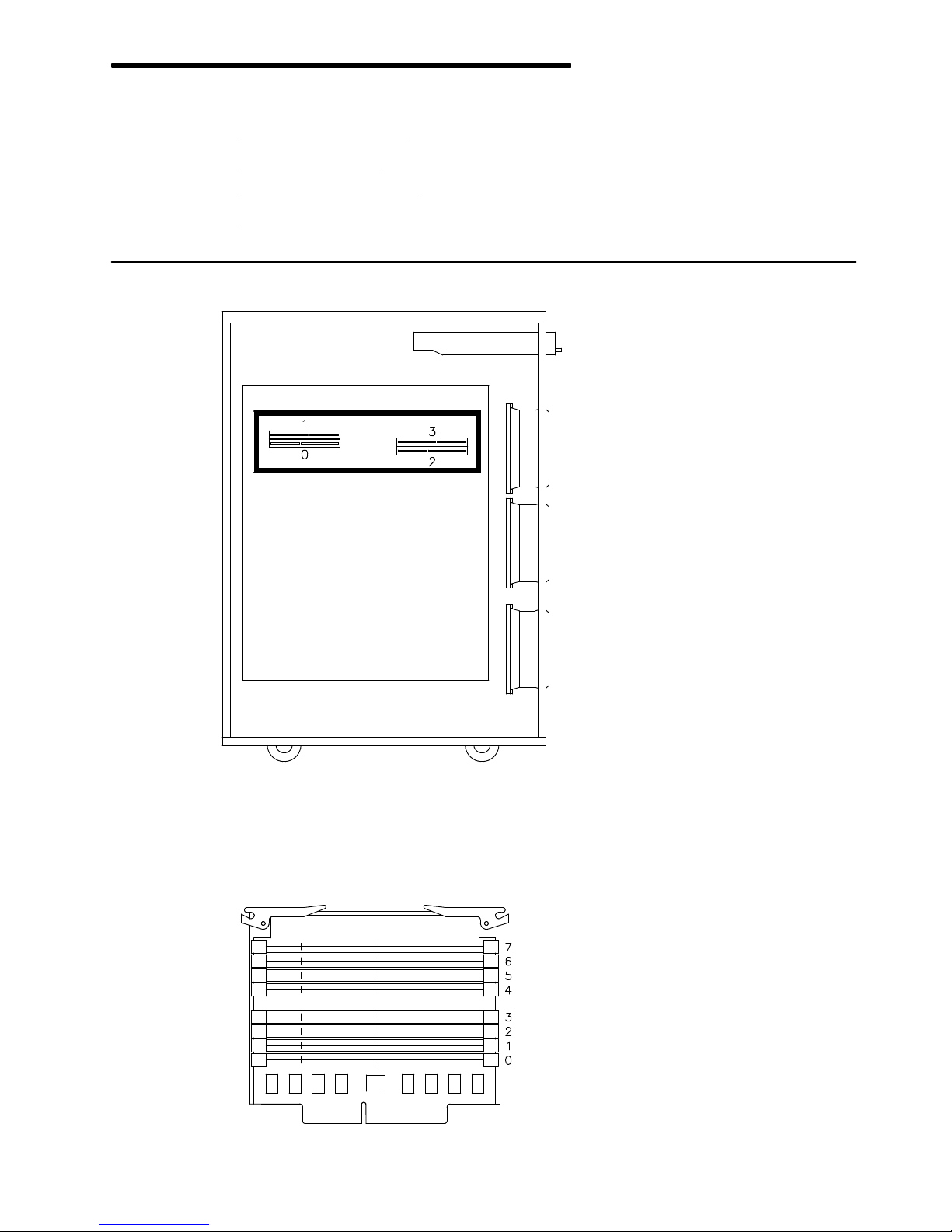
Configuring the System 5-1
Chapter 5. Configuring the System
• Memory Configuration
, below
• CPU Configuration
, on page 5-3
• Controller Configuration
, on page 5-4
• Device Configuration
, on page 5-7.
Memory Configuration
There are four memory connectors on the system planar. They house four memory risers.
There are two types of memory risers:
• FSM risers, housing eight standard synchronous DIMM connectors; these risers are used
for memory configurations requiring more than one memory bank.
Page 84
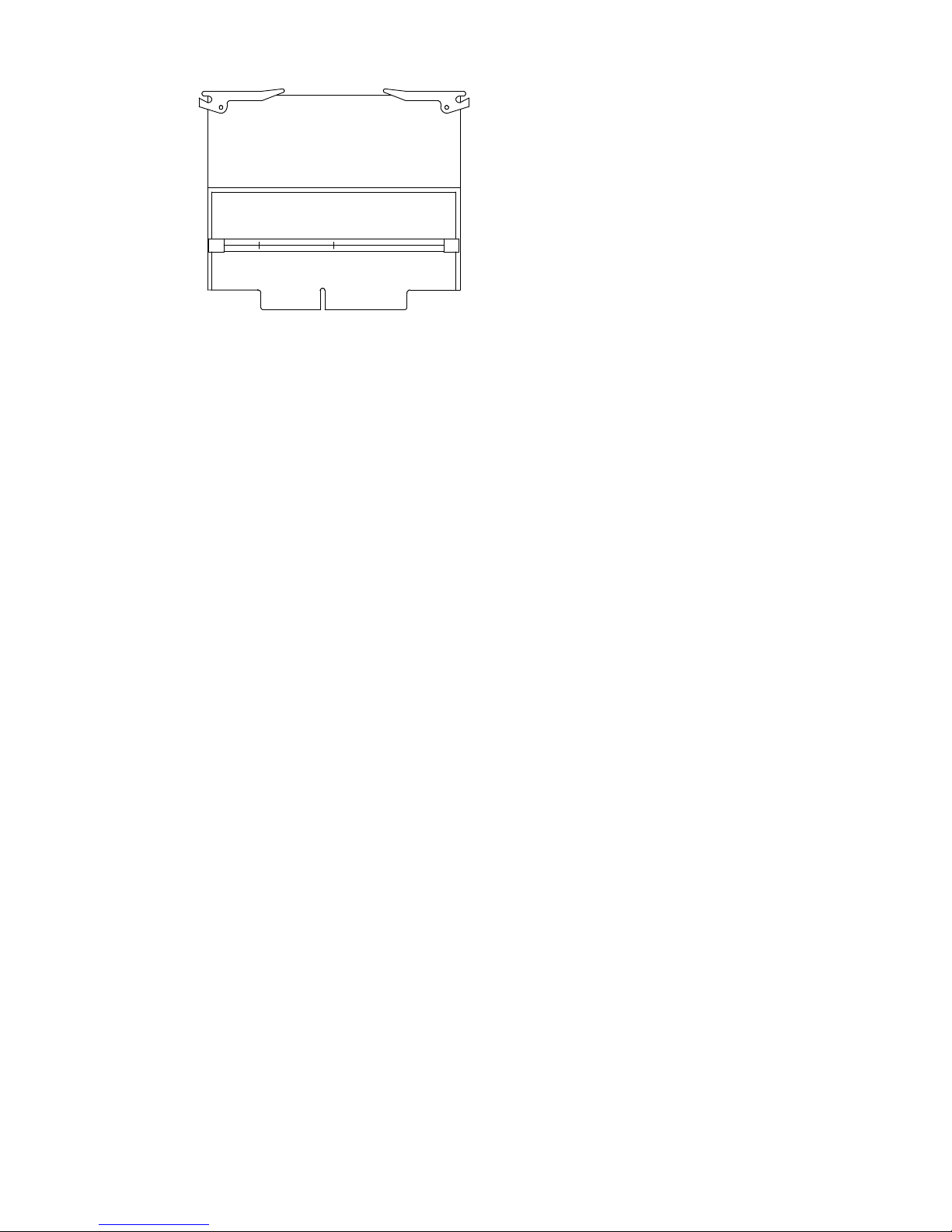
5-2
Setup Guide
• FRE risers, housing one standard synchronous DIMM connector; these risers are used for
entry memory configurations requiring only one memory bank.
Note: It is not possible to install memory DIMM’s directly on the system planar.
The system memory is organized in memory banks made up of four memory DIMM’s each,
one per memory riser.
Minimum memory bank capacity is 256M Bytes (4x64M Byte memory DIMM’s).
Maximum memory bank capacity is 1G Byte (4x256M Byte memory DIMM’s).
Maximum memory capacity is 8G Bytes (8x1G Byte memory banks).
The synchronous DIMM’s have the characteristics summarized below:
DIMM Standard 72 bit 168 pin (PC100 - registered with PLL)
VCC 3.3V
Frequency 100MHz (with CL2)
Functionality Synchronous
Height 1.7 inch max
Package Type TSOPII
Memory DIMM’s belonging to the same memory bank must be plugged into the same
connector on each memory riser; for example: memory bank 7 will be made up of 1 memory
DIMM plugged in position 7 on each memory riser.
Here are some additional configuration rules to be followed to obtain the best performances.
Breaking these rules will decrease performances but will not bring to a loss of memory.
• Install an even number of memory banks
• Install memory banks in couples of homogeneous capacity; each couple of homogeneous
memory banks must be installed in contiguous slots, starting from slot 7-6 and then 5-4,
3-2 and 1-0
• Considering the amount of memory you want to use, prefer using as many couples of
memory banks as you can, provided that you do not compromise a possible future
upgrading.
Page 85
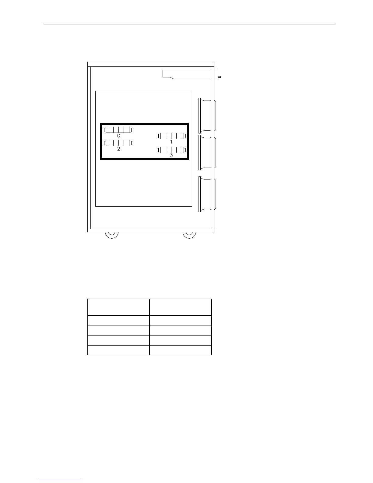
Configuring the System 5-3
CPU Configuration
Each system supports up to four CPU cards which are installed on the system planar
dedicated slots.
The CPU cards must be homogeneous.
Minimum configuration is one CPU, which must be installed in slot 1.
Note: The system cannot work if there is no CPU installed in slot 1.
Install CPU cards according to the following sequence:
Installation
Sequence
CPU Card Slot #
1
st
1
2
nd
0
3
rd
3
4
th
2
Page 86
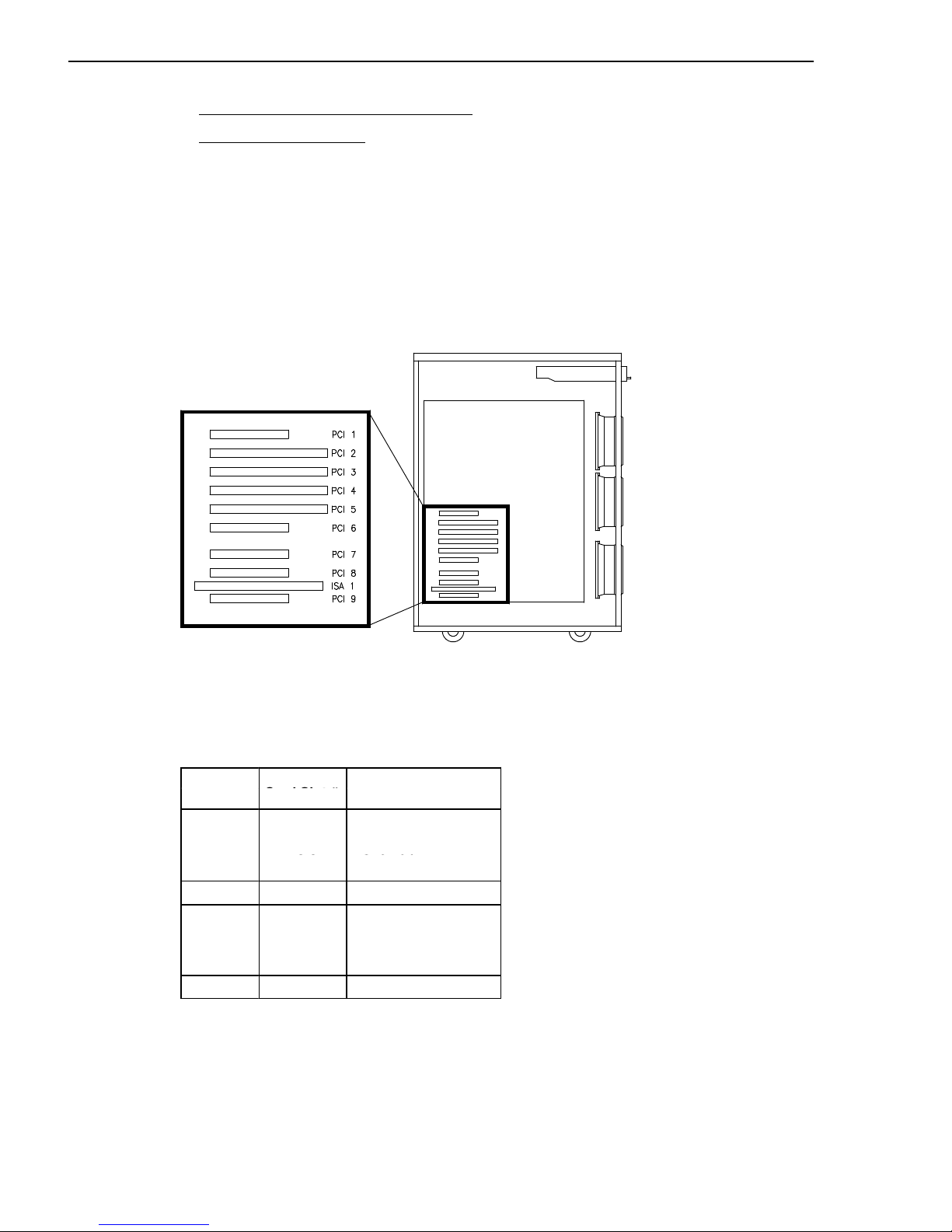
5-4
Setup Guide
Controller Configuration
• PCI/ISA Controller Bus Dependences
, below
• PCI/ISA Controller List
, on page 5-6.
PCI/ISA Controller Bus Dependences
The system base unit can house up to nine PCI controller cards having the characteristics
described below:
• Up to four, 64 bit, 33 MHz, PCI controllers
• Up to five, 32 bit, 33 MHz, PCI controllers.
Moreover, it houses one ISA slot for the internal modem connection.
Note: PCI slot 8 can be used only if the ISA slot is not used and vice-versa.
The system provides two native PCI local busses (PCI0, PCI1). PCI bus 0 generates an
additional PCI bus through a PCI to PCI bridge (PCI0_1). It also generates an ISA bus
through a PCI to ISA bridge.
The following table shows the PCI bus dependences and slot type:
Bus ID
Controller
Slot Type
Card Slot #
PCI #1
PCI1
PCI 32 bit
PCI2
PCI3
PCI 64 bit
PCI 64 bit
PCI3
PCI4
PCI 64 bit
PCI 64 bit
PCI #0 PCI5 PCI 64 bit
PCI #0_1 PCI6
PCI7
PCI8
PCI9
PCI 32 bit
PCI 32 bit
PCI 32 bit
PCI 32 bit
ISA ISA1 ISA 8/16 bit
Page 87

Configuring the System 5-5
The configuration rules are:
• To obtain the best performances, first load PCI busses 0 and 1; when these busses are
fulfilled, load PCI bus 0_1
• 64 Port Asynchronous RS-232/RS-422 controllers cannot be installed in contiguous slots
• Install the graphic controller, if any, before the RAID controller (e.g., if the RAID controller
is installed in PCI slot 4, install the graphic one in PCI slot 2)
• It is possible to install 32 bit controllers in 64 bit slots
• Although it would sensibly decrease performances, it is possible to install 64 bit
controllers in 32 bit slots
• PCI slots 1, 8 and 9 can house only short format controllers (Matrox, being a
medium-long format controller, is allowed in PCI slot 8)
• RAID LVD controller cannot be installed after the PCI bridge, therefore it is not allowed in
slots 6, 7, 8 and 9
• It is suggested, to keep good performances, to install only one Gbit Ethernet controller
per PCI bus, possibly into 64 bit slots and before the PCI bridge.
Refer to the documentation delivered with the controller card for its characteristics and
configuration requirements, if any.
See System Devices Location Map
, on page B-1, for further details about the I/O
subsystem dependences and device location.
The controller cards are identified by a label visible on the external side of the metallic plate
guide. See PCI/ISA Controller List, on page 5-6, for the list of supported controllers and
related labels.
Page 88

5-6
Setup Guide
PCI/ISA Controller List
The controller cards are identified by a label visible on the external side of the metallic plate
guide.
A list of controller cards supported by your system is provided below. Notice that this list is
not meant to be exhaustive and that very recent controller cards could be missing from it.
The description of each controller and its identification label is anyway included in the
controller specific documentation.
The following table provides the cross reference between the controller card model and the
identification label.
Label
Description
1-T Graphics GXT130P
4-J SSA 4-Port RAID
8-T Auto LAN Streamer Token Ring
B1-2 64-bit Graphics (MGA Millennium) 2MB RAM
B1-3 64-bit Graphics (MGA Millennium) 4MB RAM
B2-G 1-Port Synchronous Communication
B2-H 4-Port Synchronous Communication
B2-L 2-Port Synchronous Communication
B3-9 128-Port Async. EIA 232
B3-A 8-Port Async. EIA 232
B3-B 8-Port Async. EIA 422A
B3-C 64-Port Async. EIA 422A
B4-4 SCSI RAID (ULTRA/SE)
B4-5 ULTRA SCSI SE
B4-6 ULTRA SCSI DE
B4-7 Fiber Channel Emulex
B4-8 Fiber Channel Emulex
B4-9 ULTRA-2/LVD SCSI
B4-A Copper Fiber Channel
B4-B Optical Fiber Channel
B5-3 FDDI Fiber UTP Single Ring
B5-4 FDDI Fiber Single Ring
B5-5 FDDI Fiber Dual Ring
B5-6 Ethernet 10/100Mbps
B5-9 155 ATM
B5-A ISA Internal Modem FRANCE
B5-B ISA Internal Modem UK
B5-C ISA Internal Modem BELGIUM
B5-D ISA Internal Modem NETHERLANDS
B5-E ISA Internal Modem ITALY
B5-K ISA Internal Modem US
B5-L ISA Internal Modem GERMANY
B5-M Ethernet ZNYX 10/100Mbps
B5-N Gigabit Ethernet-SX
B5-R Token Ring
B5-S PAN European Modem
Page 89
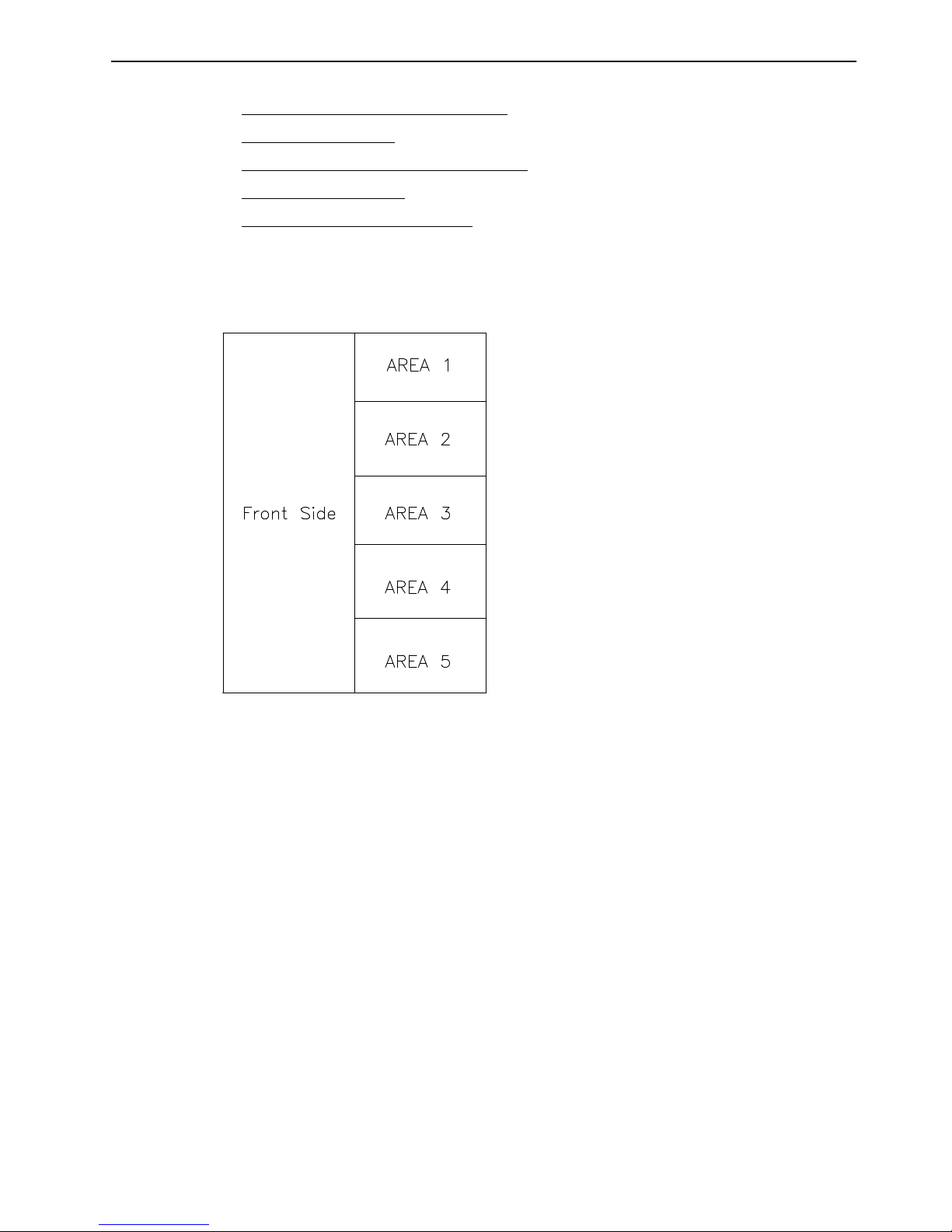
Configuring the System 5-7
Device Configuration
• Media and Disk Configuration Rules
, below
• RAID Configurations
, on page 5-9
• Native High Availability Configurations
, on page 5-9
• SCSI-ID Configuration
, on page 5-10
• Examples of SCSI Connections
, on page 5-12.
Media and Disk Configuration Rules
The system base unit has five device areas. These are located vertically, on the right of the
front side of the system.
• Area 1 hosts up to two 1.6 inch media drives
• Area 2 may host either up to two 1.6 inch media drives or up to three1 inch hard disk
drives
• Areas 3, 4 and 5 may host up to three 1 inch hard disk drives each.
A disk cage is required to install hard disk drives. Each disk cage occupies one area. The
connection to the SCSI bus is done through the disk cage back planes.
No disk cage is required to install media drives. They are installed with their mounting kit on
the unit chassis and directly connected to the SCSI bus.
The system supports ULTRA-2/LVD disk devices (Low Voltage Differential), running at
10000 RPM (Revolutions Per Minute).
The system base unit provides two native SCSI busses.
The first bus, ULTRA/SE (Single Ended), SCSI-0, controls media drives installed in Area1
(and Area 2, if any).
The second bus, ULTRA-2/LVD, SCSI-1, is used to control disks installed in Area 5 and
Area 4.
SCSI hard disk drives can also be controlled by additional SCSI controller cards.
Page 90
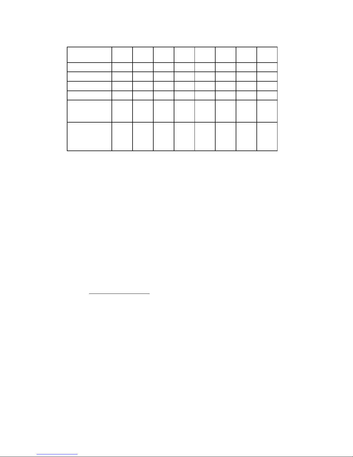
5-8
Setup Guide
Each SCSI bus used to manage disks supports the connection of up to two disk cages, that
means up to six 1 inch hard disk drives.
The table which follows summarizes the possible SCSI connections inside the system unit:
SCSI BUS
Area1Areas
1 - 2
Area2Areas
2 - 3
Area3Area4Area5Areas
4 - 5
SCSI-0 (media) yes yes no no no no no no
SCSI-1 (disks) no no no no no no yes yes
1st RAID bus no no no yes yes no no no
2nd RAID bus no no no no no no yes yes
Additional
ULTRA-2/LVD
SCSI bus
no no no yes yes no no no
Additional
ULTRA/SE bus
(native HA
conf. only)
no no no yes yes no yes yes
Specific rules are given to make the installation and management of SCSI devices easier
and obtain the best performances.
• Install the system disk drive in the upper slot of Area 5 of the base unit
• Install devices beginning always from the upper free slot inside the area
• Within the disk configuration of Areas 3 and 2, install 18Gbyte disks, if any, according to
the following sequence:
– Area 3:
– top (ID 0)
– middle (ID 1)
– low (ID 2)
– Area 2:
– top (ID 8)
– low (ID A)
– middle (ID 9)
• A mix of media drives and hard disk drives inside the same area is not allowed.
Refer to SCSI-ID Configuration
, on page 5-10, for details about the SCSI-ID identification
that the device will acquire once it is installed and for some suggestions about the device
installation sequence.
Refer to the documentation delivered with the device, for characteristics and configuration
requirements, if any.
Page 91

Configuring the System 5-9
RAID Configurations
The RAID feature is supported by a specific RAID controller card.
One or more hard disk drives can be configured in a redundant array. In case of a hard disk
drive failure, the data stored on the faulty device can be recovered from the other devices
owned by the array.
Note: RAID controllers do not support native High Availability configurations.
A maximum of two SCSI busses can be managed in RAID configurations. These are the
busses managing Area 5 (and Area 4 if managed by the same bus) and Area 3 (and Area 2
if managed by the same bus).
Refer to the specific RAID documentation for the setup procedures.
You can find examples of RAID connections in Connections in RAID Configuration
, on
page 5-19.
Native High Availability Configurations
The system supports some Native High Availability configurations, where the full availability
is guaranteed by the physical interconnection and software management of two systems in
such a way that, if one system fails, the other system takes the control and all the activity
goes on without interruption.
Notes:
1. Native High Availability configurations are not supported by RAID controllers.
2. Native High Availability configurations can also include expansion units. Please
refer to the expansion unit specific documentation for details and examples.
3. Native High Availability configurations are not supported by ULTRA-2/LVD
controllers. ULTRA/SE controllers must be used instead.
Refer to the specific native High Availability package documentation for the setup
procedures.
You can find examples of native High Availability connections in Connection in Native
High Availability Configuration, on page 5-21.
Page 92
5-10
Setup Guide
SCSI-ID Configuration
• Media Drive SCSI-ID
, below
• Hard Disk Drive SCSI-ID
, on page 5-11.
Media Drive SCSI-ID
Each SCSI device must be identified on the SCSI bus by a logical address, called SCSI-ID.
Before installing a media drive, it is necessary to define its SCSI-ID. This is normally done
through switches or jumpers placed at the rear of the device. See the documentation
delivered with the device for the details on setting.
Note: If you purchased the media drive from a supplier other than your system supplier, be
sure that the device itself has no SCSI terminator. Refer to the documentation
delivered with the device.
The SCSI-ID to be set for a given media drive depends on the physical position of this
device.
The following table shows the correspondence between physical position and SCSI-ID for
media drives installed on your system. It also gives the suggested installation sequence.
Notice that there is not a direct link between the installation sequence and the SCSI-ID.
Even if the installation sequence is not the one reported here, you must keep the
correspondence between physical position and SCSI-ID.
MEDIA DRIVE CONFIGURATION TABLE
Device
Area
Physical
Position
SCSI-ID
1 M1 6
M2 5
2 M3 4
M4 3
3 - -
- -
4 - -
- -
5 - -
Legend:
Mn = M media drive
n number giving the installation sequence of the devices inside the system unit.
Page 93
Configuring the System 5-11
Hard Disk Drive SCSI-ID
Each SCSI device must be identified on the SCSI bus by a logical address, called SCSI-ID.
Hard disk drives are identified by a SCSI-ID which is automatically defined as the hard disk
drive is installed in a given position. No manual intervention is required.
Note: If you purchased the hard disk drive from a supplier other than your system supplier,
be sure that the device itself has no SCSI-ID set but has the motor delay jumper set.
Refer to the documentation delivered with the device.
The following table details the correspondence between physical position and SCSI-ID for
hard disk drives installed on your system.
It details also the suggested installation sequence.
The suggested sequence fills in:
• First Areas 5 and 4, which can be managed by the embedded SCSI-1 controller, and
• Then Areas 3 and 2, which must be managed by an additional SCSI controller.
If you install one additional SCSI controller, even if all the disk devices you have could be
managed by the embedded SCSI-1 controller, the suggestion is to balance the load
between the two controllers (e.g., if you have four disk devices and two controllers, install
two disk devices in Area 5 and the other two in Area 3).
The installation sequence is not directly linked to the SCSI-ID. Even if the installation
sequence is not the one reported here, the correspondence between physical position and
SCSI-ID remains unchanged.
HARD DISK DRIVE CONFIGURATION TABLE
Device
Area
Physical
Position
SCSI-ID
1 - -
- -
2 D10 8
D11* 9
D12* A
3 D7 0
D8 1
D9 2
4 D4 8
D5 9
D6 A
5 D1 (system disk) 0
D2 1
D3 2
Legend:
Dn = D hard disk drive
n number giving the installation sequence of devices inside the system unit.
* Revert the installation sequence of D11 and D12, in case of 18Gbyte disk.
Page 94

5-12
Setup Guide
Examples of SCSI Connections
Some examples of standard SCSI connections are illustrated in the following pages. These
do not include all possible disk/media device configurations, but they should represent an
easy template to help you perform the SCSI connections inside the base unit.
For each example, both the SCSI controller to bulkhead connections (on the system left
side) and the bulkhead to device area connections (on the system right side) are illustrated.
It is assumed that any SCSI cables inside the system unit are properly in place.
For details on SCSI cables and bulkhead locations mentioned in these examples, please
refer to SCSI Cables Description and Connection, in the Maintenance Guide.
Note: The examples given in the following pages refer to the base unit only. If your system
configuration includes also one or more disk units, you can find the relevant
examples in the Disk Expansion Unit Service Guide.
• Media Device in Area 1 (CD-ROM)
, on page 5-13
• Media Devices in Area 1/Area 2
, on page 5-14
• Disk Devices in Area 5
, on page 5-15
• Disk Devices in Area 5/Area 4, on page 5-16
• Disk Devices in Area 3
, on page 5-17
• Disk Devices in Area 3/Area 2
, on page 5-18
• RAID Controller Managing Two SCSI Busses
, on page 5-19
• RAID Controller Managing One SCSI Bus
, on page 5-20
• Connection in Native High Availability Configuration
, on page 5-21.
Page 95
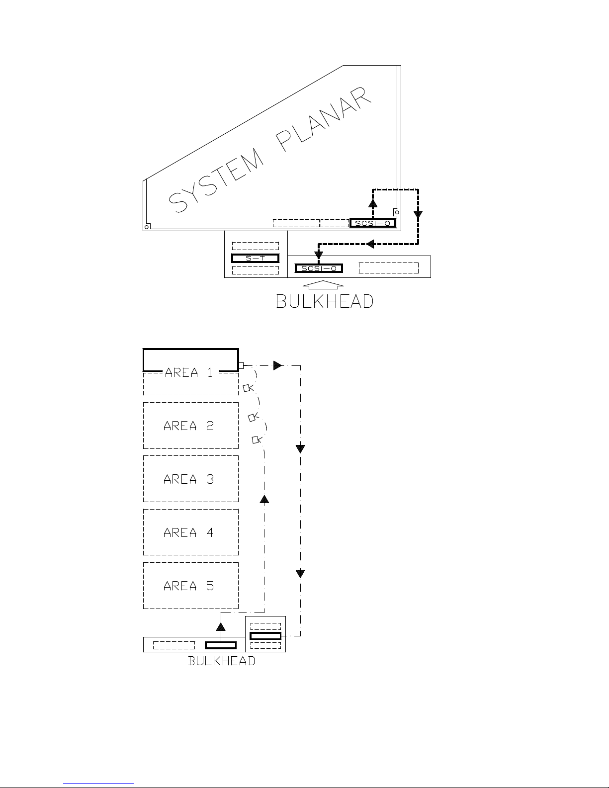
Configuring the System 5-13
Media Device in Area 1 (CD-ROM)
SCSI Controller to Bulkhead Connection
Bulkhead to Device Area Connection
Legend:
S-T SE terminating plug
SCSI-0 Native SCSI bus for media devices
Page 96
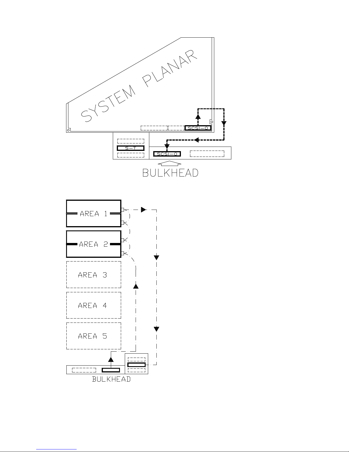
5-14
Setup Guide
Media Devices in Area 1/Area 2
SCSI Controller to Bulkhead Connection
Bulkhead to Device Area Connection
Legend:
S-T SE terminating plug
SCSI-0 Native SCSI bus for media devices
Page 97
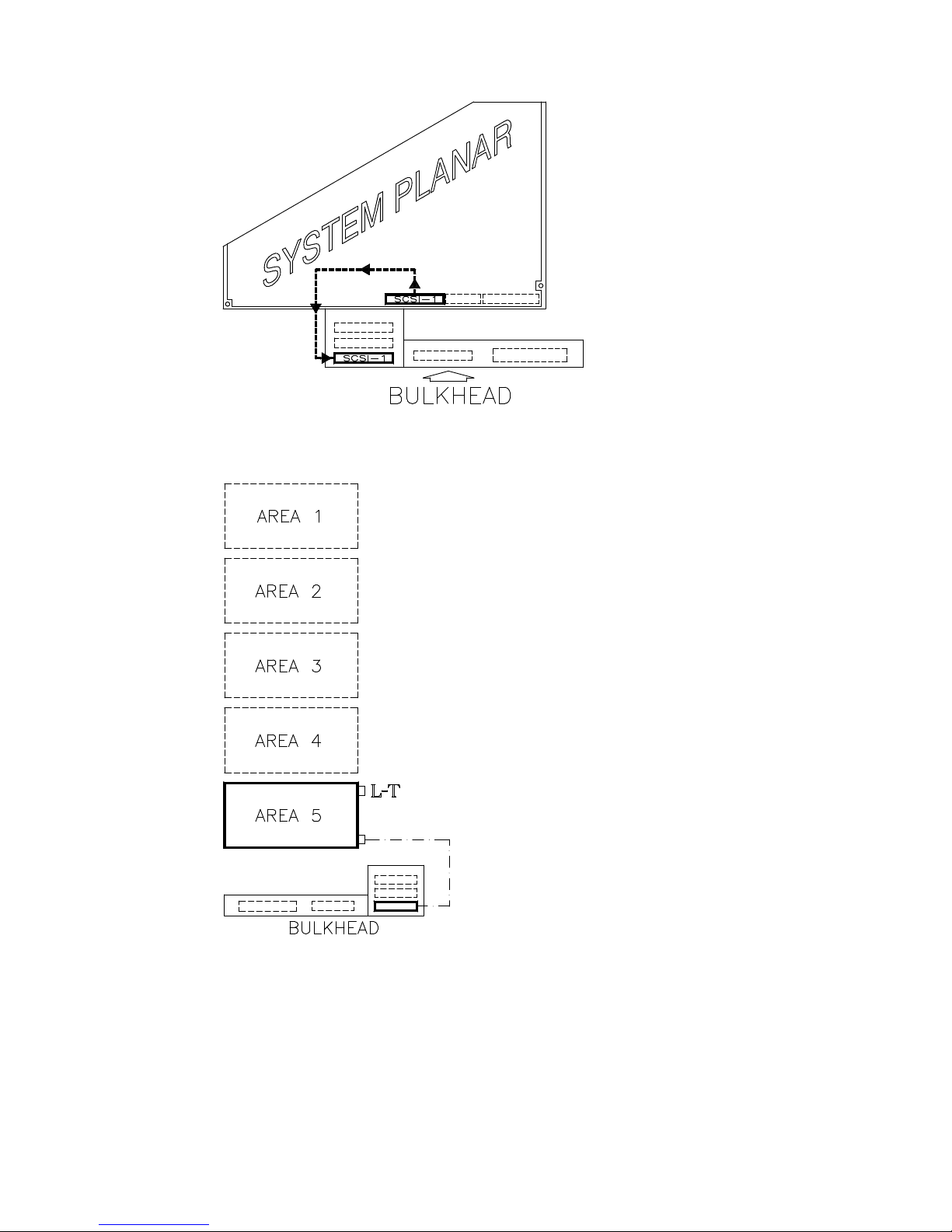
Configuring the System 5-15
Disk Devices in Area 5
SCSI Controller to Bulkhead Connection
Bulkhead to Device Area Connection
Legend:
L-T LVD/SE terminating plug
SCSI-1 Native SCSI bus for disk devices
Page 98

5-16
Setup Guide
Disk Devices in Area 5/Area 4
SCSI Controller to Bulkhead Connection
Bulkhead to Device Areas Connection
Legend:
L-T LVD/SE terminating plug
JC Jumper cable
SCSI-1 Native SCSI bus for disk devices
Page 99
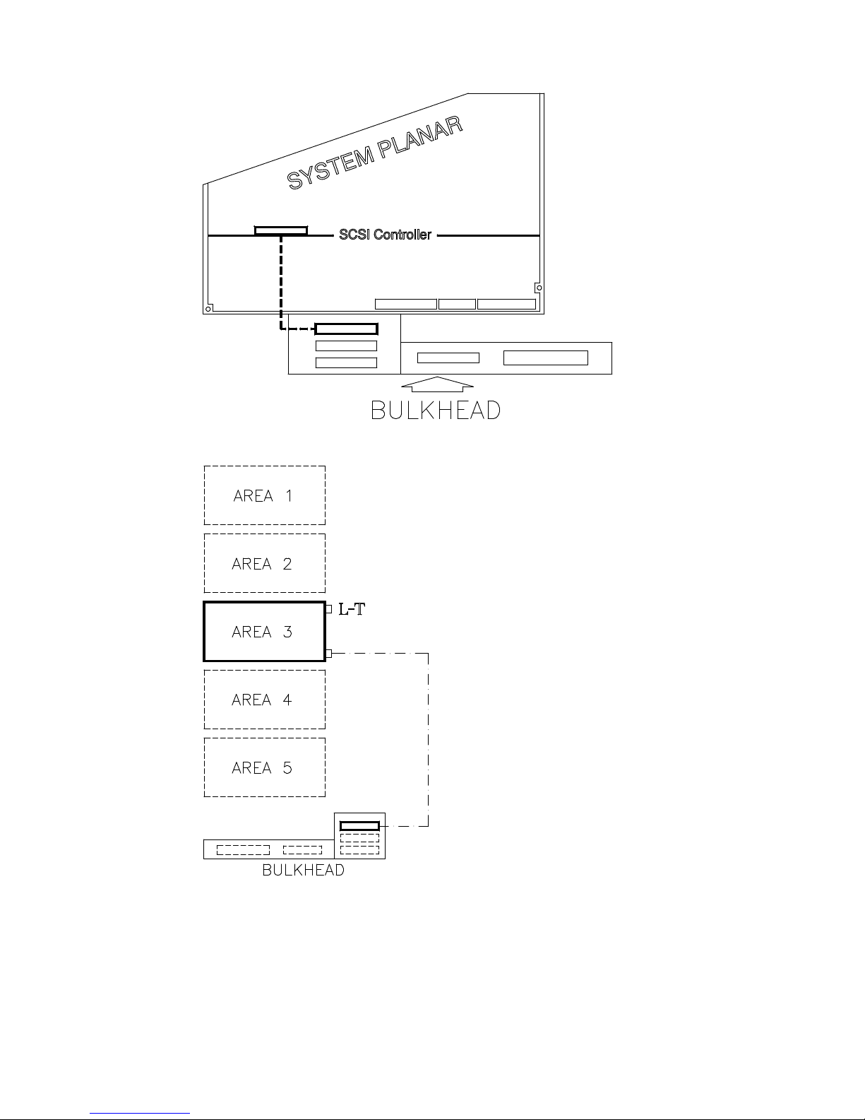
Configuring the System 5-17
Disk Devices in Area 3
SCSI Controller to Bulkhead Connection
Bulkhead to Device Area Connection
Legend:
L-T LVD/SE terminating plug
Page 100
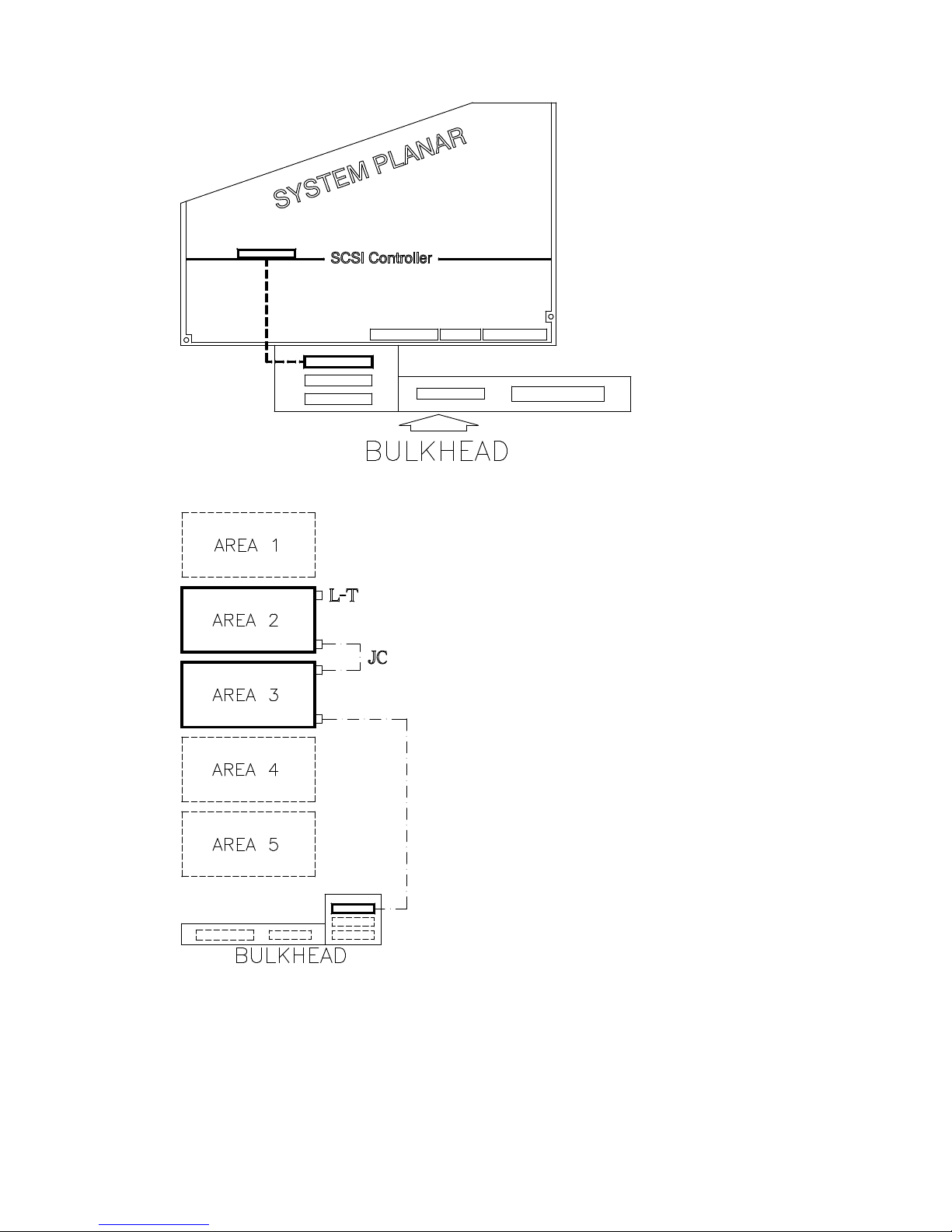
5-18
Setup Guide
Disk Devices in Area 3/Area 2
SCSI Controller to Bulkhead Connection
Bulkhead to Device Areas Connection
Legend:
L-T LVD/SE terminating plug
JC Jumper cable
 Loading...