

Page 1
Building Technologies
Stockwerkterminal FT2010
Stockwerkanzeige FT2011
Installation en
Montage de
Montage fr
Montaje es
Montaggio it
FT2010-A1 / FT2011-A1
Floor repeater terminal FT2010
Floor repeater display FT2011
FT2010-A1 FT2010-C1 FT2011-A1
FT2010-C1
FT2010-A1 / FT2011-A1 / FT2010-C1
I
II
008860_i_--_-2016-04-20 Control Produc ts and Systems
III
Page 2

en
Intended use
Risk of injury to persons and damage to property
nded for stationary installation
install a luster terminal (8) on the rear panel
break out the m ounting holes (2) on the rear side of the
upwards and fix the cover in
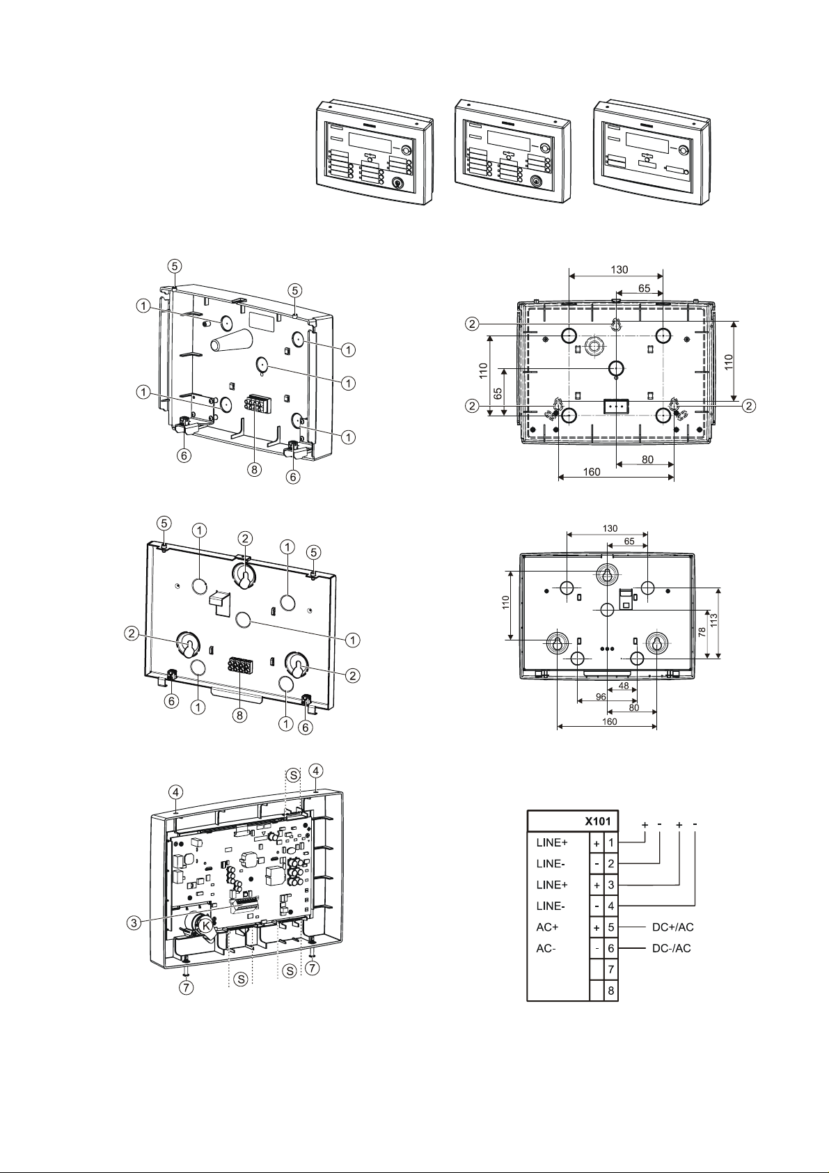
Legend
The floor repeater terminal FT2010 enables the fire
detection system to be displayed and op erated in a
simplified way. The floor repeater display FT2011
only features display functions. The display on the
FT20xx is synchronized with stations of the
configured visibility a nd shows the same event
texts. Both devices are operated on the FDnet detector
line.
Scope of delivery
The following are included in the scope of delivery:
l Cover with operating unit
l Rear panel
l Inscription strips
l M 6/40 mm screws
l M 4.5-6 nylon dowels
Safety instructions
Please observe the following safety instructions:
l The devices are only inte
in dry rooms.
l The devices may only be connected to the FDnet
detector line.
l An external supply must be electrically isolated from
the installation’s supply.
l Where cables are too thick for the terminal (3), it is
possible to
as a transitory pi ece.
I Rear panel interior (plastic)
II Rear panel surface (steel sheet)
III Cover with operating unit
S Slits for inscription strips
K Key switch
1 Breakout openings for cables (5 pcs.)
2 Three mounting holes for wall mounting
3 X101 connector with 8-pin terminal
4 Holes f or cam-locks (2 pcs.) of rear panel
5 Cam-locks for mounting cover (2 pcs.)
6 Holdi ng angles (2 pcs.)
7 Sealing studs (2 pcs.)
8 Luster terminal, 4-pin (opti onal)
Surface mounting
1. Break out the required cable openings (1) on the rear
panel (I or II).
2. If using the plastic rear panel (I), you also need t o
rear panel.
3. Mark the drilling points for the 3 mounting holes (2),
drill the holes and insert the dowels supplied.
4. Pull the cabl es of the detector line and, where
applicable, the external supply, through the breakout
openings (1) on the rear panel (I or II).
5. Screw the rear panel tightly in place.
6. Connect the cable to the terminal (3) in accordance
with the connection diagram.
7. Hook the cover with (III) with the holes (4) over the
cam-locks (5) on the rear panel.
8. Push the cover (III) down over the holding angles (6),
press the sealing studs (7)
place by giving the seali ng studs a quarter turn.
2
Building Technologies 008860_i_--_--
Fire Safety 2016-04- 20
Page 3
de
Gefahr von Personen
-
und Sachschäden
Rückwand (I) müssen Sie zusätzlich
Verwendungszweck
Das Stockwerkterminal FT2010 erlaubt die reduzierte
Anzeige und Bedi enung des Brandmeldesystems. Die
Stockwerkanzeige FT2011 hat nur Anzeigefunktionen.
Die Anzeige am FT20xx ist synchronisiert mit Stationen
der konfigurierten Sicht und zeigt dieselben
Ereignistex te.
Beide Geräte werden an der FDnet -Melderlini e betrieben.
Lieferumfang
Zum Lieferumf ang gehören:
l Deckel mit Bedieneinheit
l Rückwand
l Beschriftungsstreifen
l Schrauben M 6/40 mm
l Nylon-Dübel M 4,5-6
Sicherheitsh inweise
Beachten Sie die folgenden Sicherheitshinweise:
l Die Geräte sind nur für ortsfeste Montage in trockenen
Räumen vorgesehen.
l Die Geräte dürfen nur an der FDnet-Melderli nie
angeschlossen werden.
l Eine externe Speisung muss galvanisch von der
Anlagenspeisung getrennt sein.
l Für Kabel, die zu dick sind für die Steck klemme (3),
kann eine Lüsterkl emme (8) als Übergangsstück in der
Rückwand montiert werden.
Legende
I Rückwand tief (Kunststoff)
II Rückwand flach (St ahlblech)
III Deckel mit Bedieneinheit
S Schlitze für Beschriftungsstreifen
K Schlüsselschalter
1 Ausbruchsöffnungen für Kabel (5 Stk.)
2 Drei Befestigungslöcher für Wandbefestigung
3 Stecker X101 mit Steckklemme 8-polig
4 Löcher für Haltenocken (2 Stk.) der Rückwand
5 Haltenocken für Deckelbefestigung (2 Stk.)
6 Spannverschluss (2 Stk.)
7 Verschlusszapfen (2 Stk.)
8 Lüsterklemme 4-polig (opti onal)
Aufputzmontage
1. Brechen Sie an der Rückwand (I) oder (II) die
gewünschten Ausbruchsöffnungen (1) für die Kabel aus.
2. Bei der Kunststoff-
an der Rückseite der Rückwand die
Befestigungslöcher (2) ausbrechen.
3. Markieren Sie die Bohrungen für die 3
Befestigungslöcher (2), bohren Sie die Löcher und
setzen Sie die mitgelieferten Dübel ein.
4. Ziehen Sie die Kabel der M elderl inie und
gegebenenfalls der externen Speisung, durch die
Ausbruchsöffnungen (1) in der Rückwand (I) oder (II).
5. Schrauben Sie die Rück wand fest.
6. Schließen Sie die Kabel gem äß Anschlussschema an
der Steckklemme (3) an.
7. Hängen Sie den Deckel (III) mit den Löchern (4) über
die Haltenocken (5) der Rückwand.
8. Klappen Sie den Deckel (III) nach unten über die
Spannverschlüsse (6), drücken Sie die
Verschlusszapf en (7) nach oben und befestigen Si e
den Deckel mit einer Vierteldrehung der
Verschlusszapfen.
Building Technologies 008860_i_--_-Fire Safety 2016-04- 20
3
Page 4
fr
ie.
Risque de dommages corporels et matér
iels
Application
Le terminal répétiteur FT2010 permet l'utilisation et
l'affichage limités du système de dét ection d'incend
Le tableau répétiteur FT2011 ne dispose que de
fonctions d’affichage. L'affichage sur l e FT20xx est
synchronisé avec les stations de la visibilité
configurée et montre les mêmes textes
d'événements. Les deux appareils sont exploit és sur
la ligne de détection FDnet.
Fourniture
Font partie de la fourniture :
l Couvercle avec unité centrale
l Paroi arrière
l Etiquettes de repérage
l Vis M 6/40 mm
l Chevilles en nylon M 4,5-6
Instructions de sécurité
Légende
I Paroi arrière profonde (plastique)
II Paroi arrière plate (tôle d’aci er)
III Couvercle avec unité centrale
S Fentes pour étiquettes de repérage
K Commutat eur à clef
1 Préparations d’ouvertures pour le passage des câbles
(5 unités)
2 Trois trous pour la fixation murale
3 Connecteur X101 av ec bloc de joncti on enfichabl e à 8
pôles
4 Trous pour cames de maintien de la paroi arri ère (2
unités)
5 Cames de maintien pour fixation du couvercle (2
unités)
6 Fermeture à genouillère (2 pièces)
7 Bouchon de fermeture (2 unités)
8 Domino 4 pôles (en option)
Montage en saillie
Respecter l es instr uctions de sécuri té suivantes:
l Les appareils sont destinés à un montage à
demeure dans des locaux secs uni quement.
l Les appareils ne doivent être raccordés qu’à l a
ligne de détection FDnet.
l L'alimentation externe doit être isolée
galvaniquement de la tension de l'installation.
l Pour les câbles trop épais pour le bloc de j onction
(3), il est possible de monter un domino (8) dans l a
paroi arrière comme pièce d’adaptation.
1. Enfoncez dans la paroi arrière (I) ou (II) les ouvertures de
passage des câbles (1) désirées.
2. Pour la paroi arri ère en plastique (I), il faut en plus
enfoncer dans la paroi arrière les trous de fixation (2).
3. Repérez les perçages pour les 3 trous de fixation (2),
percez les trous et introduisez les chevilles fournies en
accompagnement.
4. Tirez les câbles de la ligne de détection et de
l’alimentation externe le cas échéant à travers les trous
pratiqués (1) de la paroi arrière (I) ou (II).
5. Fixez la paroi arrière fermement.
6. Raccordez les câbles sur le bloc de jonction (3)
conformém ent au schéma de rac cordement.
7. Accrochez le couvercle (III) aux trous (4) au-dessus des
cames de maintien (5) de la paroi arrière.
8. Rabattez l e couvercle (III) vers l e bas au moyen des
fermetures à genouillère (6), poussez les bouchons de
fermeture (7) vers le haut et fixez le couvercle en tournant
les bouchons de fermet ure d'un quart de tour.
4
Building Technologies 008860_i_--_--
Fire Safety 2016-04- 20
Page 5
es
bre las levas
Baje la tapa (III) sobre los cierres acodados (6), apri ete
Uso previsto
El terminal repetidor de planta FT2010 permite la
indicación y el m anejo reducidos del sistem a de
detección de incendios. El display repetidor de planta
FT2011 sólo tiene funciones de indicación. La indicación
en el FT20xx está sincronizada con las estaciones de la
visibilidad configurada y muestra los mismos textos de
evento.
Ambos dispositivos se operan en la línea de detectores
FDnet.
Volumen de suministro
El volumen de suministro incluye:
l Tapa con unidad de operación
l Parte trasera
l Tiras de inscripción
l Tornillos M 6/40 mm
l Tacos de nail on M 4,5-6
Normas de seguridad
Peligro de daños personales y materiales
Observe las siguientes normas de seguridad:
l Los dispositiv os sólo están previstos para el montaje
estacionario en lugares secos.
l Los dispositivos sólo deben conectarse a la línea de
detectores FDnet.
l Una alimentación externa debe estar galvánicamente
separada de la alimentación de la instalación.
l Para cables que son demasiado gruesos para el
terminal enchufable (3) puede montarse una caja de
conexión (8) como pieza de transición en la parte
trasera.
Leyenda
I Parte trasera profunda (plástico)
II Parte trasera plana (chapa de acero)
IIITapa con unidad de operación
S Ranuras para tiras de inscripción
K Conmutador de llave
1 Aberturas pretroquel adas para cables (5 unds.)
2 Tres orificios para l a fijación en l a pared
3 Conector X101 con terminal enchufable de 8 polos
4 Orificios para levas de sujeción (2 unds.) de la parte
trasera
5 Levas de sujeción para la fijación de la tapa (2
unds.)
6 Cierre acodado (2 unds.)
7 Piv ote de cierr e (2 unds.)
8 Caja de conexión de 4 polos (opcional)
Montaje en superfi cie
1. Abra en la parte trasera (I) o (II) las aberturas
pretroqueladas deseadas (1) para los cables.
2. En la parte trasera de plástico (I), adicionalmente
deberá abrir los orificios de fijación (2) en el lado
posterior de la parte trasera.
3. Marque los tal adros para los 3 orificios de fijación (2),
taladre los orificios e inserte los tacos suministrados.
4. Pase los cables de la línea de det ectores y, dado el
caso, de la alimentación externa por las aberturas
pretroqueladas (1) de la parte trasera (I) o (II).
5. Atornille la parte trasera.
6. Conecte los cables de acuerdo con el diagrama de
conexión en el termi nal enchufable (3).
7. Coloque la tapa (III) con los orificios (4) so
de sujeción (5) de l a parte trasera.
8.
hacia arriba los pivotes de cierr e (7) y fij e la tapa con
un cuarto de giro de los pivotes de cierre.
Building Technologies 008860_i_--_-Fire Safety 2016-04- 20
5
Page 6

it
Pericolo di danni alle persone e alle cose
Gli apparecchi sono concepiti solo per il montaggio
Destinazione d'uso
il terminale ripetitore di piano FT2010 consente la
visualizzazione ridotta e il com ando del sistema di
rivelazione incendio. Il display ripetitore di piano
FT2011 possiede solo funzioni di visualizzazione. La
visualizzazione sull'FT20xx è sincronizzata con le
stazioni della visibilità c onfigurata e mostra gli stessi
testi di eventi. Entrambi gli apparecchi vengono fatti
funzionare sul la linea di rivelatori FDnet.
Volume di fornitura
Sono forniti in dotazione:
l Coperchio con unità di comando
l Pannello posteriore
l Etichette con scritte
l Viti M 6/40 mm
l Tasselli di nylon M 4,5-6
Avvertenze di sicu rezza
Rispet tare le seguenti avvertenze di s icurezza:
l
stazionario in ambienti asciutti.
l Gli apparecchi dev ono essere collegati solo alla
linea di rivelatori FDnet.
l Un'alimentazione esterna deve essere isolata
galvanicam ente dall'alimentazione dell'impianto.
l Per cavi che sono troppo spessi per il morsetto a
innesto (3), è possibile montare un morsetto
isolante (8) come raccordo sul pannello posteriore.
Leggenda
I Pannello posteriore profondo (plastica)
II Pannello posteriore piatto (l ami era di acciaio)
III Coperchio con unità di comando
S Fessure per le etichette con scritte
K Commutat ore a chiave
1 Aperture per il cavo (5 pezzi)
2 Tre f ori di fi ssaggio per il fissaggio alla parete
3 Spina X101 con m orsetto a innesto a 8 poli
4 Fori per le camme di tenuta (2 pezzi) del pannello
posteriore
5 Camme di tenuta per il fissaggio del coperchi o (2
pezzi)
6 Morsetto a fascia (2 pezzi)
7 Perno di chiusura (2 pezzi)
8 Morsetto isolante 4 poli (opzionale)
Montaggio a parete
1. Sul pannello posteriore (I) o (II), realizzare le aperture (1) per
i cavi.
2. Nel pannello posteriore in plastica (I) è inoltre necessari o
praticare i fori di fissaggio (2) sulla parte posteriore del
pannello posteriore.
3. Segnare i punti di foratura per i 3 fori di fissaggio (2),
realizzare i fori e inserire i tasselli in dotazione.
4. Tirare i cavi dell a linea di rivelatori e, all'occorrenza,
dell'alimentazione esterna, att raverso le aperture (1) nella
parete posteriore ( I) o (II).
5. Avvitare la parete posteriore.
6. Collegare i cavi al morsetto a innesto (3) secondo lo
schema di collegamento.
7. Agganciare il coperchio (III) con i fori (4) sopra le camme
di tenuta (5) del pannell o posteriore.
8. Abbassare il coperchio (III) attraverso i morsetti a fascia
(6), premere verso l’alto i perni di chiusura (7) e fissare il
coperchio ruot ando i perni di chiusura di un quarto di giro.
6
Building Technologies 008860_i_--_--
Fire Safety 2016-04- 20
Page 7

License
strftime.c
Date to string conversion
Copyright (C) 2002 Michael Ringgaard. All rights reserved.
Redistribution and use in source and binary forms, with or without
modification, are permitted provided that the following conditions
are met:
1. Redistributions of source code must retain the above copyright
notice, this list of conditions and the following disclaimer.
2. Redistributions in binary form must reproduce the above copyright
notice, this list of conditions and the following disclaimer in the
documentation and/or other materials provided with the distribution.
3. Neither the name of the project nor the names of its contributors
may be used to endorse or promote products derived from this software
without specific prior written permission.
THIS SOFTWARE IS PROVIDED BY THE COPYRIGHT HOLDERS AND CONTRIBUTORS "AS IS" AND
ANY EXPRESS OR IMPLIED WARRANTIES, INCLUDING, BUT NOT LIMITED TO, THE
IMPLIED WARRANTIES OF MERCHANTABILITY AND FITNESS FOR A PARTICULAR PURPOSE
ARE DISCLAIMED. IN NO EVENT SHALL THE COPYRIGHT OWNER OR CONTRIBUTORS BE LIABLE
FOR ANY DIRECT, INDIRECT, INCIDENTAL, SPECIAL, EXEMPLARY, OR CONSEQUENTIAL
DAMAGES (INCLUDING, BUT NOT LIMITED TO, PROCUREMENT OF SUBSTITUTE GOODS
OR SERVICES; LOSS OF USE, DATA, OR PROFITS; OR BUSINESS INTERRUPTION)
HOWEVER CAUSED AND ON ANY THEORY OF LIABILITY, WHETHER IN CONTRACT, STRICT
LIABILITY, OR TORT (INCLUDING NEGLIGENCE OR OTHERWISE) ARISING IN ANY WAY
OUT OF THE USE OF THIS SOFTWARE, EVEN IF ADVISED OF THE POSSIBILITY OF
SUCH DAMAGE.
Building Technologies 008860_i_--_-Fire Safety 2016-04- 20
7
Page 8
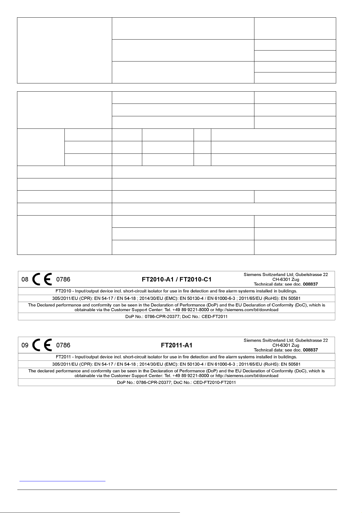
Approvals
FT2010-A1
VdS G208011
LPCB 126bp/02
Weight
Dimensions FT2010-A1
FT2011-A1
FT2010-C1
Operating voltag e DC
Operating voltag e AC
Protection category
Altitude
Ambient conditions
FT2011-A1
VdS G208011
LPCB 126bp/03
FT2010-C1
VdS –
LPCB 126bp/02
FT2010-A1 900 g
FT2011-A1 860 g
FT2010-C1 1340 g
(W x H) 283 x 205 mm
(W x H) 283 x 205 mm
(W x H) 283 x 205 mm
(D) 79 mm
(D) 79 mm
(D) 45 mm
DC 20…30 V
AC 15…18 V
IEC 60529 / IEC 60529 IP30
Max. 4000 m above sea level
Operating temperature -8…+42 C
Storage temperature -20…+60 C
Air humidity
≤ 95 % rel.
Issued by
Siemens Switzerland Ltd
Building Technologies Division
International Headquarters
Gubelstrasse 22
CH-6301 Zug
Tel. +41 41 – 724 24 24
www.siemens.com/buildingtechnologies
Document ID 008860_i_--_-- Manual FS20/FS720
Edition 2016-04-20 A5Q00020513 Register 5
Technical spec ific ations and availability su bject to change without notice.
© Siemens Switzerland Lt d, 2006
 Loading...