

Buhler Versatile 2290, Versatile 2335, Versatile 2360, Versatile 2375, Versatile 2425 Operator's Manual
Page 1

Page 2

TO THE OWNER:
This manual contains information concerning the operation, adjustment, and maintenance of Buhler Versatile
4WD tractors. You have purchased a dependable machine, but only by proper care and operation can you
expect to receive the performance and long service built into this tractor. HAVE ALL OPERATORS READ
THIS MANUAL CAREFULLY AND KEEP IT AVAILABLE FOR READY REFERENCE.
The tractor was designed to pull agricultural equipment in agricultural applications at field speeds of 7.2 KPH
(4.5 MPH) or greater. Proper ballasting to provide equal traction to front and rear axles under moderate to
heavy load will improve tractor performance and life. Using the tractor in industrial only applications (ie. road
building) will not be covered by warranty.
Your Buhler Versatile dealerwill instruct you in the general operation ofyour tractor.Your dealer’sstaff of factory-trained service technicians will be glad to answer any questions that may arise regarding the operation of
your tractor.
For engine maintenance not covered in this manual, follow the instructions provided in the Cummins Engine
Operator’s manual. Before putting the tractor in service, become familiar with the procedures outlined in both
manuals.
The warranty coverage that is extended to your Buhler Versatile 4WD tractor is explained in the Warranty and
Limitation of Liability form. Your dealer will provide you with a copy of the warranty and retain a copy which you
have signed. After you read the warranty, ask your dealer to explain any points that you may not understand.
Do not modify, alter, or permit anyone else to modify or alter this tractor or any of its components, or any tractor
function, without first consulting an authorized Buhler Versatile dealer. If you have any questions regarding
tractor modifications, contact Buhler Versatile Inc., 1260 Clarence Ave. Winnipeg MB, R3T 1T2.
Your safety, and the safety of those around you depends upon the care and good judgement you use while
operating this equipment. Read the safety precautions carefully.
For a complete list of the delivery service checks performed by your dealer, refer to the Delivery Report in this
manual. The first copy is your record of the service performed and the second copy, which is to be removed
from the manual, is your dealer’s record. MAKE SURE THAT YOU AND THE DEALER SIGN BOTH COPIES.
After you have operated the tractor for 50 hours, have your dealer perform the factory recommended 50-hour
service. Return this manual with your tractor to the dealer so the “First 50-Hour Service” checklist can be filled
out. You will be responsible for the cost of lubricants, fluids, filters and other items replaced as part of normal
maintenance. Prior to taking the tractor to your selling dealer for service, it is recommended that you contact
them to determine any other charges for which you may be responsible.
All data given in this book is subject to production model variations. Dimensions and weights are approximations only, and the illustrations do not necessarily show tractors in standard condition. For exact information
about any particular tractor, please consult your Buhler Versatile dealer.
CAUTION: THIS SYMBOL IS USED THROUGHOUT THIS BOOK WHENEVER PERSONAL SAFETY IS
INVOLVED. TAKE TIME TO READ AND FOLLOW THE INSTRUCTIONS. BE CAREFUL!
CAUTION: PICTURES IN THIS MANUAL MAY SHOW PROTECTIVE SHIELDING OPEN OR REMOVED
TO BETTER ILLUSTRATE A PARTICULAR FEATURE OR ADJUSTMENT.
BE CERTAIN, HOWEVER, TO CLOSE OR REPLACE ALL SHIELDING BEFORE OPERATING THE
MACHINE.
Buhler Versatile Inc. is continually striving to improve its products. We reserve the right to make improvements
or changes when it becomes practical and possible to do so, without incurring any obligationto make changes
or additions to the equipment sold previously.
386
IMPROVEMENTS
Page 3

CALIFORNIA EMISSION CONTROL WARRANTY STATEMENT
Your Warranty Rights and Obligations
The California Air Resources Board and Buhler Versatile are pleased to explain the emission control system warranty on your engine. In
California, new 1996 and later heavy-duty off-road engines from 175 to 750 HP must be designed, built, and equipped to meet the State’s
stringent anti-smog standards. Buhler Versatile must warrant the emission control system on your engine for the periods of time listed below,
provided there has been no abuse, neglect, or improper maintenance of your engine.
Your emission control system includes parts such as the fuel injection system and the air induction system.
Manufacturer’s Warranty Coverage:
The 1996 and later heavy-duty off-road engines are warranted from the original date of delivery for five years or 3,000 hours of operation,
whichever occurs first. If any emission-related part on your engine is defective, the part will be repaired or replaced by Buhler Versatile.
Owner’s Warranty Responsibilities:
D As the heavy-duty off-road engine owner, you are responsible for the performance of the required maintenance listed in your owner’s
manual. Buhler Versatile recommends that you retain all receipts covering maintenance on your heavy-duty off-road engine, but Buhler
Versatile cannot deny warranty solely for the lack of receipts or for your failure to ensure the performance of all scheduled maintenance.
D As the heavy-duty off-road engine owner, you should, however, be aware that Buhler Versatile may deny you warranty coverage if your
heavy-duty off-road engine or a part has failed due to abuse, neglect, improper maintenance, or unapproved modifications.
D Your engine is designed to operate on commercially available diesel fuel only. Use of any other fuel may result in your engine no longer
operating in compliance with California’s emissions requirements.
D You are responsible for initiating the warranty process. The ARB suggests that you present your heavy-duty off-road engine to a Buhler
Versatile dealer as soon as a problem exists. The warranty repairs should be completed by the dealer as expeditiously as possible.
If you have questions regarding your warranty rights and responsibilities, you should contact the Buhler Versatile Warranty Department.
D Prior tothe expiration of the warranty, youmust give notice of any failure of an emission control warranted part.Such notice must be given
to Buhler Versatile or an authorized dealer, and you must deliver the engine to the repair location.
D You, the owner, are responsible for incidental costs incurred by yourself or your employees as a result of a warrantable failure. Examples
of such costs are communication expenses, meals and lodging.
D The owner is responsible for any business costs or losses, any “downtime” expenses and any “cargo” damage which result from the
failure of a warranted part. Buhler Versatile is not responsible fo r other incidental or consequential damages, including but not limited to
fines, theft, vandalism or collisions.
Parts covered:
This emission control system warranty applies to the following 675TA/V emission control parts.
Fuel Injection Pump
Fuel Injectors
Turbocharger
Intake Manifold
Charge Air Cooler
Exhaust Manifold
Any replacement part, equivalent in performance and durability, may be used in the performance of any maintenance or repairs and must be
provided without charge to the owner. The use of these parts does not reduce the warranty obligations of Buhler Versatile. However, Buhler
Versatilerecommends theuse of new, genuine Buhler Versatile service parts or Buhler Versatileapproved rebuiltparts andassemblies. Buhler
Versatile also recommends that the engine be serviced by a Buhler Versatile authorized dealer.
Buhler Versatile Responsibilities
Warranty work will be provided at no charge to the owner at any authorized dealer, using new genuine Buhler Versatile service parts or Buhler
Versatile approved rebuilt parts or assemblies..
The ownerwill not be charged for diagnostic labor which leads to the determination that a warranted part isdefective, if the diagnostic work was
performed at a warranty station.
Buhler Versatile is liable for damages to other engine components caused by the failure under warranty of any warranted part.
Warranty Limitations
Buhler Versatile is not responsible for failures resulting from abuse or neglect by owner or operator.
Buhler Versatile warrants to the ultimate purchaser and each subsequent purchaser that the engine is designed, built, and equipped so as to
conform with all applicableregulations adoptedby the Air Resources Board, and that it isfree fromdefects in materials and workmanship which
cause the failure of a warranted part.
Any warranted part which is not scheduled for replacement as required maintenance, or which is scheduled only for regular inspection to the
effect of “repair or replace as necessary” is warranted for the warranty period.
Any warranted part which is scheduled for replacement as required maintenance is warranted for the period of time prior to the first scheduled
replacement point for that part.
Buhler Versatile is liable for damages to other engine components caused by the failure under warranty of any warranted part.
0-1
Page 4

FEDERAL EMISSIONS WARRANTY
(California owner’s emissions warranty is covered elsewhere)
Buhler Versatile warrants that your new 2001 and later heavy-duty off-road diesel engine was designed, built, and equipped to conform to
applicable U.S. Environmental Protection Agency regulations for a period of use of five years or 3,000 hours of operation, whichever occurs
first.
The new model year, class of diesel engine, and emission application determination for your engine are identified on the emission control
information label affixed to the top of your engine’s rocker arm cover. The warranty period begins on the date the new equipment is sold to the
first retail purchaser.
Any emission control system parts which are proven defective during normal use will be repaired or replaced during the warranty period. The
warranty repairs and service will be performed by any authorized Buhler Versatile dealer at the dealer’s place of business, with no charge for
parts or labor (including diagnosis).
As the engine owner, you are responsible to perform all the required maintenance listed in your owner’s manual. Buhler Versatile will notdeny
an emission warranty claim solely because you have no record of maintenance; however, a claim may be denied if your failure to perform
maintenance resulted in the failureof awarranted part. Receipts covering regularmaintenance shouldbe retained inthe eventof questions and
these receipts should be passed on to each subsequent owner of the engine.
It is recommended replacement parts used for maintenance or repairs be Buhler Versatile Service Parts to maintain the quality originally
designed into your emission certified engine. The use of non-Buhler Versatile parts does not invalidate the warranty on other components
unless the use of such parts causes damage to warranted parts.
Buhler Versatile wishes to assure the emission control systems warranty is being properly administered. If you believe you have not received
the service entitled to under this warranty, you should contact the Buhler Versatile Service Department.
Service Department
Buhler Versatile Inc.
1260 Clarence Avenue
Winnipeg , MB R3T 1T2
(204) 661--8711
Please note that the Emission Warranty does not cover:
1. Systems and parts that were not first installed on the new equipment or engine as original equipment by Buhler Versatile.
2. Part malfunctions caused by abuse, misuse, improper adjustment, modification, alteration, tampering, disconnection, improper or
inadequate maintenance, or use of non-recommended fuels and lubricating oils.
3. Accident caused damage, acts of nature, or other events beyond Buhler Versatile’s control.
4. Replacement of expendable items made in connection with scheduled maintenance.
5. Parts requiring replacement, inspection or adjustment maintenance intervals for reasons other than being defective.
6. Parts which are not Buhler Versatile Service Parts.
7. Loss of time, inconvenience, loss of use of equipment/engine or commercial loss.
8. Equipment with altered or disconnected hourmeter where the hours cannot be determined.
9. Equipment normally operated outside the United States.
10. Non-defective parts replaced by other than Buhler Versatile dealers.
Coverage
This emission control system warranty applies to the following 675TA/V emission control parts.
Fuel Injection Pump
Fuel Injectors
Turbocharger
Intake Manifold
Charge Air Cooler
Exhaust Manifold
Boost Pressure Tubing
0-2
Page 5

CONTENTS
SAFETY 0-4.........................................................................
SECTION 1 - GENERAL INFORMATION 1-1.............................................
SECTION 2 - OPERATION 2-1.........................................................
SECTION 3 - LUBRICATION AND MAINTENANCE 3-1...................................
SECTION 4 - TROUBLESHOOTING 4-1................................................
SECTION 5 - SPECIFICATIONS 5-1....................................................
INDEX 5-31..........................................................................
DELIVERY REPORT after Index.......................................................
0-3
Page 6

PRECAUTIONARY
STATEMENTS
PERSONAL SAFETY
Throughout this manual and on machine decals, you will find precautionary statements (“CAUTION”,
“WARNING”, and “DANGER”) followed by specific instructions. These precautions are intended for the
personal safety of you and those working with you. Please take the time to read them.
CAUTION: THE WORD “CAUTION” IS USED WHERE A SAFE BEHAVIORAL PRACTICE ACCORDING TO OPERATING AND MAINTENANCE INSTRUCTIONS AND COMMON SAFETY
PRACTICES WILL PROTECT THE OPERATOR AND OTHERS FROM ACCIDENT INVOLVEMENT.
WARNING: THE WORD “WARNING” DENOTES A POTENTIAL OR HIDDEN HAZARD WHICH HAS
A POTENTIAL FOR SERIOUS INJURY. IT IS USED TO WARN OPERATORS AND OTHERS TO EXERCISE EVERY APPROPRIATE MEANS TO AVOID A SURPRISE INVOLVEMENT WITH MACHINERY.
DANGER: THE WORD “DANGER” DENOTES A FORBIDDEN PRACTICE IN CONNECTION WITH
A SERIOUS HAZARD.
FAILURE TO FOLLOW THE “CAUTION”, “WARNING”, AND “DANGER” INSTRUCTIONS MAY
RESULT IN SERIOUS BODILY INJURY OR DEATH.
MACHINE SAFETY
Additional precautionary statements (“ATTENTION” and “IMPORTANT”) are followed by specific instructions. These statements are intended for machine safety.
ATTENTION: The word “ATTENTION” is used to warn the operator of potential machine damage if a
certain procedure is not followed.
IMPORTANT: The word “IMPORTANT” is used to inform the reader of something he needs to know to
prevent minor machine damage if a certain procedure is not followed.
0-4
Page 7

SAFETY
PRECAUTIONARY STATEMENTS
National Safety Council statistics indicate many people die or suffer serious injury each year as
a result of farm accidents.
Don’t become a statistic or victim.
Carefully review the procedures given in this manual with all operators ANNUALLY. It is
important that all operators be familiar with, AND FOLLOW, safety precautions.
Operating instructions must be given to everyone using the tractor before operation and at least
once yearly thereafter in compliance with OSHA Regulation 1928.57 (United States).
A careful operator is the best operator. Most accidents can be avoided by observing certain
precautions. To help prevent accidents, read and take the following precautions before
operating the tractor. Equipment should be operated only by those who are responsible and
instructed to do so.
THE TRACTOR
1. Read the Operator’s Manual carefully
before using the tractor. Lack of
operating knowledge can lead to
accidents.
2. Only allow properly trained and qualified
persons to operate the tractor.
3. Do not permit anyone but the operator to
ride on the tractor. There is no safe place
for extra riders.
4. Replace all missing, illegible or damaged
safety decals.
5. Keep safety decals free of dirt or grime.
6. Do not modify, alter, or permit anyone
else to modify or alter the tractor or any of
its components or any tractor function
without first consulting an authorized
Buhler Versatile dealer.
7. Install all shields before starting or
operating the tractor.
DRIVING THE TRACTOR
1. Always sit in the driver ’s seat while
starting or driving the tractor.
2. When driving on public roads, have
consideration for other road users. Pull to
the side of the road so that any following
traffic may pass.
3. Dim the tractor lights when meeting a
vehicle at night. Make sure the lights are
adjusted to prevent blinding the driver of
an oncoming vehicle.
4. Reduce engine speed before turning or
applying the brakes.
5. Any towed vehicle whose total weight
exceeds that of the towing tractor must be
equipped with brakes for safe operation.
6. Never apply the differential lock when
turning. When engaged, the differential
lock will increase the effort required to
turn the tractor and increase the turning
radius.
8. Never jump from the tractor. There is a
danger of catching clothing on
protruding parts.
7. Always check overhead clearance,
especially when transporting the tractor.
Watch where you are going, especially at
row ends, on roads, and around trees and
low overhanging obstacles.
0-5
Page 8

8. Use extreme caution when operating on
steep slopes.
9. To avoid overturns, drive the tractor with
care and at speeds compatible with
safety, especially when operating over
rough ground, when crossing ditches or
slopes and when turning corners.
10. Keep the tractor in the same gear when
going down hill as would be used when
going uphill. Do not coast or freewheel
down hills.
11. When descending steep grades, select a
sufficiently low gear to maintain control
with minimum braking.
12. Drive the tractor slowly on hillsides and
curves to eliminate the danger of tipping.
Avoid slopes which are too steep for safe
operation. Avoid sharp uphill turns.
13. When driving out of a ditch, gully or up a
steep hillside, engage the clutch slowly.
Avoid sharp uphill turns.
14. Use caution when driving near the edge of
a ditch or gully. It may cave in, causing the
tractor to roll over.
15. Use extreme caution when operating the
tractor on single wheels. The danger of
tipping increases. Do not travel at high
speeds.
16. Before transporting the tractor and
implement on public roadways, check
with authorities for local regulations.
17. Use the wide transport marker lights to
clearly indicate the full width of the tractor
with those tire options.
20. Be aware of the transport width of towed
implements. Install additional lights to
the sides of wide implements to alert
passing traffic. Keep clear of the
approaching lane.
21. Use hazard warning flashers as required
by law when transporting or driving the
tractor on public roads. Use extremity
lighting kit when required or deemed
necessary.
22. Use extreme caution when pulling heavy
loads at road speeds. Avoid hard
application of the tractor brakes at high
speed.
OPERATING THE TRACTOR
1. Apply the parking brake, place the PTO
control in the “OFF” position, the lift
control in the down position, the remote
control valve levers in the neutral
position and the transmission lever in
neutral before starting the tractor.
2. Do not start the engine or operate
controls while standing beside the
tractor.Always sit in thetractor seat when
starting the engine or operating the
controls.
3. Do not bypass the transmission neutral
start switch. Consult your authorized
dealer if your neutral start controls
malfunction. Use jumper cables only in
the recommended manner. Improper use
can result in a tractor runaway.
4. Avoid accidental contact with the gear
shift lever while the engine is running.
Unexpected tractor movement can result
from such contact.
18. Equip towed implements with
slow-moving vehicle (SMV) signs when
traveling on public roads.
19. Install additional lights on implement rear
to safeguard against rear-end collisions.
Daybreak and dusk are particularly
dangerous. Buhler Versatile tractors
have seven -pin trailer connectors to
facilitate installation of extra lighting.
5. Do not get off the tractor while it is in
motion.
6. Shut off the engine and PTO and apply the
parking brake before getting off the
tractor.
7. Do not park the tractor on a steep incline.
0-6
Page 9

8. Do not operate the tractor engine in an
enclosed building without adequate
ventilation. Exhaust fumes can cause
death.
9. The cab air filter is designed to remove
dust from the air but will not exclude
chemical vapor. Follow the chemical
manufacturer’s directions regarding
protection from dangerous chemicals.
10. Always wear a protective mask when
working with toxic spray chemicals.
Follow the directions on the chemical
container.
11. If the power steering or engine ceases to
operate, stop the tractor immediately as
the tractor will be more difficult to control.
However, noise (sound pressure level) in
the workplace can exceed 86dB(A) when
the cab windows are open. Therefore, it is
recommended that the operators wear
suitable ear protectors when operating in
high noise level conditions.
19. Always keep sleeves, jackets or other
clothing relatively tight and belted. Loose
clothing may catch in moving parts and
result in personal injury or death.
20. Use steps and handholds when mounting
and dismounting the tractor or for
servicing components too high to reach
from the ground.
21. Lock the seat in position and buckle your
safety belt before operating the tractor.
12. Stop the engine and relieve pressure
before connecting or disconnecting
hydraulic, steering, water, or fuel lines.
13. Pull only from the swinging drawbar. Use
only a drawbar pin that locks in place.
Pulling from the tractor rear axle or any
point above the axle may cause the
tractor to overturn.
14. Be sure hydraulic couplers are properly
mounted and will disconnect safely in
case of accidental detachment of the
implement.
15. Do not leave equipment in the raised
position when the vehicle is stopped or
unattended.
16. Ensure any attached equipment or
accessories are correctly installed, are
approved for use with the tractor, do not
overload the tractor and are operated and
maintained in accordance with the
instructions issued by the equipment or
accessory manufacturer.
17. Remember that your tractor, if abused or
incorrectly used, can be dangerous and
become a hazard both to the operator and
to bystanders. Do not overload or operate
with attached equipment which is unsafe,
not designed for the particular task, or is
poorly maintained.
22. Do not operate the tractor when you are
tired, sick, or impaired in any way.
23. Never operate the tractor in confined
areas, or when visibility next to the tractor
is reduced. Injury to bystanders or
damage to the tractor or equipment may
result.
24. When hitching drawn equipment to the
drawbar, only allow an assistant between
the tractor and implement if the tractor is
off, in neutral and the brakes are engaged.
25. Do not leave implements with the
hydraulic cylinders fully extended or
retracted where the heat from the sun can
cause the hydraulic fluid to expand.
Hydraulic pressure can rupture the
hoses, releasing high pressure oil
causing personal injury.
26. Be careful when turning with an
implement. Lift it from the ground if
possible during turns. Side thrust caused
by the implement could damage the tire
and implement.
27. Use transport locks, lower the implement
to the ground and securely block the
frame before servicing the implement.
Relieve pressure from the hydraulic
system and shut off the tractor.
18. The cab is designed to provide the
minimum noise level at the operator’s
ears and, in fact, meets or exceeds
applicable standards in this respect.
0-7
Page 10

OPERATING THE PTO
1. When operating PTO-driven equipment,
shut off the engine and wait until the PTO
stops before getting off the tractor and
disconnecting the equipment.
2. Do not wear loose clothing when
operating the power take-off or when near
rotating equipment.
3. When operating stationary PTO-driven
equipment, always apply the tractor
parking brake and block the rear wheels
front and back. Engage the articulation
lock.
4. To avoid injury, do not clean, adjust,
unclog or service PTO driven equipment
when the tractor engine is running.
5. Make sure all PTO shields are in position
at all times.
6. Be sure the articulation lock is engaged,
the park brake is set and the gearshift
lever is in neutral when using the PTO in
stationary applications. Do not leave the
tractor unattended. If you must leave the
tractor for any reason, stop the tractor
and remove the key.
7. Take special care in hook-up of
implements to the PTO.
SERVICING THE TRACTOR
Most accidents can be avoided by observing
certain precautions. To help prevent
accidents, read and take the following
precautions before servicing the tractor.
1. The cooling system operates under
pressure which is controlled by the
radiator cap. It is dangerous to remove
the cap while the system is hot. Always
turn the cap slowly to the first stop and
allow the pressure to escape before
removing the cap entirely. Wear gloves
when removing the cap.
2. Do not smoke while refueling the tractor.
Keep any type of open flame a way.
3. Keep the tractor and equipment,
particularly brakes and steering,
maintained in a reliable and satisfactory
condition to ensure your safety and
comply with legal requirements.
4. To prevent fire or explosion, keep open
flames away from the battery or coldweather starting aids. To prevent sparks
which could cause explosion, use jumper
cables according to instructions.
5. Do not attempt to service the air
conditioning system. It is possible to
suffer severe frost bite or injury from
escaping refrigerant. Special equipment
and instruments are required to service
the air conditioning system which uses
R134A refrigerant. See your authorized
Buhler Versatile dealer for service.
6. Stop the engine before performing any
service on the tractor.
7. Escaping diesel/hydraulic fluid under
pressure can penetrate the skin causing
serious injury.
- DO NOT use your hand to check for
leaks. Use a piece of cardboard or
paper to search for leaks.
- Stop the engine and relieve pressure
before connecting or disconnecting
lines.
- Tighten all connections before starting
the engine or pressurizing lines.
- If fluid is injected into the skin, obtain
medical attention immediately or
gangrene may result.
8. Do not modify, alter or permit anyone else
to modify or alter the tractor or any of its
components or any tractor function
without first consulting an authorized
Buhler Versatile dealer.
9. The fuel oil in the injection system is
under high pressure and can penetrate
the skin. Unqualified persons should not
remove or attempt to adjust a pump,
injector, nozzle or any other part of the
fuel injection system. Failure to follow
these instructions can result in serious
injury.
10. Continuous long-term contact with used
engine oil may cause skin cancer. Avoid
prolonged contact with used engine oil.
Wash skin promptly with soap and water.
0-8
Page 11

11. Tractor wheels are very heavy. Handle
with care and ensure, when stored, they
cannot fall and cause injury.
12. Dispose of all drained fluids and removed
filters properly. Follow local laws
governing disposal of used engine oil.
13. Never oil, grease or adjust the tractor
while it is running. Do not leave the
engine running while the tractor or drawn
equipment is being adjusted, repaired or
cleaned.
14. Be sure all connections are tight and lines
and hoses are undamaged. Before
disconnecting hydraulic lines, relieve all
pressure. Do not overfill the hydraulic
tank.
15. Do not smoke and avoid open flames if
servicing any batteries.
16. Starting fluid is highly flammable. Do not
use near fire, sparks, or open flames.
17. Remove mud, crop residue, chains and
tools from steps and operator’s platform.
They may interfere with pedal operation
or entry/exit from the tractor.
18. Never operate with a damaged tire. The
tire may explode.
19. Tighten all connections before starting
the engine or pressurizing lines.
DIESEL FUEL
1. Under no circumstances should
gasoline, alcohol or blended fuels be
added to diesel fuel. These combinations
can create an increased fire or explosive
hazard. In a closed container, such as a
fuel tank, these blends are m ore
explosive than pure gasoline. Do not use
these blends.
2. Do not smoke while refueling the tractor
or when standing near fuel. Keep any type
of open flame away.
3. Never remove the fuel cap or refuel with
the engine running. Allow the tractor to
cool off before fueling.
4. Use the proper fuel transfer hose and
nozzle. Make sure the nozzle and hose are
grounded to dissipate static electric
charges.
5. When refueling, make sure the nozzle is in
contact with the filler neck of the tractor
fuel tank before fuel starts to flow and
during the entire time fuel is flowing.
6. Maintain control of the fuel filler pipe
nozzle when filling the tank.
7. Do not fill the fuel tank to capacity. Allow
room for expansion.
8. Wipe up spilled fuel immediately.
9. Always tighten the fuel tank cap securely.
10. If the original fuel tank cap is lost, replace
it with a genuine replacement cap. A
non-approved cap may not be safe.
11. Keep equipment clean and properly
maintained.
12. Do not drive equipment near open fires.
13. Never use fuel for cleaning purposes.
14. Arrange fuel purchases so that summer
grade fuels are not held over and used in
the winter.
15. Ground fuel storage tanks to prevent
static buildup.
0-9
Page 12

SAFETY CAB
Your tractor is equipped with a safety cab
which must be maintained in a serviceable
condition. Be careful when driving through
doorways or working in confined spaces with
low headroom.
1. Do not modify, drill, weld, or alter the
safety cab in any way. Doing so could
render you liable to legal prosecution in
some countries.
2. Never attempt to straighten or weld any
part of the main frame or retaining
brackets which have suffered damage.
By doing so you may weaken the
structure and endanger your safety.
Replace all damaged parts.
3. Never attach chains or ropes to the cab or
main frame for pulling purposes.
4. Never take unnecessary risks even
though your safety cab affords you the
maximum protection possible.
5. Do not carry harmful chemicals in the
cab. Chemicals may rupture the
container, and the fumes may poison the
operator.
6. The tractor cab is not designed to provide
a “sprayer safe” environment for the
operator. When applying chemicals from
a spray unit, do not rely on the cab filter
elements to provide protection to the
operator from the airborne chemicals.
0-10
Page 13
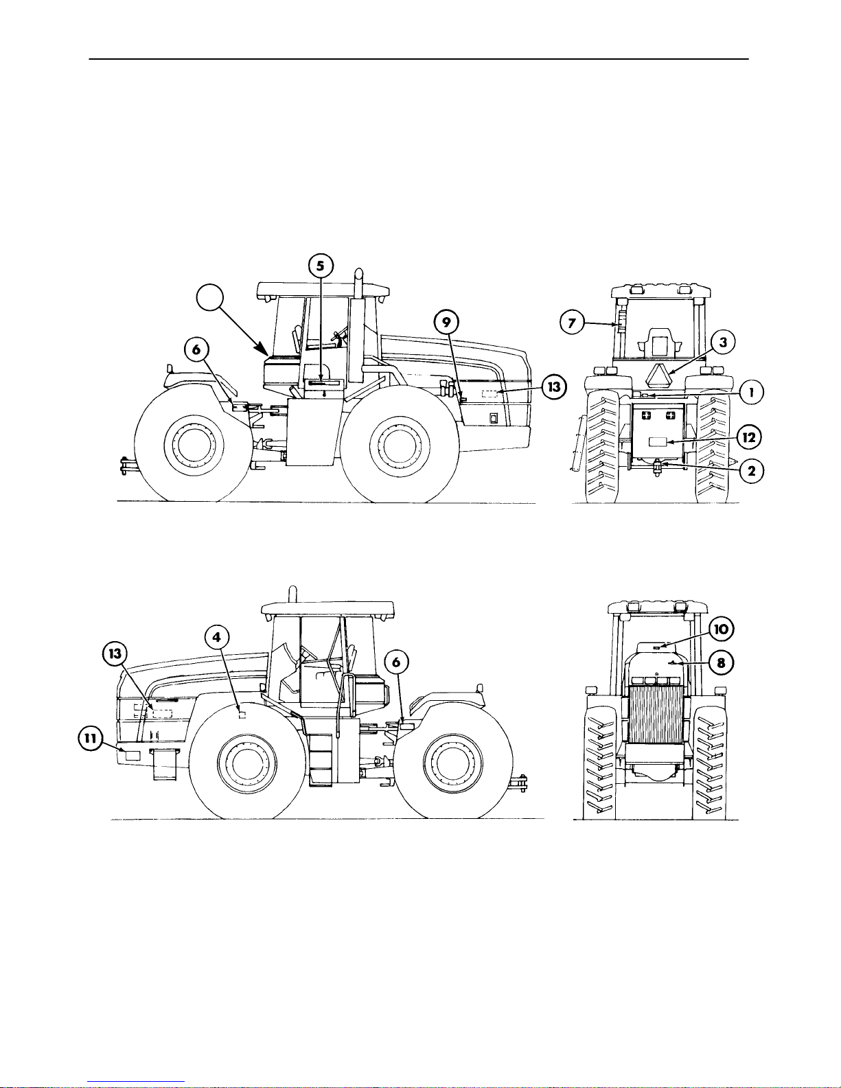
SAFETY DECALS
The following decals were installed on the tractor
in the areas indicated. They are intended for your
safety and for those working with you. Please
take this manual and walk around your tractor to
note the content and location of these decals.
14
Review these decals and the operating instructions detailed in this manual with themachine operators.
Keep the decals legible. If they are not, obtain replacements from your authorized dealer.
0-11
Page 14
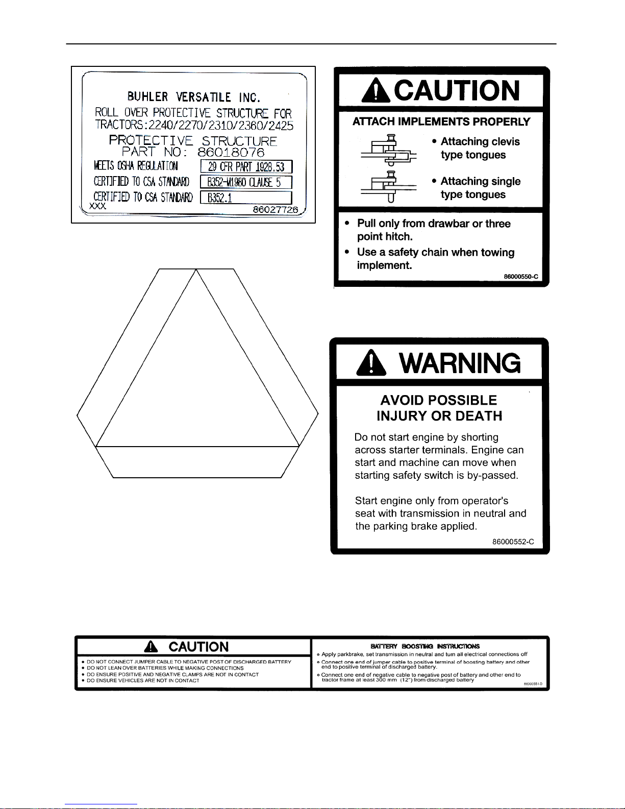
1. ROPS Certificate - Locatedrear left of cab.
3. Slow-Moving Vehicle - Located rear center
of tractor.
2. Implement Attaching - Located on the
drawbar at the rear of the tractor.
5. Battery Boosting - Located on the
4. Jump Starting - Located on the leftside of
the tractor on the starter.
underside of the battery cover.
0-12
Page 15
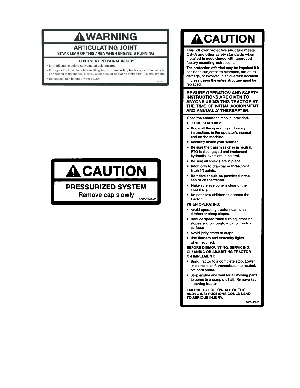
6. Pivoting Frames - Located on the right and left sides of
the rear frame in the articulation area.
8. Radiator Cap Pressure - Located on the
left side of the hood at the access hole for
the radiator cap.
86000553
7. ROPS Caution - Located inside
the cab on the rear left post.
0-13
Page 16
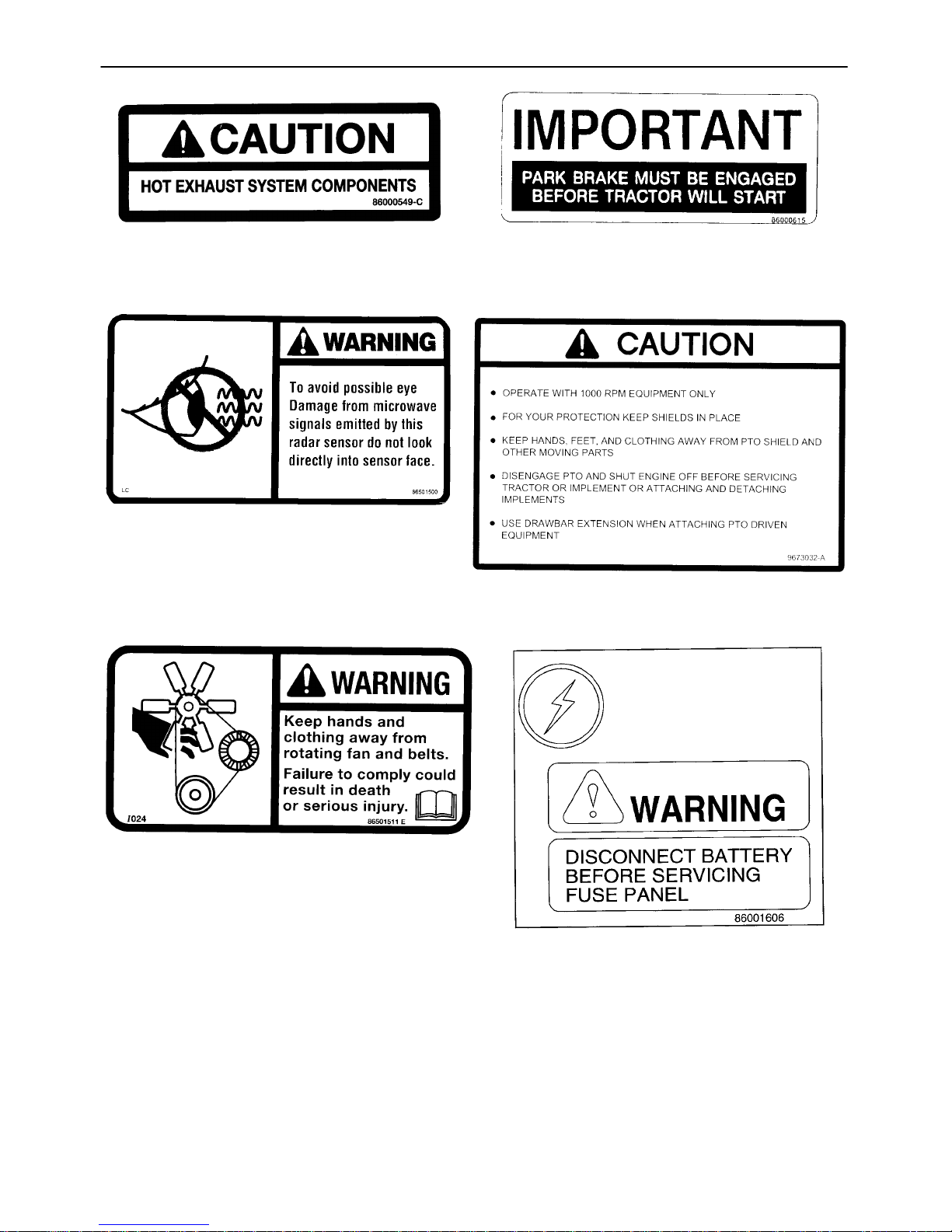
9. Hot Exhaust - Located on the right side
engine hood.
9702854
11. Ground Speed Radar - Located on the
front left side of the tractor.
10. Park Brake - Located in the front
windshield in the center.
12. PTO Safety - Located on top of the PTO
master shield.
13. Engine Cooling Fan - Located under the
engine side shields.
14. Fuse and Relay Panel - Located
on rear shelf of cab in panel
compartment.
0-14
Page 17
ADDITIONAL SAFETY ITEMS
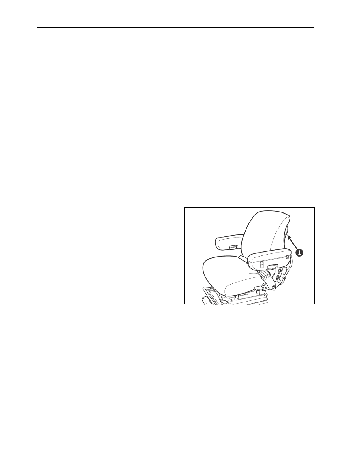
ARTICULATION LOCK
1. Use the articulation lock, 1, during stationary
applications, servicing, jacking or overhaul
operations. Do not use when the tractor is
operating.
2. Before engaging the lock, drive the tractor to a
level surface, put the steering straight,
engage the park brake, put the gearshift in
neutral and stop the engine.
1
3. Remove the pin from the storage position on
the swing frame right and put the pin through
theholeontheswingframeleft.
NOTE: It may be necessary to start the
engine and articulate the frame slightly to
be sure the articulation pin is positioned
properly and completely seated through
the frame pieces.
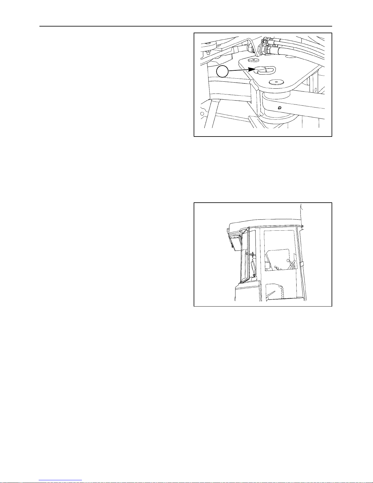
ALTERNATE EXIT
1. The cab has an emergency exit located in the
right rear of the cab. Pull the pin attaching the
lever to the glass window. This will allow the
window to open beyond the latch. If greater
access is required, thesilicone hinge/seal can
be sliced to remove the window completely.
19992745
Figure 0- 1
19992746
Figure 0- 2
0-15
Page 18

SAFETY CAB
A safety cab incorporating a Roll Over Protective
Structure (ROPS) and safety belt were standard
equipment for the tractor at time of factory assembly. The safety belt, when used by the operator,
maximizes the protection offered by the ROPS.
WARNING: ALWAYS USE YOUR SAFETY
BELT WITH THE CAB/ROPS TO PREVENT
BEING THROWN FROM THE TRACTOR IN
THE EVENT OF A ROLLOVER. SAFETY BELTS
SAVE LIVES WHEN THEY ARE USED.
Information regarding the safety cab/Roll Over
Protective Structure and safety belt are available
from your authorized Buhler Versatile dealer.
ROPS Maintenance and Inspection
After the first 50 hours of operation and every
1500 hours of operation (or yearly, whichever
comes first):
19992747
Figure 0- 3
1. Check the torque of the cab/ROPS mounting
bolts, as detailed in the lubrication and
maintenance section of this manual.
2. Check the operator’s seat mounting bolts and
the safety belt mounting bolts. Tighten the
seat mounting bolts to 40 N⋅m (30 ft. lbs.).
Replace any worn or damaged parts.
Damage to the Cab/ROPS
If the tractor has rolled over or the cab/ROPS has
been damaged (such as striking an overhead object during transport), it must be replaced to provide the original protection.
After an accident, check for damage to the cab/
ROPS, operator’s seat, safety belt and safety belt
mountings. Before you operate the tractor, replace all damaged parts.
0-16
Page 19

IMPORTANT: Do not try to weld or straighten the
cab/ROPS.
WARNING: NEVER ATTACH CHAINS, ROPES
OR CABLES TO THE CAB/ROPS FOR
PULLING PURPOSES. ALWAYS PULL FROM
THE TRACTOR DRAWBAR. BE CAREFUL
WHEN DRIVING THROUGH DOOR OPENINGS
OR UNDER LOW OVERHEAD OBJECTS.
MAKE SURE THERE IS SUFFICIENT
OVERHEAD CLEARANCE FOR THE
CAB/ROPS.
WARNING: IF THE CAB/ROPS IS REMOVED
OR REPLACED, MAKE CERTAIN THAT THE
PROPER HARDWARE IS USED AND THE
RECOMMENDED TORQUE VALUES ARE
APPLIED TO THE ATTACHING BOLTS. SEE
YOUR AUTHORIZED BUHLER VERSATILE
DEALER.
19992747
Figure 0- 4
0-17
Page 20

0-18
Page 21
SECTION 1
GENERAL INFORMATION
INTRODUCTION TO THIS MANUAL
This manual has been prepared to assist you in
the correct procedure for breaking in, driving,
operating, and maintaining your tractor.
The manual is divided into five sections as
detailed in the “Contents” page. An index is
provided at the back of the manual.
Read this manual carefully and keep it in the
manual holder attached totherear of the seat for
future reference. If at any time you require
advice concerning your tractor, do not hesitate
to contact your authorized Buhler Versatile
dealer. He has factory-trained personnel,
genuine replacement parts, and the necessary
equipment for your service requirements.
Your tractor has been designed and built to give
maximum performance, economy and ease of
operation under a wide variety of operating
conditions. Prior to delivery, the tractor was
carefully inspected, both at the factory and by
your dealer, to ensure that it reaches you in
optimum condition. To maintain this condition
and ensure trouble -free operation, it is
important that the routine services, as specified
in this manual, are carried out at the
recommended intervals.
The company policy i s one of continuous
improvement, and the right to change prices,
specifications or equipment at any time without
notice is reserved.
Section “0” of thismanuallists the precautions to
be observed to ensure your safety and the
safety of others. Read the safety precautions
carefully and follow the advice offered BEFORE
operating the tractor.
OPERATOR’S MANUAL HOLDER
A manual holder, 1, is attached to the rear of the
seat. Store the operator’s manual and other
tractor information in the holder.
All data given in this book is subject to
production variations. Dimensions and weights
are approximate only, and the illustrations do
not necessarily show tractors in standard
condition. For exact information about any
particular tractor, please consult your
authorized dealer.
Figure 1-1
1-1
Page 22

SECTION 1 - GENERAL INFORMATION
TRACTOR STATEMENT OF USE
Buhler Versatile has designed the 2290, 2335,
2360, 2375 and 2425 4WD articulated tractors
to be used in customary agricultural
applications. Using the tractor in an industrial
only application (ie. road building) will not be
covered by warranty.
The machine is constructed to use specific tire
combinations along with additional ballast to
properly distribute weight and power for the
operation of agricultural equipment.
To obtain maximum performance and durability,
the tractor must be operated and maintained in
a manner as described in this manual. Failure to
follow the information contained in this manual
may lead to premature deterioration or personal
injury.
You have made a substantial investment in this
agricultural tractor and it demands proper
operation and maintenance. PLEASE
FOLLOW YOUR OPERATOR’S MANUAL.
Thank you for purchasing your Buhler Versatile
tractor.
1-2
Page 23
SECTION 1 - GENERAL INFORMATION
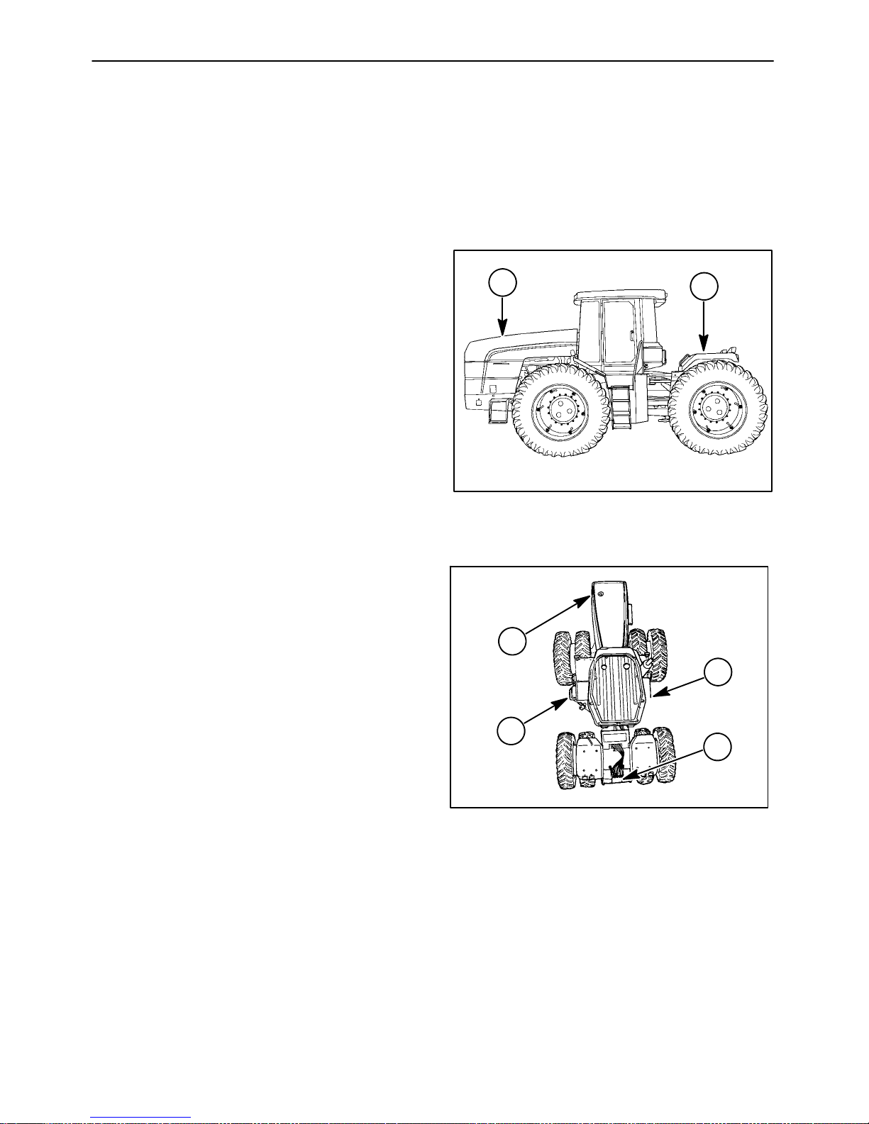
TRACTOR ORIENTATION
OVERALL DESCRIPTION
The Models 2290, 2335, 2360, 2375 and 2425
tractors are classified as 4 -wheel drive
articulating vehicles. The tractors consist of front
and rear frame assemblies which steer by
pivoting at the center articulation joint.
The front frame, 1, incorporates the engine, fuel
tanks, transmission, front drive axle, and cab.
The rear frame, 2, incorporates the rear drive
axle and supports any implements that are
operated by the tractor. This type of design
allows for greater flexibility of weight distribution,
depending upon operating conditions and typeof
implement. The operator can ballast the tractor
to best suit the needs of the particular operation.
The construction of the tractor is a modular-type
construction. This means that the major
components are individual units which are
supported within the front and rear frames. This
makes for easier serviceability and longer life
due to reduced structural stress on components.
1
2
Figure 1-2
TRACTOR TERMINOLOGY
This manual uses the following terms todescribe
tractor function and directional relationships:
Front, 1 - The engine end of the tractor. This
direction will also be referred to as “Forward
Direction of Travel.”
Right, 2 - The console side of the cab.
Back , 3 - The drawbar end of the tractor, which is
used for pulling implements.
Left, 4 - The doorway side of the cab.
1
2
4
3
Figure 1-3
1-3
Page 24
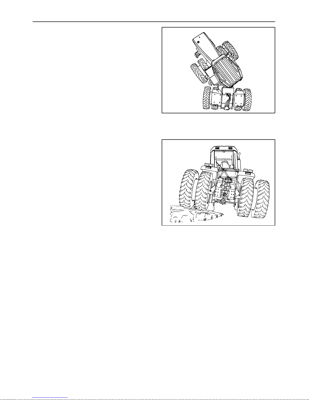
SECTION 1 - GENERAL INFORMATION
Articulation - The ability to steer by pivoting
between front and rear frame sections.
Oscillation - The ability of a vehicle to twist,
allowing travel over uneven terrain.
Figure 1-4
Figure 1-5
1-4
Page 25
SECTION 1 - GENERAL INFORMATION
IDENTIFICATION NUMBERS
TRACTOR IDENTIFICATION DATA
The tractor and its major components are
identified using serial numbers and/or
manufacturing codes. The following provides the
locations of the identification data.
NOTE: Tractor identification data must be
supplied to the dealer when requesting parts
or service.
Identification data is needed to aid in identifying
the tractor if it is ever stolen.
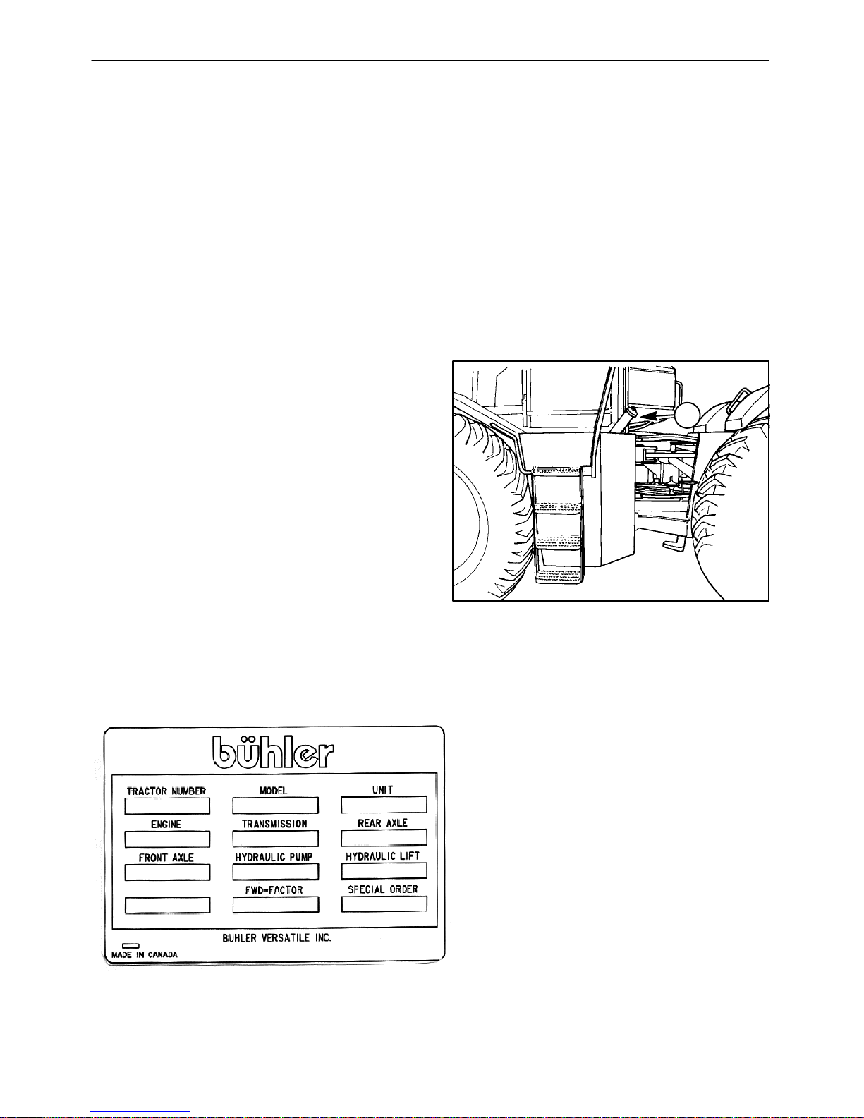
VEHICLE IDENTIFICATION PLATE
The vehicle identification plate is located on the
left rear corner, 1, of the cab.
1
Record the identification data in the sample ID plate.
Figure 1-6
1-5
Page 26
SECTION 1 - GENERAL INFORMATION
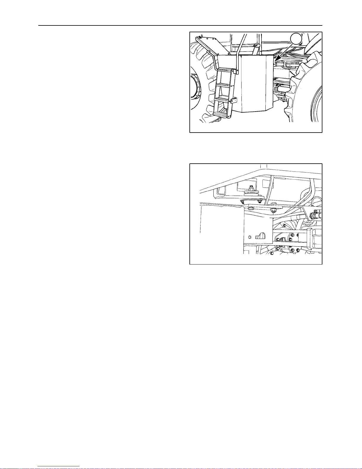
TRACTOR IDENTIFICATION
The serial number is stamped on the front frame
beside the left fuel tank, 1.
This serial number stamp is used in the event
that the Tractor Identification Plate is removed or
mutilated.
1
Figure 1-7
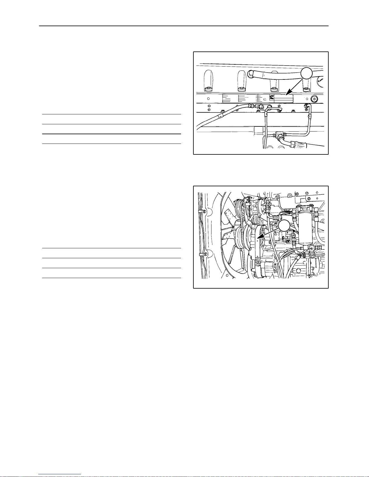
ENGINE IDENTIFICATION
The Cummins engine used in your Buhler
Versatile 4WD tractor is serviced solely by the
Cummins Engine Company through its
authorized dealers and distributors. For service,
warranty, and parts information, contact your
Buhler Versatile dealer. Many Buhler Versatile
dealers are authorized Cummins dealers. If your
dealer is not, he will arrange for the engine
service on your tractor by an authorized
Cummins engine dealer or distributor.
30XXXX
Figure 1-8
1-6
Page 27
SECTION 1 - GENERAL INFORMATION
For the 2290, 2335, 2375 tractor (Cummins
QSM11 engine), the Engine Identification Plate,
(1), is located on the left side of the engine block
below the valve cover.
Please record this information on the lines
provided.
For the 2360 and 2425 tractors (Cummins N14
engine), the Engine Identification Plate, 1, is
located on the left side of theengine ahead of the
fuel injection pump.
1
Figure 1-9
Please record this information on the lines
provided.
NOTE: It is very important to include the
engine number, engine family, and engine
CPL number (control parts listing) when
contact is made with a Cummins dealer or
distributor.
1
Figure 1-10
1-7
Page 28
SECTION 1 - GENERAL INFORMATION
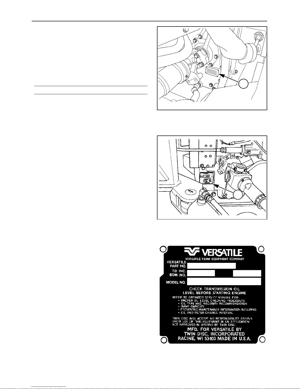
TRANSMISSION IDENTIFICATION
Quad Shift III Transmission
(12x4 Synchronized)
The serial number plate, 1, is on the right rear of
the transmission case. This is a 6-digit alpha
numeric number. Record this number on the line
provided.
Powershift Transmission (12x2 Powershift)
The serial number plate, 1, is located on the left
rear of the transmission housing.
1
Figure 1-11
The serial number plate contains information
that may be required for parts, service, or
warranty. Record the identification data in the
sample ID plate.
1
Figure 1-12
1-8
Page 29

SECTION 1 - GENERAL INFORMATION
FRONT AND REAR AXLE
IDENTIFICATION
On the underside (or topside) of the input shaft is
the Differential Identification Plate, 1, containing
Eaton differential model information. Record this
information on the lines provided.
NOTE: Make a copy of the information
recorded in the preceding paragraphs and
keep in a safe location in the event your
operator’s manual is lost or destroyed.
1
19988494
Figure 1-13
1-9
Page 30
SECTION 1 - GENERAL INFORMATION
PROTECTIVE SHIELDING
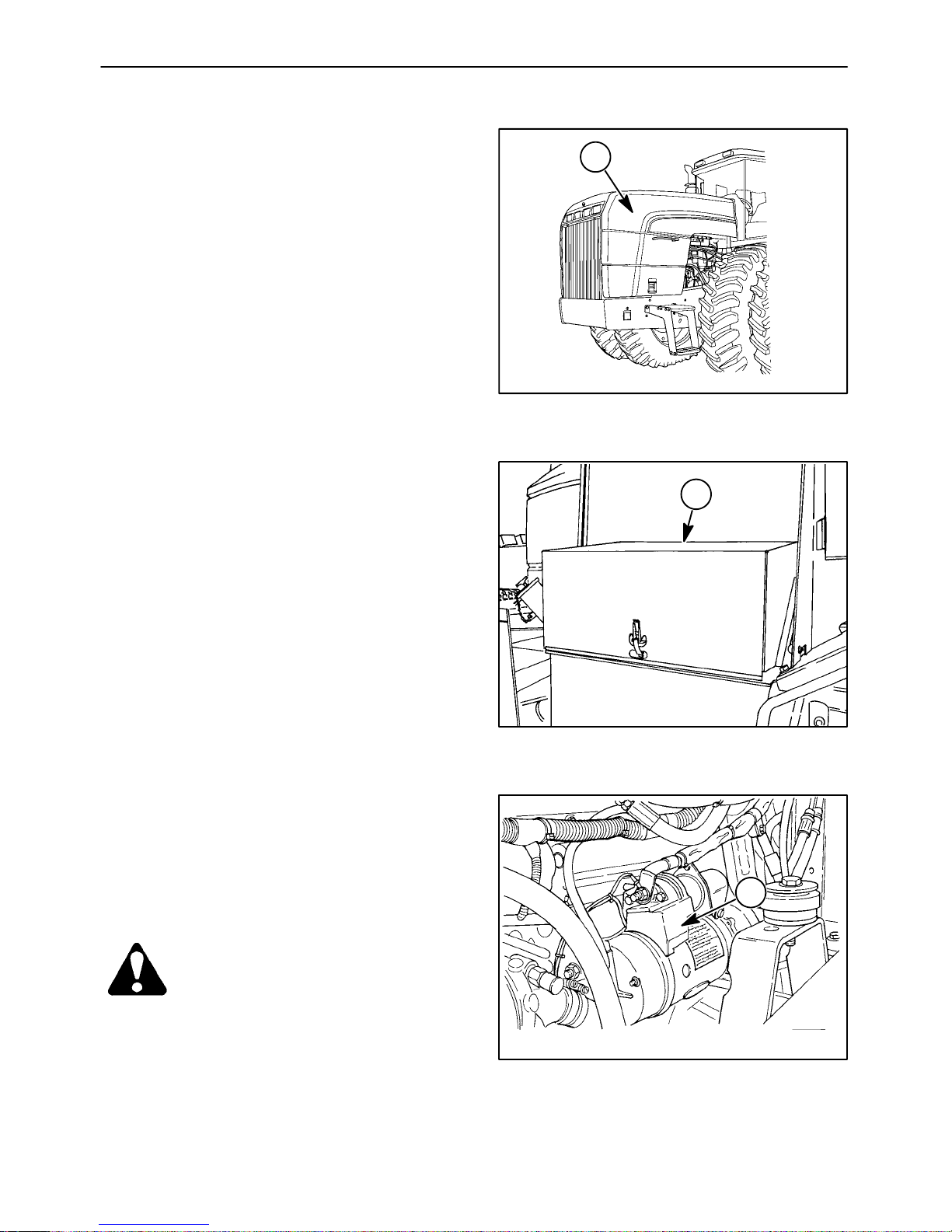
ENGINE SIDE COVERS
The side covers, 1, protect the operator from
heated and/or moving parts. Do not operate the
tractor without the engine side covers in place
and latched.
BATTERY COVER
The battery cover, 1, protects the batteries from
damage and the electrical connections from
accidental contact. The battery cover must
always be in place and latched during operation.
1
Figure 1-14
1
STARTER SOLENOID SHIELD
The shield, 1, covers the starter solenoid
electrical connections to prevent accidental
contact. The shield must be installed whenever
the batteries are connected to the electrical
system.
DANGER: NEVER ATTEMPT TO START THE
TRACTOR BY BYPASSING THE WIRES TO
THE STARTER MOTOR.
Figure 1-15
1
19992828
Figure 1-16
1-10
Page 31

SECTION 1 - GENERAL INFORMATION
MASTER PTO SHIELD
The shield, 1, covers the PTO stub shaft, if so
equipped. The shield does not pivot or lift up.
CAUTION: DO NOT REMOVE OR MODIFY
THE PTO SHIELD.
CENTER PTO ARTICULATION
DRIVE SHAFT SHIELD
The shield, 1, covers the PTO drive shaft, if so
equipped, as it passes through the articulation
area.
1
Figure 1-17
CAUTION: DO NOT REMOVE OR MODIFY
THE PTO SHIELD.
WARNING: INSTALL PROTECTIVE SHIELDS
BEFORE STARTING OR OPERATING THE
TRACTOR.
1
Figure 1-18
1-11
Page 32

SECTION 1 - GENERAL INFORMATION
TIRE CONFIGURATIONS
The 2290, 2335, 2360, 2375 and 2425 tractors are designed to be used with specific tire configurations
and should only be used with those tires approved for use on a specific model. The detailed charts on
the following pages give all tire configurations by model that can be used on a particular model tractor.
IF A SPECIFIC TIRE SIZE IS NOT LISTED UNDER THE MODEL TRACTOR YOU OWN, DO NOT
ATTEMPT TO INSTALL THAT SIZE OR CONFIGURATION OF TIRE.
ARTICULATION STOP SPACERS - QUICK REFERENCE CHART
BAND
DRUM DUAL
INNER
24.5x32 N/A N/A NONE NONE N/A
30.5x32 N/A N/A NONE 38_ N/A
18.4x38 NONE NONE NONE NONE N/A
20.8x38 NONE NONE NONE NONE N/A
18.4x42 38_ 38_ 38_ 38_ 31_
20.8x42 38_ 38_ 38_ 38_ 31_
18.4x46 38_ 38_ N/A N/A 31_
700/65x38 38_ 33_ N/A N/A N/A
710/70x38 38_ 33_ N/A N/A N/A
750/65x38 38_ 33_ N/A N/A N/A
850/60x38 31_ 31_ N/A N/A N/A
DRUM DUAL
OUTER
SPACER
DUAL INNER
BAND
SPACER
DUAL OUTER
DRUM DUAL
TRIPLE
1-12
Page 33

SECTION 1 - GENERAL INFORMATION
2290
TIRE SIZE CONFIGURATION RIM STYLE MAXIMUM
ARTICULATION
ANGLE (1)
24.5R32 RADIAL ** SINGLES TIE ROD 42°
20.8R38 R1W RADIAL SINGLES DRUM 42°
20.8R42 R1W RADIAL SINGLES DRUM 38°
30.5x32 R1 10 PLY SINGLES TIE ROD 38°
30.5x32 R2 10 PLY SINGLES TIE ROD 38°
710/70R38 RADIAL ** SINGLES DRUM 38°
710/70R38 R1W RADIAL SINGLES DRUM 38°
700/65x38 8 PLY SINGLES DRUM 38°
750/65R38 8 PLY SINGLES DRUM 38°
850/60R38 8 PLY SINGLES DRUM 31°
18.4x38 R1 6 PLY DUALS TIE ROD 42°
18.4x38 R2 6 PLY DUALS TIE ROD 42°
18.4R38 RADIAL * DUALS TIE ROD 42°
18.4x42 R1 8 PLY DUALS TIE ROD 42°
20.8x38 R1 8 PLY DUALS TIE ROD 42°
20.8x38 R2 8 PLY DUALS TIE ROD 42°
20.8R38 RADIAL * DUALS TIE ROD 42°
20.8R38 R1W RADIAL DUALS TIE ROD 42°
20.8x42 R1 10 PLY DUALS TIE ROD 38°
20.8R42 RADIAL ** DUALS TIE ROD 38°
20.8x42 R2 RADIAL DUALS TIE ROD 38°
20.8R42 R1W RADIAL DUALS TIE ROD 38°
24.5x32 R1 10 PLY DUALS TIE ROD 42°
24.5R32 RADIAL * DUALS TIE ROD 42°
30.5x32 R2 10 PLY DUALS TIE ROD 33°
30.5R32 R1 RADIAL DUALS TIE ROD 33°
18.4R46 RADIAL *** DUALS DRUM 38°
20.8R38 R1W RADIAL DUALS DRUM 42°
20.8x42 R1 8 PLY DUALS DRUM 38°
20.8R42 RADIAL ** DUALS DRUM 38°
20.8R42 R1W RADIAL DUALS DRUM 38°
20.8R42 R2 RADIAL DUALS DRUM 38°
700/65x38 8 PLY DUALS DRUM 33°
710/70R38 RADIAL ** DUALS DRUM 33°
710/70R38 R1W RADIAL DUALS DRUM 33°
750/65R38 8 PLY DUALS DRUM 33°
18.4x38 R1 8 PLY DUALS DRUM (30″) ROW CROP 42°
18.4R38 RADIAL * DUALS DRUM (30″) ROW CROP 42°
18.4x42 R1 10 PLY DUALS DRUM (30″) ROW CROP 38°
18.4R42 RADIAL ** DUALS DRUM (30″) ROW CROP 38°
18.4R46 RADIAL *** DUALS DRUM (30″) ROW CROP 38°
Radial tires are identified according to rating by a star code - either one star (*), two stars (**) or three stars (***).
(1) Any tractor that is equipped with a PTO option requires a 38° articulation block kit be installed on it . If the tire size of the
tractor requires a 33° or 31° articulation kit, use those kits instead of the 38° kit for a PTO option.
1-13
Page 34

SECTION 1 - GENERAL INFORMATION
2335
TIRE SIZE CONFIGURATION RIM STYLE MAXIMUM
ARTICULATION
ANGLE (1)
24.5R32 RADIAL ** SINGLES TIE ROD 42°
20.8R38 R1W RADIAL SINGLES DRUM 42°
20.8R42 R1W RADIAL SINGLES DRUM 38°
30.5x32 R1 10 PLY SINGLES TIE ROD 38°
30.5x32 R2 10 PLY SINGLES TIE ROD 38°
710/70R38 RADIAL ** SINGLES DRUM 38°
710/70R38 R1W RADIAL SINGLES DRUM 38°
700/65x38 8 PLY SINGLES DRUM 38°
750/65R38 8 PLY SINGLES DRUM 38°
850/60R38 8 PLY SINGLES DRUM 31°
18.4x38 R1 6 PLY DUALS TIE ROD 42°
18.4x38 R2 6 PLY DUALS TIE ROD 42°
18.4R38 RADIAL * DUALS TIE ROD 42°
18.4x42 R1 8 PLY DUALS TIE ROD 42°
20.8x38 R1 8 PLY DUALS TIE ROD 42°
20.8x38 R2 8 PLY DUALS TIE ROD 42°
20.8R38 RADIAL * DUALS TIE ROD 42°
20.8R38 R1W RADIAL DUALS TIE ROD 42°
20.8x42 R1 10 PLY DUALS TIE ROD 38°
20.8R42 RADIAL ** DUALS TIE ROD 38°
20.8x42 R2 RADIAL DUALS TIE ROD 38°
20.8R42 R1W RADIAL DUALS TIE ROD 38°
24.5x32 R1 10 PLY DUALS TIE ROD 42°
24.5R32 RADIAL * DUALS TIE ROD 42°
30.5x32 R2 10 PLY DUALS TIE ROD 33°
30.5R32 R1 RADIAL DUALS TIE ROD 33°
18.4R46 RADIAL *** DUALS DRUM 38°
20.8R38 R1W RADIAL DUALS DRUM 42°
20.8x42 R1 8 PLY DUALS DRUM 38°
20.8R42 RADIAL ** DUALS DRUM 38°
20.8R42 R1W RADIAL DUALS DRUM 38°
20.8R42 R2 RADIAL DUALS DRUM 38°
700/65x38 8 PLY DUALS DRUM 33°
710/70R38 RADIAL ** DUALS DRUM 33°
710/70R38 R1W RADIAL DUALS DRUM 33°
750/65R38 8 PLY DUALS DRUM 33°
18.4x38 R1 8 PLY DUALS DRUM (30″) ROW CROP 42°
18.4R38 RADIAL * DUALS DRUM (30″) ROW CROP 42°
18.4x42 R1 10 PLY DUALS DRUM (30″) ROW CROP 38°
18.4R42 RADIAL ** DUALS DRUM (30″) ROW CROP 38°
18.4R46 RADIAL *** DUALS DRUM (30″) ROW CROP 38°
Radial tires are identified according to rating by a star code - either one star (*), two stars (**) or three stars (***).
(1) Any tractor that is equipped with a PTO option requires a 38° articulation block kit be installed on it . If the tire size of the
tractor requires a 33° or 31° articulation kit, use those kits instead of the 38° kit for a PTO option.
1-14
Page 35

SECTION 1 - GENERAL INFORMATION
2360
TIRE SIZE CONFIGURATION RIM STYLE MAXIMUM
ARTICULATION
ANGLE (1)
24.5R32 RADIAL * SINGLES TIE ROD 42°
20.8R38 R1W RADIAL SINGLES DRUM 42°
20.8R42 R1W RADIAL SINGLES DRUM 38°
30.5x32 R2 10 PLY SINGLES TIE ROD 38°
710/70R38 RADIAL ** SINGLES DRUM 38°
710/70R38 R1W RADIAL SINGLES DRUM 38°
700/65 x 38 8 PLY SINGLES DRUM 38°
750/65R38 8 PLY SINGLES DRUM 38°
850/60R38 8 PLY SINGLES DRUM 31°
20.8x38 R2 8 PLY DUALS TIE ROD 42°
20.8R38 R1W RADIAL DUALS TIE ROD 42°
20.8x42 R1 10 PLY DUALS TIE ROD 38°
20.8R42 RADIAL ** DUALS TIE ROD 38°
20.8R42 R2 RADIAL DUALS TIE ROD 38°
20.8R42 R1W RADIAL DUALS TIE ROD 38°
24.5x32 R1 10 PLY DUALS TIE ROD 42°
24.5R32 RADIAL * DUALS TIE ROD 42°
30.5x32 R2 10 PLY DUALS TIE ROD 33°
30.5R32 R1 RADIAL DUALS TIE ROD 33°
18.4R46 RADIAL *** DUALS DRUM 38°
20.8R38 R1W RADIAL DUALS DRUM 42°
20.8x42 R1 8 PLY DUALS DRUM 38°
20.8R42 RADIAL ** DUALS DRUM 38°
20.8R42 R2 RADIAL DUALS DRUM 38°
20.8R42 R1W RADIAL DUALS DRUM 38°
700/65x38 8 PLY DUALS DRUM 33°
710/70R38 RADIAL ** DUALS DRUM 33°
750/65R38 8 PLY DUALS DRUM 33°
850/65R38 8 PLY DUALS DRUM 31°
18.4R46 RADIAL *** DUALS DRUM (30″) ROW CROP 38°
18.4R46 R1 RADIAL TRIPLES ⊗ DRUM 31°
20.8x42 R1 8 PLY TRIPLES ⊗ DRUM 31°
20.8R42 RADIAL ** TRIPLES ⊗ DRUM 31°
20.8R42 R2 RADIAL TRIPLES ⊗ DRUM 31°
Radial tires are identified according to rating by a star code - either one star (*), two stars (**) or three stars (***).
⊗ - Triple tires mounted on the 2360 only when the tractor is equipped with heavy-duty axles.
(1) Any tractor that is equipped with a PTO option requires a 38° articulation block kit be installed on it . If the tire size of the
tractor requires a 33° or 31° articulation kit, use those kits instead of the 38° kit for a PTO option.
1-15
Page 36

SECTION 1 - GENERAL INFORMATION
2375
TIRE SIZE CONFIGURATION RIM STYLE MAXIMUM
ARTICULATION
ANGLE (1)
24.5R32 RADIAL * SINGLES TIE ROD 42°
20.8R38 R1W RADIAL SINGLES DRUM 42°
20.8R42 R1W RADIAL SINGLES DRUM 38°
30.5x32 R2 10 PLY SINGLES TIE ROD 38°
710/70R38 RADIAL ** SINGLES DRUM 38°
710/70R38 R1W RADIAL SINGLES DRUM 38°
700/65 x 38 8 PLY SINGLES DRUM 38°
750/65R38 8 PLY SINGLES DRUM 38°
850/60R38 8 PLY SINGLES DRUM 31°
20.8x38 R2 8 PLY DUALS TIE ROD 42°
20.8R38 R1W RADIAL DUALS TIE ROD 42°
20.8x42 R1 10 PLY DUALS TIE ROD 38°
20.8R42 RADIAL ** DUALS TIE ROD 38°
20.8R42 R2 RADIAL DUALS TIE ROD 38°
20.8R42 R1W RADIAL DUALS TIE ROD 38°
24.5x32 R1 10 PLY DUALS TIE ROD 42°
24.5R32 RADIAL * DUALS TIE ROD 42°
30.5x32 R2 10 PLY DUALS TIE ROD 33°
30.5R32 R1 RADIAL DUALS TIE ROD 33°
18.4R46 RADIAL *** DUALS DRUM 38°
20.8R38 R1W RADIAL DUALS DRUM 42°
20.8x42 R1 8 PLY DUALS DRUM 38°
20.8R42 RADIAL ** DUALS DRUM 38°
20.8R42 R2 RADIAL DUALS DRUM 38°
20.8R42 R1W RADIAL DUALS DRUM 38°
700/65x38 8 PLY DUALS DRUM 33°
710/70R38 RADIAL ** DUALS DRUM 33°
750/65R38 8 PLY DUALS DRUM 33°
850/65R38 8 PLY DUALS DRUM 31°
18.4R46 RADIAL *** DUALS DRUM (30″) ROW CROP 38°
18.4R46 R1 RADIAL TRIPLES ⊗ DRUM 31°
20.8x42 R1 8 PLY TRIPLES ⊗ DRUM 31°
20.8R42 RADIAL ** TRIPLES ⊗ DRUM 31°
20.8R42 R2 RADIAL TRIPLES ⊗ DRUM 31°
Radial tires are identified according to rating by a star code - either one star (*), two stars (**) or three stars (***).
⊗ - Triple tires mounted on the 2375 only when the tractor is equipped with heavy-duty axles.
(1) Any tractor that is equipped with a PTO option requires a 38° articulation block kit be installed on it . If the tire size of the
tractor requires a 33° or 31° articulation kit, use those kits instead of the 38° kit for a PTO option.
1-16
Page 37

SECTION 1 - GENERAL INFORMATION
2425
TIRE SIZE CONFIGURATION RIM STYLE MAXIMUM
ARTICULATION
ANGLE (1)
20.8R38 R1W RADIAL SINGLES DRUM 42°
20.8R42 R1W RADIAL SINGLES DRUM 38°
30.5x32 R2 10 PLY SINGLES TIE ROD 38°
710/70R38 RADIAL ** SINGLES DRUM 38°
710/70R38 R1W RADIAL SINGLES DRUM 38°
700/65x38 8 PLY SINGLES DRUM 38°
750/65R38 8 PLY SINGLES DRUM 38°
850/60R38 8 PLY SINGLES DRUM 31°
20.8x38 R2 8 PLY DUALS TIE ROD 42°
20.8R38 R1W RADIAL DUALS TIE ROD 42°
20.8x42 R1 10 PLY DUALS TIE ROD 38°
20.8R42 RADIAL ** DUALS TIE ROD 38°
20.8R42 R2 RADIAL DUALS TIE ROD 38°
20.8R42 R1W RADIAL DUALS TIE ROD 38°
24.5x32 R1 10 PLY DUALS TIE ROD 42°
24.5R32 RADIAL * DUALS TIE ROD 42°
30.5x32 R2 10 PLY DUALS TIE ROD 33°
30.5R32 R1 RADIAL DUALS TIE ROD 33°
20.8R38 R1W RADIAL DUALS DRUM 42°
20.8x42 R1 10 PLY DUALS DRUM 38°
20.8R42 RADIAL ** DUALS DRUM 38°
20.8R42 R2 RADIAL DUALS DRUM 38°
20.8R42 R1W RADIAL DUALS DRUM 38°
700/65x38 8 PLY DUALS DRUM 33°
710/70R38 RADIAL ** DUALS DRUM 33°
750/65R38 8 PLY DUALS DRUM 33°
850/65R38 8 PLY DUALS DRUM 31°
18.4R46 RADIAL *** DUALS DRUM (30″) ROW CROP 38°
18.4R46 R1 RADIAL TRIPLES DRUM 31°
20.8x42 R1 10 PLY TRIPLES DRUM 31°
20.8R42 RADIAL ** TRIPLES DRUM 31°
20.8R42 R2 RADIAL TRIPLES DRUM 31°
Radial tires are identified according to rating by a star code - either one star (*), two stars (**) or three stars (***).
(1) Any tractor that is equipped with a PTO option requires a 38° articulation block kit be installed on it . If the tire size of the
tractor requires a 33° or 31° articulation kit, use those kits instead of the 38° kit for a PTO option.
1-17
Page 38

SECTION 1 - GENERAL INFORMATION
EXTERNAL LIGHTING
Your tractor is equipped with lights to allow for
nighttime and low light operation.
Front lighting consists of four worklamps, 1,
above the grille, one worklamp, 2, on each front
fender and two safety flashers, 3, at the top of the
cab.
Rear lighting consists of two worklamps, 1,
located on each rear fender. A combination
brake, turn and taillight, 2, is located in the rear
fenders and amber safety flashers, 3, are
mounted on the cab as standard equipment.
3
1
2
Figure 1-19
3
1
2
Wide transport marker lights are standard
equipment on all tractors. These are adjustable
to indicate the full width of the tires.
Figure 1-20
Figure 1-21
1-18
Page 39

SECTION 1 - GENERAL INFORMATION
Optional high mount worklamps, 1, for mounting
on top of the cab can be purchased from your
local Buhler Versatile dealer.
1
Figure 1-22
1-19
Page 40

SECTION 1 - GENERAL INFORMATION
CONTROLS AND INSTRUMENTS -
OVERVIEW OF LOCATION AND FUNCTION
The information on the following pages
identifies, locates and briefly describes the
function of the controls and instruments located
in the cab.
The controls have been divided into the
following six areas:
1. Forward operator controls
2. Foot and floor controls
3. Overhead controls
4. Right side console controls
5. Additional cab controls
6. Operator seat controls
IMPORTANT: The following information in this
section provides a general overview of location
of the controls, but does not provide detailed
operational information. Thoroughly read
Section 2 -“Operation” for details on how to use
the controls and read the instruments before
operating the tractor.
WARNING: DO NOT OPERATE THE
TRACTOR UNTIL YOU ARE THOROUGHLY
FAMILIAR WITH THE LOCATION AND
OPERATION OF ALL CONTROLS.
1-20
Page 41

SECTION 1 - GENERAL INFORMATION
FORWARD OPERATOR CONTROLS
1 Electronic monitor digit select switch
2 Instrument cluster
3 Engine oil pressure gauge
4 Electronic monitor
5 Engine water temperature gauge
6 Warning light bar
7 Electronic monitor acknowledge/reset button
8 Electronic monitor rotary select switch
9 Radio (if equipped)
10 Ignition switch
11 Steering wheel tilt control lever
12 Ether start button
13 Ashtray
14 Combination horn, turn signal and
headlight dimmer switch lever
18
15
14
1
13
2
3
4
5
6
7
8
16
9
17
11
10
12
Figure 1-23
15 Front windshield wiper switch
16 Rear window wiper switch
17 Front and rear windshield washer switch
18 Rotary light switch
Steering wheel (removed in figure)
Steering wheel height control knob
(removed in figure)
1-21
Page 42

SECTION 1 - GENERAL INFORMATION
FOOT AND FLOOR CONTROLS
1 Clutch control pedal
2 Brake pedal
3 Decelerator pedal
OVERHEAD CONTROLS
1 Air duct
2
1
3
Figure 1-24
2
3
5
7
2 Speaker (2)
3 Air conditioner on/off switch
4 Fan rotary select switch
5 Temperature control rotary select switch
6 Recirculation baffle rotary control
7 Recirculation vent (2)
8 Auxiliary three-pin connector
9 Rearview mirror
1
4
6
8
9
Figure 1-25
1-22
Page 43

SECTION 1 - GENERAL INFORMATION
RIGHT SIDE CONSOLE CONTROLS
1 Transmission shift levers - 12x4
Quad Shift III*
2 Speed chart
3 Flow control knob - grey circuit only
4 Tractor Performance Monitor (if equipped)
5 Cup holder
6 Remote valve control levers
7 PTO switch (optional)
8 Differential lock switch (optional)
9 Three-point hitch switch (optional)
10 Throttle control lever
11 Flow control knobs - blue, tan, and green
circuits
12 Cigarette lighter
13 Cruise control on/off switch
10
4
1
2
6
3
12
11
7
8
13
14
9
5
Figure 1-26
14 Cruise control +/-- switch
* See the following pages for powershift
transmission control lever.
ADDITIONAL CAB CONTROLS
Fuel Gauge - Mounted on the right-hand front
pillar of the cab.
Figure 1-27
1-23
Page 44

SECTION 1 - GENERAL INFORMATION
Liquid Crystal Display Readout - Powershift
Tractors Only - Mounted above the fuel gauge.
Electrical Control Panel - Directly behind the
operator’s seat, right-hand corner of the cab.
Figure 1-28
Dome Light and Coat Hook
Figure 1-29
Figure 1-30
1-24
Page 45

SECTION 1 - GENERAL INFORMATION
Console Light - The console light, 1, is mounted
in the front right-hand cab post directly below the
fuel gauge.
Powershift Transmission Control Lever, 1 Powershift Transmissions Only
1
Figure 1-31
1
Three-Point Hitch Controls - Optional - Located
on the right-hand console.
Figure 1-32
Figure 1-33
1-25
Page 46

SECTION 1 - GENERAL INFORMATION
Trouble Light - Mounted in the lower left rear
corner of the cab under the rear shelf.
Side Window - Right-hand rear window of the
cab. The only window that swings outward from
the cab.
Figure 1-34
Figure 1-35
1-26
Page 47

SECTION 1 - GENERAL INFORMATION
OPERATOR SEAT CONTROLS
The seat control levers s hown in this figure are:
1 Right-hand armrest height adjustment
2 Left-hand armrest height adjustment
3 Seat belt buckle
4 Fore and aft adjustment
5 Seat belt retractor
6 Air ride position control switch
The seat control levers s hown in this figure are:
1 Lumbar control knob
2 Backrest position control lever
3 Fore and aft isolation lever
4 Lateral isolation lever
2
6
3
1
5
4
Figure 1-36
1
2
5 Damping knob
6 Seat swivel control lever
3
4
6
5
Figure 1-37
1-27
Page 48

SECTION 1 - GENERAL INFORMATION
INSTALLATION OF CAB-MOUNTED ACCESSORIES
IMPLEMENT MONITOR BOXES,
GAUGES, CB RADIO, AND CELLULAR
PHONE
1. The cab has convenient mounting hardware,
1, located on the cab pillars to attach brackets
for monitor boxes, radios, or phones to be
placed near the operator.
A bracket P/N 86029617, 1, can be
purchased to aid in the installation of a
monitor on the cab pillar.
1
Figure 1-38
A bracket -- monitor/powerbar P/N 86031182,
2, can be purchased to aid in the installation of
a monitor and/or power bar on the cab pillar.
This powerbar includes a harness, 1, for
monitor power. The harness includes: 1
Cigarette Type Receptacle, 3, and 2 3-Pin
Auxiliary Connectors, 4.
1--KeySwitchPower--30Amp
2--LiveBatteryPower--15Amp
3 -- Ground
1
Figure 1-39
**
2
3
4
*
3
1
1
2
Figure 1-40
1-28
Page 49

SECTION 1 - GENERAL INFORMATION
Some monitors require a true ground speed
signal from a radar unit to be fed into them for
proper operation.
Buhler Versatile 4WD tractors equipped with
a Tractor Performance Monitor (TPM) option
can provide this signal to the monitor by
tapping into the existing wire harness on the
tractor.
To tap into the existing signal wire on the
tractor, use the following procedure:
a. Remove the cover from the rear of the
TPM module on the right-hand console.
The cover, 1, is held in position with velcro.
b. Pull out wire harness, 1, that is tucked into
the rear of the TPM.
c. The TPM is connected to the main cab wire
harness with a green 8-pin connector.
Locate the gray wire marked “CM-90” that
is plugged into the connector.
Figure 1-41
1
Wire “CM-90” is a processed 5-volt signal
that supplies the TPM with a 58.9 Hz/mph
output from the Electronic Instrument
Control System monitor
d. Using a pigtail-type splice connector, tie
into the “CM-90” wire with the wire leading
into the implement monitor.
The monitor will now receive a signal from
the radar unit at the front of the tractor.
e. Route the signal wire along the right-hand
console and out to the implement monitor.
f. Reinstall the TPM wire harness and
connect back into place and install the
TPM backplate.
Figure 1-42
1-29
Page 50

SECTION 1 - GENERAL INFORMATION
2. There are also four mounting bolt locations
directly above the dash so that a “Heads Up”
type monitor could also be located in front of
the operator.
3. The cab has a three-pin auxiliary connector,
1, located at the top of the right rear cab pillar
inside the cab.
Figure 1-43
1
4. The three-pin auxiliary connector has three
terminals inside of it. Pin, 1, is a switched
12-volt power source protected by a 20-amp
fuse. Pin 2 is an unswitched (live) 12-volt
power source protected by a 20-amp fuse.
The third pin, 3, is a ground pin.
Figure 1-44
3
1
2
Figure 1-45
1-30
Page 51

SECTION 1 - GENERAL INFORMATION
Buhler Versatile has a male connector, 1, that
will plug into the three-pin auxiliary connector.
It is available from your local Buhler Versatile
dealer using part #86032122. This number
will contain all parts necessary to install the
male connector. Please contact your Buhler
Versatile dealer for assistance in assembling
the connector. A special tool is required to
crimp the pins in the kit.
5. There is a secondary power source located
on a four-pin bus bar behind the cowling that
secures the fuel gauge.To access the four-pin
bus bar, remove the four cap screws, 1, that
secure the panel to the cab post.
1
Figure 1-46
NOTE: The power source pins are
protected by a 10-amp and 3-amp fuse,
respectively. The pins may not be suitable
for use with an implement monitor (due to
electrical load the monitor requires) and
are intended for use with additional
gauges installed by the operator. It is
suggested that the 3-pin auxiliary
connector be used to power the monitor.
1
Figure 1-47
1-31
Page 52

SECTION 1 - GENERAL INFORMATION
The bus bar pins are identified as follows:
Pin 1 is a switched 12-volt power source
that is live when the ignition is in the “RUN”
position (10-amp circuit protection).
Pin 2 is a switched 12-volt power source
that is live when the rotary light switch is in
the roadway or field use positions (3-amp
circuit protection).
Pin 3 is a ground pin.
Pin 4 is a secondary source for external
signals to access the external alarm
control of the Electronic Instrument
Control System.
For more information on how to hook up the
external alarm control, see the “Electronic
Instrument Control System” section of this
manual.
NOTE: The cowling that secures the bus
bar and fuel gauge has circular scribe
marks that can be cut out for installing
additional gauges. The scribe marks are
sized to standard size gauges.
34
2
1
Figure 1-48
6. To route umbilical cords to a monitor box,
remove the cover plate, 1, on the underside of
the right rear corner of the cab and route the
cord up into the cab.
1
Figure 1-49
1-32
Page 53

SECTION 1 - GENERAL INFORMATION
The rear shield, 1, in the back of the cab can
be removed by loosening the twowing nuts, 2,
and pulling the shield away from the rear wall
of the cab. Once the shield is removed, the
umbilical cord can be routed to the monitor
box.
1
2
2
Figure 1-50
7. Antennas for CB radios and cellular phones
can be installed in theroof cap, 1. These items
should be of such quality that they are
shielded to prevent interference with tractor
controls and instruments. Consult the radio or
phone manufacturer for proper antenna
installation.
The roof cap has additional antenna mounts
under the right-hand and left-hand rear corner
of the roof panel. These mounts can be used
by the operator for additional electrical
devices that require an antenna be mounted
on the tractor.
The roof cap also has two flat mounting
locations on top for mounting rotary style
beacons.
1
Figure 1-51
1-33
Page 54

SECTION 1 - GENERAL INFORMATION
WELDING & BATTERY CHARGING
PRECAUTIONS: WELDING
To avoid damage to the electronic/electrical
systems, always observe the following:
1. Always disconnect the ground cablefromthe
batteries before carrying out arc welding on
the tractor or on any implement attached to
the tractor.
2. Position the welder ground cable clamp as
close to the welding area as possible. Never
weld on one frame member (i.e., front or rear
frame) and have the ground strap of the
welder on the other frame. Doing this can
cause damage to the hoses, articulation
bearings, and wire harnesses in the
articulation joint area.
3. Never allow welding cables to lay on, near or
across any electrical wiring or electronic
component while welding is in progress.
4. On powershift transmission equipped units,
remove the electrical connectors attached to
the transmission electronic controller, even
when the negative cable of the battery is
disconnected, to provide additional
protection to the transmission controller.
5. Always have an assistant standing by with a
fire extinguisher to put out any fires that may
start due to welding procedures.
6. Always completely clean the area to be
welded so that it is free of any grease, fuel or
oil before welding.
PRECAUTIONS: BATTERY CHARGING
1. Never make or break any of the charging
circuit connections, including the connection
at the batteries, when the engine is running.
2. Never short any of the charging components
to ground.
3. Do not use a booster battery of higher than
12 volts nominal voltage.
4. Always observe correct polarity when
installing the batteries or using a booster
battery to jump start the engine. Follow the
instructions in this manual when jump
starting the tractor. Connect positive to
positive and negative to negative.
5. Always disconnect the negative cable from
the batteries when charging the batteries in
the tractor with a battery charger.
WARNING: BATTERIES CONTAIN SULFURIC
ACID. IN CASE OF CONTACT WITH SKIN,
FLUSH THE AFFECTED AREA WITH WATER
FOR FIVE MINUTES. SEEK MEDICAL
ATTENTION IMMEDIATELY.
AVOID CONTACT WITH THE SKIN, EYES OR
CLOTHING. WEAR EYE PROTECTION WHEN
WORKING NEAR BATTERIES.
1-34
Page 55

SECTION 1 - GENERAL INFORMATION
TOWING THE TRACTOR
IMPORTANT: The tractor should only be towed
a short distance, such as out of a building. Do
not tow down roadways or as a method of
transport. Haul the tractor on a trailer or truck for
transport.
Use a strong chain if towing the tractor is
necessary. Tow the tractor BACKWARD from
the drawbar or FORWARD from the axle. Use
the tie-down slots in the front and rear frames to
attach the chains to the tractor.
IMPORTANT: Do not tow the tractor by hooking
to the engine cross brace.
1. Place the transmission in neutral and engage
the park brake. Attach thec hain to the tractor.
2. If possible start the engine and let the engine
run so that full use can be made of the power
steering. If the engine cannot be run, engage
the articulation lock.
If the engine is not operational, and the
transmission internal components are
rotated by the axle drive shafts for a long
period of time, possible transmission
damage due to lack of lubrication may
result.
IMPORTANT: When the engine is running,
the clutch, transmission input shaft, and
transmission output shafts will also be
driven. Be sure that these components are
functional prior to starting the engine.
3. Release the park brake and tow the tractor.
WARNING: IF BOTH DRIVE SHAFTS TO
BOTH AXLES ARE DISCONNECTED AT
THE SAME TIME THERE WILL BE NO
BRAKES ON THE TRACTOR AND A
POSSIBLE COLLISION MAY RESULT.
If the transmission has failed and it is
necessary to disconnect the drive shafts
between the transmission and both the front
and rear axle, a solid towing bar must be
hooked between the tractor drawbar and the
towing vehicle. The towing vehicle must be of
adequate size to stop the towed tractor.
CAUTION: DO NOT TOW THE TRACTOR
FASTER THAN 8 KPH (5 MPH). ENGAGETHE
ARTICULATION LOCK WHEN IT IS NOT
POSSIBLE TO STEER THE TRACTOR (WITH
THE ENGINE RUNNING).
WARNING: DO NOT USE CABLES OR ROPE
TO TOW THE TRACTOR. IF THE CABLE OR
ROPE BREAKS OR SLIPS, IT MAY WHIP
WITH SUFFICIENT FORCE TO CAUSE
SERIOUS INJURY. WHEN USING A CHAIN,
ATTACH WITH THE HOOK OPEN SIDE
FACING UP; IF IT SLIPS, IT WILL DROP
DOWN INSTEAD OF FLYING UP AND
CAUSING SERIOUS INJURY.
4. If a failure has occurred in the front axle,
disconnect the drive shaft from the
transmission to the front axle only. Do not
disconnect the drive shaft between the
transmission and the rear axle.
1-35
Page 56

SECTION 1 - GENERAL INFORMATION
HAULING THE TRACTOR ON A TRANSPORTER
1. Haul the tractor with all four wheels on a
flatbed trailer or truck.
2. Remove the outer duals or triples during
hauling unless special permits allow for
over-width hauling. Consult local authorities
for information on over-width hauling.
3. Make an accurate measurement of the
highest point on the tractor when it is on the
flatbed of the truck. Consult local authorities
regarding over height hauling based on the
measurement taken.
4. Tie-down brackets are located on either side
of the drawbar cage, 1, to allow a chain of
adequate size to be routed through the
brackets and hold down the rear end of the
tractor.
5. There are cutout slots, 1, on either side of the
front frame of the tractor to allow a chain hook
to fasten the front end of the tractor down.
6. Always install the articulation lock pin and set
the park brake while transporting the vehicle.
1
Figure 1-52
1
Figure 1-53
1-36
Page 57

SECTION 1 - GENERAL INFORMATION
PRE-OPERATION CHECKS
Before operating the tractor, be sure you are
thoroughly familiar with the location and
operation of the controls.
Perform all daily lubrication and maintenance
operations as outlined in Section 3.
After completing the daily maintenance
operations, perform a walk around visual
inspection of the tractor. Pay particular attention
to the following items:
D Fan belt for cracks
D Engine area for accumulation of debris
D Hoses, lines, and fittings for leaks or
damage.
D Tires for damage
D Hardware for looseness
D Driveline and hydraulic pump areas for
leaks or debris accumulation
D Make sure the tractor is ballasted properly
for the work to be performed (see
“Ballasting” in Section 2)
D Check dual or triple wheel mounting bolt
torque
Make any necessary repairs before using the
tractor.
1-37
Page 58

SECTION 1 - GENERAL INFORMATION
1-38
Page 59

SECTION 2
OPERATION
INTRODUCTION
Read this section thoroughly. It details the
location and operation of the various
instruments, switches and controls on your
tractor. Even if you operate other tractors, you
should thoroughly read this section of the
manual and be sure that you are familiar with the
location and function of all the features of the
tractor.
Do not start the engine or attempt to drive or
operate the tractor until you are fully
accustomed to all the controls. It is too late to
learn after the tractor is moving. If in doubt about
any aspect of operation of the tractor, consult
your authorized dealer.
Pay particular attention to the break-in
recommendations to ensure that your tractor
will give the long and dependable service for
which it was designed.
See Section 3 for lubrication and maintenance
requirements. Tractorspecifications are listed in
Section 5.
2-1
Page 60

SECTION 2 - OPERATION
PRECAUTIONARY STATEMENTS
CAUTION: DO NOT OPERATE THE
TRACTOR IN A CLOSED BUILDING.
BEFORE STARTING THE ENGINE, BE SURE
ALL OPERATING CONTROLS ARE IN
NEUTRAL OR OFF AND THE PARK BRAKE
IS ENGAGED.
OPERATE ALL CONTROLS ONLY FROM
THE OPERATOR’S SEAT.
STOP THE ENGINE BEFORE SERVICING
THE TRACTOR.
KEEP ALL SHIELDS IN PLACE.
STOP THE ENGINE BEFORE RAISING THE
ENGINE SIDE SHIELDS.
USE HANDHOLDS AND STEPS WHEN
MOUNTING AND DISMOUNTING THE
TRACTOR.
USE THE ARTICULATION LOCK IN
STATIONARY APPLICATIONS AND
SERVICING. DO NOT USE WHEN THE
TRACTOR IS MOVING.
ON HIGHWAYS, SIGNAL BEFORE
STOPPING, TURNING, OR SLOWING THE
TRACTOR.
USE PROPER SAFETY DEVICES TO WARN
OF SLOW-MOVING VEHICLE WHEN
DRIVING ON PUBLIC ROADS. CHECK WITH
LOCAL AUTHORITIES CONCERNING
HIGHWAY TRAVEL.
WIDE TRANSPORT MARKER LIGHTS ARE
SUPPLIED WITH ALL TIRE OPTIONS. USE
THEM.
2-2
Page 61

SECTION 2 - OPERATION
CAB
ENTERING THE CAB
The cab has been designed for operator comfort
and convenience. The roof and floor are
insulated to reduce noise.
CAUTION: THE CAB IS NOT DESIGNED TO
PROVIDE A “SPRAYER SAFE” ENVIRONMENT
FOR THE OPERATOR. WHEN APPLYING
CHEMICALS FROM A SPRAY UNIT, DO NOT RELY
ON THE CAB FILTER ELEMENTS TO PROVIDE
PROTECTION TO THE OPERATOR FROM
AIRBORNE CHEMICALS.
Standard features include one door, tinted glass,
hinged window, assist rails, a fresh air
heater/defroster, air-conditioning, interior light,
an air suspension seat, storage tray, cigar lighter,
and ashtray.
The cab has an entry ladder, 1, and grab rails, 2,
located on the left side of the tractor. Use these to
gain entrance to the cab.
There is one door, 3, on the left side of the cab
and is the only means of entering the cab.
The door has a push-button latch, 1, located on
the outside. To enter the cab, push thebutton and
swing the door outward from the cab.
3
2
2
1
Figure 2-1
1
Figure 2-2
2-3
Page 62

SECTION 2 - OPERATION
The push-button latch can be locked by using the
ignition key. When the key slotin thepush-button
latch is in the horizontal position, the door is
unlocked. When the slot is inthevertical position,
the door is locked.
NOTE: Be careful not to lock the keys in the
cab.
The latch on the inside of the door is a lever type.
To open the door, pull forward on the lever. The
inside latch will open the door even if the door is
locked from the outside.
Figure 2-3
The door is front hinged and is retained in the
fully opened position by a gas spring.
Figure 2-4
2-4
Page 63

SECTION 2 - OPERATION
RIGHT REAR WINDOW
The right rear window, 1, can be opened to
provide ventilation. The window can be locked
open, closed, or positioned partially open.
To lock the window,pull the handle in and forward
in an arc. The handle will fold, go over center and
lock.
To open the window, pull the handle back and
push out. The handle will unfold. There are four
detents in the handle, which will hold the window
in a partially open position. To lock in the full open
position, continue rotating the handle outward
until the handle stops. This is also an over center
position, which will prevent the window from
closing unless the latch is pulled.
1
Figure 2-5
The right rear window serves as an emergency
exit in the event that the cab door cannot be
opened. Pull the latch pin to open the window
wide enough for exit. If necessary, the window
can be removed by slicing the silicon hinge.
Figure 2-6
Figure 2-7
2-5
Page 64

SECTION 2 - OPERATION
OPERATOR’S SEAT
The seat has an electronically controlled
pneumatic suspension.
The seat is equipped with controls to permit
adjustment for personal comfort.
NOTE: Before operating the tractor, it is
important to adjust the seat, steering wheel,
and controls to the most comfortable
position.
SEAT BELT
WARNING: THIS TRACTOR IS EQUIPPED
WITH A RETRACTABLE SEAT BELT. ALWAYS
USE THE SEAT BELT.
The seat belt retracts when not in use. The belt
automatically adjusts for the size of the individual
in the seat.
To fasten the belt, pull the belt from the reel and
push the tongue end, 1, into the buckle end, 2,
until a click indicates it is properly engaged.
1
2
3
To release the belt, push the red release button,
3, on the buckle and remove the tongue from the
buckle.
To clean the belt, sponge with clean, soapy
water. Do not use solvents, bleach or dye on the
belt as these chemicals will weaken thewebbing.
Replace the belt when it shows signs of fraying,
damage or general wear.
Figure 2-8
2-6
Page 65

SECTION 2 - OPERATION
SEAT ADJUSTMENTS
NOTE: All adjustments should be made in the
following order while sitting in the seat.
Adjust the seat using the following procedures:
NOTE: Turn the ignition switch to the “ ACC”
position to use the electric functions of the
seat. DO NOT START THE ENGINE.
1. Height/Weight Adjustment
Raise -- Depress the top of the switch. Release
when the desired height is obtained.
Lower -- Depress the bottom of the switch.
Release when the desired height is achieved.
2. Backrest Angle Adjustment
Lift the lever and tilt the backrest to the desired
position. Release the lever to lock the backrest in
position.
NOTE: The backrest will tilt backward far
enough to contact the rear window.
Figure 2-9
3. Fore/Aft Position Adjustment
Pull up on the lever and move the seat fore/aft
through the 178 mm (7”) adjustment range to the
desired position. Release the lever to lock the
seat into position.
4. Fore/Aft Float
Pull up on the lever to allow the seat to float fore
and aft 51 mm (2”). Push down on the lever to
lock the seat into position.
5. Lateral Float
Pull up on the lever to allow the seat to float
laterallt 51 mm (2”). Push down on the lever to
lock the seat into position.
6. Storage tray
Pull out for access.
2-7
Page 66

Page 67

SECTION 2 - OPERATION
STEERING WHEEL AND COLUMN
The steering column may be tilted and
telescoped to provide a comfortable operating
position.
Steering Wheel Tilt Control
Pulling the tilt control lever, 1, allows the steering
column, 2, to be tilted to a comfortable operator
position. The steering wheel can be tilted upward
to the top stop to allow easy entry and exit of the
cab.
Steering Wheel Te lescopic Adjustment
Rotating the center locking knob, 1,
counterclockwise, will unlock the steering
column so the steering wheel, 2, can be
telescoped to a comfortable operating position.
Tighten the column in place by rotating the
locking knob, 1, clockwise.
IMPORTANT: Your tractor is equipped with
hydrostatic power steering. Never hold the
steering wheel against either of the articulation
stops for more than 10 seconds or for more than
a total of 10 secondsin any one minute. Failure to
observe this precaution may result in damage to
the steering system components.
2
1
Figure 2-11
Figure 2-12
2-9
Page 68

SECTION 2 - OPERATION
OPERATOR’S CONTROL CONSOLE
The following is a description of the switches and
gauges located on the front operator’s console.
The electronic monitor and related controls will
be covered in the next section.
1 Rotary light switch
2 Engine oil pressure gauge
3 Engine coolant temperature gauge
4 Warning light bar
5 Radio (if equipped)
6 Ignition switch
7 Ether start button
8Ashtray
9 Combination horn, turn signal, and headlight
dimmer switch lever
10 Front windshield wiper switch
11 Rear window wiper switch
10
2
3
1
4
11
12
5
9
8
7
6
Figure 2-13
12 Front and rear windshield washer switch
2-10
Page 69

Ignition Switch
SECTION 2 - OPERATION
The ignition switch has four positions:
Stop, 1 - When the switch is in this position,
the following cab functions will operate: rotary
headlight switch, brake lights, dome light,
cigar lighter, horn, turn signals, dimmer
switch, pin 2 of the 3-pin auxiliary connector,
trouble light, and fuel gauge. These items are
live with the ignition switch in the stop
position.
ACC, 2 - When the switch is in this position,
the following cab functions are live in addition
to the items listed in number one above: seat,
front andrear windshield wiper switches, front
and rear windshield washer switch, radio, fan
rotary switch, and air-conditioner switch.
Run, 3- When the switch is in this position, the
following cab functions are live in addition to
the items listed in number two above: pin 1 of
3-pin auxiliary connector, electronic monitor
select switch, electronic monitor
acknowledge switch, electronic monitor
rotary select switch, warning light bar, PTO
switch (if equipped), differential lock switch (if
equipped), engine fuel solenoid, tractor
performance monitor, and ether cold start
button.
1
2 3
4
Figure 2-14
Engine Start, 4 - When the switch is turned
and held in this position, the engine will crank
and start as long as the safety start switch
circuit is complete. The following items will
turn off momentarily when the switch is turned
to thestart position,but will be live again when
the key is released and returns to the run
position: radio, air conditioner, and fan control
switch.
The switch has a starter protection feature
built-in. If the switch is rotated to the start
position, and then released to the run position, it
will be necessary to rotate the switch to the stop
position in order to make another attempt at
starting the tractor. This will prevent accidental
engagement of the engine starting motor when
the engine is already running.
2-11
Page 70

SECTION 2 - OPERATION
Ashtray and Cigarette Lighter
The ashtray can be tilted out for convenient use.
To clean the ashtray, pull it outward from the dash
and empty.
The cigarette lighter, 1, is located at the center of
the right console. Push the lighter intoactivate. It
will automatically pop out when heated.
Figure 2-15
1
Ether Aid Button
The ether aid button, 1, is used to inject ether, a
highly combustible substance, into the engine
intake manifold. Ether will ignite in the engine at
temperatures far below those needed to ignite
diesel fuel. Use the ether to assist the engine
starting in temperatures at or below 0°C(32°F).
Only depress the ether start button while the
starter motor is cranking the engine. Depress the
button again after 10 seconds if the engine does
not start.
A temperature sensor, mounted on the side of
the engine block, prevents ether from being
injected into the engine if the engine block
temperature is above 27°C(80°F). See “Engine
Starting” later in this section.
Figure 2-16
1
Figure 2-17
2-12
Page 71

SECTION 2 - OPERATION
Combination Horn, Turn Signal, and
Headlight Dimmer Switch Lever
The stalk-type multifunction switch, 1, operates
the horn, turn signals, headlight flash and is used
to select high or low beam.
Turn Signals - Move the stalk upward to indicate
a right turn, or downward to indicate a left turn.
The turn signal warning light on the warning light
bar will flash when the signals are operated. The
opposite warning light on the warning light bar
will also light, but will remain steady. The turn
signal must manually be returned to neutral after
the turn is completed.
Headlights (High/Low Beams) -With the rotary
select headlight switch in the roadway use
position, the multifunction switch can be pulled
toward the steering column to change the
headlights from high to low beam and vice versa.
Headlight Flash - With the headlight rotary
select switch in the off position, the multifunction
switch can be pulled toward the steering column
to flash the high or low beams of the grillemounted headlights.
1
Figure 2-18
Horn - Press the button on the end of the
multifunction switch to activate the horn.
Front Windshield Wiper Switch
The front windshield wiper switch, 1, is a threeposition switch. Position one (when the bottom of
the switch is flush with the dash) is the off
position. Position two (when the switch is in the
center rocker position) is low speed. Position
three (when the top of the switch is pressed flush
with the dash) is high speed.
NOTE: When the front windshield wiper
switch is turned off, the wiper arm will always
stop on the right side of the windshield.
1
Figure 2-19
2-13
Page 72

SECTION 2 - OPERATION
Rear Window Wiper Switch
The rear windshield wiper switch, 2, is a threeposition switch. Position one (when the bottom of
the switch is flush with the dash) is the off
position. Position two (when the switch is in the
center rocker position) is low speed. Position
three (when the top of the switch in pressed flush
with the dash) is high speed.
NOTE: When the rear windshield wiper
switch is turned off, the wiper arm will always
stop on the left side of the rear cab window.
Front and Rear Windshield Washer Switch
The washer switch, 3, is a three position,
momentary-type switch. Position one (when
switch is in the center rocker position) is the off
position. Position two (when the top of the switch
is pressed flush with the dash) will provide
washer fluid to wash the front windshield.
Position three (when the bottom of the switch is
flush with the dash) will provide washer fluid to
wash the rear window.
2
Figure 2-20
3
Figure 2-21
2-14
Page 73

Engine Oil Pressure Gauge
SECTION 2 - OPERATION
The engine oil pressure gauge, 1, is a
mechanical gauge that has a capillary tube to the
engine to provide oil pressure for the gauge. The
gauge has a 0 to 500 kPa (0 to 75 PSI) display on
its face. The gauge is tied into the Electronic
Instrument Control System to warn the operator
that an unusual engine oil pressure reading is
present during operation. For further information
about the electronic dash module and how it
relates to oil pressure, see “Electronic
Instrument Control System” later in this section.
The gauge also has red (warning) and green
(normal operation) segments on the face of the
gauge to indicate the operating range. The red
(warning) segment, 2, stretches from 0 to 100
kPa (0 to 15 PSI) and indicates the engine is
running at a lower than normal oil pressure. The
green (normal operation) segment, 3, stretches
from 100 to 500 kPa (15 to 75 PSI) and indicates
the engine is running within normal oil pressure
parameters.
Engine Coolant Temperature Gauge
1
3
2
Figure 2-22
The engine coolant temperature gauge, 1, is a
mechanical gauge that has a capillary tube to the
engine to provide a coolant temperature reading
for the gauge. The gauge is tied into the
Electronic Instrument Control System to warn
the operator that an unusual engine coolant
temperature reading is present during operation.
For further information about the electronic dash
module and how it relates to engine coolant
temperature, see the “Electronic Instrument
Control System” portion of this section. The
gauge is numberless with two indicator bands on
it to display engine coolant temperature. The
green zone, 2, (normal operating temperature)
ranges from 54°C to 109°C (130°Fto228°F).
The red band, 3, (warning operating
temperature) ranges from 109°C to 121°C
(228°F TO 250°F).
NOTE: On 2360 and 2425 tractors equipped
with electronic engines, the engine coolant
temperature gauge is not tied into the
module. The system has its own temperature
sending unit. See “Electronic Instrument
Control System” portion if this manual for
more information.
1
3
2
Figure 2-23
2-15
Page 74

SECTION 2 - OPERATION
1 2 3 4 5 6 7 8 9 10
11 12 13 14 15 16 17 18 19 20
Figure 2-24
Warning Light Bar
The warning light bar provides visual indication
of specific functions as follows:
1 Left Turn Signal and Flasher Indication
Arrow - illuminates when the multifunction
switch is placed in the left turn position
(flashes), when the multifunction switch is
placed in the right turn position (steady) and
when the rotary light switch is in positions two
or three (flashes).
2 High Beams - illuminates when the
multifunction switch is pulled toward the
steering column for headlight flash or high
beam position.
3 Air Filter Restriction - illuminates when there
is 635 mm (25″)ofH
caused by a restriction in the engine air filter
assembly.
4 Park Brake - illuminates when the park brake
handle is pulled upward in the lock position
and goes out when the park brake is in the
downward (operate) position.
5 Safety Belt - illuminates when the ignition
switch is turned to the “RUN” position and
stays illuminated for five seconds to remind
the operator to fasten the safety belt. The
light will then go out and will not re-light until
the ignition switch is turned off and then
turned back to the run position.
6 Low Fuel Level - illuminates when the fuel in
the tanks is at 1/12 or less capacity (1/12
equals 68.1 L or 18 US gals).
O vacuum being
2
8 Alternator Output - illuminates when the
alternator has stopped sending a charging
output to the electrical system.
9 Front Differential Lock - illuminates when the
differential lock switch is placed in the “ON”
position. The light goes off when the
differential lock switch is placed in the “OFF”
position or when the brake is depressed.
10 Right Turn Signal and Flasher Indication
Arrow - illuminates when the multifunction
switch is placed in the right turn position
(flashes), when the multifunction switch is
placed in the left turn position (steady) and
when the rotary light switch is in positions two
or three (flashes).
11 Engine Coolant Level - illuminates when the
engine coolant in the radiator has dropped
4.5 L (5.3 US qts.) below the acceptable fill
level in the radiator.
12 Red Engine Coolant Temperature -
illuminates when the engine coolant
temperature reaches 109°C (228°F),
indicating engine overheating requiring
shutdown.
13 Not used.
14 Engine Oil Pressure - illuminates when the
engine oil pressure reaches 100 kPa (15
PSI), indicating the engine oil pressure has
reached a point unacceptable for proper
engine lubrication.
7 PTO Switch - illuminates when the PTO
switch is placed in the “ON” position and
power is supplied to the circuit supplying the
PTO solenoid.
2-16
Page 75

SECTION 2 - OPERATION
1 2 3 4 5 6 7 8 9 10
11 12 13 14 15 16 17 18 19 20
Figure 2-25
15 Hydraulic Oil Temperature - illuminates when
the hydraulic oil temperature has reached
99°C (210°F), which is unacceptable for
normal operation.
16 Transmission Lube Pressure - illuminates
when the transmission oil pressure being
supplied for transmission lubrication is below
20 kPa (3 PSI) and unacceptable for proper
transmission lubrication.
17 Transmission Lube Filter - illuminates when
the transmission lube filter has a pressure
drop of 210 kPa (40 PSI) indicating a
restricted filter. The filter is now in its bypass
condition and is no longer filtering the oil
returning to the transmission.
18 Hydraulic Lube Filter - illuminates when the
hydraulic lube filter has a pressure drop of
210 kPa (40 PSI) indicating a restricted filter.
The filter is now in its bypass condition and is
no longer filtering the oil returning to the
reservoir.
19 Yellow Engine Warning Light (electronic
engines only) - illuminates when a
non-critical fault occurs in the electronic
engine control system. As soon as possible,
contact your Buhler Versatile dealer.
20 Red Engine Warning Light (electronic
engines only) - illuminates when a critical
fault occurs in the electronic engine controls.
Stop the tractor immediately and contact
your Buhler Versatile dealer. This light will
also come on when the system detects an
engine overspeed condition. The red engine
warning light when illuminated can be used
to retrieve engine fault codes that have
occured.
2-17
Page 76

SECTION 2 - OPERATION
RIGHT CONSOLE
On the right side of the cab is a console which
contains controls for operation of the throttle, 1;
transmission (Quad Shift III shown), 2; PTO, 3, (if
equipped); differential lock, 4, (if equipped);
cruise control, 5; remote control valves, 6; and
flow control, 7.
On tractors equipped with the powershift
transmission, the right console is laid out exactly
the same as the Quad Shift III equipped tractors
with the exception of the shift lever, 1.
1
2
5 6
4
7
3
Figure 2-26
1
Convenience items on the right console include
the cup holder, 1, and two storage trays, 2.
Figure 2-27
2
1
Figure 2-28
2-18
Page 77

SECTION 2 - OPERATION
On 3-point hitch equipped tractors, the 3-point
hitch control switches and dials are located on
the rear portion of the right console.
At the lower front corner is an adjustable
heater/air-conditioning vent, 1, and the
decelerator pedal, 2.
Figure 2-29
1
Above the front corner of the right console on the
cab post is the fuel gauge, 1. If the tractor is
equipped with the powershift transmission, a
digital readout, 2, displaying transmission
information is located above the fuel gauge.
2
Figure 2-30
2
1
Figure 2-31
2-19
Page 78

ARTICULATION LOCK
SECTION 2 - OPERATION
The articulation lock pin prevents the tractor
frames from articulating when placed in the lock
position. The pin has two positions in the frame:
When the pin is in the right side of the frame, 1, it
is in the operate position.
When the pin is in the left side of the frame, 2, it is
in the lock position.
Use the articulation lock during stationary
applications, servicing, jacking or overhaul
operations. Do not use when the tractor is
operating. To install the articulation lock, use the
following procedure:
1
Figure 2-32
2
1. Before engaging the lock, drive the tractor to a
level surface, put the steering straight,
engage the park brake, put the gearshift in
neutral, and stop the engine.
2. Remove the pin from the operate position on
the right side of the frame and put the pin
through the hole on the left side of the frame.
NOTE: It may be necessary to start the
engine and articulate the frame slightly to
be sure the articulation pin is positioned
properly and completely seated through
the frame pieces.
Figure 2-33
2-20
Page 79

SECTION 2 - OPERATION
TRACTOR START-UP AND ENGINE OPERATION
WARNING: AVOID POSSIBLE INJURY OR
DEATH FROM A MACHINE RUNAWAY.
DO NOT START THE ENGINE BY SHORTING
ACROSS STARTER TERMINALS. THE
ENGINE CAN START AND THE MACHINE
CAN MOVE WHEN THE STARTING SAFETY
SWITCH IS BYPASSED.
6. Check the drawbar and 3-point hitch for
wear, especially around metal-to-metal
contact parts.
ENGINE STARTING
IMPORTANT: Protect the turbocharger during
start-up by not opening the throttle or
accelerating above 1000 RPM until the engine
oil pressure gauge reads in the normal range.
Avoid excessive engine speed during warm-up.
1. Fasten your seat belt.
2. Put the transmission in neutral.
CAUTION: PREVENT INADVERTENT
TRACTOR OR IMPLEMENT MOVEMENT.
BE SURE THE HYDRAULIC CONTROL
LEVERS ARE IN NEUTRAL AND THE
3-POINT HITCH IS SET TO THE LOWEST
POSITION PRIOR TO STARTING THE
TRACTOR WHEN ATTACHED TO AN
IMPLEMENT.
THE TRACTOR CAN MOVE AS SOON AS
THE ENGINE IS STARTED BY TURNING THE
STEERING WHEEL, EVEN WITH THE PARK
BRAKE ENGAGED AND THE
TRANSMISSION IN NEUTRAL. BE SURE ALL
PERSONNEL ARE CLEAR OF THE
TRACTOR BEFORE STARTING.
PRESTART INSPECTION
Do the following before starting the engine each
day:
1. Check the engine oil level and adjust, if
necessary.
2. Check the coolant level and adjust, if
necessary.
3. Check and clean the radiator and grill for dirt
and debris, if required.
4. Check the transmission and hydraulic oil
tank levels and adjust, if necessary.
5. Inspect the condition of all belts, lights,
switches, hoses, lines, fittings, seals, tires,
nuts and bolts. Replace or tighten, if
required.
3. On tractors equipped with a PTO, put the
switch to the “OFF” position. A safety switch
on PTO-equipped models permits engine
starting only when the PTO is off.
4. Engage the park brake.
IMPORTANT: A safety switch in the park
brake will not permit the tractor to start unless
the park brake is engaged.
5. Check to be sure that the remote hydraulic
levers are in the neutral position.
6. On tractors equipped with a 3-point hitch,
make sure that the hitch controls are set to
the lowest position.
7. Set the engine throttle to the lowest position.
8. Turn the ignition to “RUN” to activate the
electrical accessories.
Observe the warning lamps to be sure they
are functioning.
9. Turn the ignition to the “START” position to
crank the engine, and release when the
engine starts.
The switch has a starter protection feature
built-in. If the switch is rotated to the start
position, and then released to the run
position, it will be necessary to rotate the
switch to the stop position in order to make
another attempt to start the tractor. This will
prevent an accidental engagement of the
engine starter motor when the engine is
already running.
2-21
Page 80

SECTION 2 - OPERATION
IMPORTANT: To prevent starter motor
damage, never crank the engine for more
than 30 seconds. If the engine does not start
within 30 seconds, wait 2 minutes to cool the
starter motor before recranking.
10. Once the engine has started, allow it to idle
and warm up before adding a working load.
IMPORTANT: Pay attention to the warning
light bar and electronic monitor for any
indication of a problem. Stop the tractor
immediately and investigate the problem.
Cold-Weather Starting
CAUTION: STARTING FLUID IS HIGHLY
FLAMMABLE. DO NOT USE NEAR FIRE,
SPARKS, OR FLAMES. BE SURE ALL
OPERATORS READ THE CAUTIONARY
INFORMATION ON CONTAINERS.
NOTE: A feature on the starting aid prevents
starting fluid injection if the engine
temperature is above 27
°
C(80°F).
After following steps 1 to 10 under “Engine
Starting,” proceed as follows:
11. If the engine does not start within 15 seconds
of cranking, depress the cold start switch, 1,
for two seconds while the engine is cranking
and release to inject starting fluid. If the
engine does not start after 15 more seconds,
release the ignition switch. Allow the starter
motor to cool down for two minutes, and
repeat the procedure.
IMPORTANT: Use only one starting fluid
charge per engine crank cycle of 30 seconds.
Never hold the button longer than 5 seconds,
as damage to the electric solenoid valve may
result.
1
Figure 2-34
2-22
Page 81

SECTION 2 - OPERATION
12. If, after the engine starts, it runs roughly while
at low idle with an outside ambient
temperature below 0° C(32° F), it is
permissible to press the cold start button and
inject an additional amount of starting fluid
into the engine to aid in engine warm-up.
NOTE: The cold start system injects a
4.8 cc metered shot of starting fluid into
the engine with each depression of the
switch.
The engine is protected from starting fluid
being injected into it when the engine
temperature is above 27° C(80° F) by a
temperature sensor, 1, mounted on the side of
the engine block.
ATTENTION: Use a maximum of three
injections of starting fluid into the engine for
initial start-up and engine warm-up. If the
engine will not start or will not smooth out,
shut the tractor off and investigate the cause.
See “Engine Troubleshooting” in Section 4 of
this manual.
1
13. Once the engine has started, allow it to warm
up before putting it under load.
IMPORTANT: Pay attention to the warning
light bar and electronic monitor for any
indication of a problem. Stop the tractor
immediately and investigate the problem.
NOTE: If the engine fails to start after three
attempts, use a block heater or other
means to warm the engine.
Figure 2-35
2-23
Page 82

SECTION 2 - OPERATION
Engine Block Heater
1. Block heaters are standard equipment on
Buhler Versatile tractors. The block heater
cord, 1, is located on the right side of the
engine.
2. A 3-wire 15-amp extension cord is required to
connect the block heater to a grounded 115volt electrical outlet.
WARNING: TO AVOID SHOCKS OR
OTHER INJURIES, NEVER USE AN
UNGROUNDED OR INADEQUATE
EXTENSION CORD. ALWAYS USE A
GROUNDED 3-WIRE EXTENSION CORD
WITH A 3-WIRE PLUG WHICH IS RATED
FOR AT LEAST A 15-AMPERE LOAD, AND
PROTECTED BY A SUITABLE FUSE OR
CIRCUIT BREAKER.
1
Figure 2-36
3. To operate the heater, plug the heater cord in
for at least four hours before attempting to
start. Maximum starting ability is usually
obtained within four hours.
4. Disconnect the cord when the engine has
started.
WARNING: ELECTRICAL SHOCK HAZARD!
BE SURE CORDS ARE PROPERLY
GROUNDED; DO NOT HANDLE IF WET.
DO NOT PLUG THE HEATER IN IF NOT
IMMERSED IN COOLANT. IT MAY
OVERHEAT AND BURST CAUSING
INJURY.
2-24
Page 83

SECTION 2 - OPERATION
Tractor Boosting
1. Set the park brake, put the transmission in
neutral, PTO clutch control and all
accessories OFF.
2. Attach one end of the booster cable to the
positive terminal of the booster batteries and
the other end of the same cable to the
positive terminal of the center battery on the
tractor.
3. Attach one end of the negative cable to the
negative terminal of the booster battery, and
the other end of the same cable to a ground
on the tractor frame at least 305 mm (12″)
from the discharged batteries. DO NOT
CONNECT TO THE NEGATIVE POST OF
THE DISCHARGED BATTERIES.
4. Be sure that the clamps from one cable do
not touch the clamps of the other cable. Do
not lean over the battery when making
connections.
5. Start the tractor following normal engine
starting procedures.
6. When the tractor starts, remove the booster
cables. Disconnect the negative cable, then
the positive cable.
7. If the tractor fails to start, charge the
batteries.
All models have three batteries connected in
parallel that have 950 CCA (BCI Group 31).
CAUTION: WHEN SERVICING
BATTERIES, DISCONNECT THE
NEGATIVE (BLACK) CABLES BEFORE
THE POSITIVE (RED) CABLES. WHEN
CONNECTING CABLES, CONNECT THE
POSITIVE (RED) CABLE FIRST, THEN
THE NEGATIVE (BLACK). THIS WILL
REDUCE THE POSSIBILITY OF
SPARKING AND BATTERY EXPLOSION.
WARNING: ALL BATTERIES GENERATE
HYDROGEN GAS, WHICH IS HIGHLY
FLAMMABLE. IF IGNITED BY A SPARK
OR FLAME, THE GAS MAY EXPLODE
VIOLENTLY CAUSING A SPRAY OF ACID,
FRAGMENTATION OF THE BATTERY,
AND POSSIBLE SEVERE PERSONAL
INJURY, PARTICULARLY TO THE EYES.
THEREFORE, AS A SAFETY
PRECAUTION:
WEAR PROTECTIVE CLOTHING AND
GOGGLES.
DO NOT SMOKE OR EXPOSE THE
BATTERY TO OPEN FLAME.
DO NOT CONNECT OR DISCONNECT
LIVE CIRCUITS.
FOLLOW THE CONNECTION
PROCEDURE AS OUTLINED ABOVE.
2-25
Page 84

SECTION 2 - OPERATION
THROTTLE
The tractor is equipped with a hand throttle,
located on the right console. Rated operating
speed is 2100 RPMIdlespeed is 850--900 RPM.
High idle no load speed varies by model from
2250 RPM to 2300 RPM.
To increase engine speed, move the lever
forward (rabbit). Pulling the lever backward will
reduce engine speed (turtle).
Fuel consumption can be reduced by operating
at lower engine speeds under light load.
CRUISE CONTROL OPERATION
Cruise control automatically keeps the engine
speed at a specified RPM. Two switches control
cruise mode operation. The “CRUISE/OFF”
button, 1, enters and exits cruise mode. The
“+/–(SET)” button, 2, adjusts the cruise setting.
When cruise mode is activated, the engine
returns to the last cruise setting, if possible,
based on throttle lever position.
Figure 2-37
The cruise function can be set to any engine
RPM, but the operating cruise RPM cannot
exceed the normal RPM for the current throttle
position. For example, if the cruise setting is
1800 RPM but the hand throttle is at a normal
1700 RPM position, cruise will not increase the
RPM.
On the 2360/2425 models equipped with the
N14 the operating cruise RPM always stays
about 100 RPM under the normal throttle
position RPM.
On the models, 2290, 2335 and 2375 equipped
with the QSM 11 the cruise RPM is always less
than or equal to the normal throttle RPM.
Setting - Move the throttle handle higher than
the desired cruise setting and press the
“CRUISE” button, 1, to enter cruise operation.
On the QSM 11 engine cruise will not engage
unless the throttle is set to a higher operating
speed than the previous set point. The engine
speed will go to the RPM of the cruise setting.
Adjust the cruise setting with the “+/–(SET)”
button, 2. Set the cruise mode with the throttle
lever at Full Throttle (throttle lever fully forward)
whenever possible. Cruise function will
disengage if the cruise RPM is set to a value
equal to the throttle position RPM--moving the
throttle to a higher position will return cruise
function.
1
2
Figure 2-38
2-26
Page 85

SECTION 2 - OPERATION
The “+/–(SET)” button will change the setting 10
RPM per momentary push. When the button is
held down, the RPM will continue to move up or
down. However, the dash RPM display will not
keep up with RPM changes when the button is
held down. In this case, it is advisable to
estimate the setting by ear, wait for the dash to
catch up, and fine tune the RPM using
momentary pushes. It is never possible to set
the cruise higher than the current throttle lever
position.
If the last cruise setting was above the throttle
position, the system will remember that cruise
setting unless the “+/–(SET)” button is pressed
in cruise mode. The cruise RPM will return to the
stored cruise setting if the throttle is moved
above that RPM.
The electronic system remembers the current
cruise control setting at all times. The cruise
setting remains in memory after the cruise
switch is turned off, aftertheengine is shut off, or
if the batteries are disconnected.
Alternate Engine Speed Overrun -AllN14
engines in 2360 and 2425 tractors have a rated
engine speed of 2100 RPM. Actual high engine
speed, when the throttle lever is placed inthe full
forward position, is 2225 +/-- 50 RPM. The
difference between the rated speed and the
actual full throttle speed (125 RPM) is called
throttle overrun (or sometimes referred to as
high speed droop). The 125 RPM results in a 6%
overrun (125 RPM ÷ by 2225 RPM = 0.06 x
100%) of the engine in normal loaded operating
conditions when tractor ground speed is below
approximately 18.5 KPH (11.5 MPH).
In situations where engine load is minimal and
tractor ground speed is high above 18.5 KPH
(above 11.5 MPH), the Electronic Engine
Control System will progress to an alternate
engine speed overrun condition. The full throttle
overrun will now be 15% (2450 +/-- 50 RPM)
instead of the normal 6% (2225 +/-- 50 RPM). An
example of this would be a tractor traveling at
12.9 KPH (8 MPH), over the road, with the
throttle lever fully forward and the cruise switch
in the OFF position. Maximum engine RPM
shown on the EICS of the tractor will be 2225 +/-50 RPM. If the transmission is shifted into a
higher gear and ground speed increases above
18.5 KPH (11.5 MPH), the engine will accelerate
to a new higher speed, with the EICS now
displaying a maximum engine speed of 2450
+/-- 50 RPM.
The alternative engine speed overrun feature of
the electronic engine controls provide a higher
ground speed when traveling over the road with
the tractor.
If tractor ground speed is reduced below 18.5
KPH (11.5 MPH), the system will revert to the
6% normal overrun mode.
IMPORTANT: Loads placed on the engine while
roading (implements, road grade) will affect
tractor ground speed and the alternate speed
overrun feature.
2-27
Page 86

SECTION 2 - OPERATION
Deceleration (manual or pedal) - When in
cruise mode and hand throttle, 1, moves lower
than the cruise setting, the cruise RPM
decreases as well and stays 100 RPM less than
the normal RPM for that throttle position. The
RPM will increase back up to the cruise setting if
the throttle handle is moved forward again.
Example: With the throttle handle at Full
Throttle, the cruise is set to 1800 RPM. When
the throttle handle is moved back past the
normal 1800 RPM position, the cruise speed will
drop to 1700 RPM and continue to decrease as
the throttle decreases. When the handle moves
back up to full throttle, the cruise speed
increases until it reaches 1800 RPM again.
Using the deceleration pedal in cruise mode
works the same as moving the throttle handle. If
the deceleration pedal causes the throttle
linkage to decrease past the cruise setting, the
cruise speed will decrease as well. When the
deceleration pedal is released, the cruise RPM
will return to the specified setting. It is not
possible to use the “+” button to increase
the cruise setting higher than the current
throttle position.
1
Figure 2-39
Exiting Cruise Mode - Pressing the “OFF”
button, 1, exits cruise mode and returns to the
normal engine speed for the current throttle
position. The cruise function can be used in this
way for two-speed applications. The throttle
position for high speed, the cruise setting for low
speed.
1
Figure 2-40
2-28
Page 87

SECTION 2 - OPERATION
STOPPING THE TRACTOR
1. Gradually slow down the tractor. Set the
throttle as low as possible.
2. Disengage the clutch, apply the brake andput
the controls into neutral.
3. Reduce the engine speed to Idle. Run the
engine for 3 to 5 minutes before shutdown to
allow the engine to cool.
4. Shut down the engine and remove the key.
Turn all electrical accessories OFF.
IMPORTANT: If the engine has overheated,
allow it to idle an extended length of time to
reduce the temperature. If the temperature
does not return to normal or the coolant level
warning lamp is ON, shut down the tractor
immediately.
OVERHEAD CLIMATE CONTROLS
Above the right console is a panel containing the
climate controls. These consist of a rocker
switch, which activates the air conditioning, and
three rotary switches, controlling the pressurizer
fan, temperature, and recirculation mix.
CAUTION: THE CAB IS NOT DESIGNED TO
PROVIDE A “SPRAYER SAFE” ENVIRONMENT
FOR THE OPERATOR. WHEN APPLYING
CHEMICALS FROM A SPRAY UNIT, DO NOT RELY
ON THE CAB FILTER ELEMENTS TO PROVIDE
PROTECTION TO THE OPERATOR FROM
AIRBORNE CHEMICALS.
Heater
1. To activate the heater, open the heater hose
valve, 1, on the right side of the engine block.
Under most cold -weather conditions it is not
necessary to have the valve completely open.
During hot weather, shut the heater valve off
on the s ide of the engine. This will ensure no
heated engine coolant will flow into the heater
core.
1
Figure 2-41
2-29
Page 88

SECTION 2 - OPERATION
2. Rotate the temperature control k nob, 1,
counterclockwise (toward the red) to increase
the temperature and clockwise (toward the
blue) to decrease the temperature.
3. There are four positions on the pressurizer
fan switch, 2. The full counterclockwise
position is off. Each detent in the clockwise
direction increases the speed of the fan. The
fan speeds are low, high, and purge.
4
2 3
4. The recirculation knob, 3, controls the mix
between external air and recirculated cab air.
To increase the amount of fresh air entering
the cab, rotate the knob counterclockwise.
Rotate the knob clockwise to recirculate the
cab air. Do not block the recirculation vent, 4,
when recirculating cab air.
NOTE: The left-hand side of the cab roof
has a second recirculation vent that has a
fixed opening and is not adjustable.
5. To dehumidify the cab air during cold weather,
use the heater in conjunction with the airconditioning system to reduce air humidity.
Turn the air conditioner on and turn the
recirculation knob clockwise to recirculate the
cab air. Place the temperature control knob to
the desired heat level.
Air Conditioning
1. The air conditioning is activated by a twoposition rocker switch, 1. An indicator light on
the switch will glow when the air conditioning
is activated.
1
Figure 2-42
31
4
NOTE: The air-conditioning system uses
R134A refrigerant. DO NOT mix with other
refrigerants. DO NOT attempt to top off the
system with any other refrigerants. Rely
on a qualified technician for all air
conditioning repairs.
2. Rotate the temperature control k nob, 2,
counterclockwise (toward the red) to increase
the temperature and clockwise (toward the
blue) to decrease the temperature.
3. There are four positions on the pressurizer
fan switch, 3. The full counterclockwise
position is off. Each detent in the clockwise
direction increases the speed of the fan. The
fan speeds are low, high, and purge.
2
Figure 2-43
2-30
Page 89

SECTION 2 - OPERATION
4. The recirculation knob, 4, controls the mix
between external air and recirculated cab air.
To increase the amount of fresh air entering
the cab, rotate the knob counterclockwise.
Rotate the knob clockwise to recirculate the
cab air. Do not block the recirculation vent
when recirculating cab air.
NOTE: The left-hand side of the cab roof
has a second recirculation vent that has a
fixed opening and is not adjustable.
IMPORTANT: Always turn the air conditioner
off when cooled or dehumidified air is not
required. For proper air conditioner operation,
the cab air filter must be serviced regularly.
Pressurizer Vents
The pressurizer fan has several adjustable vents
to direct air flow as required. All vents can be
rotated to adjust direction and have adjustable
fins to direct the angle of air flow. The forward
vents, 1, can be adjusted for the front or side
windows. The rearward vents, 2, are for operator
comfort.
2
For additional comfort, a floor vent, 1, is provided
at the bottom of the right console.
1
Figure 2-44
1
Figure 2-45
2-31
Page 90

SECTION 2 - OPERATION
MIRROR
An interior rearview mirror, 1, is provided for your
convenience. It is located on the right post and is
adjustable.
NOTE: To provide a wider view, the mirror has
a convex lens. This causes objects to appear
farther away than they are.
RADIO (Optional Equipment)
There are various optional radios that can be
installed in the cab. If no radio has been installed
in your tractor, your Buhler Versatile dealer can
install the radio of your choice.
1
Figure 2-46
A separate operator’s manual is supplied with
each radio purchased through Parts and should
be followed for proper radio operation.
Figure 2-47
2-32
Page 91

SECTION 2 - OPERATION
BRAKING SYSTEM
PARK BRAKE
The park brake is located on the floor just to the
right of the operator’s seat. The parking brake
must be engaged (pulled up) to start the tractor.
A light on the warning light bar will indicate park
brake engagement.
NOTE: The tractor will not start if the park
brake is not engaged.
FOOT BRAKE
Figure 2-48
The foot brake pedal, 1, is located in the lower
right corner of the operator’s console near the
cab floor. The pedal should be depressed to
bring the tractor to a stop once the clutch pedal is
fully depressed.
CAUTION: KEEP THE CAB FLOOR AREA
FREE FROM DEBRIS OR OBJECTS WHICH
MAY OBSTRUCT THE OPERATION OF THE
BRAKE PEDAL. KEEP THE PEDAL CLEAN
AND DRY TO PREVENT YOUR FOOT FROM
SLIPPING OFF THE PEDAL.
DANGER: NEVER LEAVE THE OPERATOR’S
SEAT WITHOUT FIRST BRINGING THE
TRACTOR TO A COMPLETE STOP USING
THE FOOT BRAKE, AND THEN ACTIVATING
THE PARK BRAKE.
DANGER: NEVER OPERATE THE TRACTOR
IF THE FOOT OR PARK BRAKE DOES NOT
FUNCTION PROPERLY.
1
Figure 2-49
DANGER: NEVER RELY SOLELY ON THE
TRANSMISSION TO HOLD THE TRACTOR
STATIONARY WHEN PARKED; ALWAYS SET
THE PARK BRAKE.
2-33
Page 92

SECTION 2 - OPERATION
TRANSMISSION OPERATION
QUADSHIFTIII12x4OPERATION
The transmission has three forward ranges and
one reverse range. Within each range,
including reverse, there are four synchronized
speeds. The synchronized speeds allow for
easier shifting within each range. This
combination allows for twelve forward speeds
and four reverse speeds.
All shifting is done manually, in conjunction with
the clutch. The transmission incorporates a
shaft brake, which is designed to stop
transmission rotation when shifting between
ranges. This is activated when the range lever is
in neutral and the clutch pedal is fully
depressed.
IMPORTANT: Engage the clutch at a low throttle
setting and as light a draft load as possible to
extend clutch and synchronizer life. Do not
engage the clutch when the throttle is set higher
than 1700 RPM while under load. Raise the
implement whenever possible during shifting.
Use the decelerator pedal to bring the engine
speed down when shifting or engaging the
clutch.
All gears in the transmission are constantly in
mesh. When a range is selected, shift collars
splined to the shafts are being engaged with the
range gears. The tractor must be at full stop
in order to shift between ranges.
The transmission bearings and gears are
pressure lubricated. The lubrication circuit
consists of a gear pump located on and driven
by the transmission, an oil cooler located in front
of the engine radiator, a filter located inside the
frame at the front of the tractor, and the o il
distribution manifold on the transmission. The
transmission case acts as a reservoir.
Should the transmission oil pressure light come
on, immediately shut down the tractor and
contact your Buhler Versatile dealer to
investigate the cause of lubrication failure.
CAUTION: KEEP THE CAB FLOOR AREA
FREE FROM DEBRIS OR OBJECTS WHICH
MAY OBSTRUCT THE OPERATION OF THE
CLUTCH PEDAL. KEEP THE PEDAL CLEAN
AND DRY TO PREVENT YOUR FOOT FROM
SLIPPING OFF THE PEDAL, CAUSING
ABRUPT ENGAGEMENT.
2-34
Page 93

SECTION 2 - OPERATION
QUAD SHIFT III SHIFTING
Range Shifting
1. Be sure the engine speed is below 1700
RPM. Whenever possible, reduce engine
speed to idle.
2. Depress the clutch fully and bring the tractor
to a complete stop. Place the range shift
lever,1, in neutral. Wait three to four seconds
to allow the gears to slow down to a near
stopped condition. Select the desired range.
Shift pattern decals, 2,are located behind the
shift lever indicating range position. A decal
on the right cab window gives the range and
gear position for speed selections based on
tire size options.
3. If you are not able to move to the desired
position, turn the s teering wheel to the left or
right to allow gears to mesh.
4. Slowly release the clutch pedal to achieve a
smooth start.
5. Reset the engine speed to operating range.
1
2
Figure 2-50
The range shift decal located behind the range
shift lever displays the position the range shift
lever s hould be i n for high (H), medium (M), low
(L), or reverse (R) range.
Figure 2-51
2-35
Page 94

SECTION 2 - OPERATION
Gear Shifting within a Range
IMPORTANT: It is recommended that shifting on
the fly be limited to light draft or rolling loads and
only within a gear range. Do not attempt to shift
between ranges without first coming to a
complete stop.
1. Depress the clutch pedal fully.
2. Move the gearshift lever, 1, to the proper gear.
Shift pattern decals, 2, are located below the
shift lever indicating gear position and a
speed chart decal is located on the right
window of the cab.
NOTE: It is not necessary to reduce engine
speed for shifts within a range, but is
recommended to increase the life of shift
components.
3. Release the clutch pedal slowly to insure a
smooth transmission engagement.
1
2
NOTE: While it is possible to shift on the
fly within a range, under heavy loads the
tractor will probably come to an abrupt
stop before the shift is complete. For your
safety, it is recommended that the
operator throttle down, raise any
implements, and stop before attempting
any shifts.
The gearshift decal located behind the
gearshift lever displays the gearshift lever
position during operation (1 - 2 - 3 - 4).
Forward/Reverse Shifting
Shuttle shifting should not be attempted between
the forward and reverse ranges while the tractor
is still moving. Harsh transmission engagement
will occur as well as damage to the range shift
mechanisms in the transmission.
1. Bring the tractor to a complete stop before
shifting the range lever.
2. Select the range desired.
3. Release the clutch pedal slowly to achieve a
smooth start.
Figure 2-52
Figure 2-53
2-36
Page 95

SECTION 2 - OPERATION
POWERSHIFT TRANSMISSION OPERATION
The powershift transmission gears are
constantly in mesh. Gear shifting is done by the
use of eight clutches in the transmission.
There are twelve forward speeds and two
reverse speeds.
Clutch selection is controlled by electric solenoid
valves which direct hydraulic oil to the required
clutches. When the operator selects a gear, an
electronically controlled shift system activates
the solenoids required for the specified gear.
The tractor may be started by either moving the
shift lever in the appropriate direction (forward or
reverse) or by using the clutch pedal.
The clutch pedal is used to modulate pressure to
the master clutch allowing the operator to feather
engagement to any of the first seven forward
gears or first reverse gear. Use of the clutch
pedal allows for safe, accurate positioning of the
tractor when hitching up implements or operating
in confined spaces. Optimum inching control,
particularly with heavy loads, is best achieved in
lower gears and by reducing engine RPM.
The powershift transmission controller has
built-in error codes which may appear on the
powershift display of the tractor. Refer to
“Transmission Troubleshooting” in Section 4 for
an explanation and possible causes of the error
codes.
Powershift Transmission Shifting
When the tractor is started, the transmission
display module will display 3N showing that the
shifter is in neutral position and that it is the
rd
default 3
gear selection. Depressing the clutch
pedal with the tractor stationary will
automatically change the transmission to thefirst
gear setting. By shifting the shift lever forward
with inching pedal released, the transmission
automatically will go to any operator pre--
st
selected gear from 1
thru 7thgears.
NOTE: When gears 4 thru 7 are selected, the
programming starts the tractor in 3rd gear
and automatically shifts up to the pre-selected gear.
3N
Figure 2-54
2-37
Page 96

SECTION 2 - OPERATION
The powershift transmission is operated by a
single control lever, 1. Because the
transmission has only one control lever, it is
extremely easy to use.
NOTE: The control lever is equipped with a
neutral lock button, 2. The control lever
may only be moved to the forward or
reverse positions if the neutral lock button
on the control lever knob is depressed.
Neutral may be selected without
depressing the neutral lock button.
The control lever is used to select forward or
reverse travel and to change transmission
speeds. Move the lever forward for forward
travel and rearward for reverse travel.
IMPORTANT: Shifting the transmission at low
throttle setting and a lightdraft load will extend
clutch life.
The control lever is also used to make
instantaneous upward or downward gear
ratio changes. Nudge the lever to the right for
upward c hanges and to the left for downward
changes. (In this context, “nudge” means
move the lever and then release.)
1
2
Figure 2-55
Consecutive gear ratio changes may be
made, either by nudging the lever several
times or by holding the lever to the left or right
and allowing the transmission to shift through
the gear ratios automatically.
NOTE: Reverse gears are displayed as Rl
and R2.
2-38
Page 97

SECTION 2 - OPERATION
Automatic Range Select
Depressing the clutch pedal while the tractor is
moving causes a neutral condition, allowing the
electronic control to automatically select a
transmission range matching tractor ground
and engine speeds when the clutch pedal is
released. For example, if the tractor is in ninth
gear forward and the operator depresses the
clutch pedal, tractor ground speed will be
reduced but engine RPM will remain the same.
The transmission controller will sense the
reduction in ground speed and automatically
shift the transmission down to a gear that will
match the ground speed when the clutch pedal
is released.
If the clutch pedal is held down and the tractor
comes to a rolling stop, the transmission
controller will shift the tractor to first gear. The
transmission will not shift to neutral unless the
control lever is put in the neutral position.
Forward/Reverse Shifting
The automatic modulation feature of the
transmission allows the transmission to be
shuttled from a pre--selected forward gear (1
through 7thgear) to R1 using the control lever.
Shuttling the control lever back to forward will
return the tractor to the pre--selected gear up to
th
gear.
7
It is not necessary tocome to a complete stop for
this shuttle shifting operation.
st
2-39
Page 98

SECTION 2 - OPERATION
DECELERATOR PEDAL
At the lower front of the right console is a
mechanically actuated decelerator pedal, 1,
which can be used to reduce engine speed when
turning or while shifting. When fully depressed,
engine speed will drop to a preset level. If the
pedal is not fully depressed, engine speed will be
reduced proportionally. When the pedal is
released, engine speed will return to the
previous throttle setting.
IMPORTANT: Do not release the decelerator
before c ompleting the turn. If the transmission is
in a high gear, the tractor will accelerate quickly,
reducing the time to correct tractor direction.
The factory presets the decelerator pedal to
reduce the engine speed to 1400 RPM. See
Section 3 of this manual for adjustment
procedures.
1
Figure 2-56
DIFFERENTIAL LOCK
The tractor may be factory equipped with an
electronically controlled front axle differential
lock. This will provide additional tractive effort on
hillsides or wet ground. The switch, 1, is a threeposition momentary switch located on the right
console. To activate, push the front side of the
switch. An indicator light will illuminate on the
warning light bar. The differential lock can be
locked when the tractor is moving or stopped.
IMPORTANT: Do not engage the lock when the
tractor wheels are spinning or when the wheels
are turning at different speeds, such as an end of
the field turn. Drivetrain damage may result.
To disengage the differential lock, push the rear
of the switch down until the indicator light on the
warning light bar turns off. Depressing the brake
pedal will also disengage the differential lock.
Disengage the differential lock when not
required, such as during high speeds and road
travel, turning and parking, or when additional
traction is not needed.
1
Figure 2-57
CAUTION: DO NOT USE THE DIFFERENTIAL
LOCK WHEN DRIVING THE TRACTOR ON
ROADS OR STEERING MAY BE IMPAIRED.
2-40
Page 99

SECTION 2 - OPERATION
DRIVING THE TRACTOR
WARNING: OBSERVE THE FOLLOWING
PRECAUTIONS WHEN DRIVING THE
TRACTOR:
WATCH WHERE YOU ARE GOING ESPECIALLY AT ROW ENDS, ON ROADS,
AND AROUND TREES.
USE CAUTION WHEN OPERATING ON
SLOPES.
KEEP THE TRACTOR IN GEAR WHEN
GOING DOWNHILL. USE A LOW GEAR
TO MAINTAIN CONTROL WITH MINIMUM
BRAKING.
ALWAYS USE THE DRAWBAR FOR
PULL-TYPE WORK. DO NOT PULL FROM
ANY OTHER PART OF THE TRACTOR
SINCE IT MAY TIP OVER.
DIM THE TRACTOR HEADLIGHTS WHEN
MEETING A VEHICLE ON THE HIGHWAY
AT NIGHT. KEEP THE LIGHTS ADJUSTED
SO THEY DO NOT BLIND THE OPERATOR
OF AN ONCOMING VEHICLE.
ENGAGE THE CLUTCH PEDAL SLOWLY
WHEN DRIVING OUT OF A DITCH, GULLY,
OR UP A STEEP HILLSIDE.
REDUCE SPEED BEFORE TURNING OR
APPLYING THE BRAKE.
NEVER APPLY THE DIFFERENTIAL
LOCK WHEN TURNING.
USE EXTREME CAUTION AND AVOID
HARD APPLICATIONS OF THE TRACTOR
BRAKE WHEN PULLING HEAVY, TOWED
LOADS AT ROAD SPEEDS.
TOWED LOADS THAT WEIGH MORE
THAN THE WEIGHT OF THE TRACTOR
SHOULD HAVE BRAKES FOR SAFE
OPERATION. ENSURE COMPLIANCE
WITH LOCAL REGULATIONS.
ALWAYS SIT IN THE DRIVER’S SEAT
WHILE STARTING OR DRIVING THE
TRACTOR.
ALWAYS USE A SLOW-MOVING VEHICLE
(SMV) EMBLEM WHEN TRAVELING ON
PUBLIC ROADS.
2-41
Page 100

TRACTOR LIGHTING
SECTION 2 - OPERATION
Rotary Light Switch
The rotary light switch is a five-position switch.
Rotating the switch clockwise will activate the
tractor lighting as follows:
1Off
2 Hazard lights
3 Roadway use
4 Field use
5 Field use
NOTE: The rotary light switch is wired live at
all times and will work with the ignition key
switch in any position.
Position One - “OFF” - No lights will be lit.
Position Two - “Hazard Lights” - The two front
roof-mounted amber lights, 1, and the two rear
roof-mounted amber lights, 2, will flash (as will
the wide transport marker lights). The red
taillights, 3, on each of the rear fenders will be lit.
4
3
5
2
1
Figure 2-58
1
2
3
NOTE: When the rotary light switch is in
position two, and the multifunction switch is
placed in the right or left turn signal position,
the front and rear roof-mounted amber
warning lights will stop flashing, except for
the front and rear roof-mounted warning
lights on the side to which the turn is being
made. The opposite front and rear mounted
warning lights will remain lit, but will not flash
(as will the extremity lights).
When the rotary light switch is in position
two, depressing the brake pedal will cause
the taillights to get brighter.
WARNING: FOR YOUR PROTECTION, USE
THE HAZARD WARNING LIGHTS WHEN
TRAVELING ON PUBLIC ROADS UNLESS
PROHIBITED BY LAW
Figure 2-59
2-42
 Loading...