

Page 1
Gas Analysis
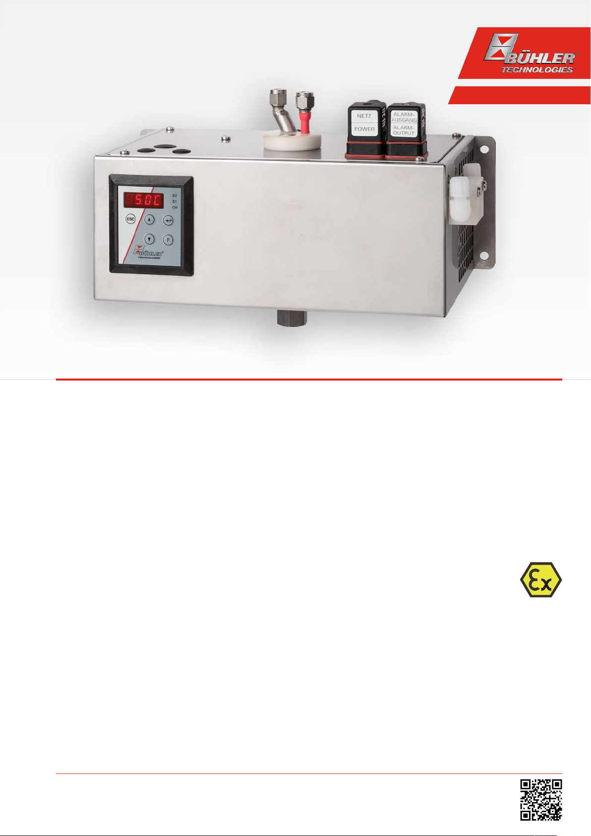
Sample gas cooler
TC-Standard (+) X2
Installation and Operation Instructions
Original instructions
BE440023
10/2018
Bühler Technologies GmbH, Harkortstr. 29, D-40880 Ratingen
Tel. +49 (0) 21 02 / 49 89-0, Fax: +49 (0) 21 02 / 49 89-20
E-Mail: analyse@buehler-technologies.com
Internet: www.buehler-technologies.com
Page 2

Bühler Technologies GmbH, Harkortstr. 29, D-40880 Ratingen
Tel. +49 (0) 21 02 / 49 89-0, Fax: +49 (0) 21 02 / 49 89-20
Internet: www.buehler-technologies.com
E-Mail: analyse@buehler-technologies.com
Read this instruction carefully prior to installation and/or use. Pay attention particularly to all advises and safety instructions to prevent injuries. Bühler Technologies can not be held responsible for misusing
the product or unreliable function due to unauthorised modifications.
All rights reserved. Bühler Technologies GmbH 2019
Document information
Document No..........................................................BE440023
Version..........................................................................10/2018
Page 3

TC-Standard (+) X2
Contents
1 Introduction..................................................................................................................................................................................................................... 3
1.1 Intended use .........................................................................................................................................................................................................3
1.2 Overview ................................................................................................................................................................................................................3
1.3 Type plate ..............................................................................................................................................................................................................4
1.4 Scope of delivery.................................................................................................................................................................................................. 4
1.5 Ordering instructions ........................................................................................................................................................................................ 5
1.5.1 Gas cooler models with one heat exchanger ...............................................................................................................................5
1.5.2 Gas cooler models with two heat exchangers ............................................................................................................................ 6
1.5.3 Gas cooler model with two heat exchangers in series ..............................................................................................................7
2 Safety instructions.........................................................................................................................................................................................................8
2.1 Important notices................................................................................................................................................................................................8
2.2 General hazard warnings .................................................................................................................................................................................9
3 Transport and storage .................................................................................................................................................................................................11
4 Installation and connection.......................................................................................................................................................................................12
4.1 Installation site requirements....................................................................................................................................................................... 12
4.2 Installation .......................................................................................................................................................................................................... 12
4.2.1 Connecting the filter gas connections (optional) ..................................................................................................................... 12
4.2.2 Flow adapter connection (optional).............................................................................................................................................. 12
4.2.3 Connecting the moisture detector (option)................................................................................................................................12
4.2.4 Peristaltic pump connector (optional) ......................................................................................................................................... 13
4.2.5 Connecting the heat exchanger .....................................................................................................................................................13
4.3 Electrical connections ...................................................................................................................................................................................... 14
4.4 Signal outputs.....................................................................................................................................................................................................15
5 Operation and control .................................................................................................................................................................................................17
5.1 Description of functions...................................................................................................................................................................................17
5.2 Delta T control option .......................................................................................................................................................................................17
5.3 Use of menu functions .................................................................................................................................................................................... 18
5.3.1 Lock Menu.............................................................................................................................................................................................18
5.3.2 Menu navigation overview..............................................................................................................................................................19
5.4 Description of menu functions ..................................................................................................................................................................... 21
5.4.1 Main menu ...........................................................................................................................................................................................21
5.4.2 Submenu 1 ............................................................................................................................................................................................ 21
5.4.3 Submenu 1 (global settings)........................................................................................................................................................... 22
5.4.4 Set favourite menu ............................................................................................................................................................................25
6 Maintenance..................................................................................................................................................................................................................26
7 Service and repair......................................................................................................................................................................................................... 27
7.1 Troubleshooting ................................................................................................................................................................................................ 27
7.1.1 Error messages on the display....................................................................................................................................................... 28
7.2 Safety instructions ............................................................................................................................................................................................29
7.3 Cleaning and removal of the heat exchanger...........................................................................................................................................30
7.4 Replacing the hoses of the peristaltic pump (option) ............................................................................................................................30
7.5 Replacing the filter element (option)..........................................................................................................................................................30
7.6 Drying of the moisture detector (option)....................................................................................................................................................31
7.7 Calibration of the moisture detector (option)...........................................................................................................................................31
7.8 Spare parts and accessories ............................................................................................................................................................................31
7.8.1 Consumables and accessories ........................................................................................................................................................32
8 Disposal........................................................................................................................................................................................................................... 33
9 Appendices.....................................................................................................................................................................................................................34
9.1 Gas cooler technical data ................................................................................................................................................................................34
9.2 Technical Data - Options .................................................................................................................................................................................35
9.3 Flow diagrams....................................................................................................................................................................................................36
9.4 Performance curves.......................................................................................................................................................................................... 37
9.5 Heat exchanger ..................................................................................................................................................................................................38
iBühler Technologies GmbHBE440023 ◦ 10/2018
Page 4

TC-Standard (+) X2
9.5.1 Heat exchanger description ........................................................................................................................................................... 38
9.5.2 Heat exchanger overview................................................................................................................................................................ 39
9.6 Dimensions (mm)............................................................................................................................................................................................. 40
10 Attached documents................................................................................................................................................................................................... 41
ii Bühler Technologies GmbH BE440023 ◦ 10/2018
Page 5

TC-Standard (+) X2
1 Introduction
1.1 Intended use
This unit is intended for industrial use in gas analysis systems. It's an essential component for conditioning the sample gas to
protect the analysis instrument from residual moisture in the sample gas.
This device may be operated in a zone 2, explosion class IIC (ATEX & IECEx), explosive gas atmosphere which is rarely and only
temporarily explosive and in Class I, Division 2 (US & Canada).
Optional mounting of various add-on units may limit the area of application of this device.
Cooler with certificate Canada and IECEx
The equipment shall be mounted within a tool-secured IP54 enclosure.
Cooler with certificate USA
The equipment shall be mounted within a tool-secured IP54 enclosure which is capable of accepting one or more of the
ClassIDivision2 wiring methods per the National Electric Code (ANSI/NFPA70).
Cooler with certificate ATEX
The equipment shall be mounted within a IP54 enclosure in accordance with EN60079-15, and in a tool-secured enclosure which
meets the requirements of EN60079-0 and EN60079-15.
Please note the specifications in the data sheet on the specific intended use, existing material combinations, as well as pressure
and temperature limits.
1.2 Overview
The TC-StandardX2 series was designed specifically for high cooling capacities and high ambient temperatures.
The TC-Standard+X2 series was designed specifically for the requirements in so-called automated measuring systems(AMS) according to EN15267-3. The series connection of the heat exchangers will cool in two cycles to minimise wash out effects.
The Peltier cooler is distinguished by two types according to cooling capacity or operation temperature. This classification is reflected in the type designation. The exact item number of the model defined by you is determined by the model code in the category ordering information.
Application Standard applications
Operation temperature 40 °C 50 °C
1 heat exchanger TC-Standard 6111 X2 TC-Standard 6112 X2 3rd digit=1
2 heat exchangers TC-Standard 6121 X2 TC-Standard 6122 X2 3rd digit=2
2 heat exchangers in series TC-Standard+ 6121 X2 TC-Standard+ 6122 X2 3rd digit=2
4th digit=1 4th digit=2
Additional components which every conditioning system should feature can optionally be integrated:
– Peristaltic pump for condensate separation,
– Filter,
– Moisture detector.
This allows for various configurations of cooler and options. Here the approach is to simplify creating a complete system in a
cost-efficient way through pre-installed components with hoses connected. We further paid attention to easy access to wear
parts and consumables.
3Bühler Technologies GmbHBE440023 ◦ 10/2018
Page 6
TC-Standard (+) X2
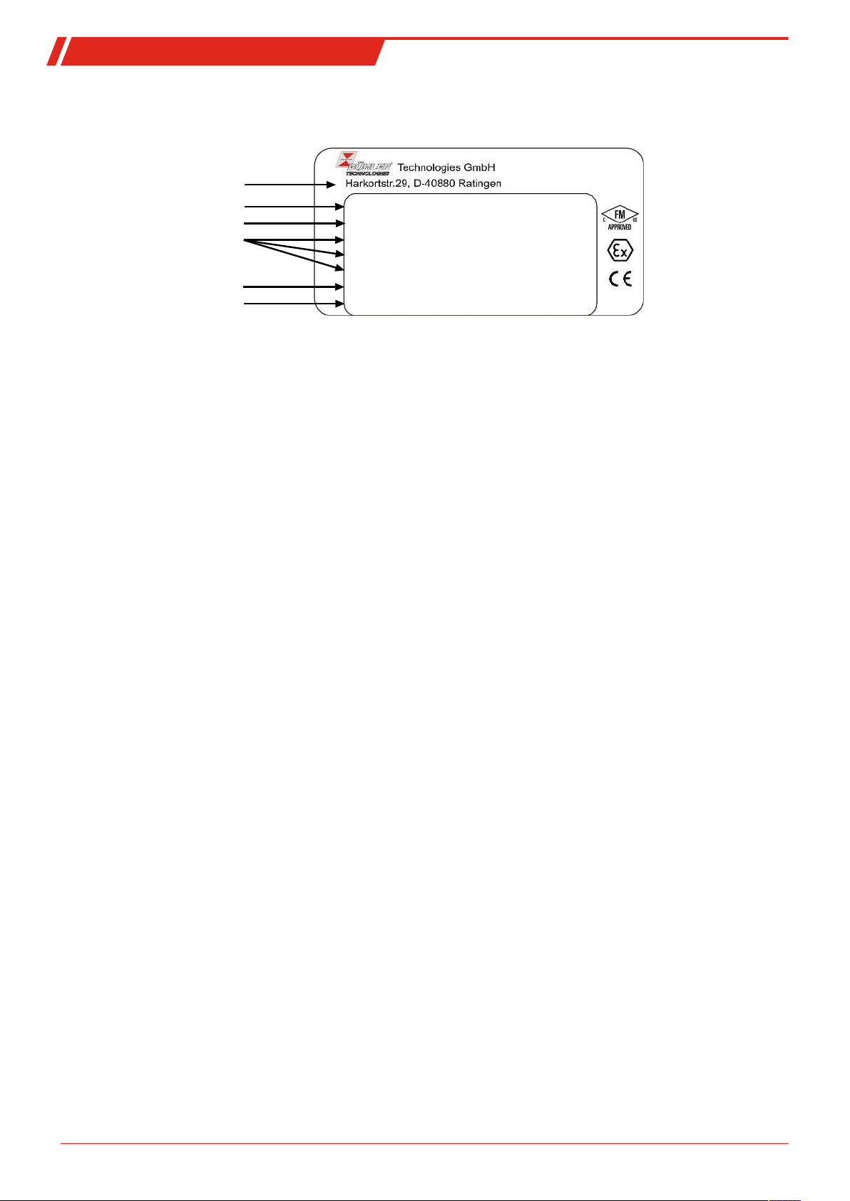
Manufacturer and address
Type designation and voltage
Serial no., Item no.
Blast protection markings
(Atex, IECex and US/Canada)
Description
Year of manufacture
TC-Standard 230 V, 50/60Hz, 130W
101001081115 449621112412510011010
FM18ATEX0012X II 3 G Ex ec nC IIC T4 Gc
IECEx FMG 18.0005X Ex ec nC IIC T4 Gc
USA/Canada: CL I DIV 2 GP ABCD
Tamb: 0°C to 50°C
Year: 2018 Manual doc.no.: BX440023
1.3 Type plate
Example:
1.4 Scope of delivery
– Cooler
– Product documentation
– Connection-/mounting accessories (optional)
4 Bühler Technologies GmbH BE440023 ◦ 10/2018
Page 7

TC-Standard (+) X2
1.5 Ordering instructions
1.5.1 Gas cooler models with one heat exchanger
The item number is a code for the configuration of your unit. Please use the following model code:
4496 2 1 1 X 2 X 1 X X X 0 X X X 0 X 0 Product characteristic
Gas cooler models (with 1 heat exchanger)
1 TC-Standard 6111 X2: Ambient temperature 40 °C
2 TC-Standard 6112 X2: Ambient temperature 50 °C
Certifications
2 for explosive areas
Supply voltage
1 115 VAC, 50/60 Hz
2 230 V AC, 50/60 Hz
4 24 VDC
Heat exchanger
1 1 0 Stainless steel, PTS, metric
1 1 5 Stainless steel, PTS-I, US fitting
1 2 0 Duran glass, PTG, metric
1 2 5 Duran glass, PTG, US fitting
1 3 0 PVDF, PTV, metric
1 3 5 PVDF, PTV-I, US fitting
Peristaltic Pumps *
0 0 without peristaltic pump
1 0 CPsingle X2 with hose nipple, angled
3 0 CPsingle X2 with screw connection
Moisture detector / filter
0 0 without filter, without moisture detector
0 1 without filter, 1 moisture detector with adapter
1 0 1 filter, without moisture detector
1 1 1 filter with built-in moisture detector
Status Outputs
0 0 status output only
1 0 Analog output option, add-on
Delta T-control
0 0 without Delta T-control
1 0 Delta T-control option
* 24 V DC version not available
5Bühler Technologies GmbHBE440023 ◦ 10/2018
Page 8

TC-Standard (+) X2
1.5.2 Gas cooler models with two heat exchangers
The item number is a code for the configuration of your unit. Please use the following model code:
4496 2 1 2 X 2 X 2 X X X 0 X X X 0 X 0 Product characteristic
Gas cooler models (with 2 heat exchangers)
1 TC-Standard 6121 X2: Ambient temperature 40 °C
2 TC-Standard 6122 X2: Ambient temperature 50 °C
Certifications
2 for explosive areas
Supply voltage
1 115 VAC, 50/60 Hz
2 230 V AC, 50/60 Hz
4 24 VDC
Heat exchanger
2 1 0 Stainless steel, 2 MTS, metric
2 1 5 Stainless steel, 2 MTS-I, US fitting
2 2 0 Duran glass, 2 MTG, metric
2 2 5 Duran glass, 2 MTG, US fitting
2 3 0 PVDF, 2 MTV, metric
2 3 5 PVDF, 2 MTV-I, US fitting
Peristaltic Pumps *
0 0 without peristaltic pump
2 0 CPdouble X2 with hose nipple, angled
4 0 CPdouble X2 with screw connection
Moisture detector / filter
0 0 without filter, without moisture detector
0 1 without filter, 1 moisture detector with adapter
0 2 without filter, 2 moisture detectors with adapter
1 0 1 filter, without moisture detector
1 1 1 filter with built-in moisture detector
2 0 2 filters, without moisture detector
2 1 2 filters, 1 moisture detector
2 2 2 filters, 2 moisture detectors
Status Outputs
0 0 status output only
1 0 Analog output option, add-on
Delta T-control
0 0 without Delta T-control
1 0 Delta T-control option
* 24 V DC version not available
6 Bühler Technologies GmbH BE440023 ◦ 10/2018
Page 9

TC-Standard (+) X2
1.5.3 Gas cooler model with two heat exchangers in series
The item number is a code for the configuration of your unit. Please use the following model key:
4496 2 1 2 X 2 X 2 X X X 0 X X X 0 X 0 Product characteristic
Gas cooler models (with 2 heat exchangers in series)
1 TC-Standard+ 6121 X2: Ambient temperature 40 °C
2 TC-Standard+ 6122 X2: Ambient temperature 50 °C
Certifications
2 for explosive areas
Supply voltage
1 115 V AC, 50/60 Hz
2 230 V AC, 50/60 Hz
4 24 V DC
Heat exchanger
2 2 2 Duran glass, 2x MTG-2, metric
2 2 7 Duran glass, 2x MTG-2, US fitting
2 3 2 PVDF, 2x MTV-2, metric
2 3 7 PVDF, 2x MTV-2-I, US fitting
Peristaltic Pumps
0 0 without peristaltic pump
2 0 CPdouble X2 with hose nipple, angled
4 0 CPdouble X2 with screw connection
Moisture detector / filter
0 0 without filter, without moisture detector
0 1 without filter, 1 moisture detector with adapter
1 0 1 filter, without moisture detector
1 1 1 filter with built-in moisture detector
Status outputs
0 0 status output only
1 0 Analog output option, add-on
*
* 24 V DC version not available
7Bühler Technologies GmbHBE440023 ◦ 10/2018
Page 10

TC-Standard (+) X2
DANGER
WARNING
CAUTION
NOTICE
2 Safety instructions
2.1 Important notices
NOTICE
The device is suitable for hazardous areas.
This unit may only be used if:
– The product is being used under the conditions described in the operating- and installation instructions, used according to
the nameplate and for applications for which it is intended. Any unauthorized modifications to the unit will void the warranty provided by Bühler Technologies GmbH,
– The specifications and markings in the type plate must be observed,
– The threshold values in the data sheet and the instructions must be observed,
– Monitoring equipment / protection devices must be connected correctly,
– Service and repair work not described in these instructions are performed by Bühler Technologies GmbH,
– Genuine replacement parts must be used.
Erecting electrical systems in explosive areas requires compliance with the following national regulations:
– IEC/EN60079-14
– National electric code (NEC)
– Canadian electric code (CEC)
Additional national regulations pertaining to initial operation, operation, maintenance, repairs and disposal must be observed.
These operating instructions are a part of the equipment. The manufacturer reserves the right to change performance-, specification- or technical data without prior notice. Please keep these instructions for future reference.
Signal words for warnings
Signal word for an imminent danger with high risk, resulting in severe injuries or death if not avoided.
Signal word for a hazardous situation with medium risk, possibly resulting in severe injuries or death if not
avoided.
Signal word for a hazardous situation with low risk, resulting in damaged to the device or the property or
minor or medium injuries if not avoided.
Signal word for important information to the product.
8 Bühler Technologies GmbH BE440023 ◦ 10/2018
Page 11
TC-Standard (+) X2
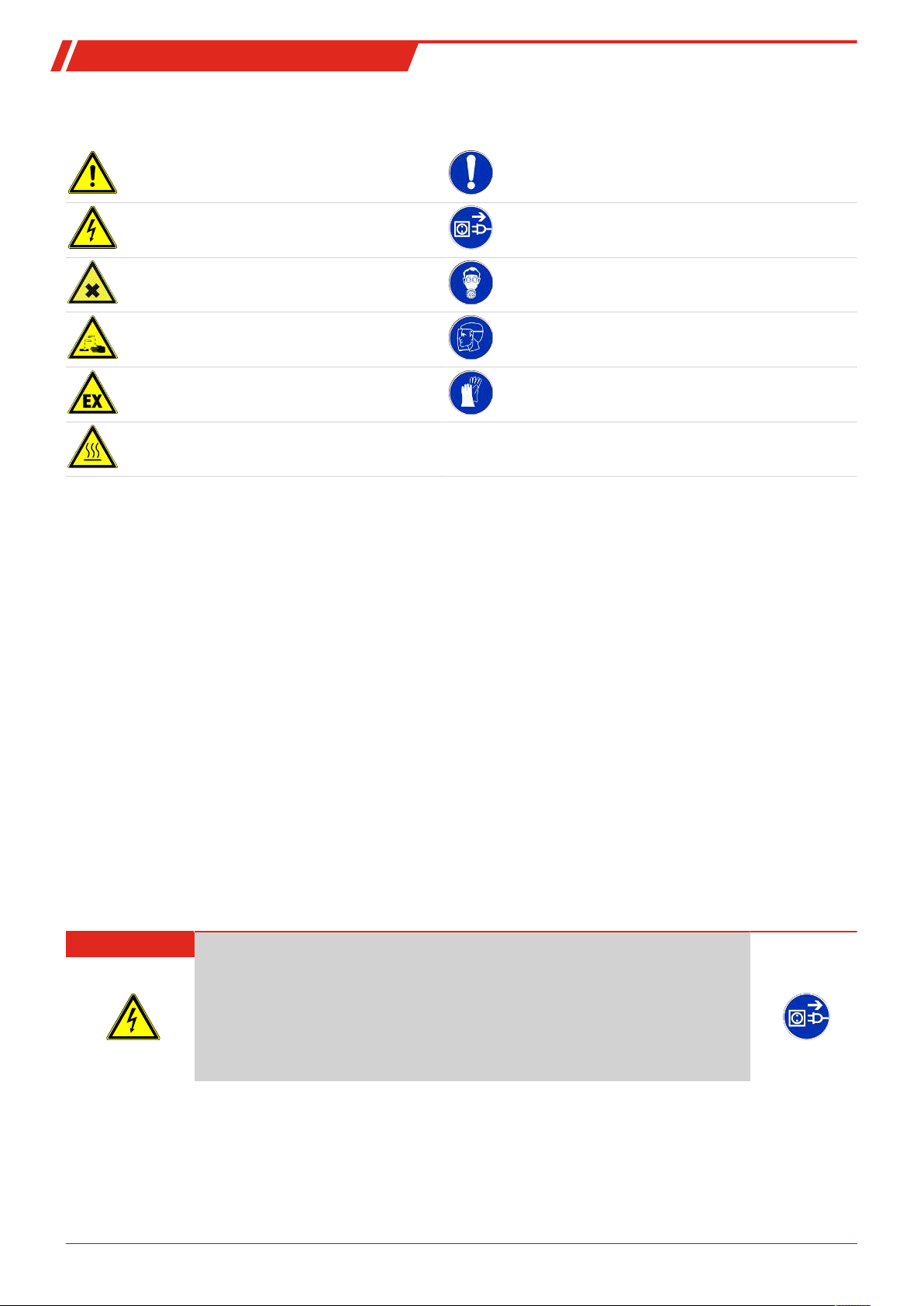
Warning signs
These instructions use the following warning signs:
Warns of a general hazard General notice
Warns of voltage Unplug from mains
Warns not to inhale toxic gasses Wear respiratory equipment
Warns of corrosive liquids Wear a safety mask
Warns of explosive areas Wear gloves
Warns of hot surfaces
2.2 General hazard warnings
The equipment must be installed by a professional familiar with the safety requirements and risks.
Be sure to observe the safety regulations and generally applicable rules of technology relevant for the installation site. Prevent
malfunctions and avoid personal injuries and property damage.
The operator of the system must ensure:
– Safety notices and operating instructions are available and observed,
– The respective national accident prevention regulations are observed,
– The permissible data and operational conditions are maintained,
– Safety guards are used and mandatory maintenance is performed,
– Legal regulations are observed during disposal.
Maintenance, Repair
Please note during maintenance and repairs:
– Repairs to the unit must be performed by Bühler authorised personnel.
– Only perform conversion-, maintenance or installation work described in these operating and installation instructions.
– Always use genuine spare parts.
Always observe the applicable safety and operating regulations in the respective country of use when performing any type of
maintenance.
DANGER Electrical voltage
Electrocution hazard.
a) Disconnect the device from power supply.
b) Make sure that the equipment cannot be reconnected to mains unintentionally.
c) The device must be opened by trained staff only.
d) Regard correct mains voltage.
9Bühler Technologies GmbHBE440023 ◦ 10/2018
Page 12
TC-Standard (+) X2
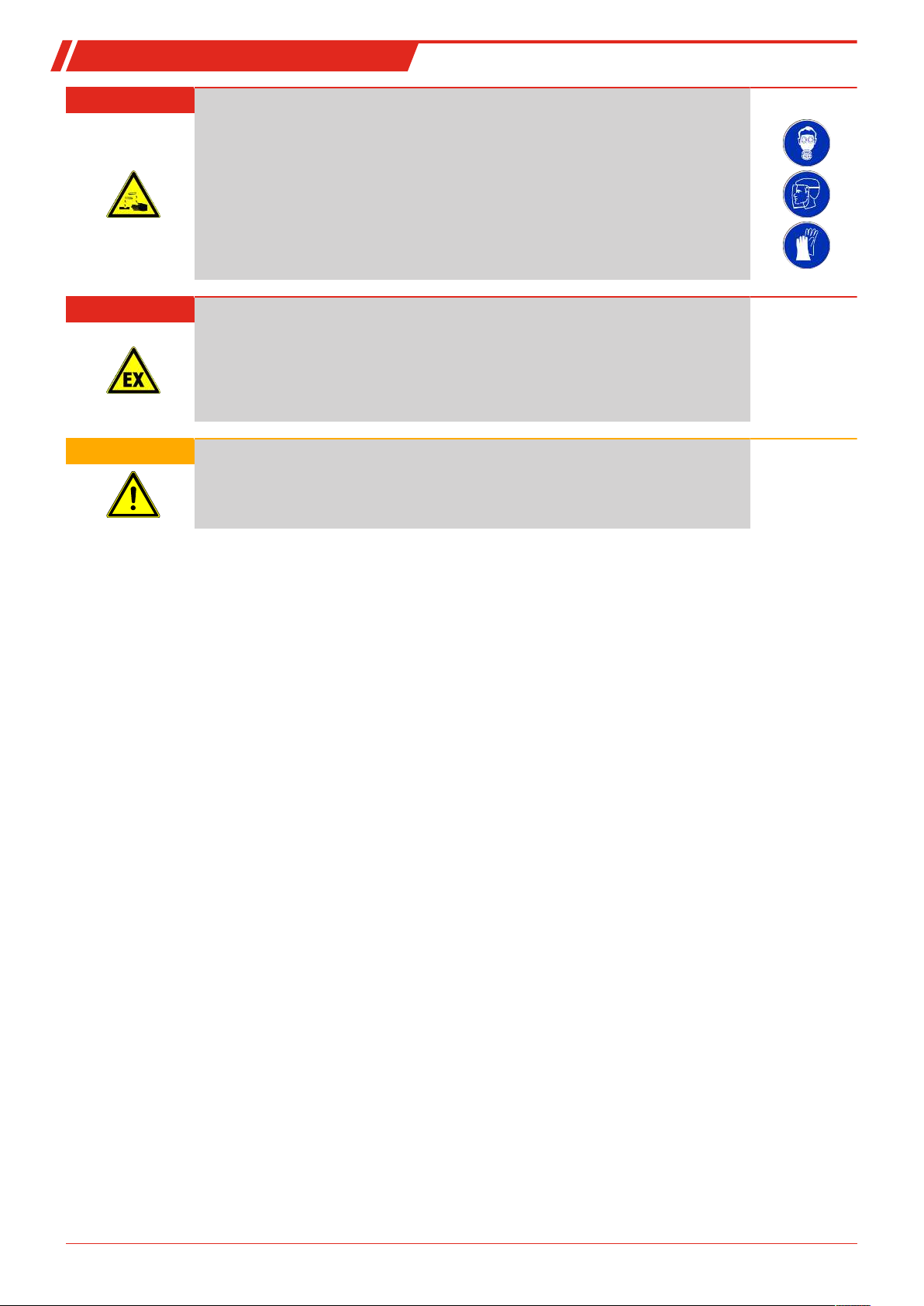
DANGER Toxic, corrosive gas/condensate
Sample gas/condensate may be hazardous to health.
a) If necessary, ensure a safe gas/condensate discharge.
b) Always disconnect the gas supply when performing maintenance or repairs.
c) Protect yourself from toxic/corrosive gasses/condensate when performing mainten-
ance. Wear appropriate protective equipment.
DANGER Explosion hazard
Life and explosion risk may result from gas leakage due to improper use.
a) Use the devices only as described in this manual.
b) Regard the process conditions.
c) Check tubes and hoses for leakage.
WARNING Risk of breakage
a) Protect the equipment against being hit.
b) Protect the device against falling objects.
10 Bühler Technologies GmbH BE440023 ◦ 10/2018
Page 13

TC-Standard (+) X2
3 Transport and storage
Only transport the product inside the original packaging or a suitable alternative.
The equipment must be protected from moisture and heat when not in use. It must be stored in a covered, dry and dust-free
room at a temperature of -20 °C to 60 °C (-4 °F to 140 °F).
11Bühler Technologies GmbHBE440023 ◦ 10/2018
Page 14

TC-Standard (+) X2
4 Installation and connection
4.1 Installation site requirements
The unit is only intended for wall-mounted use in enclosed areas. Adequate protection from the weather must be provided
when used outdoors.
Install the unit leaving enough room below the cooler to discharge the condensate. Leave room above for the gas supply.
Be sure to maintain the approved ambient temperature. Do not obstruct the convection of the cooler. The vents must have
enough room to the next obstacle. The distance must especially be a minimum of 10 cm on the air outlet side.
Ensure adequate ventilation when installing in enclosed housings, e.g. analyser cabinets. If the convection is inadequate, we recommend aerating the cabinet or installing a fan to lower the inside temperature.
4.2 Installation
Run the gas supply to the cooler with a downward slope. The gas inputs are marked in red and additionally labelled "IN".
If a large amount of condensate accumulates, we recommend using a condensate trap with automatic condensate drain. Our
condensate drains, 11LDV38, AK20, AK5.5 OR AK5.2, are suitable.
Glass vessels and automatic condensate drains are available for draining condensate for external mounting below the unit.
When using automatic condensate drains, the sample gas pump must be installed upstream of the cooler (pressure operation)
to ensure proper function of the condensate drain.
If the sample gas pump is located at the cooler outlet (suction operation), we recommend using glass condensate traps or peristaltic pumps.
Connecting the condensate drain
Depending on the material, build a connecting line with fittings and tubing or hose between the heat exchanger and condensate drain. For stainless steel the condensate drain can be hung directly from the connecting tube, for hoses the condensate drain
must be secured separately using a clamp.
The condensate drain can be mounted directly to the heat exchanger.
Condensate lines must always be installed with a slope and a minimum inside diameter of 6 mm (1/4").
The MTG heat exchanger (in coolers with 2 heat exchangers) can only be operated with peristaltic pumps.
4.2.1 Connecting the filter gas connections (optional)
The connection between the heat exchanger outlet and the filter inlet already has tubing. The connection G1/4 or NPT 1/4" (filter
head marked NPT) for the gas outlet must be carefully and properly connected using a suitable screw connection.
When ordering the cooler with the
The filter head is intended for a G1/4 internal screw thread which is plugged at the factory. To use it, unscrew the plug and screw
in a suitable screw connection. Pay attention to leaks.
NOTICE
Installing
Operating pressure ≤ 2 bar
option filter without Moisture detector
filters
limits the maximum approved
, a bypass may be connected to the filter head.
operating pressure
in the system!
4.2.2 Flow adapter connection (optional)
When ordering the cooler with the
The connection between the heat exchanger outlet and the flow adapter inlet does not have tubing included. The connection
G1/4 or NPT1/4" (flow adapter marked NPT) for the gas inlet/outlet must be carefully and properly connected using a suitable
screw connection. Here the direction of flow is not relevant.
option moisture detector without filter
, it will be factory installed inside a flow adapter.
4.2.3 Connecting the moisture detector (option)
When ordering the cooler with
installed and connected in the filter head.
12 Bühler Technologies GmbH BE440023 ◦ 10/2018
moisture detector option
, it will be factory installed inside a flow adapter, or for the
filter option
Page 15
TC-Standard (+) X2
gas out
gas in
gas out
gas in
condensate out
condensate out
Heat exchanger 1
Heat exchanger 2
Gas cooler
(two single heat exchangers)
gas out
gas in
gas out
gas in
condensate out
condensate out
Heat exchanger 1
Heat exchanger 2
Gas cooler +
(two heat exchangers in series)
4.2.4 Peristaltic pump connector (optional)
Coolers ordered with attached peristaltic pump already have it installed and wired. Heat exchangers ordered at the same time
are already installed and connected to the peristaltic pump.
The ø6mm (0.24inch) hose nipple for the pump’s condensate outlet must be carefully and properly connected with a suitable
hose and hose clamp.
Versions with screw connections DN4/6 or 1/6”-1/4” are supplied with ferrule and knurled nut and must be carefully sealed
with appropriate hose.
NOTICE
Installing peristaltic
ating pressure
Operating pressure ≤ 1 bar
pumps
in the system!
CPsingle / CPdouble limits the maximum permissible
oper-
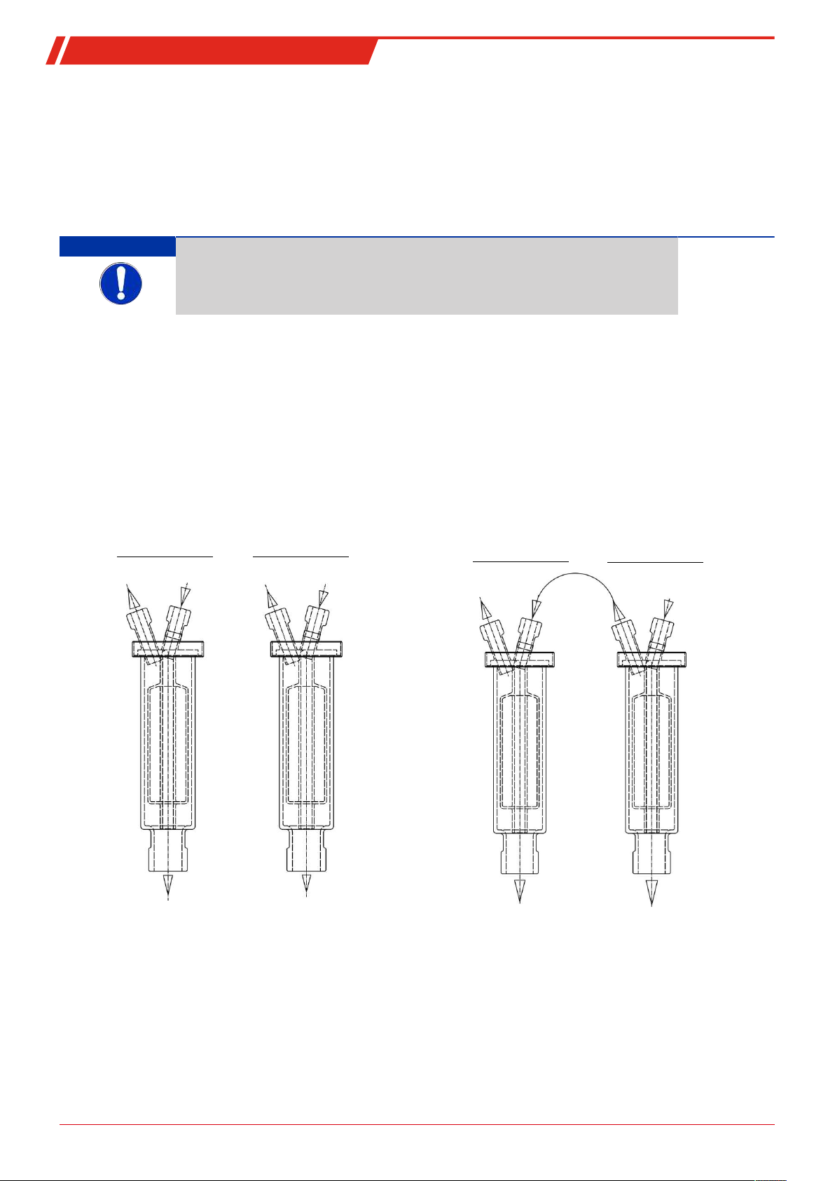
4.2.5 Connecting the heat exchanger
The picture on the left shows the schematics for connecting two separate heat exchangers.
To minimise gas wash out in the cooler, the two (identical) heat exchangers must be operated in series (right picture). This
should be done as follows:
1. Gas inlet line to red gas inlet on heat exchanger 2 (pre-cooling).
2. Connection between gas outlet on heat exchanger 2 and the red gas inlet on heat exchanger 1 (after-cooling).
3. Attaching the final gas output line to the gas outlet on heat exchanger 1.
The gas inputs are marked in red.
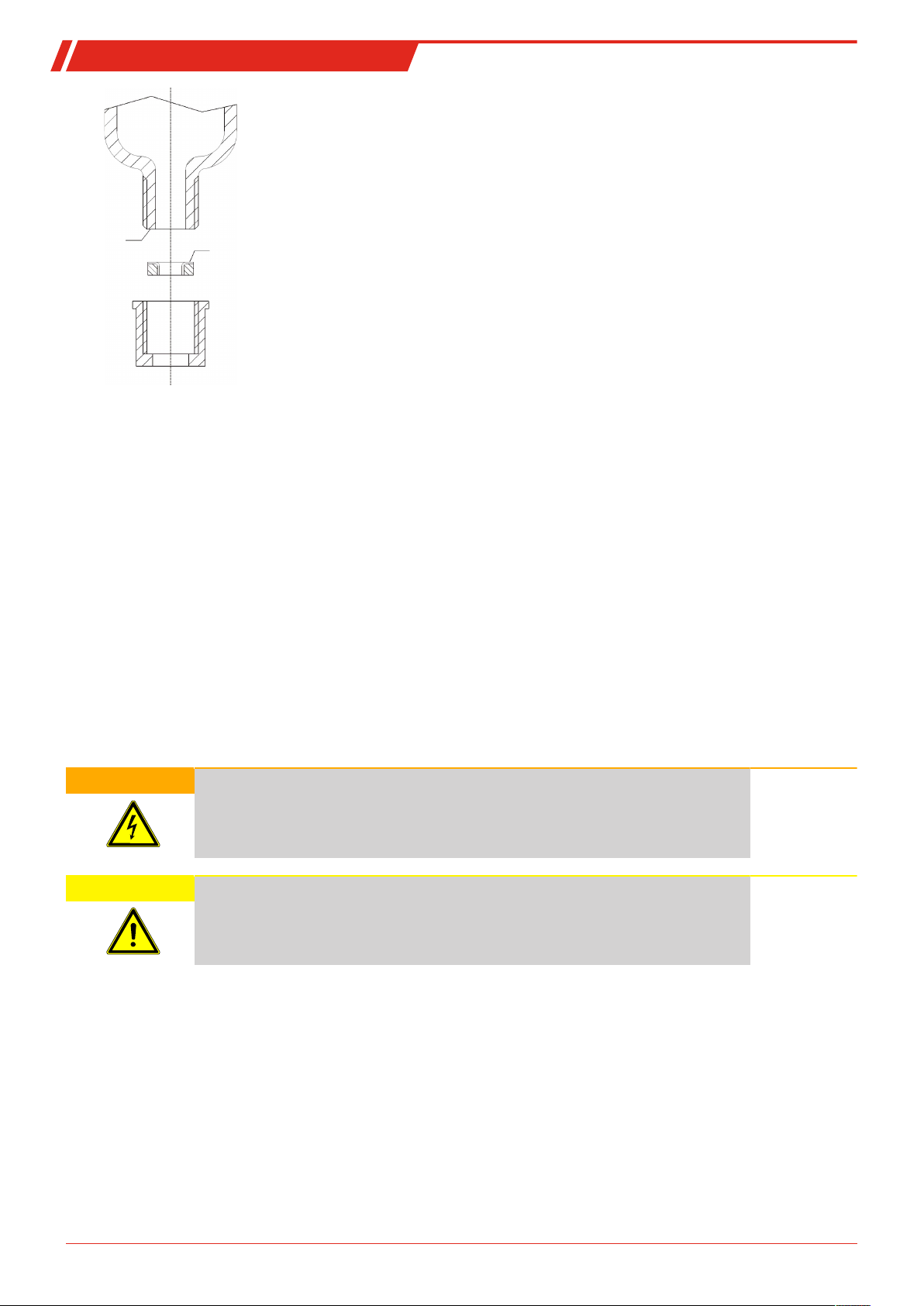
On glass heat exchangers the correct position of the seal is important when connecting the gas lines (see image). The seal consists of a silicone ring with a PTFE sleeve. The PTFE side must face the glass thread.
13Bühler Technologies GmbHBE440023 ◦ 10/2018
Page 16
TC-Standard (+) X2
Glass
PTFE
4.3 Electrical connections
The operator must install an external separator for the device which is clearly assigned to this device.
This separator
– must be located near the device,
– must be easy for the operator to reach,
– must comply with IEC 60947-1 and IEC 60947-3,
– must separate all live conductors and the status output, and
– must not be attached to the power feed.
The mains supply of the device must be fused according to the specifications under technical data.
Potential equalization/static charge
Static charges can result in incendive sparking. Avoid static charges. Any conductive parts of the cooler must be grounded!
The housing has a connection for an earth/equipotential bonding conductor. Ensure the housing is adequately earthed (minimum conductor cross-section 4 mm2).
Particularly observe the requirements of EN 60079-14!
WARNING Hazardous electrical voltage
The device must be installed by trained staff only.
CAUTION Wrong mains voltage
Wrong mains voltage may damage the device.
Regard the correct mains voltage as given on the type plate.
14 Bühler Technologies GmbH BE440023 ◦ 10/2018
Page 17
TC-Standard (+) X2
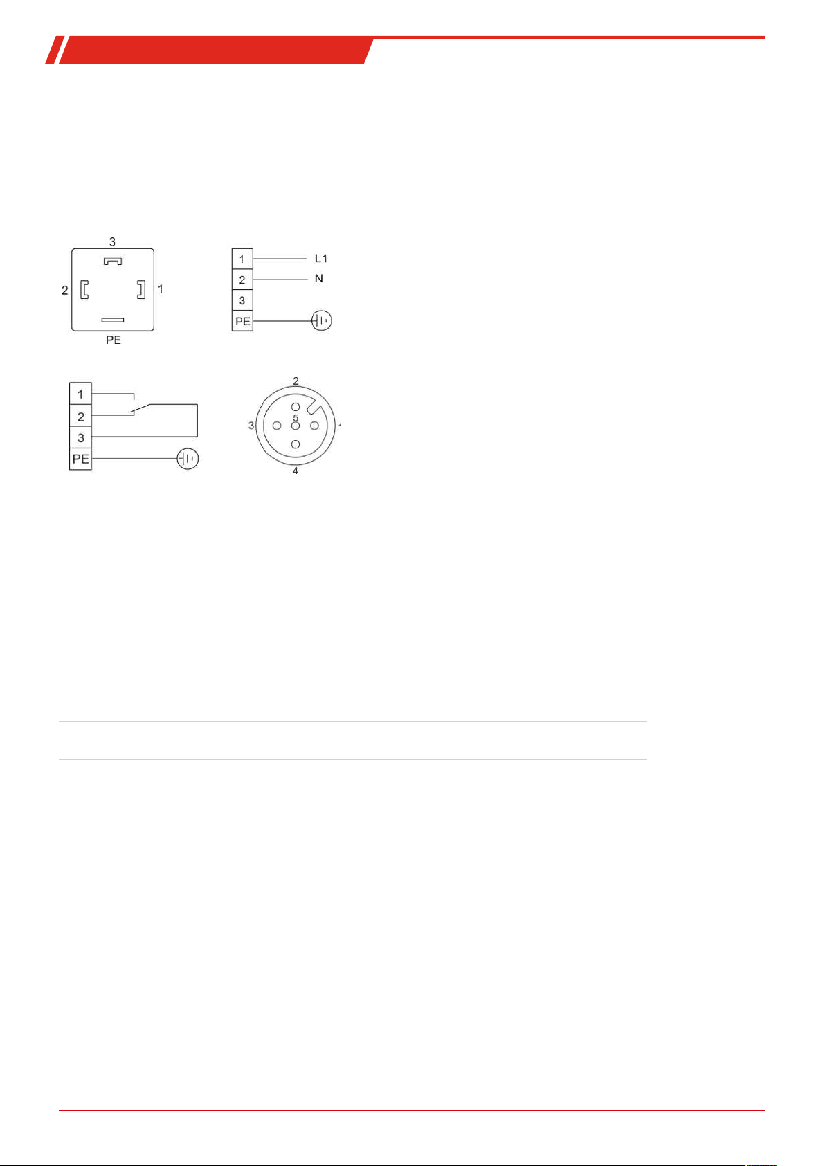
Plug numbering
Electric supply S1
115/230 V (24 V DC)
Alarm contact S2 *
Analogue output S3
1 - N/C
2 - N/C
3 - GND
4 - 4-20 mA out
5 - shield
(+24 V)
(-24 V)
*
Connection via plug
The device is equipped with connectors according to EN 175301-803 for mains and status output. If the cables are mounted properly, they cannot be interchanged. Please make sure that the connectors are remounted correctly after connecting the cable. The
following figures show the pin assignment with respect to the numbers printed on the connector.
The supply line cross-sections must be suitable for the rated current. Use a maximum line cross-section of 1.5mm² (AWG16) and
a cable diameter of 8-10mm (0.31-0.39 inch).
* When using an alarm contact connect to ≥33VAC or ≥70VDC PE voltage.
The clamping area has a diameter of 8-10mm (0.31–0.39 inch).
4.4 Signal outputs
The device provides different status signals. The maximum switching load of the alarm outputs is limited to 250VAC/150VDC,
2A, 50VA each.
An alarm is triggered by the alarm contact/status output (S2) if the temperature of the cooler is outside the specified limits. It
does not indicate if the alarm was triggered due to excess temperature or insufficient temperature.
The front film has three LEDs:
Colour Marking Function
Red S2 High/low temperature, device error
Yellow S1 --Green OP Normal operation
The LEDs OP and S2 indicate the device status similar to S2.
If the option “temperature signal” is built in, the unit has a signal output via the analogue output to indicate the actual cooler
temperature.
When the moisture detector (optional) is installed, an alarm is activated by the alarm contact/status output (S2) if the moisture
is still present in the prepared sample gas. Thereby, no distinction is made between the alarm/cable break triggered by moisture
detector 1 or 2. This information is displayed by an error message instead.
The temperature signal can be read via the panel plug (S3) using the M12x1 connector. This plug is located next to the moisture
detector connectors at the top of the cooler.
15Bühler Technologies GmbHBE440023 ◦ 10/2018
Page 18

TC-Standard (+) X2
Description of signal outputs
Function / contact
type
Regarding S2) internal changeover
contact: max.
250VAC / 150VDC,
2A, 50VA
Regarding S3) 4-20mA analogue
output
(R
<500Ω)
Load
Description
the following device statuses can
be indicated via two switching
outputs:
Signalling of actual temperature
(please use shielded cables)
Contact between 3 and 2 closed (alarm)
– No mains voltage and/or actual temperature out-
side the alarm thresholds
Contact between 3 and 1 closed (ok)
– Mains voltage attached + actual temperature
within the alarm thresholds
With moisture detector option
Contact between 3 and 2 closed (alarm)
– The moisture detector registers residual humidity
in the sample gas or cable break: Error message
Contact between 1 and 3 closed (ok)
– no residual moisture in measuring gas / no cable
break
With temperature signal option
T
= -20°C ≙ (-4°F) -> 4mA/ 2 V
Cooler
T
= 5°C ≙ (41°F) -> 9mA/ 4,5 V
Cooler
T
= 60°C ≙ (140°F) -> 20mA/ 10 V
Cooler
16 Bühler Technologies GmbH BE440023 ◦ 10/2018
Page 19

TC-Standard (+) X2
5 Operation and control
NOTICE
The device must not be operated beyond its specifications.
After switching on the cooler the block temperature will be displayed. The display will flash until the block temperature has
reached the preset target value (± adjustable alarm range). The status contact is in the Alarm position.
Once the target temperature range has been reached, the temperature will continuously be displayed and the status contact
switches over.
If the display flashes during operation or an error message appears, please refer to bullet “Troubleshooting”.
Please refer to the data sheet for performance data and maximum ratings.
5.1 Description of functions
The cooler is controlled by a microprocessor. With the factory preset the control already incorporates the various characteristics
of the built-in heat exchangers.
The programmable display shows the block temperature in the selected display unit (°C/°F) (factory preset °C). Application-specific settings can easily be configured guided by the menu, using the 5 buttons. For one, this applies to the target outlet dew
point, which can be set from 2 to 20°C (36°F to 68°F) (factory preset 5°C/41°F).
And then the warning thresholds can be adjusted for low and excess temperature. These are set relative to the outlet dew point
τa setting.
For the low temperature the range is τa -1 to - 3K (at a minimum 1°C/ 34°F cooling block temperature), for the excess temperature the range is τa +1 to +7K. The factory presets for both values are 3K.
The flashing display and the status relays indicate the conditions are below or above the configured warning range (e.g. after
switching on).
The status output can e.g. be used to control the sample gas pump to allow for the gas flow to only be switched on once the permissible cooling range has been reached or shut off the pump in the event of a moisture detector alarm.
The separated condensate can be drained via connected peristaltic pumps or add-on automatic condensate drains.
Fine mesh filters can also be used, which in turn can be installed in optional moisture detectors.
The glass dome allows the dirt level of the filter element to easily be determined.
The moisture detector is easy to remove. This may be required if a condensate enters the cooler due to a malfunction and the
peristaltic pump or the automatic condensate drain is unable to remove it.
5.2 Delta T control option
Not all applications require an outlet dew point of 5°C (41°F). In some applications a higher dew point is sufficient. In other applications a stable outlet dew point doesn’t matter, it’s enough for the gas to be dry, so if the outlet dew point has an adequate
difference in temperature below the ambient temperature.
Here the electronics measure the ambient temperature and regulate the outlet dew point to an adjustable value below it. This
extends the potential cooling capacity to the limits of the heat exchanger. Here it’s important to note the outlet dew point fluctuates along with the ambient temperature and a stable dew point cannot be a prerequisite for the measurement.
The target temperature range is defined by the ambient temperature, the adjustable temperature difference and the alarm limits. If the block temperature is not within the target range with active Delta T-control, the status message "dt" will flash in the
display.
Example:
to an ambient temperature of approx. 35°C (95°F), and the safe drop is only preferred over the ambient temperature with ambient temperature peaks over 35°C (95°F). The cooling capacity specified in the cooling capacity graphs at 35°C (95°F) is then
available at above 35°C (95°F).
At a difference of 30°C (30 K/54 °F), at a set outlet dew point of 5°C (41°F) this means the dew point remains stable up
17Bühler Technologies GmbHBE440023 ◦ 10/2018
Page 20

TC-Standard (+) X2
OK
ESC
F
Func
5.3 Use of menu functions
Brief description of the operating principle:
The unit is operated using 5 keys. Their functions are:
Button Section Functions
Display – Switches from the measurement display to the main menu
or
or
Menu – Selects the menu item displayed
Enter – Applies an edited value or a selection
Display – temporarily switches to the alternative measurement display (if option installed)
Menu – Back
Enter – Increase value or browse selection
– Note:
– Press button 1 x = changes parameter / value by one;
– Hold button = fast mode (numerical values only)
– Display flashes: modified parameter/value
– Steady display: original display/value
Display – temporarily switches to the alternative measurement display (if option installed)
Menu – Next
Enter – Reduce value or browse selection
Menu – Move one level up
Enter – Return to menu
Changes will not be saved!
– Sets a menu to favourite.
(Note: The favourite menu will also be activated with the menu locked!)
5.3.1 Lock Menu
Some menus can be locked to prevent inadvertently changing the settings of the unit. This requires setting a code. For information on setting up or disabling the menu lock please refer to "Global Settings" (toP) under menu item toP>Loc.
The menu lock is
With the menu locked, only the following menu items will be visible without entering the correct code:
Menu item Explanation
toP > unit Temperature unit selection (°C or °F).
F or Func. Accessing the Favourites menu
not
enabled at the time of delivery, all menu items can be accessed.
NOTICE!This menu may be one that is normally locked.
18 Bühler Technologies GmbH BE440023 ◦ 10/2018
Page 21

TC-Standard (+) X2
Top Settings
top
Globale Einstellungen
3
21
Eingabe
5'C
-20 . . . 60 'C
6
54
Auswahl
oP
op haLf Lo hi
9
87
10
5.3.2 Menu navigation overview
When pressing the OK button in normal mode, the display will show the prompt code if the menu is locked. Use the ▲ and ▼
buttons to enter the correct code and press OK.
If an incorrect code or no code is entered, the menu will not be unlocked and you will not be able to access all menu items.
If you forgot the password you can always enter master code 287 to access the menu; the menu will be unlocked.
The following image shows an overview of the menu structure.
Items with a dashed frame will only appear with the respective settings or with the respective status messages.
The factory defaults and settings ranges are specified in the overview as well as under the respective menu item. The factory defaults apply unless otherwise agreed.
You can cancel entries and menu selections without saving by pressing the
ESC
key.
Menu:
Parameter:
Optional menu
navigation:
1.
Menu designation
2.
Display
3.
Brief description
4.
Value input
5.
Factory preset
6.
Parameter range
7.
Selecting from the list of values
8.
Factory preset
9.
Parameter range/selection
10. dashed box = Optional
19Bühler Technologies GmbHBE440023 ◦ 10/2018
Page 22

TC-Standard (+) X2
Login
Loc
Enable menu lock
Selection
noP
nop- haLf - Lo - hi
OK
OK
OK
OK
OK
OK
OK
Input
0
0. . . . 9999
OK
OK
Selection
unit
°C - °F
Reset
rSt
Factory settings
Exit
E
Close submenu
TC Standard
tcSt
Device designation
Display
ch1
Temperature CH1
Display
ch2
Ambient temperature CH2
Top Settings
top
Global settings
Analogue Out1
An1
Settings menu Analog 1
Settings menu
unit
Temperature unit
Temperature
tEmP
Target temp. Cooling block
Exit
E
Close submenu
Drop-down menu
cout
Functional test
Exit
E
Close submenu
OK
Display Main menu Submenu 1 Submenu 2 Parameter
Input
5°C
2 . . . 20 °C
OK
OK
Input
3°C
1 . . . 7 °C
Settings menu
A hi
Alarm hysteresis
Settings menu
A Lo
Alarm hysteresis
Drop-down menu
dt
DeltaT Temp. Mode
OK
OK
Drop-down menu
h2o
Drop-down menu
sen
Moisture detector 1 sensitivity
Drop-down menu
h2o.2
Drop-down menu
sen.2
OK
Input
-3°C
-1 . . . -3 °C
OK
Calibrate moisture detector 1
Calibrate moisture detector 2
Moisture detector 2 sensitivity
Drop-down menu
Modes
Deactivate DeltaT mode
OK
Selection
Abso
Abso - dt
Drop-down menu
out
Output signal
Selection
i
i- u
rst
OK
Input
non
non - hi - Lo
OK
rst
OK
Input
non
non - hi - Lo
OK
Confirm
rst
yes - no
OK
Exit
E
Close submenu
Drop-down menu
PuMP
Stop pumps
Input
-15°C
-30°C .. . .0°C K
Drop-down menu
noP
NoP - off
OK
Moisture detector 1
Moisture detector 2
Confirm
Confirm
Error
Err
Status message
Drop-down menu
hLtc
Humidity auto reset
Input
no
yes - no
OK
Drop-down menu
bLtc
Cable break auto reset
Input
YES
yes - no
OK
Restart
rESt
Restart device
Confirm
no
yes - no
OK
Drop-down menu
h.chn
Heat exchanger material selection
Drop-down menu
tS
tS
OK
t6
tU
(Steel)
(Glass)
(PVDF)
Fig.1: Menu Overview TC Standard
20 Bühler Technologies GmbH BE440023 ◦ 10/2018
Page 23

TC-Standard (+) X2
5.4 Description of menu functions
5.4.1 Main menu
Peltier Cooler TC-Standard (tc.St)
Display → tc.st
This will take you to the cooler target temperature and the tolerance range setting (alarm
threshold).
Global setting (ToP Settings)
Display → toP
This menu is used to configure the global cooler settings.
Peristaltic Pump
Display → PuMP
Switching the peristaltic pump on and off.
Parameter range: NoP , oFF
Factory setting: NoP
Note: Status switches, "PuMP" flashes.
Heat exchanger material selection
Display → h.chn
Heat exchanger material selection
Parameter range: tS (Steel), t6 (Glass), tU (PVDF)
Factory setting: tS (cooler without heat exchanger), or respective material per configuration
Exit main menu
Display → E
Selecting this will return you to display mode.
5.4.2 Submenu 1
Target temperature (Temperature)
Display → Cooler → temp
This setting determines the nominal temperature for the cooler temperature.
Parameter range: 2 °C to 20 °C (35.6 °F to 68 °F)
Factory setting: 5 °C (41 °F)
Note: If the temperature is changed the indicator may blink, until the new operating range has been
reached.
This menu item is hidden if the keylock is enabled.
21Bühler Technologies GmbHBE440023 ◦ 10/2018
Page 24

TC-Standard (+) X2
upper alarm limit (alarm high)
Display → Cooler → A hi
Here you can set the upper threshold for the visual signal and the alarm relay. The alarm limit is set
based on the cooler temperature setting.
Parameter range: 1 °C to 7 °C (1.8 °F to 12.6 °F)
Factory setting: 3 °C (5.4 °F)
Note: This menu item is hidden if the keylock is enabled.
lower alarm limit (alarm low)
Display → Cooler → A Lo
Here you can set the lower threshold for the visual signal and the alarm relay. The alarm limit is set
based on the cooler temperature setting.
Parameter range: -1 °C to -3 °C (-1.8 °F to -5.4 °F)
Factory setting: -3 °C (-5.4 °F)
Note: This menu item is hidden if the keylock is enabled.
DeltaT (dt)
Display → Cooler → dt
Here you can set the nominal difference with respect to ambient temperature.
Parameter range: -30 K…0 K
Factory setting: -15 K
Note: This menu will be hidden if the menu is locked.
DeltaT mode (Modu)
Display → Cooler → Modu
Here you can activate or deactivate DeltaT-mode.
Parameter range: AbSo , dt
Factory setting: AbSo (normal operation mode)
Note: This menu will be hidden if the menu is locked.
Exit submenu 1
Display → Submenu → E
Selecting this will return you to the main menu.
5.4.3 Submenu 1 (global settings)
Temperature unit
Display → toP → unit
Used to select the temperature display unit.
Parameter range: °C, °F
Factory setting: °C
22 Bühler Technologies GmbH BE440023 ◦ 10/2018
Page 25

TC-Standard (+) X2
Analog output
Display → toP → An1
This submenu is used to specify the settings for analog output 1, see chapter Submenu 2 (Analog
Output 1)
Note: This menu will be hidden if the menu is locked.
Calibrate moisture detector
Display → toP → h2o (h2o)
If a moisture detector is installed, calibration can now be performed. To do so, the unit must be
flushed with dry gas.
Note: Calibration was performed at the factory using ambient air. After replacing the moisture detector a
calibration is again required.
Calibrating the moisture detector will set the menu sEn to hi.
This menu will be hidden if the menu is locked.
If the unit has multiple moisture detectors built in, they will be numbered in the menu. In this case, h2o indicates the first, h2o2
the second moisture detector. The same applies to setting the sensor sensitivity in menu SEn.
Moisture detector sensitivity
Display → toP → SEn
If moisture detectors are installed, the sensitivity can be reduced here.
Parameter range: hi: high sensitivity
Lo: low sensitivity
non: no moisture detector
Factory setting: hi
Note: This menu will be hidden if the menu is locked.
Moisture detector: automatic reset following moisture ingress
Display → toP → hLtc
(hLtc = humidity latch). The setting applies to all connected moisture detectors.
Specifies whether the moisture ingress message must be reset manually or will automatically be re-
set after the sensor dries.
Parameter range: YES: The status will be indicated until the user restarts the device and the pumps will be disabled.
no: The status message will automatically be cleared/the pumps will be released again once mois-
ture is no longer detected.
Factory setting: no
Note: This menu will be hidden if the menu is locked.
23Bühler Technologies GmbHBE440023 ◦ 10/2018
Page 26

TC-Standard (+) X2
Moisture detector: error cleared automatically after cable break
Display → toP → bLtc
(bLtc = broken wire latch). The setting applies to all connected moisture detectors.
Determines whether the cable break alarm must be reset manually or will automatically clear on
valid measuring signal.
Parameter range: YES: The status will be indicated until the user restarts the device/clears the error, and the pumps
will be disabled.
no: The error message will extinguish/the pumps will be released again once the moisture detector
is recognised again.
Factory setting: YES
Note: This menu will be hidden if the menu is locked.
Lock Menu
To protect the menu from unauthorised use, enter a value for the lock code. Menu items can then only be accessed after entering the correct code.
Display → toP → Loc
This setting will cancel/enable the menu lock.
Parameter range: 0 to 9999
Factory setting: 0 (keylock cancelled)
Note: This menu will be hidden if the menu is locked.
Restart
Display → toP → rESt
(rESt = restart)
The device will restart, all settings are saved. All error messages will be reset.
The moisture detector will be reset, irrespective of the settings in menus h.Itc and h.Moi.
Parameter range: YES: Restart. The display will show the software version for the device and returns to measurement
display.
no: Exit menu without restarting.
Note: The user settings will be saved.
Factory settings
Display → toP → rst
This setting restores the factory settings.
Parameter range: Yes: factory settings restored.
No: Exit menu without making changes.
Factory setting: No
Note: This menu will be hidden if the menu is locked.
Exit submenu 1
Display → Submenu → E
Selecting this will return you to the main menu.
24 Bühler Technologies GmbH BE440023 ◦ 10/2018
Page 27

TC-Standard (+) X2
5.4.3.1 Submenu 2 (Analog Output 1)
The analog output will display the actual cooler temperature.
Signal behaviour
In normal mode (noP) the measuring point will output the actual temperature. For testing purposes you can generate constant
values hi, Lo or hALF. The analogue output will output a constant signal with a value as specified in the table.
Constant Current output
4 – 20 mA
hi 20 mA 10 V
Mi 12 mA 6 V
Lo 4 mA 2 V
noP 4 – 20 mA 2 – 10 V
After testing, the signal behaviour must be changed back to normal mode (noP).
Display → toP → An1 → cout
This setting determines how the analogue output will behave.
Parameter range: noP = Operation (normal mode), hi, Lo, hALF
Factory setting: noP
Note: This menu will be hidden if the menu is locked.
Voltage output
2 – 10 V
Selection -> Output Signal
Display → toP → An1 → out
Select the type of output signal.
Parameter range: i Status output 4… 20mA
u Status output 2…10V
Factory setting: i
Note: Disconnect meter before switching!
This menu item is hidden if the keylock is enabled.
Exit Submenu 2
Display → toP → An1 → E
Selecting this will return you to submenu 1.
5.4.4 Set favourite menu
Use the F or
– Open the menu you wish to set as the favourite. This menu can also be a lockable menu.
– Press the function key for more than 3 sec.
The current menu has been set as the favourite. The display will briefly show the message Func.
– Press
To now access the favourite menu, press the F or
NOTICE!The favourite menu can also be accessed if the menu is locked.
Func
(function) key to set a favourite menu to later open it with just the push of a button.
ESC
or E (Exit) to return to the display.
Func
key.
25Bühler Technologies GmbHBE440023 ◦ 10/2018
Page 28

TC-Standard (+) X2
6 Maintenance
If the cooler is delivered in basic configuration, no special maintenance is necessary.
Nevertheless, depending on the configuration different options or accessories may be installed. In this case, follow the maintenance schedule in regular intervals.
Option peristaltic pump:
–
Option filter:
–
Option moisture detector:
–
During maintenance, remember:
– The equipment must be maintained by a professional familiar with the safety requirements and risks.
– Only perform maintenance work described in these operating and installation instructions.
– When performing maintenance of any type, observe the respective safety and operation regulations.
DANGER Electrical voltage
Checking the filter element
Checking the hoses
Calibrating the moisture detector
Electrocution hazard.
a) Disconnect the device from power supply.
b) Make sure that the equipment cannot be reconnected to mains unintentionally.
c) The device must be opened by trained staff only.
d) Regard correct mains voltage.
DANGER Toxic, corrosive gas/condensate
Sample gas/condensate may be hazardous to health.
a) If necessary, ensure a safe gas/condensate discharge.
b) Always disconnect the gas supply when performing maintenance or repairs.
c) Protect yourself from toxic/corrosive gasses/condensate when performing mainten-
ance. Wear appropriate protective equipment.
26 Bühler Technologies GmbH BE440023 ◦ 10/2018
Page 29

TC-Standard (+) X2
7 Service and repair
This chapter contains information on troubleshooting and correction should an error occur during operation.
Repairs to the unit must be performed by Bühler authorised personnel.
Please contact our Service Department with any questions:
Tel.: +49-(0)2102-498955
If the equipment is not functioning properly after correcting any malfunctions and switching on the power, it must be inspected
by the manufacturer. Please send the equipment inside suitable packaging to:
Bühler Technologies GmbH
- Reparatur/Service -
Harkortstraße 29
40880 Ratingen
Germany
Please also attach the completed and signed RMA decontamination statement to the packaging. We will otherwise be unable to
process your repair order.
You will find the form in the appendix of these instructions, or simply request it by e-mail:
service@buehler-technologies.com
or your agent
.
7.1 Troubleshooting
Problem / Malfunction Possible cause Action
Condensate inside the gas
outlet
Reduced gas flow rate – Gas circuit clogged – Uninstall and clean heat exchanger
Excess temperature – Operating point not yet reached – Wait (max. 20 min)
Insufficient temperature – Faulty control – Send in cooler
– Condensate trap full – Empty condensate trap
– Valve inside the automatic condensate
drain may be stuck
– Cooler overloaded – Maintain limits
– Condensate outlet iced over – Send in unit
– Cooling outlet too long despite the cooler
running
– Flow rate / dew point / gas temperature too
high
– Installed fan stopped – Check and replace if necessary
– Flush in both directions
– if necessary, replace filter element
– Be sure the vents are not covered (heat
buildup)
– Maintain limits / install pre-separator
27Bühler Technologies GmbHBE440023 ◦ 10/2018
Page 30

TC-Standard (+) X2
7.1.1 Error messages on the display
If an error occurs, the display will read "Err". Press the " " button to show the error number(s).
Error messages will appear until the unit has been restarted or the error is cleared using the "Func" button. It can only be cleared
if the cause for the error has been corrected.
Causes / Action: The following is a list of the most common causes and actions for the respective error. If the actions listed do
not resolve the problem, please contact Service.
Problem / Malfunction Possible cause Action
No display – No voltage
– Loose connecting cable
– Display defective
D1.02 (The software version for the display will ap-
(permanent)
Error – An error has occurred – Read the error number as described above
Error 01 – Controller malfunction – Clear error (temporary fault)
Error 03 – Microcontroller Fault / MCP2 – Contact service
pear).
– Not communicating with the controller
– Check the supply cable
– Check fuse
– Check connections
– Check connections
– Disconnect from power for approx. 5 s
– Contact service
Error 04 – EEPROM error – Contact service
Error 22 – Moisture detector 1 cable break – Check moisture detector line
– Check moisture detector
Error 32 – Moisture detector 2 cable break – Check moisture detector line
– Check moisture detector
Error 40 – General error temperature sensor 1 – Sensor possibly defective
Error 41 – Low temperature / short-circuit temperat-
ure sensor 1
Error 42 – Excess temperature / short-circuit temper-
ature sensor 1
Error 43 – Measurement fluctuation temperature
sensor 1
Error 50 – General error temperature sensor 2 – Sensor possibly defective
Error 51 – Low temperature / short-circuit temperat-
ure sensor 2
Error 52 – Excess temperature / short-circuit temper-
ature sensor 2
Error 53 – Measurement fluctuation temperature
sensor 2
– Check temperature sensor connection
– Check temperature sensor connection
– Check temperature sensor connection
– Check temperature sensor connection
– Check temperature sensor connection
– Check temperature sensor connection
28 Bühler Technologies GmbH BE440023 ◦ 10/2018
Page 31

TC-Standard (+) X2
Status text Possible cause Action
H2o.1 – Moisture alarm moisture detector 1 – Dry
– Check condensate trap
H2o.2 – Moisture alarm moisture detector 2 – Dry
– Check condensate trap
init – Initialisation phase – Wait
PuMP – Pumps deactivated – Reactive pumps via menu
dt Active Delta T control only: The block temperat-
ure is outside the defined temperature range.
– Cooler is still in the "break-in phase"
– Fluctuating ambient temperature
– Insufficient cooling capacity
– Excess/low temperature – see chapter “Troubleshooting”
(Flashing)
– Wait to see if the target temperature will be
– Check the ambient temperature / power sup-
– Process-related: Adjust alarm limits
7.2 Safety instructions
– The device must be operated within its specifications.
– All repairs must be carried out by Bühler authorised personnel only.
– Only perform modifications, servicing or mounting described in this manual.
– Only use original spare parts.
DANGER Electrical voltage
Electrocution hazard.
a) Disconnect the device from power supply.
b) Make sure that the equipment cannot be reconnected to mains unintentionally.
c) The device must be opened by trained staff only.
d) Regard correct mains voltage.
reached
plied
DANGER Toxic, corrosive gas/condensate
Sample gas/condensate may be hazardous to health.
a) If necessary, ensure a safe gas/condensate discharge.
b) Always disconnect the gas supply when performing maintenance or repairs.
c) Protect yourself from toxic/corrosive gasses/condensate when performing mainten-
ance. Wear appropriate protective equipment.
CAUTION Health hazard if the heat exchanger leaks
The heat exchanger is charged with glycol-based coolant.
In the event of a heat exchanger leak:
a) Avoid contact with the skin and eyes.
b) In the event of a leak, do not restart the cooler under any circumstances The cooler
must be repaired by the manufacturer.
29Bühler Technologies GmbHBE440023 ◦ 10/2018
Page 32

TC-Standard (+) X2
7.3 Cleaning and removal of the heat exchanger
Heat exchangers only need to be replaced or maintained if clogged or damaged. If they are clogged, we recommend checking if
using a filter will avoid future occurrences.
– Close gas supply.
– Switch off device and disconnect all plugs (e.g. connector plug alarm output, supply input, etc.).
– Disconnect gas connections and condensate drain.
– Pull the heat exchanger up and out.
– Clean the heat exchanger hole (hole inside the cooler block), as the heat exchangers are installed with silicone grease.
– Flush the heat exchanger until all contaminants have been removed.
– Grease the cooled outside surface external surface with silicone grease.
– Reinsert the heat exchanger into the cooling nest with a rotating movement.
– Reconnect the gas supply and condensate drain. The gas inlet is marked red.
– Restore power/gas supply and wait for unit to be ready for operation.
– Open gas supply.
7.4 Replacing the hoses of the peristaltic pump (option)
– Turn off gas supply.
– Switch the device off and disconnect power supply.
– Remove the supplying and draining hoses from the pump (
– Loosen the centre knurled screw but do not remove it. Push the screw downwards.
– Pull off the cover.
– Pull the connections sidewards and remove the hose.
– Replace the hose and remount the pump in reverse order.
– Reconnect power supply.
Take care of the safety instructions!
).
7.5 Replacing the filter element (option)
CAUTION Gas leakage
The filter should not be dismantled under pressure.
Don’t use damaged parts again.
– Close the gas supply.
– Switch off and unplug the device.
– Pull the bracket, holding on to the filter glass.
– Whilst holding the filter head, move the glass back and forth and carefully remove downward.
– Remove the filter element and insert a new one.
– Check for leaks and replace, if necessary.
– Whilst holding the filter head, move the glass back and forth and carefully reattach the filter head, attach the bracket, and
ensure it is seated securely.
– Restore the power and gas supply.
NOTICE!Please observe legal regulations when disposing of filter elements.
30 Bühler Technologies GmbH BE440023 ◦ 10/2018
Page 33

TC-Standard (+) X2
7.6 Drying of the moisture detector (option)
The moisture detector must be dried if moisture enters.
– Close the gas supply.
– Switch off and unplug the device.
– Loosen the swivel nut for the moisture detector connection line and disconnect the line.
– Unscrew the moisture detector counter-clockwise and remove.
– Dry moisture detector.
– Reinsert the moisture detector and carefully tighten the screw connection.
– Connect the connection line and tighten the swivel nut.
– Restore the power and gas supply.
7.7 Calibration of the moisture detector (option)
– When replacing the moisture detectors, they must be recalibrated.
– Be sure dry gas flows through the cooler.
– Select cooler menu and confirm.
or
– Select menu item moisture detector.
– The display shows (Reset).
– Confirm the display to calibrate the moisture detectors.
For a detailed overview of menu navigation, refer to chapter "Operation and Control".
7.8 Spare parts and accessories
Please also specify the model and serial number when ordering parts.
Upgrade and expansion parts can be found in our catalog.
Available spare parts:
Item no. Description
91 00 10 00 07 Display module MCD400
91 44 05 00 80 Connecting cable controller board display module
91 00 11 01 80 Microcontroller board LPP MCP2
40 11 00 0 Flow adapter type G, PVDF G1/4
40 11 00 0I Flow adapter type NPT, PVDF NPT 1/4"
41 11 10 0 Moisture detector FF-3-N, without cable
91 44 05 00 81 Moisture detector connection cable, 300 mm
91 44 05 00 82 Moisture detector connection cable, 450 mm
41 50 29 99 Filter AGF-PV-30-F2, G1/4
41 50 29 99 I Filter AGF-PV-30-F2, NPT 1/4"
44 65 90 00 5 Fan, 12 V DC
91 00 01 01 98 Power board
91 00 01 11 98 Power board, 24 V DC
91 00 01 11 87 Controller board
see data sheet 450022 Peristaltic Pumps CPsingle, CPdouble X2
31Bühler Technologies GmbHBE440023 ◦ 10/2018
Page 34

TC-Standard (+) X2
7.8.1 Consumables and accessories
TC-Standard
Item no. Description
45 10 008 Automatic condensate drain AK 5.2
45 10 028 Automatic condensate drain AK 5.5
44 10 004 Automatic condensate drain AK 20
44 10 001 Automatic condensate drain 11 LD V 38
41 03 00 50 Replacement filter element F2; Unit 5 count
91 44 05 00 38 Cable for cooler temperature analog output 4 m
44 10 005 Condensate trap GL1, 0.4 L
44 92 00 35 012 Norprene replacement hose with angled connections for peristaltic pump 0.3 L/h
44 92 00 35 014 Norprene replacement hose with one angled connection and one screw connection (metric) for
peristaltic pump 0.3 L/h
44 92 00 35 015
43 81 045 Screw connection G1/4 – DN 8/12 for passive condensate connection MTS and MTV
43 81 048 Screw connection NPT 1/4" for passive condensate connection MTS-I and MTV-I
TC-Standard+
Norprene replacement hose with one angled connection and one screw connection (US) for peristaltic
pump 0.3 L/h
Item no. Description
45 10 008 Automatic condensate drain AK 5.2
45 10 028 Automatic condensate drain AK 5.5
44 10 004 Automatic condensate drain AK 20
44 10 001 Automatic condensate drain 11 LD V 38
41 03 00 50 Replacement filter element F2; Unit 5 count
91 44 05 00 38 Cable for cooler temperature analog output 4 m
44 10 005 Condensate trap GL1, 0.4 L
44 92 00 35 012 Norprene replacement hose with angled connections for peristaltic pump 0.3 L/h
44 92 00 35 014 Norprene replacement hose with one angled connection and one screw connection (metric) for
peristaltic pump 0.3 L/h
44 92 00 35 015 Norprene replacement hose with one angled connection and one screw connection (US) for peristaltic
pump 0.3 L/h
43 81 045 Screw connection G1/4 – DN 8/12 for passive condensate connection MTV-2
43 81 048 Screw connection NPT 1/4" for passive condensate connection MTV-2-I
32 Bühler Technologies GmbH BE440023 ◦ 10/2018
Page 35

TC-Standard (+) X2
8 Disposal
The heat exchanger is charged with glycol-based coolant.
Dispose of parts so as not to endanger the health or environment. Follow the laws in the country of use for disposing of electronic components and devices as well as hazardous materials during disposal.
33Bühler Technologies GmbHBE440023 ◦ 10/2018
Page 36

TC-Standard (+) X2
9 Appendices
9.1 Gas cooler technical data
TC-Standard X2
Gas Cooler Technical Data
Ready for operation after max. 10 minutes
Ambient temperature 5 °C to 50 °C
Gas outlet dew temperature
preset:
adjustable:
Protection class IP 20
Mechanical load Tested to DNVGL-CG-0339, Table 6
Housing Stainless steel, brushed
Packaging dimensions approx. 355 x 220 x 205 mm
Weight incl. heat exchanger approx. 7.5 kg
Electrical data Unit without add-on Unit with add-on
Recommended fuse
(characteristic: delayed action)
Status output switching capacity max. 250 V AC, 150 V DC
Electrical connections Plug per EN 175301-803
Gas connections and condensate outlet Heat exchanger see table "Heat Exchanger Overview"
Parts in contact with mediums
Filter:
Moisture detector:
Heat exchanger:
Peristaltic pump:
Tubing:
Markings: FM18ATEX0012X: II 3 G Ex ec nC IIC T4 Gc
5 °C
2 °C…20 °C or Delta T-control
2 Hz-13.2 Hz Amplitude ± 1.0 mm
13.2 Hz -100 Hz acceleration
approx. 6 kg (for 24 V DC)
approx. 9 kg fully upgraded
(1 peristaltic pump)
24 V DC 230 V AC 115 V AC 24 V DC 230 V AC 115 V AC
5 A 0.6 A 1.2 A 5.5 A 0.7 A 1.4 A
120 W 110 W / 140 VA 130 W 130 W / 160 VA
6,3 A 1,25 A 2,5 A 6,3 A 1,25 A 2,5 A
2 A, 50 VA, potential-free
Filter, moisture detector adapter G1/4 or NPT 1/4"
see "Technical Data - Options"
see "Technical Data - Options"
see table "Heat Exchanger Overview"
see "Technical Data - Options"
PTFE/Viton
IECEx FMG 18.0005X: Ex ec nC IIC T4 Gc
FM18US0021X/FM18CA0010X: CL I DIV 2 GP ABCD
34 Bühler Technologies GmbH BE440023 ◦ 10/2018
Page 37

TC-Standard (+) X2
TC-Standard+ X2
Gas Cooler Technical Data
Ready for operation after max. 10 minutes
Ambient temperature 5 °C to 50 °C
Gas outlet dew temperature
preset:
adjustable:
Protection class IP 20
Mechanical load Tested to DNVGL-CG-0339, Table 6
Housing Stainless steel, brushed
Packaging dimensions approx. 355 x 220 x 205 mm
Weight incl. heat exchanger approx. 7.5 kg
Electrical data Unit without add-on Unit with add-on
Recommended fuse
(characteristic: delayed action)
Status output switching capacity max. 250 V AC, 150 V DC
Electrical connections Plug per EN 175301-803
Gas connections and condensate outlet Heat exchanger see table "Heat Exchanger Overview"
Parts in contact with mediums
Filter:
Moisture detector:
Heat exchanger:
Peristaltic pump:
Tubing:
Markings: FM18ATEX0012X: II 3 G Ex ec nC IIC T4 Gc
5 °C
2 °C…20°C
2 Hz-13.2 Hz Amplitude ± 1.0 mm
13.2 Hz -100 Hz acceleration
approx. 6 kg (for 24 V DC)
approx. 9 kg fully upgraded
(1 peristaltic pump)
24 V DC 230 V AC 115 V AC 24 V DC 230 V AC 115 V AC
5 A 0.6 A 1.2 A 5.5 A 0.7 A 1.4 A
120 W 110 W / 140 VA 130 W 130 W / 160 VA
6, 3 A 1,25 A 2,5 A 6,3 A 1,25 A 2,5 A
2 A, 50 VA, potential-free
Filter, moisture detector adapter G1/4 or NPT 1/4"
see "Technical Data - Options"
see "Technical Data - Options"
see table "Heat Exchanger Overview"
see "Technical Data - Options"
PTFE/Viton
IECEx FMG 18.0005X: Ex ec nC IIC T4 Gc
FM18US0021X/FM18CA0010X: CL I DIV 2 GP ABCD
9.2 Technical Data - Options
Analogue Output Cooler Temperature Technical Data
Signal 4-20mA or 2-10V
corresponds to -20°C to +60°C cooler temperature
Connection M12x1 plug, DIN EN 61076-2-101
Technical Data FF-3-N Moisture Detector
Ambient temperature 3 °C to 50 °C
max. operating pressure with FF-3-N 2 bar
Material PVDF, PTFE, epoxy resin, stainless steel 1.4571, 1.4576
35Bühler Technologies GmbHBE440023 ◦ 10/2018
Page 38

TC-Standard (+) X2
Technical Data peristaltic pumps CPsingle X2 / CPdouble X2
Ambient temperature 0°C to 50 °C
Flow rate 0.3 L/h (50 Hz) / 0.36 L/h (60 Hz) with standard hose
Vacuum inlet max. 0.8 bar
Pressure inlet max. 1 bar
Outlet pressure 1 bar
Hose 4 x 1.6 mm
Condensate outlet Hose nipple Ø6 mm
Screw connection 4/6 (metric), 1/6”-1/4” (US)
Protection class IP 44
Materials
Hose:
Connections:
AGF-PV-30-F2 Filter Technical Data
Ambient temperature 3 °C to 100 °C
max. operating pressure with filter 2 bar
Filter surface 60 cm
Filter mesh 2 µm
Dead volume 57 ml
Materials
Filter:
Seal:
Filter element:
Norprene (Standard), Marprene, Fluran
PVDF
2
PVDF, Duran glass (parts in contact with mediums)
Viton
sintered PTFE
9.3 Flow diagrams
TC-Standard
1 gas path:
1 Cooler 2 Moisture detector (option)
3 Filter (optional) 4 Condensate pump (optional)
TC-Standard+
1 in-line gas path:
1 Cooler 2 Moisture detector (option)
3 Filter (optional) 4 Condensate pump (optional)
36 Bühler Technologies GmbH BE440023 ◦ 10/2018
Page 39

TC-Standard (+) X2
TC-Standard
with PTS
Limit for
PTG, PTV
Ambient temperature
Cooling capacity
TC-Standard
with 2xMTS
Limit for
2xMTG
Ambient temperature
Cooling capacity
Limit for
2xMTV
TC-Standard
with PTS
Limit for
PTG, PTV
Ambient temperature
Cooling capacity
TC-Standard
with 2xMTS
Limit for
2xMTG
Ambient temperature
Cooling capacity
Limit for
2xMTV
9.4 Performance curves
TC-Standard
One heat exchanger Two heat exchangers
Model TC-Standard 6111 (X2) Model TC-Standard 6121 (X2)
Rated cooling capacity (at 25 °C) 100 kJ/h Rated cooling capacity (at 25 °C) 100 kJ/h
Max. Ambient temperature 40 °C Max. Ambient temperature 40 °C
Dew point fluctuations
static
in the entire specification range
± 0.1 K
± 1.5 K
Dew point fluctuations
static
in the entire specification range
Temperature difference between heat exchangers
± 0.1 K
± 1.5 K
< 0.5 K
Model TC-Standard 6112 (X2) Model TC-Standard 6122 (X2)
Rated cooling capacity (at 25 °C) 90 kJ/h Rated cooling capacity (at 25 °C) 90 kJ/h
Max. Ambient temperature 50 °C Max. Ambient temperature 50 °C
Dew point fluctuations
static
in the entire specification range
± 0.1 K
± 1.5 K
Dew point fluctuations
static
in the entire specification range
± 0.1 K
± 1.5 K
Temperature difference between heat exchangers
< 0.5 K
Note: The limit curves for the heat exchangers exchanger PTG, PTV or MTV apply to a dew point of 40 °C.
37Bühler Technologies GmbHBE440023 ◦ 10/2018
Page 40

TC-Standard (+) X2
TC-Standard
Limit for
2x MTG-2
Ambient temperature (°C)
Cooling capacity (kJ/h)
Limit for
2x MTV-2
TC-Standard
Limit for
2x MTG-2
Ambient temperature (°C)
Cooling capacity (kJ/h)
Limit for
2x MTV-2
TC-Standard+
Model TC-Standard+ 6121 (X2) Model TC-Standard+ 6122 (X2)
Rated cooling capacity (at 25 °C) 100 kJ/h Rated cooling capacity (at 25 °C) 90 kJ/h
Max. Ambient temperature 40 °C Max. Ambient temperature 50 °C
Dew point fluctuations
static
in the entire specification range
± 0.1 K
± 1.5 K
Temperature difference between heat exchangers
< 0.5 K
Note: The limit curves for the heat exchangers MTV-2 and MTG-2 apply to a dew point of 50 °C.
Dew point fluctuations
static
in the entire specification range
Temperature difference between heat exchangers
± 0.1 K
± 1.5 K
< 0.5 K
9.5 Heat exchanger
9.5.1 Heat exchanger description
The energy content of the sample gas and the required cooling capacity of the gas cooler is determined by three parameters: gas
temperature ϑG, dew point τe (moisture content) and volume flow v. The outlet dew point rises with increasing energy content of
the gas. The following limits for the maximum flow are specified for a standard operating point of τe = 40 °C and ϑG = 70 °C. Indicated is the maximum flow v
gas inlet temperatures. However, the physical facts are so vast we decided to omit the illustration. Please contact our experts for
clarification or refer to our design program.
in Nl/h of cooled air, so after moisture has condensed. Values may differ for other dew points and
max
38 Bühler Technologies GmbH BE440023 ◦ 10/2018
Page 41

TC-Standard (+) X2
9.5.2 Heat exchanger overview
TC-Standard
Heat exchanger PTS
PTS-I
2)
PTG
PTG
PTV
PTV-I
2)
MTS
MTS-I
3)
2) 3)
MTG
MTG
3)
3)
MTV
MTV-I
3)
2) 3)
Version / Material Stainless steel Glass PVDF Stainless steel Glass PVDF
Flow rate v
Inlet dew point τ
Gas inlet temperature ϑ
Max. Cooling capacity Q
Gas pressure p
max
1)
1)
e,max
max
G,max
max
1)
450 Nl/h 250 Nl/h 250 Nl/h 300 Nl/h 210 Nl/h 190 Nl/h
65 °C 65 °C 65 °C 65 °C 65 °C 65 °C
180 °C 140 °C 140 °C 140 °C 140 °C 140 °C
150 kJ/h 90 kJ/h 90 kJ/h 95 kJ/h 80 kJ/h 65 kJ/h
160 bar 3 bar 2 bar 25 bar 3 bar 2 bar
Pressure drop Δp (v=150 L/h) 10 mbar 10 mbar 10 mbar 20 mbar 19 mbar 18 mbar
Dead volume V
tot
Gas connections (metric) 6 mm GL 14 (6 mm)
Gas connections (US) 1/4" GL 14 (1/4")
Condensate out connections (metric) G3/8 GL 25 (12 mm)
Condensate out connections (US) NPT 3/8" GL 25 (1/2")
1)
Max. cooling capacity of the cooler must be considered
2)
Models marked I have NPT threads or US tubes, respectively.
3)
Passive discharge via automatic condensate drains or traps not applicable for MTG heat exchangers. For passive discharge on
29 ml 29 ml 57 ml 19 ml 18 ml 17 ml
4)
DN 4/6 6 mm tube GL14 (6 mm) DN 4/6
4)
1/4"-1/6" 1/4" tube GL14 (1/4") 1/4"-1/6"
4)
G3/8 G1/4 GL18 (8 mm) G1/4
4)
NPT 3/8" NPT 1/4" GL18 (8 mm) NPT 1/4"
the MTS and MTV heat exchangers, use a screw connection with a clearance of at least 7 mm (see accessories).
4)
Gasket inside diameter
TC-Standard+
Heat exchanger 2x MTG-2
3)
2x MTV-2
2x MTV-2-I
3)
2) 3)
Version / Material Glass PVDF
Flow rate v
Inlet dew point τ
Gas inlet temperature ϑ
Max. Cooling capacity Q
Gas pressure p
max
1)
1)
e,max
max
G,max
max
1)
210 Nl/h 190 Nl/h
70 °C 70 °C
140 °C 140 °C
80 kJ/h 65 kJ/h
3 bar 2 bar
Pressure drop Δp (v=150 L/h) 19 mbar 18 mbar
Dead volume V
tot
Gas connections (metric) GL14 (6 mm)
Gas connections (US) GL14 (1/4")
Condensate out connections (metric) GL18 (8 mm)
Condensate out connections (US) GL18 (8 mm)
1)
Max. cooling capacity of the cooler must be considered.
2)
Models marked I have NPT threads or US tubes, respectively.
3)
Passive discharge via automatic condensate drains or traps not applicable for MTG-2 heat exchangers. For passive discharge on
38 ml 36 ml
4)
DN 4/6
4)
1/4"-1/6"
4)
4)
G1/4
NPT 1/4"
the MTV-2 heat exchangers, use a screw connection with a clearance of at least 7 mm (see accessories).
4)
Gasket inside diameter.
39Bühler Technologies GmbHBE440023 ◦ 10/2018
Page 42

TC-Standard (+) X2
Filter
(optional)
Peristaltic pump
(optional)
Moisture detector
(optional)
Sample gas
IN/OUT
Condensate OUT
Air
IN
Air
OUT
Heat exchanger
(optional)
S1 = electric supply
S2 = alarm contact
S3 = analogue output
approx. 236
310
292
approx. 395
approx. 180
60.5
90
Ø7
19.5
101.5
approx. 10
136
S3
S1
S2
150
105.4
155
115
approx. 250
274
S3
S1
S2
160
139
97.8
112
60,5
85,5
approx. 261
310
292
274
approx. 180
78,6
Filter
(optional)
90
Ø7
19,5
approx. 101,5
approx.
10
136
S3
S1
S2
115
96,3
Peristaltic pump
(optional)
Moisture detector
(optional)
Sample gas
IN/OUT
Condensate OUT
Air
IN
Air
OUT
S1 = electric supply
S2 = alarm contact
S3 = analogue output
9.6 Dimensions (mm)
TC-Standard
TC-Standard+
40 Bühler Technologies GmbH BE440023 ◦ 10/2018
Page 43

TC-Standard (+) X2
10 Attached documents
– Declaration of conformity
– Certificates
– RMA - Decontamination Statement
41Bühler Technologies GmbHBE440023 ◦ 10/2018
Page 44

Page 45

1.
HAZARDOUS LOCATION ELECTRICAL EQUIPMENT PER CANADIAN REQUIREMENTS
2.
Certificate No:
FM18CA0010X
3.
Equipment:
TC-Standard X2; TC-Standard+ X2; TC-MIDI X2; TC MIDI+
Sample Gas Cooler
4.
Name of Listing Company:
Bühler Technologies GmbH
5.
Address of Listing Company:
Harkortstrasse 29
6.
The examination and test results are recorded in confidential report number:
7.
FM Approvals LLC, certifies that the equipment described has been found to comply with the following Approval
8.
If the sign ‘X’ is placed after the certificate number, it indicates that the equipm ent is subject to specific
9.
This certificate relates to the design, examination and testing of the products specified herein. The FM
10.
Equipment Ratings:
Certificate issued by:
4 October 2018
J. E. Marquedant
Date
CERTIFICATE OF CONFORMITY
(Type Reference and Name)
3062014 dated 4
standards and other documents:
CSA-C22.2 No. 213-15, CAN/CSA-C22.2 No. 61010-1:2012
conditions of use specified in the schedule to this certificate.
Approvals surveillance audit program has further determ ined that the manufactur ing processes and quality
control procedures in place are satisfactory to manufacture the product as examined, tested and Approved.
X2; TC-Double X2 & TC-Double+ X2
Ratingen, D-40880
Germany
th
October 2018
TC-Standard Models:
Non-incendive for Class I, Division 2, Groups A, B, C and D; T4 hazardous locations with an ambient
temperature rating of 0°C of up to 50°C.
VP, Manager, Electrical Systems
To verify the availability of the Approved product, please refer to www.approvalguide.com
THIS CERTIFICATE MAY ONLY BE REPRODUCED IN ITS ENTIRETY AND WITHOUT CHANGE
FM Approvals LLC. 1151 Boston-Providence Turnpike, Norwood, MA 02062 USA
T: +1 (1) 781 762 4300 F: +1 (1) 781 762 9375 E-mail: information@fmapprovals.com www.fmapprovals.com
F 348 (Mar 16) Page 1 of 4
Page 46

TC-MIDI and TC-Double Models:
11.
The marking of the equipment shall include:
12.
Description of Equipment:
j & k = Moisture detector / Filter; 00, 01,02, 10, 11, 20, 21, 22
SCHEDULE
Canadian Certificate Of Conformity No: FM18CA0010X
Non-incendive for Class I, Division 2, Groups A, B, C and D; T4 hazardous (classified) locations with an
ambient temperature rating of 0°C of up to 60°C.
TC-Standard Models:
Class I Division 2, Groups A, B, C, D; T4 Ta = 0°C to 50°C
TC-MIDI and TC-Double Models:
Class I Division 2, Groups A, B, C, D; T4 Ta = 0°C to 60°C
General - The TC-6 sample gas chillers are intended to cool and dry the sample gas before going into the
gas analysers. Sample gases contain vapour which has to be withdrawn before it reaches the gas analyser.
The Gas flows through a heat exchanger (impinger) inserted into a cooling block. The latter then is cooled
to a preset temperature (5°C mostly).
Depending on the required cooling capacity the size of the heat exchanger and therefore chiller is chosen
and depending on the kind of gas to be cooled different heat exchanger materials are provided (stainless
steel, glass or PVDF).
A gas cooler (chiller) might be prepared for more than one heat exchanger. The cooling block is cooled by
different combinations of Peltier-elements. The temperature is sensed by an RTD.
Construction – The equipment is housed in a brushed stainsteel IP20 enclosure.
Ratings - TC-Standard operate at 24VDC, 115 VAC or 230 VAC, selectable by ordering, with an ambient
temperature rating of 0°C of up to 50°C. and TC-MIDI and TC-Double Models operate at 115 VAC or 230 VAC,
selectable by ordering, with an ambient temperature rating of 0°C of up to 60°C.
4496 211b2d1fgh0jkl0n0 TC-Standard X2 - Sample Gas Cooler (fitted with 1 heat exchangers)
b = Gas cooler model: 1 or 2
d, = Supply voltage; 1, 2 or 4
f & g = Heat exchanger; 10, 15, 20, 25, 30, or 35
h = Peristaltic Pumps; 0, 1, 3
j & k = Moisture detector / Filter; 00, 01,10, or 11
l = Status Outputs; 0 or 1
n = Delta T control; 0 or 1
4496 212b2d2fgh0jkl0n0 TC-Standard X2 - Sample Gas Cooler (fitted with 2 heat exchangers)
b = Gas cooler model: 1 or 2
d = Supply voltage; 1, 2 or 4
f & g = Heat exchanger; 10, 15, 20, 25, 30, or 35
h = Peristaltic Pumps; 0, 2, or 4
THIS CERTIFICATE MAY ONLY BE REPRODUCED IN ITS ENTIRETY AND WITHOUT CHANGE
FM Approvals LLC. 1151 Boston-Providence Turnpike, Norwood, MA 02062 USA
T: +1 (1) 781 762 4300 F: +1 (1) 781 762 9375 E-mail: information@fmapprovals.com www.fmapprovals.com
F 348 (Mar 16) Page 2 of 4
Page 47

l = Status Outputs; 0 or 1
n = Delta T control; 0 or 1
k,l = Status output; 00 or 10
4496 212b2d2fgh0jkl0n0 TC-Standard+ X2 - Sample Gas Cooler (with 2 heat exchangers in
series)
b = Gas cooler model: 1 or 2
d = Supply voltage; 1, 2 or 4
f & g = Heat exchanger; 22, 27, 32 & 37
h = Peristaltic Pumps; 0, 2, 4
j & k = Moisture detector / Filter; 00, 01,10, or 11
l = Status Outputs; 0 or 1
n = no value assigned.
4496 311 b2defghijklmno Thermoelectric Cooler, TC-MI DI + X2(fitted with 1 heat exchangers)
b = Gas cooler types 1 or 2
d = Supply Voltage; 1 or 2
e = Gas paths; 1or 2
f,g = Heat exchangers; 60,61, 65, 66, 70, 75, 80 or 85
h = Peristaltic pumps; 0, 2, or 4
i = Sample gas pumps; 0, 1, 2, 6, or 7
j,k = Moisture detector / Filter; 00, 01, 02, 10, 11, 20 21, or 22
l,m = Status output; 00 or 10
n,o = Delta T control; 00 or 10
4496 312 b2d1fghijklm00 Thermoelectric Cooler, TC-MIDI + X2(fitted with 2 heat ex changers)
b = Gas cooler types 1 or 2
d = Supply Voltage; 1 or 2
f,g = Heat exchangers; 22, 27, 32, or 37
h = Peristaltic pumps; 0, 2, or 4
i = Sample gas pumps; 0, 1, 2, 6, or 7
j,k = Moisture detector / Filter; 00, 01, 02, 10, or 11
l,m = Status output; 00 or 10
4496 611a2c1efghijkl000 Thermoelectric Cooler, TC-Double X2
a = Gas cooler types 1 or 2
c = Voltage; 1 or 2
e,f = Heat exchangers; 10,15, 20,25,30, or 35
g = Peristaltic pumps; 0, 2, or 4
h = Sample gas pumps; 0, 1, or 2
i,j = Moisture Detector/Filter; 00, 01, 10, or 11
k,l = Status output; 00 or 10
4496 611a2c1efghijkl000 Thermoelectric Cooler, TC-Double+ X2
a = Gas cooler types 1 or 2
c = Voltage; 1 or 2
e,f = Heat exchangers; 22, 27, 32, or 37
g = Peristaltic pumps; 0, 2, or 4
h = Sample gas pumps; 0, 1, or 2
i,j = Moisture Detector/Filter; 00, 01, 10, or 11
SCHEDULE
Canadian Certificate Of Conformity No: FM18CA0010X
THIS CERTIFICATE MAY ONLY BE REPRODUCED IN ITS ENTIRETY AND WITHOUT CHANGE
FM Approvals LLC. 1151 Boston-Providence Turnpike, Norwood, MA 02062 USA
T: +1 (1) 781 762 4300 F: +1 (1) 781 762 9375 E-mail: information@fmapprovals.com www.fmapprovals.com
F 348 (Mar 16) Page 3 of 4
Page 48

13.
Specific Conditions of Us e:
1. When installed as Class I Division 2 equipment, the thermoelec tric cooler shall be mounted within a
14.
Test and Assessment Procedure and Conditions:
This Certificate has been issued in accordance with FM Approvals Canadian Certification Scheme.
15.
Schedule Drawings
A copy of the technical documentation has been kept by FM Approvals.
16.
Certificate History
Details of the supplements to this certificate are described below:
SCHEDULE
Canadian Certificate Of Conformity No: FM18CA0010X
tool-secured IP54 enclosure.
4th October 2018 Original Issue.
Date Description
THIS CERTIFICATE MAY ONLY BE REPRODUCED IN ITS ENTIRETY AND WITHOUT CHANGE
FM Approvals LLC. 1151 Boston-Providence Turnpike, Norwood, MA 02062 USA
T: +1 (1) 781 762 4300 F: +1 (1) 781 762 9375 E-mail: information@fmapprovals.com www.fmapprovals.com
F 348 (Mar 16) Page 4 of 4
Page 49

1.
HAZARDOUS (CLASSIFIED) LOCATION ELECTRICAL EQUIPMENT PER US REQUIREMENTS
2.
Certificate No:
FM18US0021X
3.
Equipment:
C-Standard X2; TC-Standard+ X2; TC-MIDI X2; TC MIDI+ X2;
Sample Gas cooler
4.
Name of Listing Company:
Bühler Technologies GmbH
5.
Address of Listing Company:
Harkortstrasse 29
6.
The examination and test results are recorded in confidential report number:
7.
FM Approvals LLC, certifies that the equipment described has been found to comply with the following Approval
8.
If the sign ‘X’ is placed after the certificate number, it indicates that the equipm ent is subject to specific
9.
This certificate relates to the design, examination and testing of the products specified herein. The FM
10.
Equipment Ratings:
Certificate issued by:
4 October 2018
J. E. Marquedant
Date
CERTIFICATE OF CONFORMITY
(Type Reference and Name)
3062014 dated 4
standards and other documents:
FM Class 3600:2018, FM Class 3611:2018, FM Class 3810:2018,
ANSI/ISA-12.12.01-2015, ANSI/ISA 61010-1:2012
conditions of use specified in the schedule to this certificate.
Approvals surveillance audit program has further determ ined that the manufac turing processes and quality
control procedures in place are satisfactory to manufacture the product as examined, tested and Approved.
TC-Double X2 & TC-Double+ X2
Ratingen, D-40880
Germany
th
October 2018
TC-Standard Models:
Non-incendive for Class I, Division 2, Groups A, B, C and D; T4 hazardous (classified) locations with an
ambient temperature rating of 0°C to 50°C.
VP, Manager, Electrical Systems
To verify the availability of the Approved product, please refer to www.approvalguide.com
THIS CERTIFICATE MAY ONLY BE REPRODUCED IN ITS ENTIRETY AND WITHOUT CHANGE
FM Approvals LLC. 1151 Boston-Providence Turnpike, Norwood, MA 02062 USA
T: +1 (1) 781 762 4300 F: +1 (1) 781 762 9375 E-mail: information@fmapprovals.com www.fmapprovals.com
F 347 (Mar 16) Page 1 of 4
Page 50

11.
The marking of the equipment shall include:
12.
Description of Equipment:
General - The TC- Standard; TC-Midi & TC-Double sample gas chillers are intended to cool and dry the sample
reaches the gas analyzer. The Gas flows through a heat exchanger (impinger ) inse rted i nto a cool ing b lock. The
depending on the kind of gas to be cooled different heat e xchange r materi als a re pro vided (stai nless steel, glas s
exchangers)
SCHEDULE
US Certificate Of Conformity No: FM18US0021X
TC-MIDI and TC-Double Models:
Non-incendive for Class I, Division 2, Groups A, B, C and D; T4 hazardous (classified) locations with an
ambient temperature rating of 0°C to 60°C.
TC-Standard Models:
Class I Division 2, Groups A, B, C, D; T4 Ta = 0°C to 50°C
TC-MIDI and TC-Double Models:
Class I Division 2, Groups A, B, C, D; T4 Ta = 0°C to 60°C
gas before going into the gas analyzers. Sample gases contain vapor which has to be withdrawn before it
latter then is cooled to a pre-set temperature (5°C mostly).
Depending on the required cooling capacity the size of the heat exchanger and therefore chiller is chosen and
or PVDF).
A gas cooler (chiller) might be prepared f or more than one heat exc hanger. The cooling block is c ooled by
different combinations of Peltier-elements. The temperature is sensed by an RTD.
The TC-Standard X2 / TC-Midi X2 series of sample coolers are designed specifically for high c oolin g capa cities
and high ambient temperatures.
The TC-Standard+ X2 / TC-Midi+ X2 series are designed specifically for the requirements in automated
measuring systems (AMS) according to EN 15267-3. The series connection of the heat exchangers will cool in
two cy cles to minimize wash out effects.
The TC-Double X2 series are designed specifically for high cooling capacities, high ambient temperatures and
to cool in two cycles to minimize wash out effects.
The TC-Double+ X2 incorporates two cooling blocks that can be set do different temperatures.
Construction – The equipment is housed in a brushed stainsteel IP20 enclosure.
Ratings - TC-Standard operate at 24VDC, 115 VAC or 230 VAC, selectable by ordering, with an ambient
temperature rating of 0°C of up to 50°C. and TC-MIDI and TC-Double Models operate at 115 VAC or 230 VAC,
selectable by ordering, with an ambient temperature rating of 0°C of up to 60°C.
4496 211b2d1fgh0jkl0n0 TC-Standard X2 - Sample Gas Cooler (fitted with 1 heat
THIS CERTIFICATE MAY ONLY BE REPRODUCED IN ITS ENTIRETY AND WITHOUT CHANGE
FM Approvals LLC. 1151 Boston-Providence Turnpike, Norwood, MA 02062 USA
T: +1 (1) 781 762 4300 F: +1 (1) 781 762 9375 E-mail: information@fmapprovals.com www.fmapprovals.com
F 347 (Mar 16) Page 2 of 4
Page 51

US Certificate Of Conformity No: FM18US0021X
b = Gas cooler model: 1 or 2
d, = Supply voltage; 1, 2 or 4
f & g = Heat exchanger; 10, 15, 20, 25, 30, or 35
h = Peristaltic Pumps; 0, 1, 3
j & k = Moisture detector / Filter; 00, 01,10, or 11
l = Status Outputs; 0 or 1
n = Delta T control; 0 or 1
4496 212b2d2fgh0jkl0n0 TC-Standard X2 - Sample Gas Cooler (fitted with 2 heat
exchangers)
b = Gas cooler model: 1 or 2
d = Supply voltage; 1, 2 or 4
f & g = Heat exchanger; 10, 15, 20, 25, 30, or 35
h = Peristaltic Pumps; 0, 2, or 4
j & k = Moisture detector / Filter; 00, 01, 02, 10, 11, 20, 21, 22
l = Status Outputs; 0 or 1
n = Delta T control; 0 or 1
4496 212b2d2fgh0jkl0n0 TC-Standard+ X2 - Sample Gas Cooler (with 2 heat exchangers in
series)
b = Gas cooler model: 1 or 2
d = Supply voltage; 1, 2 or 4
f & g = Heat exchanger; 22, 27, 32 & 37
h = Peristaltic Pumps; 0, 2, 4
j & k = Moisture detector / Filter; 00, 01,10, or 11
l = Status Outputs; 0 or 1
n = no value assigned.
4496 311 b2defghijklmno Thermoelectric Cooler, TC-MI DI + X2(fitted with 1 heat
exchangers)
b = Gas cooler types 1 or 2
d = Supply Voltage; 1 or 2
e = Gas paths; 1or 2
f,g = Heat exchangers; 60,61, 65, 66, 70, 75, 80 or 85
h = Peristaltic pumps; 0, 2, or 4
i = Sample gas pumps; 0, 1, 2, 6, or 7
j,k = Moisture detector / Filter; 00, 01, 02, 10, 11, 20 21, or 22
l,m = Status output; 00 or 10
n,o = Delta T control; 00 or 10
4496 312 b2d1fghijklm00 Thermoelectric Cooler, TC-MIDI + X2(fitted with 2 heat
exchangers)
b = Gas cooler types 1 or 2
d = Supply Voltage; 1 or 2
f,g = Heat exchangers; 22, 27, 32, or 37
h = Peristaltic pumps; 0, 2, or 4
i = Sample gas pumps; 0, 1, 2, 6, or 7
j,k = Moisture detector / Filter; 00, 01, 02, 10, or 11
l,m = Status output; 00 or 10
SCHEDULE
THIS CERTIFICATE MAY ONLY BE REPRODUCED IN ITS ENTIRETY AND WITHOUT CHANGE
FM Approvals LLC. 1151 Boston-Providence Turnpike, Norwood, MA 02062 USA
T: +1 (1) 781 762 4300 F: +1 (1) 781 762 9375 E-mail: information@fmapprovals.com www.fmapprovals.com
F 347 (Mar 16) Page 3 of 4
Page 52

4496 611a2c1efghijkl000 Thermoelectric Cooler, TC-Double X2
13.
Specific Conditions of Us e:
1. When installed as Class I Division 2 equipment, the thermoelec tric c ooler shall be mounted within a
14.
Test and Assessment Procedure and Conditions:
This Certificate has been issued in accordance with FM Approvals US Certification Requirements.
15.
Schedule Drawings
A copy of the technical documentation has been kept by FM Approvals.
16.
Certificate History
Details of the supplements to this certificate are described below:
SCHEDULE
US Certificate Of Conformity No: FM18US0021X
a = Gas cooler types 1 or 2
c = Voltage; 1 or 2
e,f = Heat exchangers; 10,15, 20,25,30, or 35
g = Peristaltic pumps; 0, 2, or 4
h = Sample gas pumps; 0, 1, or 2
i,j = Moisture Detector/Filter; 00, 01, 10, or 11
k,l = Status output; 00 or 10
4496 611a2c1efghijkl000 Thermoelectric Cooler, TC-Double+ X2
a = Gas cooler types 1 or 2
c = Voltage; 1 or 2
e,f = Heat exchangers; 22, 27, 32, or 37
g = Peristaltic pumps; 0, 2, or 4
h = Sample gas pumps; 0, 1, or 2
i,j = Moisture Detector/Filter; 00, 01, 10, or 11
k,l = Status output; 00 or 10
tool-secured IP54 enclosure which is capable of accepting one or more of the Class I Division 2 wiring
methods per the National Electric Code (ANSI/NFPA 70).
4th October 2018 Original Issue.
Date Description
THIS CERTIFICATE MAY ONLY BE REPRODUCED IN ITS ENTIRETY AND WITHOUT CHANGE
FM Approvals LLC. 1151 Boston-Providence Turnpike, Norwood, MA 02062 USA
T: +1 (1) 781 762 4300 F: +1 (1) 781 762 9375 E-mail: information@fmapprovals.com www.fmapprovals.com
F 347 (Mar 16) Page 4 of 4
Page 53

IECEx Certificate
4
of Conformity
INTERNATIONAL ELECTROTECHNICAL COMMISSION
IEC Certification Scheme for Explosive Atmospheres
for rules and details of the IECEx Scheme visit www.iecex.com
Certificate No.: IECEx FMG 18.0005X Issue No: 0 Certificate history:
Issue No. 0 (2018-10-04)
Status: Current
Page 1 of
Date of Issue: 2018-10-04
Applicant: Bühler Technologies GmbH
Harkortstrasse 29
Ratingen, D-40880
Germany
Equipment: TC-6 Thermoelectric Cooler
Optional accessory:
Type of Protection: Increased Safety e, Enclosed Break nC
Marking:
Approved for issue on behalf of the IECEx
Certification Body:
Position:
Signature:
(for printed version)
Date:
1. This certificate and schedule may only be reproduced in full.
2. This certificate is not transferable and remains the property of the issuing body.
3. The Status and authenticity of this certificate may be verified by visiting the Official IECEx Website.
Certificate issued by:
IECEx FMG 18.0005X Ex ec nC IIC T4 Gc
Ta
J. E. Marquedant
VP, Manager - Electrical Systems
FM Approvals LLC
1151 Boston-Providence Turnpike
Norwood, MA 02062
United States of America
Page 54

IECEx Certificate
4
of Conformity
Certificate No: IECEx FMG 18.0005X Issue No: 0
Date of Issue: 2018-10-04
Manufacturer: Bühler Technologies GmbH
Harkortstrasse 29
Ratingen, D-40880
Germany
Additional Manufacturing location(s):
This certificate is issued as verification that a sample(s), representative of production, was assessed and tested and found to comply with the
IEC Standard list below and that the manufacturer's quality system, relating to the Ex products covered by this certificate, was assessed and
found to comply with the IECEx Quality system requirements. This certificate is granted subject to the conditions as set out in IECEx Scheme
Rules, IECEx 02 and Operational Documents as amended.
STANDARDS:
The apparatus and any acceptable variations to it specified in the schedule of this certificate and the identified documents, was found to comply
with the following standards:
IEC 60079-0 : 2011
Edition:6.0
IEC 60079-15 : 2017
Edition:5.0
IEC 60079-7 : 2015
Edition:5.0
Explosive atmospheres - Part 0: General requirements
Explosive atmospheres - Part 15: Equipment protection by type of protection "n"
Explosive atmospheres – Part 7: Equipment protection by increased safety ''e''
Page 2 of
This Certificate does not indicate compliance with electrical safety and performance requirements other than those expressly included in the
Standards listed above.
TEST & ASSESSMENT REPORTS:
A sample(s) of the equipment listed has successfully met the examination and test requirements as recorded in
Test Report:
US/FMG/ExTR18.0005/00
Quality Assessment Report:
DE/BVS/QAR16.0002/02
Page 55

IECEx Certificate
4
of Conformity
Certificate No: IECEx FMG 18.0005X Issue No: 0
Date of Issue: 2018-10-04
EQUIPMENT:
Equipment and systems covered by this certificate are as follows:
TC-Standard (+) (X2)
4496 21 abcdefghijklmno
a = Quanity of heat exchangers; 1 or 2
b = Operating temperature; 40°C or 50°C
c = application area
d = voltage; 3
e, f, g = Type of heat exchangers
h, i = Type and connection of peristaltic pumps
j, k = Type of humdity sensor and filter
Page 3 of
Schedule
l, m = Status output
n, o = Delta temperature; yes or no
TC-MIDI (+) (X2)
4496 31 abcdefghijklmno
a = Quanity of heat exchangers; 1 or 2
b = Operating temperature; 40°C or 60°C
c = Application area
d = Voltage; 2
e, f, g = Type of heat exchangers
h = Type peristaltic pumps
i = Type of gas pumps
j, k = Type of humidity sensor and filter
l, m = Status ouput
n, o = Delta temperature; yes or no
TC-Double (+) (X2)
Page 56

IECEx Certificate
4
of Conformity
Certificate No: IECEx FMG 18.0005X Issue No: 0
Date of Issue: 2018-10-04
4496 611 abcdefghijklmn
a = Operating temperature; 40°C or 60°C; pre-cooling yes or no
b = Application area
c = Voltage; 2
d, e, f = Type of heat exchangers
g = Type of peristaltic pumps
h = Type of gas pumps
i, j = Type of humidity sensor and filter
k, l = status output
m, n = blank
Page 4 of
SPECIFIC CONDITIONS OF USE: YES as shown below:
When installed as Zone 2 equipment, the thermoelectric coolermust be mounted within a tool-secured IP54 enclosure.
Page 57

Page 58

 Loading...