

Page 1
Bedienungs- und Installationsanleitung
Installation- and Operation Instruction
Messgaskühler / Sample Gas Coolers PKE-5xx
BX440010 08/2013 Art. Nr. 90 31 105
Bühler Technologies GmbH, Harkortstr. 29, D-40880 Ratingen
Tel. +49 2102 49 89-0, Fax. +49 2102 49 89-20
Internet: www.buehler-technologies.com
Email: analyse@buehler-technologies.com
1
Lesen Sie die Bedienungsanleitung vor dem Gebrauch des Gerätes gründlich durch. Beachten Sie
insbesondere die Hinweise unter Gliederungspunkt 2. Andernfalls könnten Gesundheits- oder
Sachschäden auftreten. Die Bühler Technologies GmbH haftet nicht bei eigenmächtigen Änderungen
des Gerätes oder für unsachgemäßen Gebrauch.
Read this instruction carefully prior to installation and/or use. Pay attention particularly to all advises
and safety instructions to prevent injuries. Bühler Technologies can not be held responsible for
misusing the product or unreliable function due to unauthorised modifications
Page 2

Bedienungs- und Installationsanleitung
Installation- and Operation Instruction
Messgaskühler / Sample Gas Coolers PKE-5xx
2
BX440010 08/2013 Art. Nr. 90 31 105
Inhaltsverzeichnis Seite
1 Einleitung ........................................................................................................................... 4
2 Wichtige Hinweise ............................................................................................................. 4
2.1 Allgemeine Gefahrenhinweise ........................................................................................................... 5
3 Aufbauen und Anschließen ............................................................................................... 7
3.1 Montage ............................................................................................................................................. 7
3.2 Elektrische Anschlüsse ..................................................................................................................... 8
4 Betrieb und Wartung ......................................................................................................... 9
4.1 Betrieb ............................................................................................................................................... 9
4.2 Bedienung der Menüfunktionen ......................................................................................................... 9
4.2.1 Übersicht der Menüführung ......................................................................................................... 10
4.2.2 Ausführliche Erklärung des Bedienungsprinzips ......................................................................... 11
4.3 Beschreibung der Menüfunktionen .................................................................................................. 11
4.3.1 Hauptmenü .................................................................................................................................. 11
4.3.2 Untermenü Peltierkühler (Anzeige: P5__) ................................................................................... 12
4.4 Wartung ........................................................................................................................................... 12
5 Instandsetzung, Entsorgung .......................................................................................... 13
5.1 Fehlerbehebung .............................................................................................................................. 13
5.2 Entsorgen ........................................................................................................................................ 13
6 Anhang ............................................................................................................................. 14
6.1 Fehlersuche und Beseitigung .......................................................................................................... 14
6.2 Warnhinweise .................................................................................................................................. 15
6.3 Auswechseln der Feinsicherung im Messgaskühler ....................................................................... 16
6.3.1 115 V und 230 V .......................................................................................................................... 16
6.3.2 24 V DC ....................................................................................................................................... 16
6.4 Demontage und Reinigung des Wärmeaustauschers..................................................................... 17
6.5 Auswechseln der Feinsicherung der peristaltischen Pumpe ........................................................... 17
6.6 Austausch des Schlauches der peristaltischen Pumpe (wenn Pumpe vorhanden) ........................ 17
6.7 Ersatzteile und Zusatzteile ............................................................................................................... 18
6.8 Beiliegende Unterlagen ................................................................................................................... 18
Page 3

Bedienungs- und Installationsanleitung
Installation- and Operation Instruction
Messgaskühler / Sample Gas Coolers PKE-5xx
BX440010 08/2013 Art. Nr. 90 31 105
3
Contents page
1 Introduction ..................................................................................................................... 19
2 Important Advice ................................................................................................ ............. 19
2.1 General Indication of Risk ............................................................................................................... 20
3 Installation and Connection ............................................................................................ 22
3.1 Mounting .......................................................................................................................................... 22
3.2 Electrical Connection ....................................................................................................................... 23
4 Operation and Maintenance ............................................................................................ 24
4.1 Operation ......................................................................................................................................... 24
4.2 Operation of Menu Functions .......................................................................................................... 24
4.2.1 Overview of the Menu Items ........................................................................................................ 25
4.2.2 Detailed Description of the operational Principle ......................................................................... 26
4.3 Description of the Menu Functions .................................................................................................. 26
4.3.1 Main Menu ................................................................................................................................... 26
4.3.2 Submenu Peltier cooler (Display: P5__)...................................................................................... 27
4.4 Maintenance .................................................................................................................................... 27
5 Repair and Disposal ........................................................................................................ 28
5.1 Repair .............................................................................................................................................. 28
5.2 Disposal ........................................................................................................................................... 28
6 Appendices ...................................................................................................................... 29
6.1 Safety Instructions ........................................................................................................................... 29
6.2 Troubleshooting ............................................................................................................................... 30
6.3 Replacement of Micro-Fuse of the Cooler ....................................................................................... 31
6.3.1 115 V and 230 V .......................................................................................................................... 31
6.3.2 24 V DC ....................................................................................................................................... 31
6.4 Cleaning of the heat exchanger ....................................................................................................... 31
6.5 Replacing the Fuse of the peristaltic Pump ..................................................................................... 32
6.6 Replacement of the peristaltic pump’s hose (just in case pump is fitted)........................................ 32
6.7 Spare parts ...................................................................................................................................... 32
6.8 Attached documents ........................................................................................................................ 32
Page 4
Bedienungs- und Installationsanleitung
Installation- and Operation Instruction
Messgaskühler / Sample Gas Coolers PKE-5xx
4
BX440010 08/2013 Art. Nr. 90 31 105
1 Einleitung
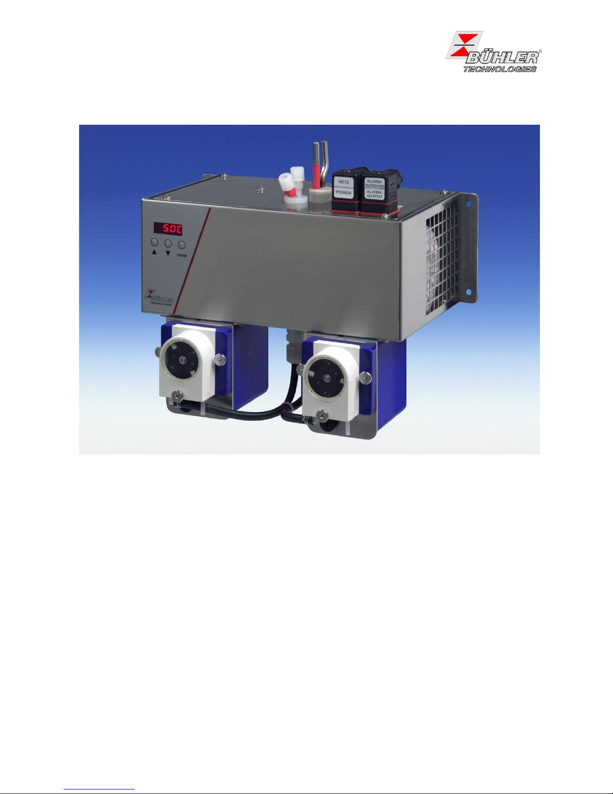
Die Kühler der Baureihe PKE 5xx sind zum Einsatz in Gasanalysensystemen bestimmt. Beachten Sie die
Angaben der Datenblätter hinsichtlich spezifischen Verwendungszwecks, vorhandener Werkstoffkombinationen sowie Druck- und Temperaturgrenzen.
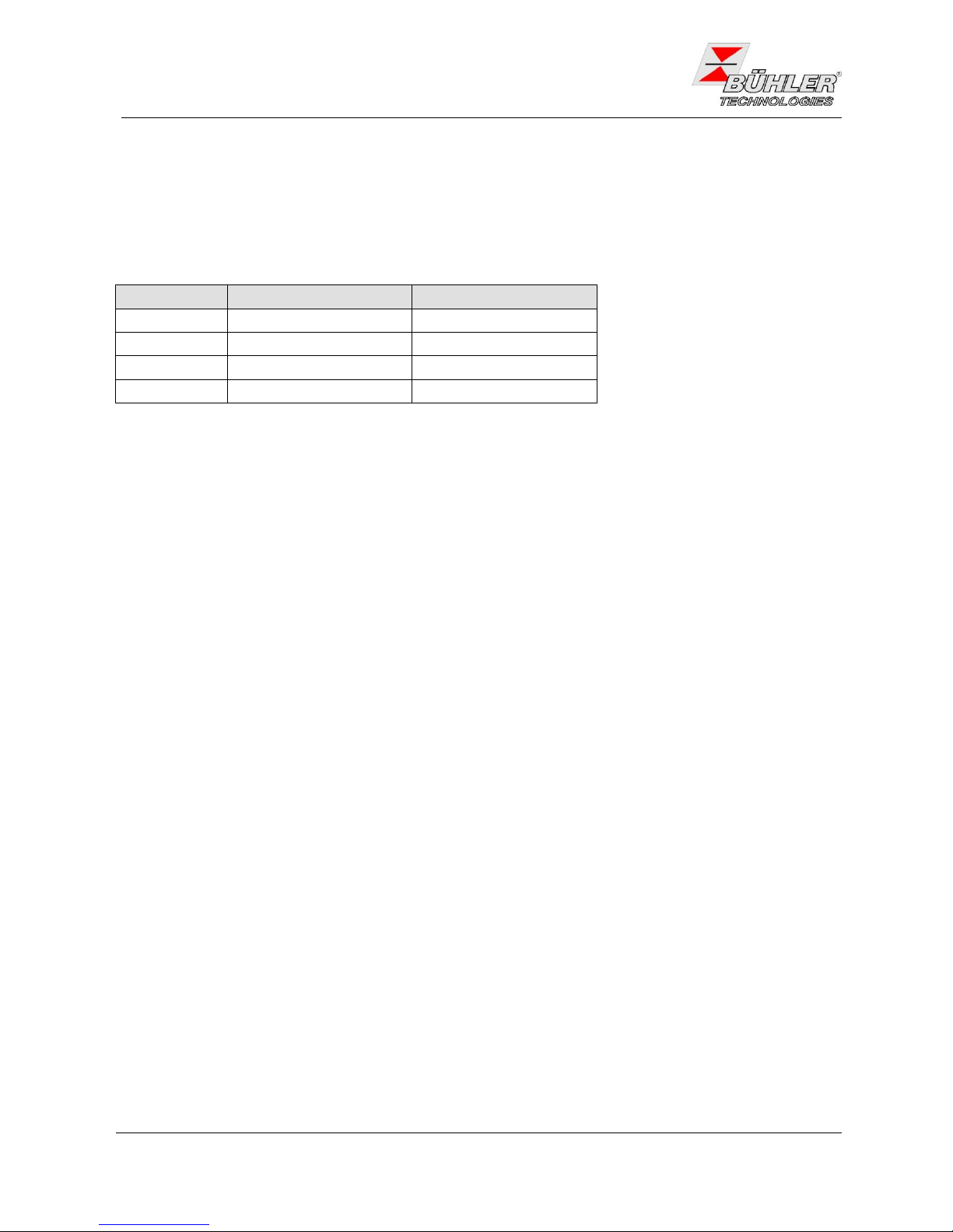
Die Baureihe PKE 5xx beinhaltet die nachfolgenden Typen. Den genauen Typen ersehen Sie aus dem
Typenschild auf dem Gerät bzw. aus der Elektronik (siehe dazu die Beschreibung des Menüs unter 4.)
Grundtyp
Umgebungstemperatur
Anzahl Wärmetauscher
PKE 511
+5…40 °C
1
PKE 521
+5…50 °C
1
PKE 512
+5…40 °C
2
PKE 522
+5…50 °C
2
Tabelle 1: Spezifikation PKE 5xx
2 Wichtige Hinweise
Bitte überprüfen Sie vor Einbau des Gerätes, ob die genannten technischen Daten den Anwendungsparametern entsprechen. Überprüfen Sie ebenfalls, ob alle zum Lieferumfang gehörenden Teile vollständig
vorhanden sind.
Der Einsatz der Geräte ist nur zulässig, wenn:
- das Produkt unter den in der Bedienungs- und Installationsanleitung beschriebenen Bedingungen, dem
Einsatz gemäß Typenschild und für Anwendungen, für die es vorgesehen ist, verwendet wird. Bei
eigenmächtigen Änderungen des Gerätes ist die Haftung durch die Bühler Technologies GmbH
ausgeschlossen.
- die im Datenblatt und der Anleitung angegebenen Grenzwerte eingehalten werden.
- Überwachungsvorrichtungen / Schutzvorrichtung korrekt angeschlossen sind.
- die Service- und Reparaturarbeiten, die nicht in dieser Anleitung beschrieben sind, von Bühler Technologies
GmbH durchgeführt werden.
- Originalersatzteile verwendet werden.
Diese Bedienungsanleitung ist Teil des Betriebsmittels. Der Hersteller behält sich das Recht vor, die
Leistungs-, die Spezifikations- oder die Auslegungsdaten ohne Vorankündigung zu ändern. Bewahren Sie die
Anleitung für den späteren Gebrauch auf.
Page 5
Bedienungs- und Installationsanleitung
Installation- and Operation Instruction
Messgaskühler / Sample Gas Coolers PKE-5xx
BX440010 08/2013 Art. Nr. 90 31 105
5
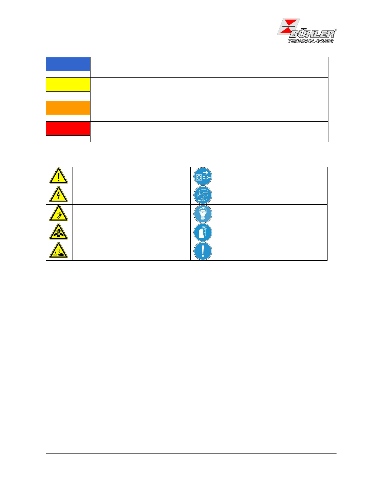
Signalwörter für Warnhinweise:
HINWEIS
Signalwort für wichtige Information zum Produkt, auf die im besonderen Maße
aufmerksam gemacht werden soll.
VORSICHT
Signalwort zur Kennzeichnung einer Gefährdung mit geringem Risiko, die zu einem
Sachschaden oder leichten bis mittelschweren Verletzungen führen kann, wenn sie nicht
vermieden wird.
WARNUNG
Signalwort zur Kennzeichnung einer Gefährdung mit mittlerem Risiko, die möglicherweise
Tod oder schwere Verletzungen zur Folge hat, wenn sie nicht vermieden wird.
GEFAHR
Signalwort zur Kennzeichnung einer Gefährdung mit hohem Risiko, die unmittelbar Tod
oder schwere Verletzung zur Folge hat, wenn sie nicht vermieden wird.
In dieser Anleitung werden folgende Warnzeichen und Signalwörter benutzt:
Warnung vor einer allgemeinen Gefahr
Gerät vom Netz trennen
Warnung vor gefährlicher Spannung
Gesichtsschutz tragen
Warnung vor einem elektrischen Schlag
Atemschutz tragen
Warnung vor Inhalation giftiger Gase
Handschuhe tragen
Warnung vor ätzenden Substanzen
Anweisung / Hinweis
beachten
2.1 Allgemeine Gefahrenhinweise
Das Gerät darf nur von Fachpersonal installiert werden, das mit den Sicherheitsanforderungen und den
Risiken vertraut ist.
Beachten Sie unbedingt die für den Einbauort relevanten Sicherheitsvorschriften und allgemein gültigen
Regeln der Technik. Beugen Sie Störungen vor und vermeiden Sie dadurch Personen- und Sachschäden.
Der für die Anlage Verantwortliche muss sicherstellen, dass:
- Sicherheitshinweise und Betriebsanleitungen verfügbar sind und eingehalten werden,
- Unfallverhütungsvorschriften der Berufsgenossenschaften beachtet werden; in Deutschland:
„Grundsätze der Prävention“ (BGV A1) und “Elektrische Anlagen und Betriebsmittel (BGV A3)”,
- die Prüfungen vor Inbetriebnahme und wiederkehrende Prüfungen nach Betriebssicherheitsverordnung
(BetrSichV) durchgeführt werden,
- Schutzeinrichtungen verwendet werden und vorgeschriebene Wartungsarbeiten durchgeführt werden,
- bei der Entsorgung die gesetzlichen Regelungen beachtet werden.
Wartung, Reparatur:
- Reparaturen an den Betriebsmitteln dürfen nur von Bühler autorisiertem Personal ausgeführt werden.
- Nur Umbau-, Wartungs- oder Montagearbeiten ausführen, die in dieser Bedienungs- und
Installationsanleitung beschrieben sind.
- Nur Original-Ersatzteile verwenden.
Bei Durchführung von Wartungsarbeiten jeglicher Art müssen die relevanten Sicherheits- und
Betriebsbestimmungen beachtet werden.
Page 6
Bedienungs- und Installationsanleitung
Installation- and Operation Instruction
Messgaskühler / Sample Gas Coolers PKE-5xx
6
BX440010 08/2013 Art. Nr. 90 31 105
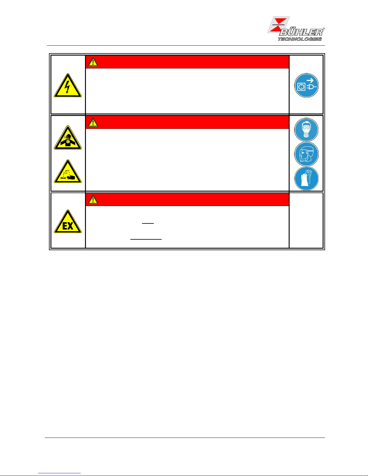
GEFAHR
Elektrische Spannung
Gefahr eines elektrischen Schlages.
Trennen Sie das Gerät bei allen Arbeiten vom Netz. Sichern Sie das Gerät
gegen unbeabsichtigtes Wiedereinschalten.
Das Gerät darf nur von instruiertem, fachkundigem Personal geöffnet werden.
GEFAHR
Giftige, ätzende Gase
Messgas kann gesundheitsgefährdend sein.
Bitte sorgen Sie ggf. für eine sichere Ableitung des Gases.
Schützen Sie sich bei der Wartung vor giftigen / ätzenden Gasen. Tragen Sie
die entsprechende Schutzausrüstung.
GEFAHR
Explosionsgefahr bei Verwendung in Explosionsgefährdeten Bereichen
Das Betriebsmittel ist nicht für den Einsatz in explosionsgefährdeten Bereichen
geeignet.
Durch das Gerät dürfen keine zündfähigen oder explosiven Gasgemische
geleitet werden.
Page 7

Bedienungs- und Installationsanleitung
Installation- and Operation Instruction
Messgaskühler / Sample Gas Coolers PKE-5xx
BX440010 08/2013 Art. Nr. 90 31 105
7
3 Aufbauen und Anschließen
Das Gerät ist für den Einsatz in geschlossenen Räumen vorgesehen. Beim Einsatz im Freien ist ein
ausreichender Wetterschutz vorzusehen.
Der Messgaskühler ist an die Wand zu montieren. Unterhalb des Gerätes muss genügend Raum zur Ableitung
des Kondensates vorhanden sein. Oberhalb ist etwas Platz für die Gaszuführung vorzusehen.
Es ist darauf zu achten, dass die zulässige Umgebungstemperatur eingehalten wird (siehe Tabelle 1 auf Seite
4). Die Konvektion des Kühlers darf nicht behindert werden. An den seitlichen Lüftungsöffnungen muss
ausreichend Platz zum nächsten Hindernis sein. Insbesondere auf der Luftauslassseite (rechts) muss die
Entfernung mindestens 10 cm betragen. Bei Montage in geschlossenen Gehäusen, z.B. Analysenschränken,
ist für eine ausreichende Entlüftung zu sorgen. Reicht die Konvektion nicht aus, empfehlen wir, den Schrank
mit Luft zu spülen oder einen Ventilator vorzusehen, um die Innentemperatur zu senken.
3.1 Montage
Bei Wärmetauschern aus Glas ist bei dem Anschluss der Gasleitungen auf die richtige Lage der Dichtung zu
achten. Die Dichtung besteht aus einem Silikonring mit einer Stulpe aus PTFE. Die PTFE-Seite muss zum
Glasgewinde zeigen.
PTFE
Glas
A000268
Die Gaszuführung ist zum Kühler mit Gefälle zu verlegen. Bei großem Kondensatanfall empfehlen wir, eine
Kondensatvorabscheidung vor dem Kühler einzusetzen. Hierzu eignen sich unsere Flüssigkeitsabscheider mit
automatischer Kondensatentleerung 11 LD spez., AK 20 oder Typ 165.
Die Gaseingänge sind rot markiert. Gehen Sie beim Anschluss der Glaswärmetauscher vorsichtig vor und
ziehen Sie die Verschraubungen nur von Hand an.
Für die Kondensatableitung stehen Glasgefäße und automatische Kondensatableiter zur Verfügung, die extern
unterhalb des Gerätes zu montieren sind. Bei Verwendung von automatischen Kondensatableitern muss die
Gaspumpe vor dem Kühler montiert werden, da sonst die Funktion der Kondensatableiter nicht mehr
gewährleistet ist.
Page 8
Bedienungs- und Installationsanleitung
Installation- and Operation Instruction
Messgaskühler / Sample Gas Coolers PKE-5xx
8
BX440010 08/2013 Art. Nr. 90 31 105
Hinweis
Die Wärmetauscher MTS und MTV (im Kühler mit 2 Wärmetauschern) können nicht in
Verbindung mit einem automatischen Kondensatableiter betrieben werden.
Befindet sich die Messgaspumpe am Ausgang des Kühlers (Saugbetrieb), ist der Einsatz von
Kondensatsammelgefäßen aus Glas oder der Einsatz von peristaltischen Pumpen zu empfehlen.
Anschluss der Kondensatableiter: je nach Werkstoff eine Verbindungsleitung aus Verschraubung und Rohr
oder Schlauch zwischen Wärmetauscher und Kondensatableiter herstellen. Bei Edelstahl kann der
Kondensatableiter direkt am Verbindungsrohr aufgehängt werden, bei Schlauchleitungen ist der
Kondensatableiter mittels einer Schelle separat zu befestigen. Kondensatleitungen sind grundsätzlich mit
Gefälle und Mindestnennweite DN 8/10 zu verlegen.
Bei Verwendung einer peristaltischen Pumpe kann diese auch etwas entfernt vom Kühler befestigt werden.
3.2 Elektrische Anschlüsse
WARNUNG
Der Anschluss darf nur von geschultem Fachpersonal vorgenommen werden.
VORSICHT
Falsche Netzspannung kann das Gerät zerstören
Bei Anschluss auf die richtige Netzspannung gemäß Typenschild achten
WARNUNG
Beschädigung des Gerätes bei Durchführung der Isolationsprüfung
Führen Sie keine Prüfung der Spannungsfestigkeit mit Hochspannung am Gesamtgerät
durch!
Das Gerät ist mit umfangreichen EMV-Schutzmaßnahmen ausgerüstet. Bei einer Prüfung der Spannungsfestigkeit werden elektronische Filterbauteile beschädigt. Die notwendigen Prüfungen wurden bei allen zu
prüfenden Baugruppen werkseitig durchgeführt (Prüfspannung je nach Bauteil 1 kV bzw. 1,5 kV).
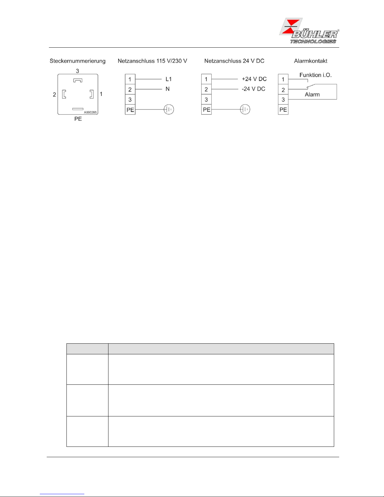
Die Messgaskühler PKE 5xx sind mit je einem Stecker nach DIN 43650 für die Spannungsversorgung und den
Statusausgang ausgerüstet. Diese sind bei korrektem Anschluss der Leitung verwechslungssicher angebracht.
Bitte achten Sie deshalb darauf, dass die Stecker nach dem Anschluss der Leitungen wieder entsprechend
zusammengebaut werden. Nachfolgend sind die Anschlussbelegungen angegeben, wobei die Nummern
denen auf den Steckern entsprechen.
Page 9
Bedienungs- und Installationsanleitung
Installation- and Operation Instruction
Messgaskühler / Sample Gas Coolers PKE-5xx
BX440010 08/2013 Art. Nr. 90 31 105
9
Ist der PKE 5xx mit peristaltischen Pumpen ausgestattet, müssen diese an eine separate Spannungsquelle
angeschlossen werden.
4 Betrieb und Wartung
4.1 Betrieb
Nach dem Einschalten des Kühlers sehen Sie die Anzeige der Blocktemperatur. Die Anzeige blinkt, solange
der (eingestellte) Temperaturbereich um den voreingestellten Ausgangstaupunkt noch nicht erreicht ist. Der
Statuskontakt ist in der Stellung Alarm.
Wird der Temperaturbereich erreicht, wird die Temperatur dauerhaft angezeigt und der Statuskontakt schaltet
um.
Sofern im laufenden Betrieb die Anzeige blinken sollte oder eine Fehlermeldung erscheint, betrachten Sie bitte
Gliederungspunkt 6.1 „Fehlersuche und Behebung“.
Die Leistungs- und Grenzdaten sind dem Datenblatt zu entnehmen.
4.2 Bedienung der Menüfunktionen
Kurzerklärung des Bedienungsprinzips:
Benutzen Sie diese Kurzerklärung nur, wenn Sie bereits Erfahrung im Bedienen des Peltierkühlers besitzen.
Eine ausführliche Erklärung erhalten Sie unter 4.2.2 und Kapitel 4.3.
Tasten:
Die Bedienung erfolgt mit nur 3 Tasten. Sie haben folgende Funktionen:
Taste
Funktionen
j
Wechsel von der Messwertanzeige ins Hauptmenü
Auswahl des angezeigten Menüpunktes
Annahme eines editierten Wertes oder einer Auswahl
t
Wechsel zum oberen Menüpunkt
Erhöhen der Zahl beim Ändern eines Wertes oder Wechseln der Auswahl
temporärer Wechsel zur alternativen Messwertanzeige (wenn Option vorhanden)
b
Wechsel zum unteren Menüpunkt
Erniedrigen der Zahl beim Ändern eines Wertes oder Wechseln der Auswahl
temporärer Wechsel zur alternativen Messwertanzeige (wenn Option vorhanden)
Page 10
Bedienungs- und Installationsanleitung
Installation- and Operation Instruction
Messgaskühler / Sample Gas Coolers PKE-5xx
10
BX440010 08/2013 Art. Nr. 90 31 105
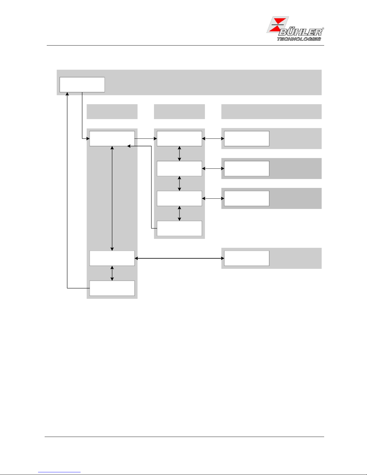
4.2.1 Übersicht der Menüführung
Anzeige der Temperatur und des Betriebszustandes
Peltierkühler
Anzeige: P5__
2°C...20°C
Anzeige: xxxx
Globale Einstellungen
Anzeige: toP
+1°C…+7C
Anzeige: xxx
Exit Hauptmenü
Anzeige: E
t b
Exit Untermenü
Anzeige: E
j
Hauptmenü
Solltemperatur
Anzeige: tEMP
Untermenü
Alarmhysterese
Anzeige: A Hi
Einstellbereich
Celsius/ Fahrenheit
Anzeige: C [F]
j
j
t b
t b
t b
j
j
j
j
aktuelle Temperatur
Anzeige: xxxx
Angezeigt wird die Kühlertemperatur in 0,5°C Schritten. Durch betätigen der Enter Taste gelangt man ins
Hauptmenü. Die Temperatur kann wahlweise in Celsius oder in Fahrenheit dargestellt werden.
Einstellung der
Kühlertemperatur im
Bereich: 2°C...20°C
Setzen der oberen
Alarmgrenze im Bereich:
+1°C...+7°C
Einstellen der Anzeigeneinheit. Wahlweise
Celsius oder Fahrenheit
t b Wert einstellen
j speichert den Wert
warte 4s: kein speichern
-1°C…-3C
Anzeige: xxx
Alarmhysterese
Anzeige: A Lo
j
t b
Setzen der unteren
Alarmgrenze im Bereich:
-1°C...-3°C
VD 00 0001
Abb. 1 Menüübersicht
Page 11
Bedienungs- und Installationsanleitung
Installation- and Operation Instruction
Messgaskühler / Sample Gas Coolers PKE-5xx
BX440010 08/2013 Art. Nr. 90 31 105
11
4.2.2 Ausführliche Erklärung des Bedienungsprinzips
Die ausführliche Erklärung führt Sie Schritt für Schritt durch das Menü des Peltierkühlers.
Schließen Sie den Peltierkühler an die Stromversorgung an und warten Sie die Einschaltprozedur ab.
Zu Beginn wird für kurze Zeit die im Gerät implementierte Software-Version angezeigt. Anschließend
geht das Gerät direkt zur Messwertanzeige über.
Durch Drücken der Taste j gelangt man vom Anzeigemodus ins Hauptmenü. (Es ist gewährleistet,
dass die Steuerung auch im Menübetrieb weiter läuft.)
Man navigiert mit den Tasten t b gemäß Abb. 1 durch das Hauptmenü.
Bestätigt man einen Hauptmenüeintrag (j), wird das zugehörige Untermenü aufgerufen.
Hier können Betriebsparameter eingestellt werden. Zum Einstellen der Parameter durchläuft man das
Untermenü mit den Tasten t b und bestätigt mit j den einzustellenden Menüpunkt.
Nun können die Werte innerhalb bestimmter Grenzen durch Betätigen der t b Tasten verstellt
werden. Bestätigt man die Einstellung mit j, wird der eingestellte Wert vom System gespeichert. Im
Anschluss gelangt man automatisch zurück ins Untermenü.
Da ein manuelles Rückspringen aus den einstellbaren Bereichen nicht vorgesehen ist, kann einfach
einige Sekunden gewartet werden. Das System wechselt dann zurück ins Untermenü.
Ähnlich verhält es sich mit dem Unter- oder auch mit dem Hauptmenü. Falls vergessen wird, das
Menü regulär zu verlassen, wechselt das System selbstständig zurück in den Anzeigemodus ohne die
Werte zu speichern. Dabei werden hier allerdings die zuvor gespeicherten Parameter beibehalten und
nicht wieder zurückgesetzt. Hinweis: Sobald Werte mit der Enter-Taste gespeichert werden, werden
diese für die Reglung übernommen.
Verlassen des Haupt- bzw. Untermenüs erfolgt durch Auswahl des Menüpunktes E (Exit).
4.3 Beschreibung der Menüfunktionen
4.3.1 Hauptmenü
Peltierkühler (PKE 5xx)
Peltierkühler:
Von hier aus gelangt man zu allen relevanten Einstellmöglichkeiten des
Peltierkühlers. Im zugehörigen Untermenü können Solltemperatur und die
Alarmschwellen ausgewählt werden.
Globale Einstellung (ToP Settings)
Top Settings
Auswahl der globalen Temperatureinheit. Wahlweise Grad Celsius (C) oder
Grad Fahrenheit (F)
Hinweis:
Zu diesem Hauptmenüpunkt gibt es keinen Untermenüpunkt. Es kann von hier
aus direkt die Temperatureinheit ausgewählt werden.
Exit Hauptmenü
Exit
Durch Auswählen gelangt man zurück in den Anzeigemodus.
Page 12
Bedienungs- und Installationsanleitung
Installation- and Operation Instruction
Messgaskühler / Sample Gas Coolers PKE-5xx
12
BX440010 08/2013 Art. Nr. 90 31 105
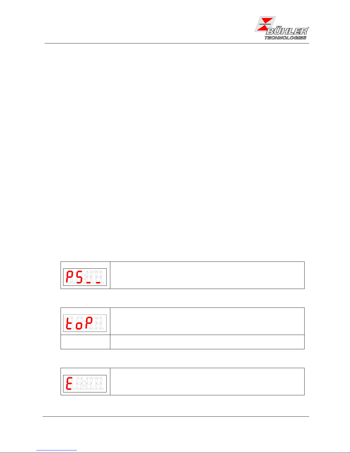
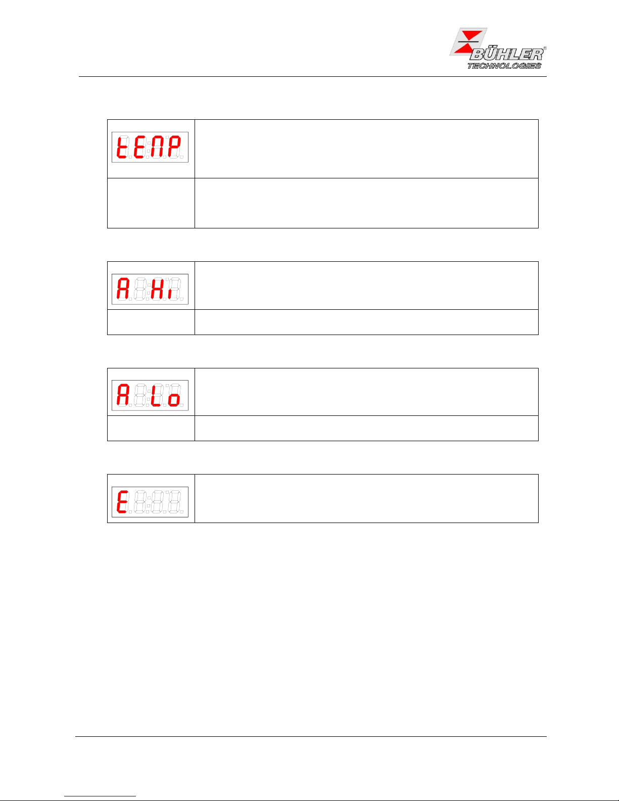
4.3.2 Untermenü Peltierkühler (Anzeige: P5__)
Peltierkühler Solltemperatur (temperature)
Temperatur
Diese Einstellung setzt den Sollwert für die Kühlertemperatur. Der Wert kann in
einem Bereich von 2°C (35.6°F) bis 20°C (68°F) gesetzt werden.
Hinweis:
Der Standardwert bei Auslieferung beträgt 5°C (41°F) (solange nichts anderes
vereinbart).
Bei geänderter Temperatur blinkt die Anzeige gegebenenfalls, bis der neue
Arbeitsbereich erreicht ist
Peltierkühler obere Alarmgrenze (Alarm high)
Alarm high
Hier kann der obere Schwellwert für den optischen Alarm sowie für das
Alarmrelais gesetzt werden. Eingestellt wird die Alarmgrenze im Bereich von
+1°C (+1.8°F) bis +7°C (+13°F) bezogen auf die eingestellte Kühlertemperatur.
Hinweis:
Der Standardwert bei Auslieferung beträgt +3°C (+5°F) (solange nichts anderes
vereinbart ist).
Peltierkühler untere Alarmgrenze (Alarm low)
Alarm Low
Hier kann der untere Schwellwert für den optischen Alarm sowie für das
Alarmrelais gesetzt werden. Eingestellt wird die Alarmgrenze im Bereich von 1°C (-1.8°F) bis -3°C(-5°F) bezogen auf die eingestellte Kühlertemperatur.
Hinweis:
Der Standardwert bei Auslieferung beträgt -3°C(-5°F) (solange nichts anderes
vereinbart ist).
Exit Untermenü
Exit
Durch Auswählen gelangt man zurück ins Hauptmenü.
4.4 Wartung
Spezielle Wartungsarbeiten sind beim Standardgaskühler nicht erforderlich.
Ist der PKE 5xx mit peristaltischen Pumpen ausgestattet, ist deren Verschlauchung je nach Art des Gases in
regelmäßigen Abständen zu überprüfen. Zum Austausch der Schläuche siehe Anhang 6.6.
Page 13

Bedienungs- und Installationsanleitung
Installation- and Operation Instruction
Messgaskühler / Sample Gas Coolers PKE-5xx
BX440010 08/2013 Art. Nr. 90 31 105
13
5 Instandsetzung, Entsorgung
5.1 Fehlerbehebung
Sollte ein Fehler beim Betrieb auftreten, finden Sie unter Gliederungspunkt 6. Hinweise für die Fehlersuche
und Beseitigung.
Sollten Sie weitere Fragen haben, wenden Sie sich bitte an unseren Service
Tel.: +49-(0)2102-498955 oder Ihre zuständige Vertretung.
Ist nach Beseitigung eventueller Störungen und nach Einschalten der Netzspannung die korrekte Funktion
nicht gegeben, muss das Gerät durch den Hersteller überprüft werden. Bitte senden Sie das Gerät zu diesem
Zweck in geeigneter Verpackung an:
Bühler Technologies GmbH
- Reparatur/Service Harkortstraße 29
40880 Ratingen
Deutschland
Bringen Sie zusätzlich die Dekontaminierungserklärung ausgefüllt und unterschrieben an der Verpackung an.
Ansonsten ist eine Bearbeitung Ihres Reparaturauftrages nicht möglich! Das Formular kann per E-Mail
angefordert werden: service@buehler-technologies.com.
5.2 Entsorgen
Bei der Entsorgung sind die gesetzlichen Vorschriften, insbesondere für die Entsorgung von elektronischen
Bauteilen, zu beachten.
Page 14
Bedienungs- und Installationsanleitung
Installation- and Operation Instruction
Messgaskühler / Sample Gas Coolers PKE-5xx
14
BX440010 08/2013 Art. Nr. 90 31 105
6 Anhang
6.1 Fehlersuche und Beseitigung
Problem / Störung
mögliche Ursache
Abhilfe
Keine Anzeige
- Netzspannung unterbrochen
- Netzanschluss vornehmen; Sitz
des Netzsteckers überprüfen
- Sicherung defekt
- Sicherung überprüfen u. ggf.
wechseln
Alarm-LED blinkt bei
- Übertemperatur
- Arbeitspunkt noch nicht erreicht
- Warten (max. 20 min)
- Kühlleistung zu gering, obwohl der
Kühler arbeitet
- Unbedingt darauf achten, dass
Lüftungsschlitze nicht verdeckt
werden (Wärmestau)
- Zu große Durchflussmenge / zu
hoher Taupunkt / Gastemperatur
- Grenzparameter einhalten /
Vorabscheider vorsehen
- Stillstand des eingebauten
Ventilators
- überprüfen, ggf. austauschen
- Untertemperatur
- Regelung defekt
- Kühler einsenden
Fehlermeldungen im Display
Error 01
- Unterbrechung
- Temperaturfühler defekt: Kühler
einsenden
Error 02
- Kurzschluss
- Temperaturfühler defekt: Kühler
einsenden
Kondensat im Gasausgang
- Kondensatsammelgefäß voll
- Kondensatsammelgefäß entleeren
- Evtl. Festsitzen des Ventils im
autom. Kondensatableiter
- In beide Richtungen spülen
- Kühler überlastet
- Grenzparameter einhalten
Verminderter Gasdurchsatz
- Gaswege verstopft
- Wärmetauscher demontieren und
reinigen
- Kondensatausgang vereist
- Kühler einsenden
Page 15

Bedienungs- und Installationsanleitung
Installation- and Operation Instruction
Messgaskühler / Sample Gas Coolers PKE-5xx
BX440010 08/2013 Art. Nr. 90 31 105
15
6.2 Warnhinweise
HINWEIS
Der Anschluss darf nur von geschultem Fachpersonal vorgenommen werden. Achten Sie auf
die korrekte Spannungsversorgung
Der Gaskühler darf nicht außerhalb seiner Spezifikationen betrieben werden.
Bei Durchführung von Umbau-, Wartungs- oder Montagearbeiten jeglicher Art müssen die
relevanten Sicherheits- und Betriebsbestimmungen beachtet werden.
Führen Sie nur Umbau-, Wartungs- oder Montagearbeiten aus, die in dieser Bedienungs- und
Installationsanleitung beschrieben sind.
Nicht in dieser Anleitung beschriebene Reparaturen an dem Gaskühler dürfen nur von Bühler
autorisiertem Personal ausgeführt werden.
Verwenden Sie nur Original-Ersatzteile.
GEFAHR
Gefährliche Spannung
Elektrischer Schlag
Trennen Sie bei Wartungs- und Reparaturarbeiten die elektrischen
Betriebsmittel vom Stromnetz. Stellen Sie sicher, dass die Betriebsmittel nicht
unbeabsichtigt wieder unter Spannung gesetzt werden können.
GEFAHR
Giftige / ätzende Gase und Flüssigkeiten
Vergiftung, Verätzung von Haut, Augen und Lungen möglich
Schützen Sie sich vor giftigen / ätzenden Gasen und Flüssigkeiten. Tragen Sie
Handschuhe, Atem- und Gesichtsschutz.
Page 16

Bedienungs- und Installationsanleitung
Installation- and Operation Instruction
Messgaskühler / Sample Gas Coolers PKE-5xx
16
BX440010 08/2013 Art. Nr. 90 31 105
6.3 Auswechseln der Feinsicherung im Messgaskühler
6.3.1 115 V und 230 V
Kühler von der Netzspannung trennen!
Lösen Sie die 8 Schrauben, die den Deckel auf dem Gehäuse
halten. Wenn an den Kühler Schlauchpumpen angebracht sind,
müssen diese abgebaut werden, da diese mit den
Gehäuseschrauben befestigt sind.
Nehmen Sie vorsichtig den Deckel ab. Achtung: Die Anzeige ist am
Deckel befestigt und mit der Elektronik auf dem Grundkörper
verbunden. Die Steckverbindung kann zum Ablegen des Deckels
gelöst werden.
Die Sicherung befindet sich auf der kleinen Netzplatine unter einer
Plastikkappe. Sicherung austauschen und Kappe wieder
Aufdrücken. Beachten Sie die Netzspannung für die Auswahl der
richtigen Sicherung.
Steckverbindung wieder herstellen und Deckel wieder aufsetzen.
Befestigungsschrauben einschrauben bzw. Pumpen wieder
montieren.
Spannungsversorgung wieder herstellen.
6.3.2 24 V DC
Kühler von der Netzspannung trennen!
Lösen Sie die 8 Schrauben, die den Deckel auf dem Gehäuse halten.
Nehmen Sie vorsichtig den Deckel ab. Achtung: Die Anzeige ist am
Deckel befestigt und mit der Elektronik auf dem Grundkörper
verbunden. Die Steckverbindung kann zum Ablegen des Deckels
gelöst werden.
Die Sicherung befindet sich im Sicherungshalter (siehe Bild). Öffnen
Sie diesen durch Drehen und tauschen Sie die Sicherung aus.
Beachten Sie die Netzspannung für die Auswahl der richtigen
Sicherung.
Steckverbindung wieder herstellen und Deckel wieder aufsetzen.
Befestigungsschrauben einschrauben.
Spannungsversorgung wieder herstellen.
Page 17

Bedienungs- und Installationsanleitung
Installation- and Operation Instruction
Messgaskühler / Sample Gas Coolers PKE-5xx
BX440010 08/2013 Art. Nr. 90 31 105
17
6.4 Demontage und Reinigung des Wärmeaustauschers
Wärmetauscher müssen nur ausgetauscht oder gewartet werden, wenn sie verstopft oder beschädigt sind.
Sollten sie sich zugesetzt haben, empfehlen wir zu prüfen, ob sich dies in Zukunft durch den Einsatz eines
Filters vermeiden lässt.
Gaszufuhr sperren.
Gerät ausschalten und Netzstecker ziehen.
Gasverbindungen und Kondensatablauf lösen.
Wärmetauscher nach oben herausziehen.
Kühlnest (Loch im Kühlblock) reinigen.
Wärmetauscher spülen, bis alle Verunreinigungen beseitigt sind.
Wärmetauscher an der gekühlten Außenfläche mit Silikonfett einschmieren.
Wärmetauscher mit drehender Bewegung in das Kühlnest wieder einschieben.
Gasverbindung und Kondensatablauf wiederherstellen.
6.5 Auswechseln der Feinsicherung der peristaltischen Pumpe
Pumpe von der Spannungsversorgung trennen.
Isolationskappe vom Sicherungshalter am Befestigungswinkel der Pumpe abnehmen. Hierzu die
Kappe mit einem Schlitzschraubendreher eindrücken und eine Vierteldrehung nach links drehen.
Sicherung austauschen und Kappe durch Andrücken und Rechtsdrehung wieder aufsetzen.
Spannungsversorgung wieder herstellen.
6.6 Austausch des Schlauches der peristaltischen Pumpe (wenn
Pumpe vorhanden)
Gaszufuhr sperren.
Gerät ausschalten und Netzstecker ziehen.
Zu- und Abführungsschlauch an der Pumpe entfernen (Sicherheitshinweise beachten!)
Mittlere Rändelschraube lösen, aber nicht ganz abdrehen. Schraube nach unten klappen.
Abdeckkappe abziehen.
Anschlüsse seitlich herausziehen und Schlauch entfernen.
Schlauch wechseln und zur Montage obige Schritte in umgekehrter Reihenfolge durchführen.
Page 18

Bedienungs- und Installationsanleitung
Installation- and Operation Instruction
Messgaskühler / Sample Gas Coolers PKE-5xx
18
BX440010 08/2013 Art. Nr. 90 31 105
6.7 Ersatzteile und Zusatzteile
Bei Ersatzteilbestellungen bitten wir Sie, Kühlertyp und Seriennummer anzugeben.
Bauteile für Nachrüstung und Erweiterung finden Sie im angehängten Datenblatt und in unserem Katalog.
Die folgenden Ersatzteile sollten vorgehalten werden:
Ersatzteil
Artikel-Nr.
Ersatzschlauch für peristaltische Pumpe 0,3 l/h
(nur notwendig, wenn Pumpe eingebaut)
91 240 30 027
Feinsicherung Messgaskühler
230 V
5x20mm, 1,25 A träge
91 100 00 058
115 V
5x20mm, 2,5 A träge
91 100 00 013
24 V DC
5x20 mm, 6,3 A träge
91 100 00 063
Feinsicherung peristaltische Pumpe
230 V / 115 V
5x20 mm, 1 A flink
91 100 00 061
Anzeige ABT 400
91 000 10 124
Controller Platine MCP1
91 000 10 125
Reglerplatine PKE
91 000 10 126
Netzanschlussplatine
91 000 10 127
6.8 Beiliegende Unterlagen
- Datenblatt PKE 5xx: DD 44 0012
- Konformitätserklärungen: KX 44 0002
- Dekontaminierungserklärung
Page 19

Bedienungs- und Installationsanleitung
Installation- and Operation Instruction
Messgaskühler / Sample Gas Coolers PKE-5xx
BX440010 08/2013 Art. Nr. 90 31 105
19
1 Introduction
The sample gas coolers of model range PKE 5xx are designed for applications in gas analysis systems. It is a
very important item in a sample conditioning system. Hence it is essential to read carefully the enclosed data
sheet and check that all application parameters are completely matched by the gas cooler.
The model range of PKE 5xx consists of the types listed below. The exact type follows from the type plate on
the device and the electronics, respectively (see also menu description in chapter 4.2)
Basic type
ambient temperature
number of heat exchangers
PKE 511
+5…40°C
1
PKE 521
+5…50°C
1
PKE 512
+5…40°C
2
PKE 522
+5…50°C
2
Table 1: Specifications of PKE 5xx
2 Important Advice
Please check prior to installation of the device that the technical data matches the application parameters.
Check that the delivery is complete as well.
Operation of the device is only valid if
- the product is used under the conditions described in the installation- and operation instruction, the intended
application according to the type plate and the intended use. In case of unauthorized modifications done by
the user Bühler Technologies GmbH can not be held responsible for any damage,
- the performance limits given in the datasheets and in the installation- and operation instruction are obeyed,
- monitoring devices and safety devices are installed properly,
- service and repair is carried out by Bühler Technologies GmbH, unless described in this manual,
- only original spare parts are used.
This manual is part of the equipment. The manufacturer keeps the right to modify specifications without
advanced notice. Keep this manual for later use.
Signal words for warnings:
NOTE
Signal word for important information to the product
CAUTION
Signal word for a hazardous situation with low risk, resulting in damage to the device or the
property or minor or medium injuries if not avoided.
WARNING
Signal word for a hazardous situation with medium risk, possibly resulting in severe injuries
or death if not avoided.
DANGER
Signal word for an imminent danger with high risk, resulting in severe injuries or death if
not avoided
Page 20

Bedienungs- und Installationsanleitung
Installation- and Operation Instruction
Messgaskühler / Sample Gas Coolers PKE-5xx
20
BX440010 08/2013 Art. Nr. 90 31 105
The following warning signs and signal words are used in this manual:
hazardous situation
disconnect from mains supply
hazardous voltage
wear face protector
electrical shock
wear respirator
toxic gases
wear gloves
corrosive Substances
Follow note
2.1 General Indication of Risk
Installation of the device shall be performed by trained staff only, familiar with the safety requirements and
risks.
Check all relevant safety regulations and technical indications for the specific installation place. Prevent failures
and protect persons against injuries and the device against damage.
The person responsible for the system must secure that:
- safety and operation instructions are accessible and followed,
- local safety regulations and standards are obeyed,
- performance data and installation specifications are regarded,
- safety devices are installed and recommended maintenance is performed,
- national regulations for disposal of electrical equipment are obeyed.
Maintenance and repair
- Repairs on the device must be carried out by Bühler authorized persons only.
- Only perform modifications, maintenance or mounting described in this manual.
- Only use original spare parts.
During maintenance regard all safety regulations and internal operation instructions.
Page 21

Bedienungs- und Installationsanleitung
Installation- and Operation Instruction
Messgaskühler / Sample Gas Coolers PKE-5xx
BX440010 08/2013 Art. Nr. 90 31 105
21
DANGER
Electrical voltage
Electrocution hazard.
Disconnect the device from power supply. Make sure that the equipment cannot
be reconnected to mains unintentionally.
The device must be opened by trained staff only.
DANGER
Toxic and corrosive gases
Sample gas can be hazardous.
Take care that the gas is exhausted in a place where no persons are in danger.
Protect yourself during maintenance against toxic / corrosive gases. Use gloves,
respirator and face protector under certain circumstances.
DANGER
Explosion hazard if used in hazardous areas
The device is not suitable for operation in hazardous areas with potentially
explosive atmospheres.
Do not expose the device to combustible or explosive gas mixtures.
Page 22

Bedienungs- und Installationsanleitung
Installation- and Operation Instruction
Messgaskühler / Sample Gas Coolers PKE-5xx
22
BX440010 08/2013 Art. Nr. 90 31 105
3 Installation and Connection
The PKE 5xx coolers are designed for indoors applications. If the device is installed outside provide sufficient
weather protection.
The PKE 5xx sample cooler is to be attached to vertical panels. Provide enough space below the device to
drain off condensate. Above leave some space for providing gas flow.
The allowed ambient temperature shall not exceed the values according to Table 1 on page 19. Free air
circulation must be provided. Leave enough space to any obstacle to the lateral ventilation grilles. Particularly
with regard to the air outlet (on the right) keep a gap of at least 10 cm (4 inches). If the device is mounted
inside closed covers, e.g. cabinets for gas analysis systems, provide adequate air circulation. If convection
alone is not sufficient, rinse the cabinet with air or install additional fans to lower the inner temperature.
3.1 Mounting
With glass heat exchangers, make sure that the gasket is inserted in correct orientation. The gasket consists
of a silicon ring and a PTFE shield. The PTFE shield must point to the glass thread.
PTFE
Glass
A000268
Make sure that all sample gas lines leading to the cooler are installed with a downward slope. In some
applications with very high condensate content separators upstream the cooler could become necessary. Best
suited are our fluid separators with automatic condensate drain 11 LD, especially AK20 or type 165.
The gas entrance is marked with red. Connect the hoses to the heat exchangers made of DURAN glass with
care to avoid breaking the glass.
To drain condensate glass vessels or automatic condensate drains are provided for external mounting below
the device. If the sample gas pump is located upstream of the cooler, the condensate can be drained off by
automatic condensate drains.
NOTE
Heat exchangers MTS and MTV (cooler with two heat exchangers) cannot be used with
automatic condensate drains.
Page 23

Bedienungs- und Installationsanleitung
Installation- and Operation Instruction
Messgaskühler / Sample Gas Coolers PKE-5xx
BX440010 08/2013 Art. Nr. 90 31 105
23
If the sample gas pump is installed downstream the cooler, we recommend using glass condensate vessels or
peristaltic pumps.
Mounting the condensate drains: depending on the used material the condensate drain may be connected to
the heat exchanger directly by stainless steel pipes or hoses. The condensate drains can be attached directly
to such coolers with stainless steel heat exchangers. In case of glass heat exchangers the condensate drains
must be connected with flexible hoses and fixed with by brackets separately. The condensate lines must be
installed with considerable slope and should not have less than 8 mm (0.3 inch) inner diameter.
If peristaltic pumps are used, they may be installed in some distance from the cooler.
3.2 Electrical Connection
WARNING
The device must be installed by trained staff only.
CAUTION
Wrong mains voltage may damage the device.
Regard the correct mains voltage as given on the type plate.
WARNING
Damage to the device in case of insulation testing
Do not proceed insulation tests with high voltage to the device as a whole.
The device is equipped with extensive EMC protection. If insulation tests are carried out the electronic filter
devices will be damaged. All necessary tests have been carried out for all concerned groups of components at
the factory (test voltage 1 kV or 1.5 kV respectively, depending on the device).
The PKE5xx is equipped with two connectors on top of the unit. One connector is for the power supply and the
other one for the alarm output. They cannot be interchanged and must be wired according to the following
diagram (numbering can be found on the connectors). Make sure they are correctly refitted after wiring.
If the PKE 5xx is equipped with peristaltic pumps, they must be connected to a separate power supply.
Page 24

Bedienungs- und Installationsanleitung
Installation- and Operation Instruction
Messgaskühler / Sample Gas Coolers PKE-5xx
24
BX440010 08/2013 Art. Nr. 90 31 105
4 Operation and Maintenance
4.1 Operation
After turning on the power supply the display shows the actual temperature of the cooling block. The display
blinks until the (set) temperature range with respect to the preset output dew point is reached. The status
contact is switched to “Alarm”.
If the temperature range is reached, the actual temperature is shown constantly and status contact switches
back.
If the display starts blinking during operation or an error message is displayed see chapter 6.1
“Troubleshooting”.
For performance limits see datasheet.
4.2 Operation of Menu Functions
Overview of the operational principal:
Use this short description if you have experience with Peltier coolers.
You will find detailed description in chapter 4.2.2 and chapter 4.1.
Keys:
Operation is carried out by only the keys with the following functions:
Key
Function
j
Switch from measurement display to main menu
Selection of the display menu item
Accepting the changed value or selection
t
Switch to the upper menu item
Increase of the value of switching the selection
Temporary display of the alternative measurement display (if option is installed)
b
Switch to lower menu item
Decrease of the value of switching the selection
Temporary display of the alternative measurement display (if option is installed)
Page 25

Bedienungs- und Installationsanleitung
Installation- and Operation Instruction
Messgaskühler / Sample Gas Coolers PKE-5xx
BX440010 08/2013 Art. Nr. 90 31 105
25
4.2.1 Overview of the Menu Items
Display of current temperature and operating state
Peltier Gas Cooler
Display: P5__
2°C...20°C
Display: xxxx
Global Settings
Display: toP
+1°C…+7C
Display: xxx
Exit Main Menu
Display: E
t b
Exit Submenu
Display: E
j
Main Menu
Set Temperature
Display: tEMP
Submenu
upper alarm threshold
Display: A Hi
Setting Range
Celsius/ Fahrenheit
Display: C [F]
j
j
t b
t b
t b
j
j
j
j
Current Temperature
Display: xxxx
Displayed is the block temperature with a resolution of 0.5°C. By pressing the Enter button brings the display to
the Main Menu. The unit of temperature is adjustable in the menu Global settings (Celsius or Fahrenheit).
Adjust the set point:
2°C...20°C
Set the upper alarm
Threshold above setpoint:
tEMP +1°C...+7°C
Set unit to Celsius or
Fahrenheit.
-1°C…-3C
Display: xxx
lower alarm threshold
Display: A Lo
j
t b
Set the lower alarm
Threshold below setpoint:
tEMP -1°C...-3°C
t b adjust value
j store value
wait 4s: no storage
VE 00 0001
Fig. 1: Overview of the menu
Page 26

Bedienungs- und Installationsanleitung
Installation- and Operation Instruction
Messgaskühler / Sample Gas Coolers PKE-5xx
26
BX440010 08/2013 Art. Nr. 90 31 105
4.2.2 Detailed Description of the operational Principle
This detailed description leads you through the menu for the cooler step by step.
Connect the cooler to the power supply and wait until the power-up sequence has finished. First the
version of the implemented software is displayed for a short time. Then the device switches to the
measurement display.
Pressing the j key switches from display-mode to main menu. (It is guaranteed that the control
continues during setting-mode.)
You can navigate through the main menu using the t b keys according to Fig. 1.
To accept the menu item press j and the related submenu is activated.
Now the parameters may be set. To change the parameters scroll the submenu using the keys t b
and confirm the selected menu item with
The values can be changes within their limits using the keys t b. Pressing the enter key (j) stores
the set value. Afterwards the device returns to the submenu automatically.
Wait for a few seconds without pressing any key to return to the submenu without saving the values.
The same procedure holds for the sub- and main menu. If you forget to quit the menu, the system
returns automatically to display mode. In this case the preset values are kept instead of being reset.
Note: As soon as the values are saved by pressing the enter key, they are accepted for regulation.
Quit the main menu or the submenu by selecting the menu item E (Exit)
4.3 Description of the Menu Functions
4.3.1 Main Menu
Peltier cooler (PKE 5xx)
Peltier cooler:
This item allows all relevant settings for the Peltier cooler. In the corresponding
submenu nominal temperature and alarm limits may be selected.
Global settings (toP settings)
Top settings
Selection of the global temperature unit, either degree Celsius (C) or degree
Fahrenheit (F)
Note:
This menu item has no sub-item. The temperature unit is directly selected.
Exit main menu
Exit
Selecting this item returns to the display mode.
Page 27

Bedienungs- und Installationsanleitung
Installation- and Operation Instruction
Messgaskühler / Sample Gas Coolers PKE-5xx
BX440010 08/2013 Art. Nr. 90 31 105
27
4.3.2 Submenu Peltier cooler (Display: P5__)
Peltier cooler Nominal temperature
Temperature
This item allows setting of the nominal temperature for the cooler. The value can
be set within a range from 2°C (35.6°F) to 20°C (68°F).
Note:
Default value at delivery is 5°C (41°F) (unless otherwise agreed).
Peltier cooler upper alarm threshold (Alarm high)
Alarm high
This item allows setting of the upper alarm threshold for the optical alarm as well
as for the alarm relay. The upper alarm threshold may be set in the range from
+1°C (+1.8°F) to +7°C (+13°F) above the nominal temperature.
Note:
Default value at delivery is +3°C (+5°F) (unless otherwise agreed).
Peltier cooler lower alarm threshold (Alarm low)
Alarm low
This item allows setting of the lower alarm threshold for the optical alarm as well
as for the alarm relay. The lower alarm threshold may be set in the range from 1°C (-1.8°F) to -3°C (-5°F) below the nominal temperature.
Note:
Default value at delivery is -3°C (-5°F) (unless otherwise agreed).
Exit submenu
Exit
Selecting this item returns to the main menu.
4.4 Maintenance
Basic versions of the cooler run maintenance free.
If the PKE 5xx is equipped with a peristaltic pump, the hoses have to be checked in regular intervals depending
on the gas. Displacement of the hoses is described in chapter 6.4.
Page 28

Bedienungs- und Installationsanleitung
Installation- and Operation Instruction
Messgaskühler / Sample Gas Coolers PKE-5xx
28
BX440010 08/2013 Art. Nr. 90 31 105
5 Repair and Disposal
5.1 Repair
If the device shows irregularities see chapter 6 for troubleshooting.
If you need help or more information
call +49(0)2102-498955 or your local agent.
If the device doesn’t work correctly after elimination of failures and turning power on, the device must be
checked by the manufacturer. Please ship the device with suitable packing to
Bühler Technologies GmbH
- Service Harkortstraße 29
40880 Ratingen
Germany
In Addition, attach the filled in and signed Declaration of Decontamination status to the packing. Otherwise,
your repair order cannot be processed! The form can be requested by e-mail to service@buehler-
technologies.com.
5.2 Disposal
Regard the local regulations for disposal of electric and electronic equipment.
Page 29

Bedienungs- und Installationsanleitung
Installation- and Operation Instruction
Messgaskühler / Sample Gas Coolers PKE-5xx
BX440010 08/2013 Art. Nr. 90 31 105
29
6 Appendices
6.1 Safety Instructions
NOTE
Trained staff only shall install the device. Check for correct supply voltage.
The cooler must not be operated out of the range of its specifications.
Regard the corresponding safety and operation regulations during maintenance or servicing.
Only perform modifications, servicing or mounting described in this manual.
Any manipulation on the gas cooler which is not described in this manual should only be
executed by Bühler authorised staff.
Only use original spare parts.
DANGER
Hazardous voltage
Electrocution hazard
Before any manipulation on the device, disconnect the electrical equipment from
the main power supply. Make sure that the electrical equipment cannot be
reconnected during repair or maintenance. The wiring must be done by trained
staff only.
DANGER
Toxic / corrosive gases and liquids
Poisoning, chemical burn of skin, eyes and lungs possible
Protect yourself against toxic / corrosive gases and liquids. If necessary wear
protection gloves, respirator and face protector.
Page 30

Bedienungs- und Installationsanleitung
Installation- and Operation Instruction
Messgaskühler / Sample Gas Coolers PKE-5xx
30
BX440010 08/2013 Art. Nr. 90 31 105
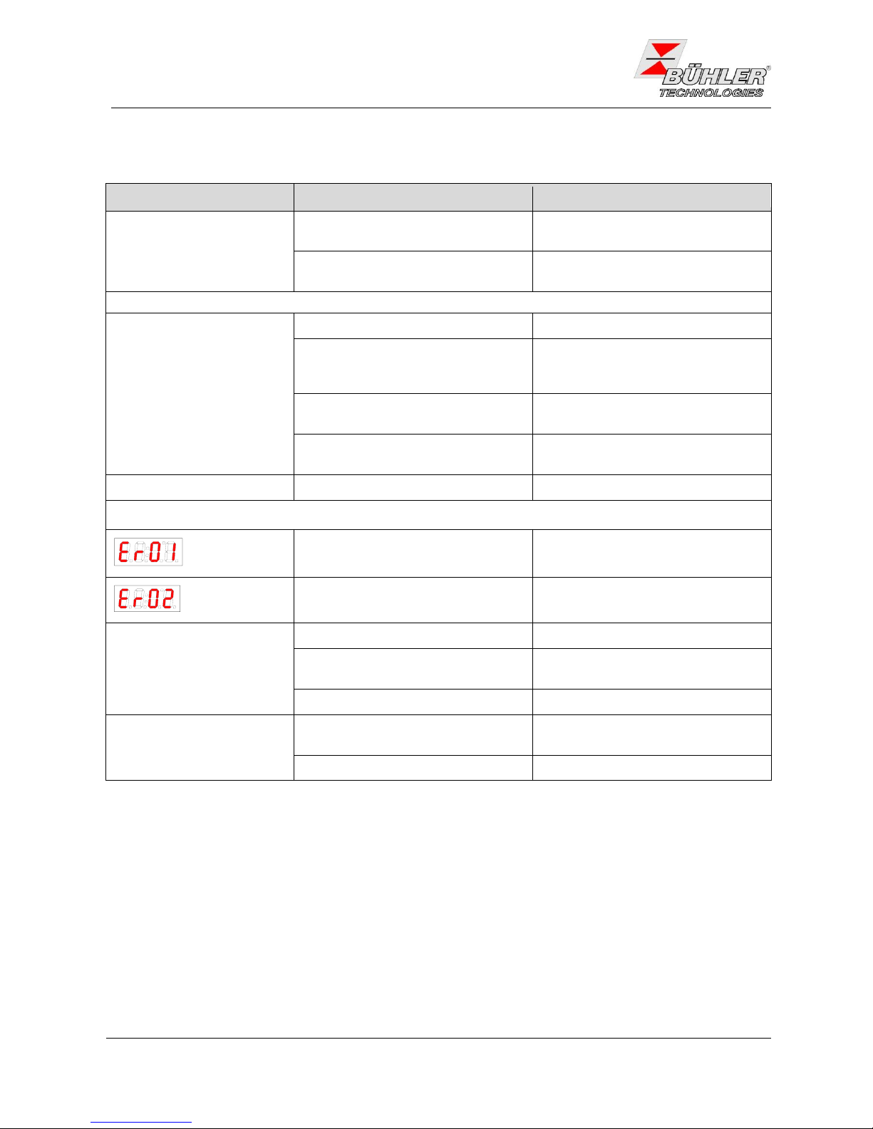
6.2 Troubleshooting
Problem / Failure
Possible cause
Solution
No display
- no power
- check power supply
- fuse blown
- Check fuse and change it if
necessary
Status-LED blinks with
- High Temperature
- operational temperature not yet
reached
- wait for 20 minutes maximum
- cooling capacity to low, even
though cooler is running
- make sure that air can circulate
free and that ventilation louvres
are not obstructed
- gas flow / dew point / gas temperature to high
- check application parameters,
install pre-separator
- fan broken
- check fan, replace if necessary
- Low temperature
- controller defect
- send cooler for inspection
Display of an error
Error 01
- broken wire
- Temperature sensor defect: send
cooler for repair
Error 02
- short circuit
- Temperature sensor defect: send
cooler for repair
Condensate in gas outlet
- condensate vessel full
- drain vessel
- valve in automatic condensate
drain is stuck
- flush both directions
- cooler overloaded
- check limiting parameters
Reduced gas flow
- clogged gas path
- check / flush heat exchanger
- condensate outlet clogged by ice
- send cooler for inspection
Page 31

Bedienungs- und Installationsanleitung
Installation- and Operation Instruction
Messgaskühler / Sample Gas Coolers PKE-5xx
BX440010 08/2013 Art. Nr. 90 31 105
31
6.3 Replacement of Micro-Fuse of the Cooler
6.3.1 115 V and 230 V
Disconnect the cooler from power supply.
Loosen the 8 screws fixing the cover to the case. If peristaltic
pumps are installed to the cooler they must be disassembled
because they are fixed with the cover-screws.
Remove the cover carefully. Caution: The display is fixed to the
cover and is connected to the electronics inside the device. The
plug can be put off to lay the cover down.
The fuse is placed on the small supply circuit board, covered by a
plastic cap. Replace the fuse and refit the cap. Regard the supply
voltage for choosing the correct fuse.
Reconnect the plug of the display and fix the cover. Fasten the
screws or install the pumps, respectively.
Reconnect power supply.
6.3.2 24 V DC
Disconnect the cooler from power supply.
Loosen the 8 screws fixing the cover to the case.
Remove the cover carefully. Caution: The display is fixed to the
cover and is connected to the electronics inside the device. The
plug can be put off to lay the cover down.
The fuse is placed in the fuse holder (see picture). Turn to open it
and replace the fuse. Regard the supply voltage for choosing the
correct fuse.
Reconnect the plug of the display and fix the cover. Fasten the
screws.
Reconnect power supply.
6.4 Cleaning of the heat exchanger
The heat exchanger must be replaced only in case of damage or when clogged. In the latter case we
recommend to check if the use of a filter will avoid such clogging in the future.
Turn off gas supply.
Disconnect the cooler from the mains.
Loosen gas fittings and condensate drain fitting. Collect condensate.
Pull out the heat exchanger upwards out of the cooler.
Clean the cooling nest (hole in cooling block).
Clean the heat exchanger until all impurities are disposed.
Grease the heat exchanger on the cooling surfaces with silicone grease.
Introduce the heat exchanger with turning movement into cooling nest.
Re-establish fittings for gas tubes and condensate drain.
Page 32

Bedienungs- und Installationsanleitung
Installation- and Operation Instruction
Messgaskühler / Sample Gas Coolers PKE-5xx
32
BX440010 08/2013 Art. Nr. 90 31 105
6.5 Replacing the Fuse of the peristaltic Pump
Disconnect the pump from the mains.
Remove the insulation cover from the fuse holder at the pump’s mounting bracket. For this, push the
cover using a screw driver and quarter-turn it to the left.
Replace the fuse and refit the insulation cover by quarter-turning it to the right.
Reconnect the cooler to the mains.
6.6 Replacement of the peristaltic pump’s hose (just in case pump
is fitted)
Turn off gas supply.
Switch the device off and disconnect power supply.
Disconnect input and output hoses (Take care of the safety instructions!)
Loosen but don’t remove the centre knurled thumb screw. Push screw downwards.
Remove cover
Push terminals side wards.
Replace hose and step backwards the above steps for mounting.
6.7 Spare parts
To order spare parts please indicate type of cooler and serial no. For accessories and enhancement see data
sheets and/or catalogue.
The following parts are recommended for stocking:
Spare part
Part no.
Replacement hose for peristaltic pump 0.3 l/h
(only if your cooler is equipped with pump)
91 240 30 027
Fuse cooler
230 V
5x20 mm, 1.25 A slow
91 100 00 058
115 V
5x20 mm, 2.5 A slow
91 100 00 013
24 V DC
5x20 mm, 6.3 A slow
91 100 00 063
Fuse peristaltic pump
230 V / 115 V
5x20 mm, 1 A fast-acting
91 100 00 061
Display ABT 400
91 000 10 124
Controller board MCP1
91 000 10 125
Controller board PKE
91 000 10 126
Mains board
91 000 10 127
6.8 Attached documents
- Data sheet PKE 5xx: DE 44 0012, DA 44 0012
- Declarations of conformity: KX 44 0002
- Declaration of Contamination status
Page 33

Gaskühler Baureihe PKE 5
Bei der Baureihe PKE 5 kühlen Peltierelemente den aus
Aluminium gefertigten Kühlblock. In diesen können je nach
Grundversion ein ode zwei hocheffiziente Wärmetauscher wahlweise aus Edelstahl, Duranglas ode PVDF -eingesteckt
werden. Konzipiert ist der PKE 5 in der Grundversion für
mäßige Umgebungstemperaturen und Gasleistungen mit
typischerweise 150 l/h bei 70 °C Gaseingangstemperatur
und etwa 40 °C Eingangstaupunkt (ca. 5 Vol%). Für höhere
Umgebungstemperaturen bis max. 50 °C stehen die
VersionenPKE 52xzur Verfügung.
Der auf 5 °C voreingestellte Ausgangstaupunkt wird durch
eine elektronische Regelungkonstant gehalten.
Die Temperatur des Kühlblockes wird durch eine programmierbare Anzeige dargestellt. Diese wird durch eine
blinkende Anzeige für Über- und Untertemperatur sowie
einen Relaisausgang in Fail-Safe-Schaltung ergänzt. Diese
Statusausgaben markieren einen einstellbaren Bereich um
den eingestellten Ausgangstaupunkt.
Für das abgeschiedene Kondensat bieten wir je nach
Betriebsart des Aufbereitungssystems automatische
Kondensatableiter oder peristaltischePumpen an.
§
§
§
§
§
§
§
§
§
Kompakte Abmessungen
Kurze Inbetriebnahmezeit
Wartungsfrei
Geringe Betriebsgeräusche
Version für hohe
Umgebungstemperaturen
Nennleistung 100/90 kJ/h
Taupunktstabilität 0,1 °C
Statusanzeige und -ausgang
Anzeige der Kühlblocktemperatur
DD 44 0012
10/2013
Seite 1/4
Bühler Technologies GmbH
D - 40880 Ratingen, Harkortstr. 29
Tel.: + 49 (0) 2102 / 49 89-0 Fax: + 49 (0) 2102 / 4989-20
Internet: www.buehler-technologies.com
e-mail: analyse@buehler-technologies.com
Page 34

Technische Daten für alle Typen
Betriebsbereitschaft nach max. 10 Minuten
Umgebungstemperatur 5 °C bis 40 °C / 50 °C
Gasausgangstemperatur,
voreingestellt 5 °C
Schutzart IP 20
Gehäuse Edelstahl
Verpackungsmaße ca. 350 x 220 x 220 mm
Gewicht incl. Wärmetauscher ca. 7,5 kg
bei 24 V DC ca. 6 kg
Spannungsversorgung 115 V AC, 230 V AC
oder 24 V DC, 50/60 Hz
Leistungsaufnahme max. 120 VA
Schaltleistung Statusausgang max. 230 V AC, 150 V DC
2A,50VA
Potentialfrei
Elektrische Anschlüsse,
Standardanwendungen
(PKE 511, 512, 521, 522) Stecker nach DIN 43650
DD 44 0012
Seite 2/4
10/2013
Typenübersicht
Die Baureihe PKE 5 besteht aus verschiedenen Typen, die nach zwei Kriterien geordnet werden können:
1) Die verfügbare Kühlleistung bzw. die maximale Umgebungstemperatur
2) Die Anzahl der Wärmetauscher
Diese Unterteilung findet sich in der Typenbezeichnung wieder. Die genaue Artikelnummer der von Ihnen definierten Type
ermittelt sich aus dem Typenschlüssel in der Rubrik Bestellhinweise.
Die allgemeinen Daten für alle Typen finden Sie unten auf dieser Seite.
Auf der nächsten Seite finden Sie die Kühlleistungskurven und speziellen Leistungsdaten für die einzelnen Kühler getrennt.
Weiter gibt es auch eine Übersicht über die Daten der einzelnen Wärmetauscher.
Beschreibung
Die Steuerung des Kühlers erfolgt durch einen
Mikroprozessor. Durch die Werksvoreinstellung sind die
unterschiedlichen Charakteristika der eingebauten
Wärmetauscher bereits vonder Steuerungberücksichtigt.
Es können mittels der 3 Tasten menügeführt applikationsindividuelle Einstellungen einfach getätigt werden. Dies
betrifft zum einen den Soll-Ausgangstaupunkt, der von 2
bis 20 °Ceingestellt werdenkann (werksseitig5 °C).
Ein Unter- bzw. Überschreiten des eingestellten
Warnbereiches (z. B. nach dem Einschalten) wird sowohl
durch Blinkender Anzeige als auchdurch das Statusrelais
signalisiert.
Der Statusausgang kann z.B. zum Steuern der
Messgaspumpe verwendet werden, um ein Zuschalten
des Gasstroms erst bei Erreichen des zulässigen Kühlbereiches zu ermöglichen.
Zum anderen können die Warnschwellen für die Unterbzw. Übertemperatur eingestellt werden. Diese werden
relativ zum eingestelltenAusgangstaupunkt gesetzt.
Für die Untertemperatur steht hier einBereich von -1..3K
(mindestens jedoch 1 °C) zur Verfügung, für die Übertemperatur ein Bereich von +1..7K. Die Werkseinstellungen für beideWerte sind 3K.
a
a
a
t
t
t
Anwendung
40 °C 50 °C
PKE 511 PKE 521
PKE 512 PKE 522
Standardanwendungen
Max. Umgebungstemperatur
1 Wärmetauscher
2 Wärmetauscher
2.Ziffer=1 2.Ziffer=2
3.Ziffer=1
3.Ziffer=2
Page 35

5 10152025303540°C50
0
20
40
60
80
120
5 10152025 3035 40°C50
0
20
40
60
80
120
5 1015202530
°C
35 40
kJ/h
kJ/h
0
20
40
50
80
120
5 10152025303540
°C
kJ/h
10
30
60
70
90
100
0
20
40
50
80
120
kJ/h
10
30
60
70
90
100
Ein Wärmetauscher
Typ PKE 511
Nennkühlleistung (bei 25 °C) 100 kJ/h
Max. Umgebungstemperatur 40 °C
Taupunktschwankungen statisch ± 0,1 K
im gesamten Spezifikationsbereich ± 1,5 K
Zwei Wärmetauscher
Typ PKE 512
Nennkühlleistung (bei 25 °C) 100 kJ/h
Max. Umgebungstemperatur: 40 °C
Taupunktschwankungen statisch: ± 0,1 K
im gesamten Spezifikationsbereich ± 1,5 K
Temperaturunterschied zwischen den
Wärmetauschern < 0,5 K
Typ PKE 521
Nennkühlleistung (bei 25 °C) 90 kJ/h
Max. Umgebungstemperatur: 50 °C
Taupunktschwankungen statisch: ± 0,1 K
im gesamten Spezifikationsbereich ± 1,5 K
Typ PKE 522
Nennkühlleistung (bei 25 °C) 90 kJ/h
Temperaturunterschied zwischen den
Wärmetauschern < 0,5 K
Max. Umgebungstemperatur 50 °C
Taupunktschwankungen statisch ± 0,1 K
im gesamten Spezifikationsbereich ± 1,5 K
DD 440012
Seite 3/4
10/2013
Wärmetauscher PTS PTG PTV MTS MTG MTV
PTS-I PTG PTV-I MTS-I MTG MTV-I
3) 3) 3)
2) 2) 2) 3) 3) 2) 3)
)
)
)
)
Durchfluss v 450 l/h 250 l/h 250 l/h 300 l/h 210 l/h 190 l/h
Eingangstaupunkt 65 °C 65 °C 65 °C 65 °C 65 °C 65 °C
Gaseingangstemp. 180 °C 140 °C 140 °C 140 °C 140 °C 140 °C
Max. Kühlleistung Q 150 kJ/h 90 kJ/h 90 kJ/h 95 kJ/h 80 kJ/h 65 kJ/h
Gasdruck p 160 bar 3 bar 2 bar 25 bar 3 bar 2 bar
Differenzdruck p (v=150 l/h) 10 mbar 10 mbar 10 mbar 20 mbar 19 mbar 18 mbar
Totvolumen V 29 ml 29 ml 57 ml 19 ml 18 ml 17 ml
Anschlüsse Gas (Metrisch) Swagelok 6 mm GL 14 (6 mm) DN 4/6 Rohr 6 mm GL14 (6 mm) DN 4/6
(Zöllig) 1/4” GL 14 (1/4”) 1/4”-1/8” Rohr 1/4” GL14 (1/4”) 1/4”-1/8”
Kondensatablass (metrisch) G 3/8” GL 25 (12 mm) G3/8" G1/4” GL18 (8 mm) G 1/4”
(Zöllig) NPT 3/8“ GL 25 (1/2”) NPT 3/8" NPT 1/4” GL18 (8 mm) NPT 1/4”
max
e,max
G,max
max
max
tot
1)
1)
1)
4
4
4
4
t
J
D
1)
2)
3)
Unter Berücksichtigung der maximalen Kühlleistung des Kühlers
Typen mit I sind mit NPT-Gewinden bzw. zölligen Rohren
Bei den Wärmetauschern MTS, MTG und MTV, ist eine Kondensatableitung mit automatischenAbleitern nicht möglich
Innendurchmesser Dichtring
4)
Anmerkung: Die Grenzkurven für die Wärmetauscher PTG, PTV bzw. MTV gelten bei einem Taupunkt von 40 °C.
Wärmetauscher
Die Energie des Messgases und damit in erster Näherung die abgeforderte Kühlleistung Q wird bestimmt durch die drei
Parameter Gastemperatur , Taupunkt (Feuchtigkeitsgehalt) und Volumenstrom v. Physikalisch bedingt steigt bei
wachsender Gasenergie der Ausgangstaupunkt. Nachfolgende Grenzen für denmaximalen Durchflusssind festgelegtfür einen
Normarbeitspunkt von =40 °Cund =70 °C. Angegeben wird der maximale Volumenstrom v in Nl/h gekühlter Luft, also nach
dem Auskondensieren des Wasserdampfes. Für andere Taupunkte und Gaseingangstemperaturen können die Werte
differieren. Die physikalischen Zusammenhänge sind jedoch so umfangreich, dass von einer Darstellung abgesehen wird. Bitte
nehmen Sie beiUnklarheiten unsere Beratung inAnspruch odernutzen Sie unserAuslegungsprogramm.
Jt
tJ
Ge
eG max
Umgebungstemperatur
PKE mit
2xMTS
PKE mit
2xMTS
Grenze für
2xMTV
Umgebungstemperatur
PKE mit
PTS
PKE mit
PTS
Grenze für
PTG, PTV
Grenze für
PTG, PTV
Umgebungstemperatur
Umgebungstemperatur
Kühlleistung
Kühlleistung
Kühlleistung
Kühlleistung
Grenze für
2xMTG
Grenze für
2xMTG
Grenze für
2xMTV
Page 36

44446
6
000
0
5
11
521
1
2
3
1
2
0
1
512
522
1
3
1
2
0
2
NETZ
POWER
ALARMAUSGANG
ALARMOUTPUT
ENTER
292
90
Ø7
114,5
105,5
98
112
165
165
153,5
310
140
150
130
A000138X
3
4
3
4
0
0
2
5
6
5
6
Abmessungen
Typen für Standardanwendungen (PKE 51x und 52x)
Zubehör
Artikel Nr. Beschreibung
451 000 8 Automatischer Kondensatabscheider AK 5.2
441 000 5 Glassammelgefäß GL 1
912 403 0027 Ersatzschlauch mit abgewinkelten Anschlüssenfür peristaltische Pumpen
DD 44 0012
Seite 4/4
10/2013
Technische Änderungen vorbehalten
Bestellhinweise
Die genaue Artikelnummer der von Ihnen definierten Type ermittelt sich aus dem nachfolgenden Typenschlüssel.
Jeder einzelne Gasweg ist mit einer peristaltischen Pumpe oder einem Kondensatableiter auszurüsten. Bei
24 V Netzspannung ist das werkseitige Ausrüsten einer peristaltischen Pumpe nicht möglich.
Bitte beachten:
Luft
Ein
Luft
Aus
Luft
Ein
Luft
Aus
Typen mit 1 Wärmetauscher
PKE 511: Standard Umgebungstemperatur 40 °C
PKE 521: Standard Umgebungstemperatur 50 °C
115 V Metrische Verschraubungen
Versorgungsspannung
230 V Metrische Verschraubungen
Edelstahl / (PTS oder PTS-I)
Glas / (PTG)
Material Wärmetauscher / Version
PVDF / (PTV oder PTV-I)
Kondensatpumpen
ohne
eine
Typen mit 2 Wärmetauschern
115 V Metrische Verschraubungen
Versorgungsspannung
230 V Metrische Verschraubungen
Edelstahl / (MTS oder MTS-I)
Material Wärmetauscher / Version
PVDF / (MTV oder MTV-I)
PKE 522: Standard Umgebungstemperatur 50 °C
Kondensatpumpen (nur 115 V / 230 V)
1)
PKE 512: Standard Umgebungstemperatur 40 °C
ohne
zwei
Art. Nr.
Art. Nr.
1)
Bei den Wärmetauschern MTS, MTG und MTV, ist eine Kondensatableitung mit automatischenAbleitern nicht möglich.
115 V Zöllige Verschraubungen
230 V Zöllige Verschraubungen
115 V Zöllige Verschraubungen
230 V Zöllige Verschraubungen
Glas / (MTG)
24 V DC Metrische Verschraubungen
24 V DC Zöllige Verschraubungen
24 V DC Metrische Verschraubungen
24 V DC Zöllige Verschraubungen
Page 37

Sample Gas Cooler PKE 5
The PKE Models feature a semiconductor Peltier cooling
system with an aluminum cooling block. Fitted into the block
are one or two removable high efficient heat exchanger
made of stainlesssteel, DURAN-glassor PVDF.
The dew pointof 5°C is regulated byan electronic controller.
The temperature (in °C or°F) of the coolingblock is shown on
a programmable LED-display. The status is indicated by a
flashing display which shows too high or low temperature
and operates togetherwith arelay infail-safe mode.
Condensate is removed by peristaltic pumps, automatic
condensate drains orcondensate vessels.
The PKE 5 is designed for moderate ambient and gas
temperatures (150 l/h @ 70°C) and an inlet dew point of
about 40 °C (appox. 5 Vol%). For higher ambient temperatures up toa maximumof 50 °C orderthe PKE 52x.
§
§
§
§
§
§
§
§
§
Compact design
Easy installation
No maintenance required
Low noise
Model available for high ambient
temperatures
Nominal cooling capacity 90/100 kJ/h
Dew point stability 0.1 °C
Status display and status output
Cooling temperature display
DE 44 0012
Page 1/4
10/2013
Bühler Technologies GmbH
D - 40880 Ratingen, Harkortstr. 29
Tel.: + 49 (0) 2102 / 49 89-0 Fax: + 49 (0) 2102 / 4989-20
Internet: www.buehler-technologies.com
e-mail: analyse@buehler-technologies.com
Page 38

Model Overview
The PKE 5 Peltier cooler family includes several types which may be categorised by two criteria:
1) Cooling capacity and maximum ambient temperature
2) Number of heat exchangers
These criteria can be specified in the model number as shown in the table below. Please extract the part number for the
cooler fulfilling your requirements from the type code on page 4.
The general specifications can be found in the table below. On the next page are the performance curves and the
specifications for each cooler. In the table below that there is an overview of the heat exchanger's data.
Description
The PKE coolers are controlled by a microprocessor. The
different operating characteristics of the heat exchangers
are established atthe factory.
Menu-guided with three keys it is easily possible to adapt
settings to thespecific requirementsof any application.
Warning limits for high or low temperature can be set
relative to the chosen outlet dew point . For low
temperature the range is 1..3°C (minimum 1°C / 34°F).
For high temperature it is +1..7°C. Factory preset for
both is 3°C.
The status contact could be usedto controlthe samplegas
pump so that the gas flow is turned on when the cooler
reaches the desiredtemperature.
The outlet dew point can be set in a range of 2 to 20 °C
(36..68°F). It isfactory presetto 5°C (41°F).
When the warninglimits are exceeded (e.g.at start-up) this
is signalised bya flashingdisplay andthe status contact.
t
t
t
a
a
a
Technical Specifications for All Models
Ready for application after max. 10 Minutes
Ambient temperature +5 to 40 °C/ 50 °C
Factory set dew point 5°C
Protection class IP 20
Material of housing stainless steel
Packing dimensions appr. 350 mm x 220 mm x 220 mm
Weight including heat
exchanger(s) appr. 7,5 kg
at 24 V DC appr. 6 kg
Power supply 115 V AC, 230 V AC
or 24 V DC, 50/60 Hz
Power consumption max. 120 VA
Status output max. 230 V AC, 150 V DC
2A,50VA,dry
Potential-free
Electrical connectors
Standard applications
(PKE 511, 512, 521, 522) plugs according to DIN 43650
DE 44 0012
Page 2/4
10/2013
Application:
40 °C 50 °C
Standard
Max. ambient temperature:
1 heat exchange
2 heat exchanger
PKE 511 PKE 521
PKE 512 PKE 522
3rd no. = 1
3rd no. = 2
2nd no. = 1
2nd no. = 2
Page 39

5 10152025303540°C50
0
20
40
60
80
120
5 10152025 3035 40°C50
0
20
40
60
80
120
5 1015202530
°C
35 40
kJ/h
kJ/h
0
20
40
50
80
120
5 10152025303540
°C
kJ/h
10
30
60
70
90
100
0
20
40
50
80
120
kJ/h
10
30
60
70
90
100
One heat exchanger
Type PKE 511
Nominal cooling capacity (at 25 °C) 100 kJ/h
Max. ambient temperature 40 °C
Drift over full range ± 1.5 K
Dew point noise static ± 0.1 K
Two heat exchangers
Type PKE 512
Nominal cooling capacity (at 25 °C) 100 kJ/h
Max. ambient temperature 40 °C
Dew point noise static ± 0.1 K
Drift over full range ± 1.5 K
Temperature differential between
heat exchangers < 0.5 K
Type PKE 521
Nominal cooling capacity (at 25 °C) 90 kJ/h
Max. Ambient temperature 50 °C
Dew point noise static ± 0.1 K
Drift over full range ± 1.5 K
Type PKE 522
Nominal cooling capacity (at 25 °C) 90 kJ/h
Max. Ambient temperature 50 °C
Dew point noise static ± 0.1 K
Drift over full range ± 1.5 K
Temperature differential between
heat exchangers < 0.5 K
Heat exchanger
The energy content of the sample gas and, as a result, the required cooling capacity of the cooling system is determined by 3
parameters: gas temperature , dewpoint (moisture content)and flow v.
The outletdew point raises with increasing energy content (heat) of the gas. The required cooling capacity is determined by the
mximum acceptable levelof theoutlet dewpoint.
The following table shows cooler performance assuming the following conditions: =40°C and =70°C. Indicated is the v in
Nl/h cooled air(i.e. afterthe moisture has condensed).With other dewpoints andgas inlet temperatures thevalues may differ.
Jt
tJ
Ge
e G max
Please contact one of Buhler’s application specialists for assistanceand further information.
Heat exchanger GPTS PTG PTV MTS MT MTV
PTS-I PTG PTV-I MTS-I MTG MTV-I
3) 3) 3)
2) 2) 2) 3) 3) 2) 3)
)
)
)
)
Flow rate v 450 l/h 250 l/h 250 l/h 300 l/h 210 l/h 190 l/h
Inlet dew point 65 °C 65 °C 65 °C 65 °C 65 °C 65 °C
Gas inlet temp. 180 °C 140 °C 140 °C 140 °C 140 °C 140 °C
Max. cooling capacity Q 150 kJ/h 90 kJ/h 90 kJ/h 95 kJ/h 80 kJ/h 65 kJ/h
Gas pressure p 160 bar 3 bar 2 bar 25 bar 3 bar 2 bar
Pressure drop p (v=150 l/h) 10 mbar 10 mbar 10 mbar 20 mbar 19 mbar 18 mbar
Dead volume 29 ml 29 ml 57 ml 19 ml 18 ml 17 ml
Swagelok 6 mm GL 14 DN 4/6 tube 6 mm GL14 (6 mm) DN 4/6
1/4” GL 14 (1/4”) 1/4”-1/8” tube 1/4” Gl14 (1/4”) 1/4”-1/8”
G 3/8“ GL 25 G3/8" G1/4” GL18 (8 mm) G 1/4”
NPT 3/8“ GL 25 (1/2”) NPT 3/8" NPT 1/4” GL18 (8 mm) NPT 1/4”
max
e,max
G,max
max
max
1)
1)
1)
4
4
4
4
1)
2)
3)
4)
t
J
D
Sample gas connections (metric) (6 mm)
(US)
Condensate out connection (metric) (12 mm)
(US)
Consider the maximum cooling capacity of cooler
Heat exchangers MTS, MTG and MTV cannot be drained by automatic drainers
Inner diameter gasket
Types marked “I” have NPT-threads or US tubes, respectively
Note: The limits in the diagrams for the PTG, PTV respectively MTV are for a dew point of 40°C.
DE 440012
Page 3/4
10/2013
limit for
2xMTV
PKE with
2xMTS
Ambient temperature
PKE with
PTS
limit for
PTG,PTV
Ambient temperature
PKE with
2xMTS
limit for
2xMTV
Ambient temperature
limit for
PTG,PTV
Ambient temperature
Cooling capacity
Cooling capacity
Cooling capacity
Cooling capacity
PKE with
PTS
limit for
2xMTG
limit for
2xMTG
Page 40

44446
6
000
0
5
11
521
1
2
3
1
2
0
1
512
522
1
3
1
2
0
2
NETZ
POWER
ALARMAUSGANG
ALARMOUTPUT
ENTER
292
90
Ø7
114,5
105,5
98
112
165
165
153,5
310
140
150
130
A000138X
3
4
3
4
0
0
2
5
6
5
6
Types with one Heat Exchanger
PKE 511: Standard ambient temperature 40 °C
PKE 521: Standard ambient temperature 50 °C
115 V metric fittings
Power Supply
230 V metric fittings
Stainless steel / (PTS or PTS-I)
Glass / (PTG)
Material Heat Exchanger / Version
PVDF / (PTV or PTV-I)
Condensate Discharge
None
One peristaltic pump
Types with two Heat Exchangers
115 V metric fittings
Power Supply
230 V metric fittings
Stainless steel / (MTS or MTS-I)
Material Heat Exchanger / Version
PVDF / (MTV or MTV-I)
PKE 522: Standard ambient temperature 50 °C
Condensate Discharge (only 115 V / 230 V)
1)
PKE 512: Standard ambient temperature 40 °C
None
Two peristaltic pumps
1)
Heat exchangers MTS, MTG and MTV cannot be drained by automatic drainers
DE 440012
Page 4/4
10/2013
Accessories
Part No. Description
45 100 08 Automatic condensate drain type AK 5.2
44 100 05 Glass vessel GL 1
91 240 300 27 Spare tube for peristaltic pump, right angle terminals
Please indicate with order
Please extract the part number for the cooler fulfilling your requirements from the type code below.
: Each gas path should be equipped with a peristaltic pump or an automatic condensate drain. A peristaltic
pump cannot be installed at the factory in versions with 24 V mains supply.
Please note
We reserve the right to amend specification
Dimensions (mm)
Models for standard applications (PKE 51x und 52x)
Air
In
Air
Out
Air
In
Air
Out
115 V US fittings
115 V US fittings
230 V US fittings
230 V US fittings
Glass / (MTG)
Part-no.
Part-no.
24 V DC metric fittings
24 V DC US fittings
24 V DC metric fittings
24 V DC US fittings
Page 41

Sample Gas Cooler PKE 5
Accurate measurement of gases requires gas samples with
stable dew pointseven underharsh ambientconditions.
The PKE 5 is designed for moderate ambient and gas
temperatures (2.5 lpm at @ 158 °F) and an inlet dew point of
about 104 °F (approx. 5% vol). For higher ambient temperatures up toa maximumof 122 °F orderthe PKE 52x.
The dew point of 41 °F is regulated by an electronic controller. The temperature (in °F or °C) of the cooling block is
shown on an LED-display. The status is indicated by a
flashing display which shows high or low temperature and
operates together witha relayin fail-safemode.
Condensate is removed by peristaltic pumps, automatic
condensate drains orcondensate vessels.
The PKE Models feature a semiconductor Peltier cooling
system with an aluminum cooling block. Fitted into the block
is a removable high-efficiency heat exchanger made of
stainless steel, DURAN-glassor PVDF.
§
§
§
§
§
§
§
§
§
§
Compact design
Easy installation
No maintenance required
Low noise
Efficient heat exchangers made of
stainless steel, Duran glass or PVDF
Nominal cooling capacity 85/95 Btu/hr
Dew point stability 0.2 °F
Status display and output
Cooling temperature display
Model available for high ambient
temperatures
DA 44 0012
Page 1/4
10/2013
Buhler Technologies LLC
1030 West Hamlin Road, Rochester Hills, MI 48309
Phone: 248.652.1546 Fax: 248.652.1598
Internet: www.buhlertech.com
e-mail: sales@buhlertech.com
Page 42

Model Overview
The PKE 5 Peltier cooler family includes several models which may be distinguished by two criteria:
1) Cooling capacity and maximum ambient temperature
2) Number of heat exchangers
These criteria can be specified in the model number as shown in the table below. Please extract the part
number for the cooler fulfilling your requirements from the type code on page 4.
Application:
122 °F
PKE 511 PKE 521
PKE 512 PKE 522
Standard
Max. ambient temperature:
1 heat exchanger
2 heat exchanger
104 °F
2nd no.=1
2nd no.=2
3rd no.=1
3rd no.=2
The general specifications can be found in the table below. On the next page are the
performance curves and the specifications for each cooler.
Description
Technical Specifications for All Models
The PKE coolers are controlled by a microprocessor.
The different operating characteristics of the heat
exchangers are establishedat thefactory.
Menu-guided with three keys it is easily possible to
adapt settings to the specific requirements of any
application.
The outlet dew point can be set within a range of
36 - 68°F. It isfactory preset to 41°F.
When the warning limits are exceeded (e.g. at startup), this is indicated by a flashing display and at the
status contact.
The statuscontact could be used to control the sample
gas pump so that the gas flow is turned on when the
cooler reaches thedesired temperature.
Warning limits for high or low temperature can be set
relative to the chosen outlet dew point . For low
temperature the range is 2 - 5 °F (minimum 34°F).
For high temperature it is 2 - 13 °F. Factory preset for
both is 5°F.
t
t
t
a
a
a
Ready for application after max. 10 Minutes
Ambient temperature 41 - 104 °F/ 122 °F
Factory set dew point 41 °F
Protection class IP 20
Material of housing Stainless steel
Packing dimensions appr. 13.8” x 8.7” x 8.7”
Weight including heat exch.(s) approx. 17 lb
at 24 V DC approx. 13 lb
Power supply 115 V AC, 230 V AC
or 24 V DC, 50/60 Hz
Power consumption max. 120 VA
Status output max. 230 V AC, 150 V DC
2A, 50 VA, dry
Potential-free
Electrical connectors
Standard applications
(PKE 511, 512, 521, 522) Plugs: DIN 43650
DA 44 0012
Page 2/4
10/2013
Page 43

0
20
40
60
80
100
120
40 50 60 70 80 90 100
Ambient temperature in °F
Cooling cap. in bt u/h
PK E
fitted
with
PTS
Limit for
PTG
and
PTV
0
20
40
60
80
100
120
40 50 60 70 80 90 100 110120
Ambient temperature in °F
Cooling cap. in bt u/h
PK E
fitted
with
PTS
Limit
PTG
and
PTV
0
20
40
60
80
100
120
40 50 60 70 80 90 100
Ambient temperature in °F
Cooling cap. in bt u/h
PK E
fitted
with
2xMTS
Limit for
2xMTV
0
20
40
60
80
100
120
40 50 60 70 80 90 100 110120
Ambient temperature in °F
Cooling cap. in bt u/h
PK E
fitted
with
2xMTS
Limit for
2xMTV
Limit for
2xMTG
Limit for
2xMTG
One heat exchanger
Model PKE 511
Nominal cooling capacity (at 77 °F) 95 Btu/hr
Max. ambient temperature 104 °F
Drift over full range ± 2.7 °F
Dew point noise static ± 0.18 °F
Two heat exchangers
Model PKE 512
Nominal cooling capacity (at 77 °F) 95 Btu/hr
Max. ambient temperature 104 °F
Dew point noise static ± 0.18 °F
Drift over full range ± 2.7 °F
Temperature differential between
heat exchangers < 0.9 °F
Model PKE 521
Nominal cooling capacity (at 77 °F) 85 Btu/hr
Max. ambient temperature 122 °F
Dew point noise static ± 0.18 °F
Drift over full range ± 2.7 °F
Model PKE 522
Nominal cooling capacity (at 77 °F) 85 Btu/hr
Max. Ambient temperature 122 °F
Dew point noise static ± 0.18 °F
Drift over full range ± 2.7 °F
Temperature differential between
heat exchangers < 0.9 °F
Note
: The limits in the diagrams for the PTG, PTV respectively MTV are for a dew point of 104 °F.
Heat Exchanger
The energy content of the sample gas and, as a result, the required cooling capacity of the gas cooler is determined by 3
parameters: gas temperature , dewpoint (moisture content) and flow v. The outlet dew point rises with increasing energy
content (heat) ofthe gas.The requiredcooling capacityis determinedby the maximumacceptable levelof theoutlet dew point.
The following tableshows cooler performance assumingthe following conditions: =120 °Fand =160 °F. Indicatedis the v in
lpm cooled air(i.e. afterthe moisture has condensed).With other dewpoints andgas inlet temperatures thevalues may differ.
Jt
tJ
Ge
e G max
Please contact one of Buhler’s application specialists for assistanceand further information.
Heat exchanger GPTS PTG PTV MTS MT MTV
PTS-I PTG PTV-I MTS-I MTG MTV-I
3) 3) 3)
2) 2) 2) 3) 3) 2) 3)
)
)
)
)
Flow rate v 7.5 lpm 4.2 lpm 4.2 lpm 5 lpm 3.5 lpm 3.2 lpm
Inlet dew point 150 °F 150 °F 150 °F 150 °F 150 °F 150 °F
Gas inlet temp. 356 °F 284 °F 284 °F 284 °F 284 °F 284 °F
Max. cooling capacity Q 142 Btu/hr 85 Btu/hr 85 Btu/hr 90 Btu/hr 76 Btu/hr 62 Btu/hr
Gas pressure p 2320 psi 43 psi 29 psi 363 psi 43 psi 29 psi
Pressure drop p (v=2.5 lpm) 0.15 psi 0.15 psi 0.15 psi 0.29 psi 0.28 psi 0.26 psi
Dead volume 1.8 cu. in. 1.8 cu. in. 3.5 cu. in. 1.2 cu. in. 1.1 cu. In. 1.0 cu. in.
Swagelok GL 14 (0.2 in.) DN 4/6 tube 0.2 in. GL14 (0.2 in.) DN 4/6
1/4” GL 14 (1/4”) 1/4”-1/8” tube 1/4” GL14 (1/4”) 1/4”-1/8”
G 3/8“ GL 25 (0.5 in.) G 3/8" G 1/4” GL18 (0.3 in.) G 1/4”
NPT 3/8“ GL 25 (1/2”) NPT 3/8" NPT 1/4” Gl18 (0.3 in.) NPT 1/4”
max
e,max
G,max
max
max
1)
1)
1)
4
4
4
4
1)
2)
3)
4)
t
J
D
Sample gas connections (metric) 0.2 in.
(US)
Condensate outlet connection (metric)
(US)
Consider the maximum cooling capacity of cooler
Types marked “I” have NPT-threads or US tubes, respectively
Heat exchangers MTS, MTG and MTV cannot be automatically drained
Inner diameter gasket
DA 440012
Page 3/4
10/2013
Page 44

NETZ
POWER
ALARMAUSGANG
ALARMOUTPUT
11.5”
3.54”
Ø0.28
4.51”
4.15”
3.86”
4.41”
6.5”
6.5”
6.04”
12.2”
5.51”
5.91”
5.12”
A000138A
ENTER
44446
6
000
0
5
11
521
1
2
3
1
2
0
1
512
522
1
3
1
2
0
2
3
4
3
4
0
0
2
5
6
5
6
Types with one Heat Exchanger
PKE 511: Standard ambient temperature 40 °C
PKE 521: Standard ambient temperature 50 °C
115 V metric fittings
Power Supply
230 V metric fittings
Stainless steel / (PTS or PTS-I)
Glass / (PTG)
Material Heat Exchanger / Version
PVDF / (PTV or PTV-I)
Condensate Discharge
None
One peristaltic pump
Types with two Heat Exchangers
115 V metric fittings
Power Supply
230 V metric fittings
Stainless steel / (MTS or MTS-I)
Material Heat Exchanger / Version
PVDF / (MTV or MTV-I)
PKE 522: Standard ambient temperature 50 °C
Condensate Discharge (only 115 V / 230 V)
1)
PKE 512: Standard ambient temperature 40 °C
None
Two peristaltic pumps
1)
Heat exchangers MTS, MTG and MTV cannot be drained by automatic drainers
Accessories
Part No. Description
45 100 08 Automatic condensate drain type AK 5.2
44 100 05 Glass vessel GL 1
91 240 300 27 Spare tube for peristaltic pump, right angle terminals
Please indicate with order
Please extract the part number for the cooler fulfilling your requirements from the type code below.
: Each gas path should be equipped with a peristaltic pump or an automatic condensate drain. A peristaltic
pump cannot be installed at the factory in versions with 24 V mains supply.
Please note
We reserve the right to amend specification
Dimensions (mm)
Models for standard applications (PKE 51x und 52x)
Air
In
Air
Out
Air
In
Air
Out
DA 440012
Page 4/4
10/2013
115 V US fittings
230 V US fittings
115 V US fittings
230 V US fittings
Glass / (MTG)
Part-no.
Part-no.
24 V DC metric fittings
24 V DC US fittings
24 V DC metric fittings
24 V DC US fittings
Page 45

Page 46

Dekontaminierungserklärung
Declaration of Contamination status
Gültig ab / valid since: 2011/05/01 Revision 0 ersetzt Rev. / replaces Rev ---
Bühler Technologies GmbH
D - 40880 Ratingen, Harkortstr. 29
Tel.: + 49 (0) 2102 / 4989-0 Fax: + 49 (0) 2102 / 4989-20
e-mail: service@buehler-technologies.com
Internet: www.buehler-technologies.com
Die gesetzlichen Vorschriften schreiben vor, dass Sie uns die Dekontaminierungserklärung ausgefüllt und unterschrieben
zurück zu senden haben. Die Angaben dienen zum Schutz unserer Mitarbeiter. Bringen Sie die Bescheinigung an der
Verpackung an. Ansonsten ist eine Bearbeitung Ihres Reparaturauftrages nicht möglich!
Legal regulations prescribe that you have to fill in and sign the Declaration of Contamination status and send it back. This
information is used to protect our employees. Please attach the declaration to the packing. Otherwise, your repair
order cannot be processed.
Gerät /
Device:
Serien-Nr. /
Serial no. :
Rücksendegrund /
Reason for return:
[ ] Ich bestätige hiermit, dass das oben spezifizierte Gerät ordnungsgemäß gereinigt und dekontaminiert wurde
und keinerlei Gefahren im Umgang mit dem Produkt bestehen.
I herewith declare that the device as specified above has been properly cleaned and decontaminated and that
there are no risks present when dealing with the device.
Ansonsten ist die mögliche Gefährdung genauer zu beschreiben / In other cases, please describe the hazards in
detail:
Aggregatzustand (bitte ankreuzen) / Condition of aggregation (please check):
Flüssig / Liquid Fest / Solid Pulvrig / Powdery Gasförmig / Gaseous
Folgende Warnhinweise sind zu beachten (bitte ankreuzen) / The following safety advices must be obeyed (please
check):
Explosiv
Explosives
Giftig / Tödlich
Acute toxicity
Entzündliche Stoffe
Flammable
Brandfördernd
Oxidizing
Komprimierte Gase
Gas under pressure
Gesundheitsgefährdend
Irritant toxicity
Gesundheitsschädlich
Health hazard
Umweltgefährdend
Environmental hazard
Bitte legen Sie ein aktuelles Datenblatt des Gefahrenstoffes bei / Please include the current material safety data sheet
of the hazardous material!
Angaben zum Absender / Information about the dispatcher:
Firma / Company: Anschrift / Address:
Ansprechpartner /
Contact person:
Abteilung / Division: E-Mail:
Tel. / Phone: Fax:
Ort, Datum /
Location, date:
Unterschrift /
Stempel
Signature / Stamp:
 Loading...