

Page 1

Bedienungs- und Installationsanleitung
Installation- and Operation Instruction
Meßgaskühler / Sample Gas Coolers PKE-42
Lesen Sie die Bedienungsanleitung vor Installation und/oder dem Gebrauch des Gerätes
gründlich durch, insbesondere die Hinweise unter Gliederungspunkt 2. Andernfalls können
Gesundheits- oder Sachschäden auftreten.
Die Bühler Technologies GmbH haftet nicht bei eigenmächtigen Änderungen am Gerät oder
unsachgemäßem Gebrauch.
Read this instruction carefully prior to installation and/or use. Pay attention particularly to all
advises and safety instructions to prevent injuries.
Bühler Technologies GmbH can not be held responsible for misusing the product or malfunction due to unauthorised modifications.
BX440009, 10/2008 Art. Nr. 90 31 100
Bühler Technologies GmbH, Harkortstr. 29, 40880 Ratingen, Deutschland
Tel. +49 2102 49 89-0, Fax. +49 2102 49 89-20
Internet: www.buehler-technologies.com
Email: analyse@buehler-technologies.com 1
Page 2

Bedienungs- und Installationsanleitung
Installation- and Operation Instruction
Meßgaskühler / Sample Gas Coolers PKE-42
2
BX440009, 10/2008 Art. Nr. 90 31 100
Inhaltsverzeichnis Seite
1 Einleitung........................................................................................................................................ 3
2 Wichtige Hinweise .........................................................................................................................3
2.1 Allgemeine Gefahrenhinweise............................................................................................... 4
3 Aufbauen und Anschließen .......................................................................................................... 5
3.1 Montage................................................................................................................................. 5
3.2 Elektrische Anschlüsse..........................................................................................................5
4 Betrieb und Wartung ..................................................................................................................... 6
4.1 Warnhinweise........................................................................................................................ 6
4.2 Betrieb ...................................................................................................................................7
4.3 Wartung................................................................................................................................. 7
5 Instandsetzung, Entsorgung ........................................................................................................ 7
5.1 Fehlerbehebung..................................................................................................................... 7
5.2 Entsorgen ..............................................................................................................................7
6 Anhang............................................................................................................................................ 8
6.1 Fehlersuche und Beseitigung................................................................................................ 8
6.2 Auswechseln der Feinsicherung ........................................................................................... 8
6.3 Austausch des Schlauches der peristaltischen Pumpe (wenn Pumpe vorhanden).............. 8
6.4 Demontage und Reinigung des Wärmeaustauschers........................................................... 9
6.5 Ersatzteile und Zusatzteile ....................................................................................................9
6.6 Beiliegende Unterlagen......................................................................................................... 9
Contents Page
1 Introduction.................................................................................................................................. 10
2 Important Advice.......................................................................................................................... 10
2.1 General indication of risk..................................................................................................... 11
3 Installation and Connection........................................................................................................ 12
3.1 Mounting..............................................................................................................................12
3.2 Electrical connection............................................................................................................ 12
4 Operation and Maintenance........................................................................................................ 13
4.1 Indication of risk................................................................................................................... 13
4.2 Operation............................................................................................................................. 14
4.3 Maintenance........................................................................................................................ 14
5 Repair and Disposal ....................................................................................................................14
5.1 Repair .................................................................................................................................. 14
5.2 Disposal...............................................................................................................................14
6 Appendices................................................................................................................................... 15
6.1 Trouble shooting.................................................................................................................. 15
6.2 Replacing the electrical fuse................................................................................................ 15
6.3 Replacement of the peristaltic pump’s hose (just in case pump is fitted) ........................... 15
6.4 Cleaning of the heat exchanger........................................................................................... 16
6.5 Spare parts.......................................................................................................................... 16
6.6 Attached documents............................................................................................................ 16
Page 3
Bedienungs- und Installationsanleitung
Installation- and Operation Instruction
Meßgaskühler / Sample Gas Coolers PKE-42
1 Einleitung
Der Messgaskühler PKE-42 Kühler ist zum Einsatz in Gasanalysensystemen bestimmt. Beachten Sie die Angaben der Datenblätter hinsichtlich spezifischen Verwendungszwecks, vorhandener Werkstoffkombinationen
sowie Druck- und Temperaturgrenzen.
2 Wichtige Hinweise
Der Einsatz der Geräte ist nur zulässig, wenn:
− das Produkt unter den in der Bedienungs- und Installationsanleitung beschriebenen Bedingungen, dem
Einsatz gemäß Typenschild und für Anwendungen, für die es vorgesehen ist, verwendet wird.
− die im Datenblatt und der Anleitung angegebenen Grenzwerte eingehalten werden.
− Überwachungsvorrichtungen/ Schutzvorrichtung korrekt angeschlossen sind.
− die Service- und Reparaturarbeiten von Bühler Technologies GmbH durchgeführt werden.
− Originalersatzteile verwendet werden.
Diese Bedienungsanleitung ist Teil des Betriebsmittels. Der Hersteller behält sich das Recht vor, die
Leistungs-, die Spezifikations- oder die Auslegungsdaten ohne Vorankündigung zu ändern. Bewahren Sie die
Anleitung für den späteren Gebrauch auf.
Begriffsbestimmungen für Warnhinweise:
HINWEIS
Signalwort für wichtige Information zum Produkt auf die im besonderen Maße aufmerksam
gemacht werden soll.
VORSICHT
Signalwort zur Kennzeichnung einer Gefährdung mit geringem Risiko, die zu einem Sachschaden oder leichten bis mittelschweren Körperverletzungen führen kann, wenn sie nicht
vermieden wird.
WARNUNG
Signalwort zur Kennzeichnung einer Gefährdung mit mittlerem Risiko, die möglicherweise
Tod oder schwere Körperverletzungen zur Folge hat, wenn sie nicht vermieden wird.
GEFAHR
Signalwort zur Kennzeichnung einer Gefährdung mit hohem Risiko, die unmittelbar Tod
oder schwere Körperverletzung zur Folge hat, wenn sie nicht vermieden wird.
Warnung vor einer allgemeinen Gefahr
Warnung vor explosionsgefährdeten Bereichen
Netzstecker
ziehen
Warnung vor elektrischer
Spannung
Warnung vor heißer Oberfläche
Atemschutz tragen
Warnung vor dem Einatmen giftiger Gase
Gesichtsschutz
tragen
Warnung vor ätzenden
Flüssigkeiten
Handschuhe
tragen
BX440009, 10/2008 Art. Nr. 90 31 100
3
Page 4
Bedienungs- und Installationsanleitung
Installation- and Operation Instruction
Meßgaskühler / Sample Gas Coolers PKE-42
2.1 Allgemeine Gefahrenhinweise
Beachten Sie unbedingt die für den Einbauort relevanten Sicherheitsvorschriften und allgemein gültigen Regeln der Technik. Beugen Sie Störungen vor und vermeiden Sie dadurch Personen- und Sachschäden.
Der für die Anlage Verantwortliche muss sicherstellen dass:
− Sicherheitshinweise und Betriebsanleitungen verfügbar sind und eingehalten werden.
− Unfallverhütungsvorschriften der Berufsgenossenschaften beachtet werden:
− Allgemeine Vorschriften” (VBG 1) und “Elektrische Anlagen und Betriebsmittel (VBG 4)”.
− Auf die Einhaltung der zulässigen Daten und Einsatzbedingungen achten.
− Schutzeinrichtungen verwendet werden und vorgeschriebene Wartungsarbeiten durchgeführt werden.
− Bei der Entsorgung bitte die gesetzlichen Regelungen beachtet werden.
Wartung, Reparatur
− Reparaturen an den Betriebsmitteln dürfen nur von Bühler autorisiertem Personal ausgeführt werden.
− Nur Umbau-, Wartungs- oder Montagearbeiten ausführen, die in dieser Bedienungs- und Installationsan-
leitung beschrieben sind
− Nur Original-Ersatzteile verwenden.
Bei
Durchführung von Wartungsarbeiten jeglicher Art müssen die relevanten Sicherheits- und Betriebsbe-
stimmungen beachtet werden
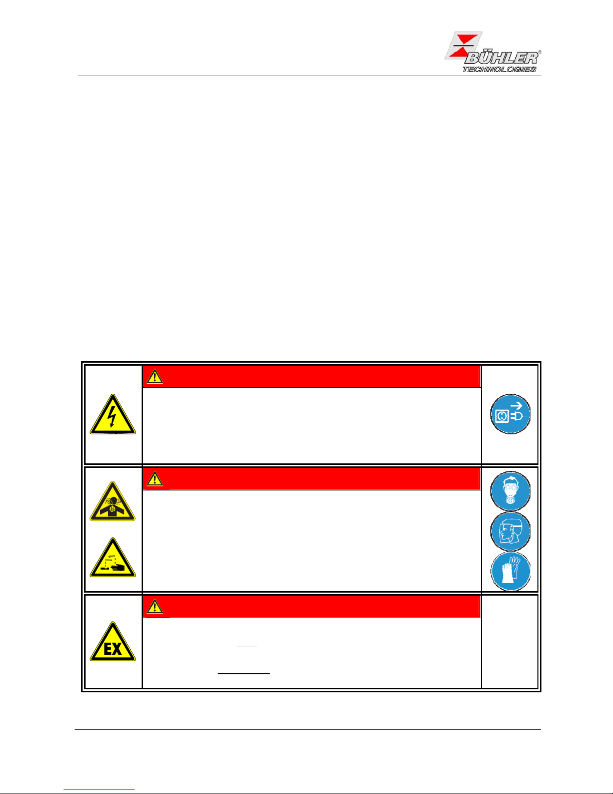
GEFAHR
Elektrische Spannung
Gefahr eines elektrischen Schlages.
Trennen Sie das Gerät bei allen Arbeiten vom Netz. Sichern Sie das Gerät
gegen unbeabsichtigtes Wiedereinschalten.
Das Gerät darf nur von instruiertem, fachkundigem Personal geöffnet werden.
GEFAHR
Giftige, ätzende Gase
Messgas kann gesundheitsgefährdend sein.
Bitte sorgen Sie ggf. für eine sichere Ableitung des Gases.
Schützen Sie sich bei der Wartung vor giftigen / ätzenden Gasen. Tragen Sie
die entsprechende Schutzausrüstung.
GEFAHR
Explosionsgefahr bei Verwendung in Explosionsgefährdeten Bereichen
Das Betriebsmittel ist
nicht für den Einsatz in explosionsgefährdeten Bereichen
geeignet.
Durch das Gerät
dürfen keine zündfähigen oder explosiven Gasgemische
geleitet werden.
4
BX440009, 10/2008 Art. Nr. 90 31 100
Page 5
Bedienungs- und Installationsanleitung
Installation- and Operation Instruction
Meßgaskühler / Sample Gas Coolers PKE-42
3 Aufbauen und Anschließen
Das Gerät ist für den Einsatz in geschlossenen Räumen vorgesehen. Beim Einsatz im Freien ist ein ausreichender Wetterschutz vorzusehen.
Der Messgaskühler ist an die Wand zu montieren. Unterhalb des Gerätes muß genügend Raum zur Ableitung
des Kondensates vorhanden sein. Oberhalb ist etwas Platz für die Gaszuführung vorzusehen.
Es ist darauf zu achten, daß die zulässige Umgebungstemperatur von +5 bis +50°C bei der PKE-42 eingehalten wird. Die Konvektion des Kühlers darf nicht behindert werden. An den seitlichen Lüftungsöffnungen muß
ausreichend Platz zum nächsten Hindernis sein. Insbesondere auf der Luftauslassseite (rechts) muss die
Entfernung mindestens 10 cm betragen. Bei Montage in geschlossenen Gehäusen, z.B. Analysenschränken,
ist für eine ausreichende Entlüftung zu sorgen. Reicht die Konvektion nicht aus, empfehlen wir, den Schrank
mit Luft zu spülen oder einen Ventilator vorzusehen, um die Innentemperatur zu senken.
3.1 Montage
Die Gaszuführung ist zum Kühler mit Gefälle zu verlegen. Bei großem Kondensatanfall empfehlen wir, eine
Kondensatvorabscheidung vor dem Kühler einzusetzen. Hierzu eignen sich unsere Flüssigkeitsabscheider mit
automatischer Kondensatentleerung 11 LD spez., AK 20 oder Typ 165.
Die Gaseingänge sind rot markiert. Gehen Sie beim Anschluß der Glaswärmetauscher vorsichtig vor und ziehen Sie die Verschraubungen nur von Hand an.
Bei Verwendung von automatischen Kondensatableitern muß die Gaspumpe vor dem Kühler montiert werden,
da sonst die Funktion der Kondensatableiter nicht mehr gewährleistet ist.
Hinweis: Der Wärmetauscher DTV kann nicht in Verbindung mit einem automatischen Kondensatableiter
betrieben werden.
Befindet sich die Messgaspumpe am Ausgang des Kühlers (Saugbetrieb), ist der Einsatz von Kondensatsammelgefäßen aus Glas oder der Einsatz von peristaltischen Pumpen zu empfehlen.
Für die Kondensatableitung stehen Glasgefäße und automatische Kondensatableiter zur Verfügung, die extern unterhalb des Gerätes zu montieren sind.
Anschluß der Kondensatableiter: je nach Werkstoff eine Verbindungsleitung aus Verschraubung und Rohr
oder Schlauch zwischen Wärmetauscher und Kondensatableiter herstellen. Bei Edelstahl kann der Kondensatableiter direkt am Verbindungsrohr aufgehängt werden, bei Schlauchleitungen ist der Kondensatableiter
mittels einer Schelle separat zu befestigen.
Kondensatleitungen sind grundsätzlich mit Gefälle und Mindestnennweite DN 8/10 zu verlegen.
Bei Verwendung einer peristaltischen Pumpe kann diese auch etwas entfernt vom Kühler befestigt werden.
3.2 Elektrische Anschlüsse
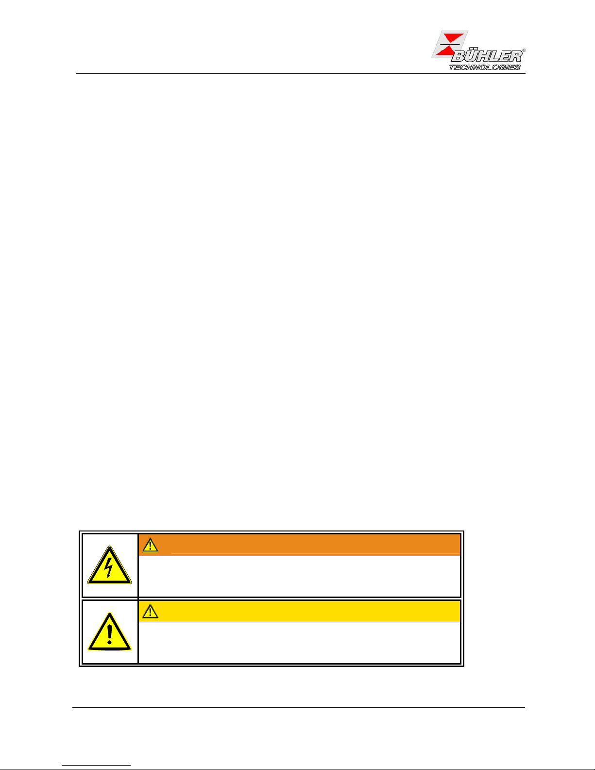
WARNUNG
Der Anschluss darf nur von geschultem Fachpersonal vorgenommen werden.
VORSICHT
Falsche Netzspannung kann das Gerät zerstören
Bei Anschluss auf die richtige Netzspannung gemäß Typenschild achten
BX440009, 10/2008 Art. Nr. 90 31 100
5
Page 6
Bedienungs- und Installationsanleitung
Installation- and Operation Instruction
Meßgaskühler / Sample Gas Coolers PKE-42
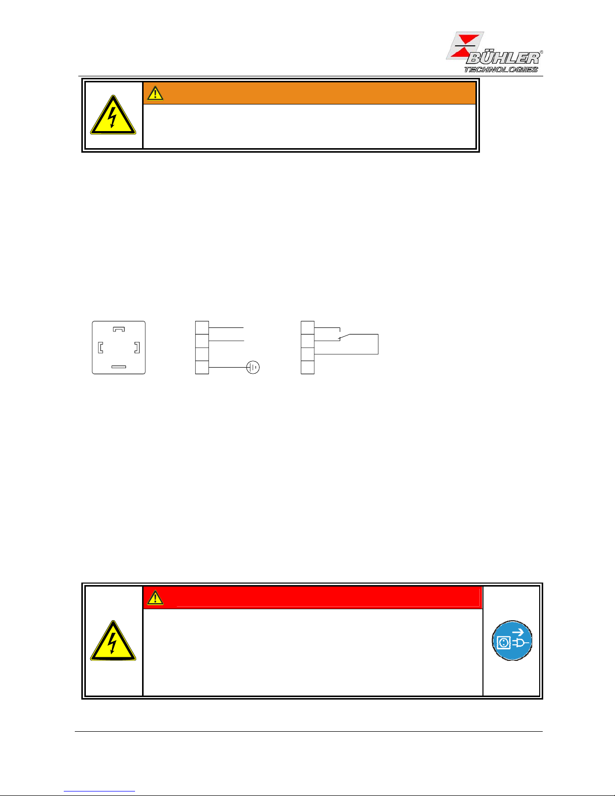
WARNUNG
Beschädigung des Gerätes bei Durchführung der Isolationsprüfung
Führen Sie keine Prüfung der Spannungsfestigkeit mit Hochspannung
am Gesamtgerät durch!
Das Gerät ist mit umfangreichen EMV-Schutzmaßnahmen ausgerüstet. Bei einer Prüfung der Spannungsfestigkeit werden elektronische Filterbauteile beschädigt. Die notwendigen Prüfungen wurden bei allen zu
prüfenden Baugruppen werkseitig durchgeführt (Prüfspannung je nach Bauteil 1 kV bzw. 1,5 kV).
Der Messgaskühler PKE-42 ist mit Steckern nach DIN 43650 ausgestattet. Diese sind bei korrektem Anschluss der Leitung verwechslungssicher angebracht. Bitte achten Sie deshalb darauf, dass die Stecker nach
dem Anschluss der Leitungen wieder entsprechend zusammengebaut werden. Nachfolgend sind die Anschlussbelegungen angegeben. Die angegebenen Nummern entsprechen denen auf den Steckern.
Die Speisespannung beträgt 230 VAC 50/60 Hz oder 115 VAC 50/60 Hz (Typenschild beachten).
Ist der Kühler mit peristaltischen Pumpen ausgerüstet, müssen diese separat an eine Spannungsquelle ange-
schlossen werden.
Steckernummerierung
1
1
1
L1
N
2
2
2
3
3
3
P
E
PE
PE
Funktion i.O.
Alarm
Netzanschluß
A
larmkontakt
4 Betrieb und Wartung
Der Gaskühler darf nicht außerhalb seiner Spezifikationen betrieben werden.
4.1 Warnhinweise
− Reparaturen an den Betriebsmitteln dürfen nur von Bühler autorisiertem Personal ausgeführt werden.
− Führen Sie nur Umbau-, Wartungs- oder Montagearbeiten aus, die in dieser Bedienungs- und Installati-
onsanleitung beschrieben sind.
− Verwenden Sie nur Original-Ersatzteile.
− Beachten Sie bei der Durchführung von Wartungsarbeiten jeglicher Art die relevanten Sicherheits- und
Betriebsbestimmungen.
GEFAHR
Elektrische Spannung
Gefahr eines elektrischen Schlages.
Trennen Sie das Gerät bei allen Arbeiten vom Netz. Sichern Sie das Gerät
gegen unbeabsichtigtes Wiedereinschalten.
Der Anschluss darf nur von geschultem Fachpersonal vorgenommen werden.
Achten Sie auf die korrekte Spannungsversorgung!
6
BX440009, 10/2008 Art. Nr. 90 31 100
Page 7
Bedienungs- und Installationsanleitung
Installation- and Operation Instruction
Meßgaskühler / Sample Gas Coolers PKE-42
GEFAHR
Giftige, ätzende Gase
Messgas kann gesundheitsgefährdend sein.
Bitte sorgen Sie ggf. für eine sichere Ableitung des Gases.
Schützen Sie sich bei der Wartung vor giftigen / ätzenden Gasen. Tragen Sie
die entsprechende Schutzausrüstung.
4.2 Betrieb
Nach dem Einschalten des Kühlers sehen Sie die Anzeige der Blocktemperatur. Die Status-LED blinkt, solange der Temperaturbereich von ±3K um den eingestellten Ausgangstaupunkt noch nicht erreicht ist. Wird die-
ser Bereich erreicht, erlischt die LED und das Relais schaltet um.
Sofern im laufenden Betrieb die LED blinken sollte, betrachten Sie bitte Gliederungspunkt 6.1 „Fehlersuche
und Behebung“.
Die Leistungs- und Grenzdaten sind dem Datenblatt zu entnehmen.
4.3 Wartung
Spezielle Wartungsarbeiten sind beim Standardgaskühler nicht erforderlich.
Ist der PKE-42 mit peristaltischen Pumpen ausgestattet, ist deren Verschlauchung je nach Art des Gases in
regelmäßigen Abständen zu überprüfen. Zum Austausch der Schläuche siehe Anhang
6.5.
5 Instandsetzung, Entsorgung
5.1 Fehlerbehebung
Sollte ein Fehler beim Betrieb auftreten, finden Sie unter Gliederungspunkt 6. Hinweise für die Fehlersuche
und Beseitigung.
Sollten Sie weitere Fragen haben, wenden Sie sich bitte an unseren Service
Tel.: +49-(0)2102-498955 oder Ihre zuständige Vertretung.
Ist nach Beseitigung eventueller Störungen und nach Einschalten der Netzspannung die korrekte Funktion
nicht gegeben, muss das Gerät durch den Hersteller überprüft werden. Bitte senden Sie das Gerät zu diesem
Zweck in geeigneter Verpackung an:
Bühler Technologies GmbH
- Reparatur/Service Harkortstraße 29
40880 Ratingen
Deutschland
5.2 Entsorgen
Bei der Entsorgung sind die gesetzlichen Vorschriften, insbesondere für die Entsorgung von elektronischen
Bauteilen, zu beachten.
BX440009, 10/2008 Art. Nr. 90 31 100
7
Page 8

Bedienungs- und Installationsanleitung
Installation- and Operation Instruction
Meßgaskühler / Sample Gas Coolers PKE-42
8
BX440009, 10/2008 Art. Nr. 90 31 100
6 Anhang
6.1 Fehlersuche und Beseitigung
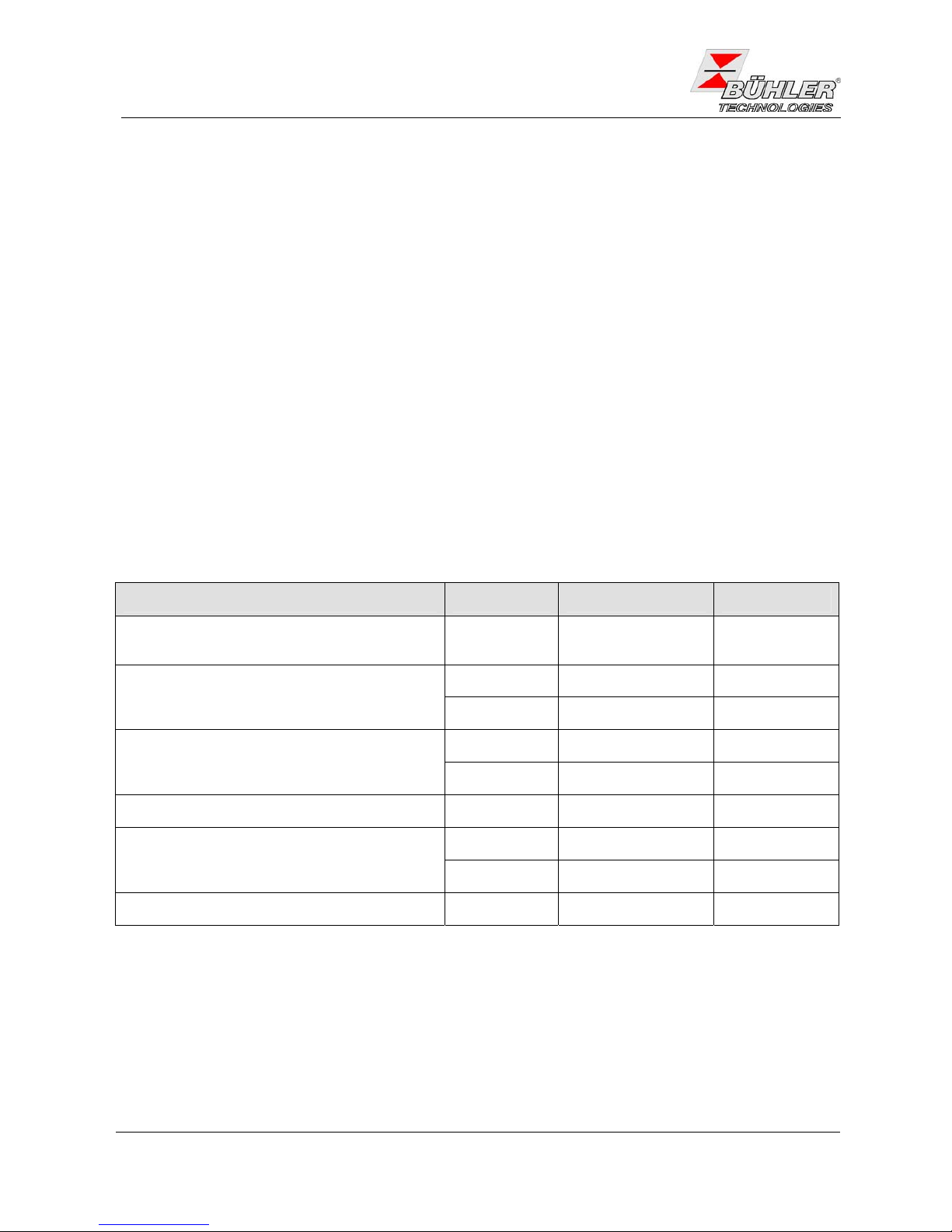
Problem / Störung mögliche Ursache Abhilfe
− Netzspannung unterbrochen − Netzanschluss vornehmen; Sitz
des Netzsteckers überprüfen
Keine Anzeige
− Sicherung defekt − Sicherung überprüfen u. ggf.
wechseln
Kühler läuft nicht an
− Zu hohe Temperatur am Kom-
pressorgehäuse
− abkühlen lassen und für ausreichende Belüftung sorgen
Alarm-LED blinkt bei
− Kühlleistung zu gering, obwohl
der Kühler arbeitet
− Unbedingt darauf achten, dass
Lüftungsschlitze nicht ver- deckt
werden (Wärmestau)
− Zu große Durchflussmenge / zu
hoher Taupunkt / Gastemperatur
− Grenzparameter einhalten / Vorabscheider vorsehen
− Übertemperatur
− Stillstand des eingebauten Venti-
lators
− überprüfen, ggf. austauschen
− Untertemperatur − Regelung defekt − Kühler einsenden
− Kondensatsammelgefäß voll − Kondensatsammelgefäß entlee-
ren
− Evtl. Festsitzen des Ventils im
autom. Kondensatableiter
− In beide Richtungen spülen
Kondensat im Gasausgang
− Kühler überlastet − Grenzparameter einhalten
− Gaswege verstopft − Wärmetauscher demontieren und
reinigen
Verminderter Gasdurchsatz
− Kondensatausgang vereist − Kühler einsenden
Page 9
Bedienungs- und Installationsanleitung
Installation- and Operation Instruction
Meßgaskühler / Sample Gas Coolers PKE-42
6.2 Sicherheitshinweise
GEFAHR
Elektrische Spannung
Gefahr eines elektrischen Schlages.
Trennen Sie das Gerät bei allen Arbeiten vom Netz. Sichern Sie das Gerät
gegen unbeabsichtigtes Wiedereinschalten.
Das Gerät darf nur von instruiertem, fachkundigem Personal geöffnet werden.
GEFAHR
Giftiges, ätzendes Gas / Kondensat
Messgas / Kondensat kann gesundheitsgefährdend sein.
Unterbrechen Sie bei allen Wartungs- und Reparaturarbeiten die Gaszufuhr.
Schützen Sie sich bei der Wartung vor giftigen / ätzenden Gasen / Kondensat.
Tragen Sie die entsprechende Schutzausrüstung.
6.3 Auswechseln der Feinsicherung Messgaskühler
¾ Kühler von der Netzspannung trennen!
¾ Isolationskappe vom Sicherungshalter an der Vorderseite des Kühlers nehmen. Hierzu die Kappe mit
einem Schraubendreher vorsichtig eindrücken und eine Vierteldrehung nach links drehen.
¾ Sicherung austauschen und Kappe durch Andrücken und Rechtsdrehung wieder aufsetzen. Beachten
Sie die Netzspannung für die Auswahl der richtigen Sicherung (s.
6.7)
¾ Spannungsversorgung durch Aufstecken der Steckverbindung wieder herstellen.
6.4 Auswechseln der Feinsicherung der peristaltischen Pumpe
¾ Pumpe von der Netzspannung trennen.
¾ Isolationskappe vom Sicherungshalter am Befestigungswinkel der Pumpe abnehmen. Hierzu die kap-
pe mit einem Schlitzschraubedreher eindrücken und eine Vierteldrehung nach links drehen.
¾ Sicherung austauschen und Kappe durch Andrücken und Rechtsdrehung wieder aufsetzen.
¾ Spannungsversorgung wieder herstellen.
6.5 Austausch des Schlauches der peristaltischen Pumpe (wenn Pumpe vorhanden)
¾ Gaszufuhr abstellen. Kondensatreste aus den Schläuchen abpumpen.
¾ Pumpe von der Spannungsversorgung trennen.
¾ Zu- und Abführungsschlauch an der Pumpe entfernen
¾ Mittlere Rändelschraube lösen, aber nicht ganz abdrehen. Schraube nach unten klappen.
¾ Abdeckkappe abziehen.
¾ Anschlüsse seitlich herausziehen und Schlauch entfernen.
¾ Schlauch wechseln und zur Montage obige Schritte in umgekehrter Reihenfolge durchführen
BX440009, 10/2008 Art. Nr. 90 31 100
9
Page 10
Bedienungs- und Installationsanleitung
Installation- and Operation Instruction
Meßgaskühler / Sample Gas Coolers PKE-42
10
BX440009, 10/2008 Art. Nr. 90 31 100
6.6 Demontage und Reinigung des Wärmeaustauschers
Wärmetauscher müssen nur ausgetauscht oder gewartet werden, wenn sie verstopft oder beschädigt sind.
Sollten sie sich zugesetzt haben, empfehlen wir zu prüfen, ob sich dies in Zukunft durch den Einsatz eines
Filters vermeiden lässt.
¾ Kühler von der Spannungsversorgung trennen und Gaszufuhr abstellen.
¾ Gasverbindungen und Kondensatablauf lösen. Kondensat auffangen.
¾ Wärmetauscher nach oben herausziehen.
¾ Kühlnest (Loch im Kühlblock) reinigen.
¾ Wärmetauscher spülen, bis alle Verunreinigungen beseitigt sind.
¾ Wärmetauscher an der gekühlten Außenfläche mit Silikonfett einschmieren.
¾ Wärmetauscher mit drehender Bewegung in das Kühlnest wieder einschieben.
¾ Gasverbindung und Kondensatablauf wiederherstellen.
¾ Spannungsversorgung wieder herstellen.
6.7 Ersatzteile und Zusatzteile
Bei Ersatzteilbestellungen bitten wir Sie, Kühlertyp und Seriennummer anzugeben. Bauteile für Nachrüstung
und Erweiterung finden Sie im angehängten Datenblatt und in unserem Katalog.
Ersatzteil Artikel-Nr.
Ersatzschlauch für peristaltische Pumpe 0,3 l/h
(nur notwendig, wenn Pumpe eingebaut)
91 24 03 00 27
230V 44 10 030 Lüfter
115V 44 00 030
230V 91 00 01 00 81 Elektronikplatine
115V 91 00 01 00 99
Temperaturanzeige 44 00 003
230 V 5x20 mm, 1 A träge 91 100 00 011 Feinsicherung Kühler
115 V 5x20 mm, 4 A träge 91 100 00 051
Feinsicherung peristaltische Pumpe 230 V / 115 V 5x20 mm, 1 A flink 91 100 00 061
6.8 Beiliegende Unterlagen
− Datenblatt DD 44 0011
− Konformitätserklärung KX 44 0001
Page 11

Bedienungs- und Installationsanleitung
Installation- and Operation Instruction
Meßgaskühler / Sample Gas Coolers PKE-42
1 Introduction
The sample gas coolers of model series PKE42 are designed for installation in gas analysis systems. Check
technical data according to the datasheets attached with regard to the specific application, used material combinations, as well as pressure- and temperature limits.
2 Important Advice
Operation of the device is only valid if
− the product is used under the conditions described in the installation- and operation instruction, the inten-
ded application according to the type plate and the intended use,
− the performance limits given in the datasheets and in the installation- and operation instruction are obey-
ed,
− monitoring devices and safety devices are installed properly,
− service and repair is carried out by Bühler Technologies GmbH,
− only original spare parts are used.
This manual is part of the equipment. The manufacturer keeps the right to modify specifications without advanced notice. Keep this manual for later use.
Definitions for warnings:
NOTE
Signal word for important information to the product.
CAUTION
Signal word for a hazardous situation with low risk, resulting in damaged to the device or
the property or minor or medium injuries if not avoided.
WARNING
Signal word for a hazardous situation with medium risk, possibly resulting in severe injuries
or death if not avoided.
DANGER
Signal word for an imminent danger with high risk, resulting in severe injuries or death if
not avoided.
Warning against hazardous
situation
Warning against possible
explosive atmospheres
disconnect from
mains
Warning against electrical
voltage
Warning against hot surface
wear respirator
Warning against respiration
of toxic gases
wear face protection
Warning against acid and
corrosive substances
wear gloves
BX440009, 10/2008 Art. Nr. 90 31 100
11
Page 12

Bedienungs- und Installationsanleitung
Installation- and Operation Instruction
Meßgaskühler / Sample Gas Coolers PKE-42
2.1 General indication of risk
Check all relevant safety regulations and technical indications for the specific installation place. Prevent failures and protect persons against injuries and the device against damage.
The person responsible for the system must secure that:
− safety and operation instructions are accessible and followed,
− local safety regulations and standards are obeyed,
− performance data and installation specifications are regarded,
− safety devices are installed and recommended maintenance is performed,
− national regulations for disposal of electrical equipment are obeyed.
Maintenance and repair
− Repairs on the device must be carried out by Bühler authorized persons only.
− Only perform modifications, maintenance or mounting described in this manual.
− Only use original spare parts.
During maintenance regard all safety regulations and internal operation instructions.
DANGER
Electrical voltage
Electrocution hazard.
Disconnect the device from power supply. Make sure that the equipment
cannot be reconnected to mains unintentionally.
The device must be opened by trained staff only.
DANGER
Toxic and corrosive gases
Sample gas can be hazardous.
Take care that the gas is exhausted in a place where no persons are in danger.
Protect yourself during maintenance against toxic / corrosive gases. Use
gloves, respirator and face protector under certain circumstances.
DANGER
Explosion hazard if used in hazardous areas
The device is
not suitable for operation in hazardous areas with potentially
explosive atmospheres.
Do not expose the device to combustible or explosive gas mixtures.
12
BX440009, 10/2008 Art. Nr. 90 31 100
Page 13

Bedienungs- und Installationsanleitung
Installation- and Operation Instruction
Meßgaskühler / Sample Gas Coolers PKE-42
3 Installation and Connection
The PKE-42 sample cooler is to be attached to vertical panels. The heat exchangers either made from
stainless steel, glass or PVDF are inserted from the top. Make sure, that there is enough space left above and
under the cooler to get the pipes/or hoses connected to the unit.
The place of installation must be weather shielded and air shall circulate freely around the cooler. The ambient
temperature shall not exceed the range from +5 to +50°C (+41 to +122°F) for the PKE-42.
Free air circulation must be provided. On both sides a gap of at least 10 cm (4 inches) must be kept clear.
Free air circulation must also be provided if the cooler is installed inside a cabinet. In some cases a fan is nec-
essary to establish sufficient circulation within the cabinet.
3.1 Mounting
Depending on the application parameters the connecting pipes or hoses must be of adequate material and
fastened tight. Connect the hoses to the heat exchangers made of duran glass with care to avoid breaking the
glass.
Make sure that all sample gas lines leading to the cooler are installed with downward slope to enable condensate flow into the heat exchanger by gravity.
In some applications with very high condensate content separators upstream the cooler could become necessary (see catalogue for appropriate types).
The gas entrance is marked with red.
If the sample gas pump is located upstream of the cooler, the condensate can be drained off by automatic
condensate drains. If the pump is located downstream peristaltic pumps or condensate vessels must be used
for removal (see our catalogue for appropriate equipment).
Important: The PVDF heat exchanger type DTV cannot be used with automatic drainers but with peristaltic
pumps only.
The condensate drains can be attached directly to such coolers with stainless steel heat exchangers. In case
of glass heat exchangers the condensate drains must be connected with flexible lines fixed with by brackets
separately.
The condensate lines must be installed with considerable slope and should not have less than 8 mm (0,3 inch)
inner diameter.
3.2 Electrical connection
WARNING
The device must be installed by trained staff only.
CAUTION
Wrong mains voltage may damage the device.
Regard the correct mains voltage as given on the type plate.
BX440009, 10/2008 Art. Nr. 90 31 100
13
Page 14

Bedienungs- und Installationsanleitung
Installation- and Operation Instruction
Meßgaskühler / Sample Gas Coolers PKE-42
WARNING
Damage to the device in case of insulation testing
Do not proceed insulation tests with high voltage to the device as a whole.
The device is equipped with extensive EMC protection. If insulation tests are carried out the electronic filter
devices will be damaged. All necessary tests have been carried out for all concerned groups of components at
the factory (test voltage 1 kV or 1.5 kV respectively, depending on the device).
The device is equipped with connectors according to DIN 43650. After correct wiring the connectors cannot be
interchanged and must be wired according to the following diagram (numbering can be found on the connector). Make sure the connector is correctly refitted after wiring.
Mains voltage is 230 VAC 50/60 Hz or 115 VAC 50/60 Hz (regard type plate).
If the cooler is equipped with peristaltic pumps, they must be connected to a separate power supply.
pin numbering
1
1
1
L1
N
2
2
2
3
3
3
PE
PE
PE
function ok
alarm
power supply
stat us output
4 Operation and Maintenance
4.1 Indication of risk
− All repairs must be carried out by Bühler authorised personnel only.
− Only perform modifications, servicing or mounting described in this manual.
− Only use original spare parts.
− Regard all relevant safety regulations and internal operating instructions during maintenance.
DANGER
Electrical voltage
Electrocution hazard.
Before any manipulation on the device, disconnect the electrical equipment
from mains power supply. Make sure that the electrical equipment cannot be
reconnected during repair or maintenance.
The wiring must be done by trained staff only. Regard the correct mains
voltage.
14
BX440009, 10/2008 Art. Nr. 90 31 100
Page 15

Bedienungs- und Installationsanleitung
Installation- and Operation Instruction
Meßgaskühler / Sample Gas Coolers PKE-42
DANGER
Toxic, corrosive gases
Sample gas may be harmful.
Please exhaust sample gas to a safe place.
Protect yourself against toxic / corrosive gas during maintenance. Use gloves,
respirator and face protector under certain circumstances.
4.2 Operation
After turning on the power supply the display will show the present temperature of the cooling block. The
status-LED is blinking until the unit has reached the operational temperature within the ±3K (± 5°F) range.
Then the LED will turn of and the output will switch to o.k.
If the status-LED starts blinking during the operation see “6.1 Troubleshooting“. For technical data see data
sheet.
4.3 Maintenance
The unit runs free of maintenance.
If the cooler has already mounted peristaltic pumps (optional), their tubes have to be checked regularly. Re-
placement is described in chapter 6.3.
5 Repair and Disposal
5.1 Repair
If the device shows irregularities see chapter 6 for troubleshooting
If you need help or more information
call +49(0)2102-498955 or your local agent.
If the device doesn’t work correctly after elimination of failures and turning power on, the device must be
checked by the manufacturer. Please ship the device with suitable packing to
Bühler Technologies GmbH
- Service Harkortstraße 29
40880 Ratingen
Germany
5.2 Disposal
The device contains no coolants. Regard the local regulations for disposal of electronic equipment.
BX440009, 10/2008 Art. Nr. 90 31 100
15
Page 16

Bedienungs- und Installationsanleitung
Installation- and Operation Instruction
Meßgaskühler / Sample Gas Coolers PKE-42
16
BX440009, 10/2008 Art. Nr. 90 31 100
6 Appendices
6.1 Trouble shooting
Problem / Failure Possible cause Solution
− no power − check power supply
No display
− fuse blown − Check fuse and change it if nec-
essary
Cooler not running
high temperature at the compressor
casing
wait until cooled off and care for
enough ventilation
Status-LED blinks with
− Cooling capacity to low, even
though cooler is running
− Make sure that air can circulate
free and that ventilation louvres
are not obstructed
− gas flow / dew point / gas temperature to high
− check application parameters,
install pre-separator
− High Temperature
− fan broken − check fan, replace if necessary
− Low temperature − controller defect − send cooler for inspection
− condensate vessel full − drain vessel
− stuck valve in automatic conden-
sate drain
− flush both directions
Condensate in gas outlet
− cooler overloaded − check limiting parameters
− clogged gas path − check / flush heat exchanger
Reduced gas flow
− condensate outlet clogged by ice − send cooler for inspection
Page 17

Bedienungs- und Installationsanleitung
Installation- and Operation Instruction
Meßgaskühler / Sample Gas Coolers PKE-42
6.2 Safety Advice
DANGER
Electrical voltage
Electrocution hazard.
Disconnect the device from power supply. Make sure that the equipment
cannot be reconnected to mains unintentionally.
The device must be opened by trained staff only.
DANGER
Toxic and corrosive gases / condensate
Sample gas / condensate can be hazardous.
Shut off gas supply prior to maintenance or repairs.
Protect yourself during maintenance against toxic / corrosive gases /
condensate. Use gloves, respirator and face protector under certain
circumstances.
6.3 Replacing the Fuse of the Cooler
¾ Disconnect cooler from power supply
¾ Remove the black cap on the front side of the cooler holding the fuse. Use a screwdriver big enough
for pressing the cap and turn it counter-clockwise about 90 degrees.
¾ Replace the fuse recommended for the voltage of the cooler (See
6.7).
¾ Refit the cap by pressing it and turning it clockwise.
¾ Reconnect power supply.
6.4 Replacing the Fuse of the peristaltic Pump
¾ Disconnect the pump from the mains.
¾ Remove the insulation cover from the fuse holder at the pump’s mounting bracket. For this, push the
cover using a screw driver and quarter-turn it to the left.
¾ Replace the fuse and refit the insulation cover by quarter-turning it to the right.
¾ Reconnect the cooler to the mains.
6.5 Replacing the Hoses of the peristaltic Pump
¾ Shut off the gas supply and drain residual condensate from the hoses.
¾ Disconnect the pump from the mains.
¾ Remove the supplying and draining hoses from the pump.
¾ Loosen but don’t remove the centre knurled thumb screw. Push screw downwards.
¾ Remove cover
¾ Push terminals sidewards.
¾ Replace the hose and remount the pump in reverse order.
BX440009, 10/2008 Art. Nr. 90 31 100
17
Page 18

Bedienungs- und Installationsanleitung
Installation- and Operation Instruction
Meßgaskühler / Sample Gas Coolers PKE-42
18
BX440009, 10/2008 Art. Nr. 90 31 100
6.6 Cleaning of the heat exchanger
The heat exchanger must be replaced only in case of damage or when clogged. In the latter case we recommend to check if the use of a filter will avoid such clogging in the future.
¾ Disconnect the cooler from the mains and shut off gas supply.
¾ Loosen gas fittings and condensate drain fitting. Collect condensate.
¾ Pull out the heat exchanger upwards out of the cooler.
¾ Clean the cooling nest (hole in cooling block).
¾ Clean the heat exchanger until all impurities are disposed.
¾ Grease the heat exchanger on the cooling surfaces with silicone grease.
¾ Introduce the heat exchanger with turning movement into cooling nest.
¾ Re-establish fittings for gas tubes and condensate drain.
¾ Reconnect the cooler to the mains.
6.7 Spare parts
Please indicate with spare part requirements type of cooler and serial no.
For accessories and enhancement see data sheets and/or catalogue.
The following parts are recommended for stocking:
Spare part Part no.
Replacement hose for peristaltic pump 0.3 l/h
(only if your cooler is equipped with pump)
91 24 03 00 27
230V 44 10 030 Fan
115V 44 00 03 0
230V 91 00 01 00 81 Electronic board
115V 91 00 01 00 99
Temperature display 44 00 003
230 V 5x20 mm, 1 A slow blow 91 100 00 011 Fuse cooler
115 V 5x20 mm, 4 A slow blow 91 100 00 051
Fuse peristaltic pump 230 V / 115 V 5x20 mm, 1 A fast-acting 91 100 00 061
6.8 Attached documents
− Data sheet DE 44 0011
− Declaration of conformity KX 44 0001
Page 19

Der PKE 42 ist die leistungsstärkste Baugröße der Peltier-
§ Kompakte Abmessungen
kühler. In dem aus Aluminium gefertigten Kühlblock kommen
die gleichen Wärmetauscher zum Einsatz wie in den
§ Kurze Inbetriebnahmezeit
Kompressorkühlern. Auch hier stehen wahlweise solche aus
Edelstahl, Duranglas oder PVDF mit ein oder zwei
Gaswegen zur Verfügung.
§ Wartungsfrei
Der auf 5 °C voreingestellte Ausgangstaupunkt wird durch
§ Geringe Betriebsgeräusche
eine elektronische Regelung konstant gehalten.
Die Temperatur des Kühlblockes wird durch eine Anzeige in
§ Nennleistung 140 kJ/h
°C oder °F dargestellt. Diese wird durch eine Blink-LED für
Über- und Untertemperatur sowie einen Relaisausgang in
Fail-Safe-Schaltung ergänzt. Diese Statusausgaben
§ Taupunktstabilität 0,1°C
markieren einen Bereich von ±3K um den eingestellten
Ausgangstaupunkt. Der Relaisausgang kann z.B. zum
§ Statusanzeige und -ausgang
Steuern der Messgaspumpe verwendet werden, um ein
Zuschalten des Gasstroms erst bei Erreichen des zulässigen
§ Anzeige der Kühlblocktemperatur
Kühlbereiches zu ermöglichen.
Für das abgeschiedene Kondensat bieten wir je nach
§ Wärmetauscher mit 1 oder 2
Betriebsart des Aufbereitungssystems automatische
Gaswegen
Kondensatableiter oder peristaltische Pumpen an.
Peltier - Messgaskühler
PKE 42
DD 44 0011
09/2009
Seite 1/4
Bühler Technologies GmbH
D - 40880 Ratingen, Harkortstr. 29
Tel.: + 49 (0) 2102 / 49 89-0 Fax: + 49 (0) 2102 / 49 89-20
Internet: www.buehler-technologies.com
e-mail: analyse@buehler-technologies.com
Page 20

10
9
8
1
2
3
4
5
6
7
A000037X
ALARMAUSGANG
ALARMOUTPUT
NETZ
POWER
A000130D
320
337
148
017
91
2
,
5
2 ,
5
1 0
1
9
2
ø7
Alarm
C
05°
Betriebsbereitschaft nach max. 10 Minuten
Nennkühlleistung (bei 25 °C) 140 kJ/h
Umgebungstemperatur 5 bis 50 °C
Gasausgangstemperatur voreingestellt 5 °C
Taupunktschwankungen statisch 0,1 K
Im gesamten Spezifikationsbereich ± 1,5 K
Netzanschluss 115 V oder 230 V
50/60 Hz, Stecker
nach DIN 43650
Leistungsaufnahme max. 350 VA
Statusausgang Schaltleistung max. 230 V AC, 150 V DC
2 A, 50 VA
potentialfrei
Anschluss Stecker nach DIN 43650
Schutzart IP 20
Gehäuse Edelstahl
Gewicht ca. 11 kg
1 Meßgassonde
2 Meßgasleitung
3 Umschalthahn
4 Meßgaspumpe
5 Meßgaskühler EGK-1/2
6 Automatischer Kondensatableiter oder peristaltische
Pumpe
7 Feuchtefühler
8 Feinstfilter
9 Strömungsmesser
10 Analysator
Typen und Daten der einzelnen Komponenten siehe
Datenblätter.
Typisches Installationsschema
Abmessungen (mm)
Testgas
Luft
Aus
Kondensat
Aus
Messgas
Ein / Aus
Luft
Ein
Technische Daten
DD 44 0011
09/2009
Seite 2/4
Page 21

0
20
40
60
80
100
120
140
160
kJ/h
5 10 15 20 25 30 35 40
°C
A000131D
180
200
45 50
3)
Wärmetauscher TS TG TV-SS DTS DTG DTV
1)
Durchfluß v 500 l/h 400 l/h 235 l/h 2 x250 l/h 2 x 200 l/h 2 x 160 l/h
max
1)
Eingangstaupunkt t 80 °C 80 °C 65 °C 80 °C 65 °C 65 °C
e,max
1)
Gaseingangstemp. J 180 °C 140 °C 140 °C 180 °C 140 °C 140 °C
G,max
Max. Kühlleistung Q 450 kJ/h 230 kJ/h 120 kJ/h 450 kJ/h 230 kJ/h 185 kJ/h
max
Gasdruck p 160 bar 3 bar 3 bar 25 bar 3 bar 2 bar
max
Differenzdruck Dp (v=150 l/h) 8 mbar 8 mbar 8 mbar je 5 mbar je 5 mbar je 15 mbar
Totvolumen V 69 ml 48 ml 129 ml 28 / 25 ml 28 / 25 ml 21 / 21 ml
tot
2)
Anschlüsse Gas G 1/4“ i GL 14 DN 4/6 Rohr 6 mm GL 14 DN 4/6
2)
Kondensatablaß G 3/8“ i GL 25 G3/8" i Rohr 10 mm GL 18 DN 4/6
1)
Unter Berücksichtigung der maximalen Kühlleistung des Kühlers
2)
NPT-Gewinde auf Anfrage
3)
Kondensatableitung nur mit Pumpe möglich
Wärmetauscher
Die Energie des Meßgases und damit in erster Näherung die abgeforderte Kühlleistung Q wird bestimmt durch die drei
Parameter Gastemperatur J , Taupunkt t (Feuchtigkeitsgehalt) und Volumenstrom v. Physikalisch bedingt steigt bei
G e
wachsender Gasenergie der Ausgangstaupunkt. Die zulässige Energiebelastung durch das Gas wird somit bestimmt durch die
tolerierte Anhebung des Taupunktes.
Nachfolgende Grenzen sind festgelegt für einen Normarbeitspunkt von t =50°C und J =70°C. Angegeben wird der maximale
e G
Volumenstrom v in Nl/h gekühlter Luft, also nach dem Auskondensieren des Wasserdampfes.
max
Werden die Parameter t und J unterschritten, kann der Volumenstrom v angehoben werden. Beispielsweise kann beim TG
e G max
auch statt t = 50 °C, J =70°C und v= 345 l/h das Parametertripel t =40°C, J = 70°C und v= 425 l/h gefahren werden.
e G e G
Bitte nehmen Sie bei Unklarheiten unsere Beratung in Anspruch, oder nutzen Sie unser Auslegungsprogramm..
Leistungskurven
Umgebungstemperatur
Kühlleistung
PKE 42
mit DTS
Grenze für
TV-SS
DD 44 0011
09/2009
Seite 3/4
Page 22

4 4 7 0 0 0
0
1
2
0 0 0
1 1 0
1 2 0
1 3 0
2 6 0
2 7 0
2 8 0
0
1
PKE 42
Automatischer Kondensatableiter AK 5.2
Kondensatsammelgefäß GL1, 0,4l
Peristaltische Pumpe 0,3 l/h, 230V, zur separaten Montage
Peristaltische Pumpe 0,3 l/h, 115V, zur separaten Montage
Art.Nr.
Spannung
115 V
230 V
Gasweg/ Material/ Version
Ohne Wärmetauscher
1 Gasweg/ Einzel WT Edelstahl/ TS
1 Gasweg/ Einzel WT Glas/ TG
1 Gasweg/ Einzel WT PVDF/ TV SS
2 Gaswege/ Doppel WT Edelstahl/ DTS
2 Gaswege/ Doppel WT Glas/ DTG
1)
2 Gaswege/ Doppel WT PVDF/ DTV
2)
Kondensatableitung
Ohne Kondensatableitung
3)
Peristaltische Pumpe(n)
Bestellhinweise
Die genaue Artikelnummer der von Ihnen definierten Type ermittelt sich aus dem nachfolgenden Typenschlüssel.
Bitte beachten: Jeder einzelne Gasweg ist mit einer peristaltischen Pumpe oder einem Kondensatableiter auszurüsten
Technische Änderungen vorbehalten
DD 44 0011
09/2009
Seite 4/4
1)
Kondensatauslässe nur für Anschluss von peristaltischen Pumpen geeignet
2)
Auch peristaltische Pumpen zur separaten Montage verfügbar
3)
Jeder Gasweg ist mit einer peristaltischen Pumpe ausgestattet. Die Versorgungsspannung entspricht der des Grundgerätes.
Zubehör
451 00 08
441 00 05
912 40 30 104
912 40 30 105
Page 23

Sample Gas Cooler
PKE 42
DE 44 0011
09/2009
Page 1/4
The PKE 42 cooling system consists of semiconductor Peltier
§ Quick installation
cooling elements with an aluminum cooling block. Fitted into
the block is a removable, high-efficiency heat exchanger
made of stainless steel, DURAN-glass or PVDF with 1 or 2
§ No maintenance required
gas paths.
§ Low noise
The unit maintains a constant outlet dew point of 40 °F with
an electronic controller. The temperature of the cooling block
§ Efficient heat exchangers made of
is shown on an LED-display. The status is indicated by a
flashing LED which shows high or low temperature alarms
stainless steel, Duran-glass or PVDF
and operates together with relay to halt the flow of sample gas
in fail-safe mode.
§ Nominal cooling capacity 140 kJ/h
The relay maybe used to control the sample gas pump when
the cooler reaches the desired temperature range.
§ Dew point stability 0.1°C
Condensate is removed either by peristaltic pumps, by
§ Status display and output
automatic condensate drains, or condensate vessels.
§ Cooling temperature display
§ Heat exchanger with 1 or 2 gas paths
§ Compact design
Bühler Technologies GmbH
D - 40880 Ratingen, Harkortstr. 29
Tel.: + 49 (0) 2102 / 49 89-0 Fax: + 49 (0) 2102 / 49 89-20
Internet: www.buehler-technologies.com
e-mail: analyse@buehler-technologies.com
Page 24

10
9
8
1
2
3
4
5
6
7
A000037X
ALARMAUSGANG
ALARMOUTPUT
NETZ
POWER
A000130D
320
337
148
017
91
2
,
5
2 ,
5
1 0
1
9
2
ø7
Alarm
C
05°
Technical Data
Ready for operation after max. 10 minutes
Cooling capacity (at 25°C) 140 kJ/h
Ambient temperature +5 °C to 50 °C
Factory set dew point 5 °C
Dew point noise static 0.1 K
Drift over full specified range ± 1.5 K
Power supply 115 V or 230 V ,50/60 Hz, plug acc. to DIN 43650
Power consumption max. 350 VA
Status output Electrical spec. max. 230V AC, 150 VDC
2A, 50 VA
free of potential
Plug acc. to DIN 43650
Protection class IP 20
Housing stainless steel
Weight approx. 11 kg
Typical Installation Diagram:
Dimensions (mm)
1 Sample probe
2 Sample tube
3 3 way valve
4 Sample gas pump
5 Sample gas coole EGK-1/2
6 Automatic condensate drain or perist. pump
7 Moisture detector
8 Fine filter
9 Flow meter
10 Analyser
For models and specs of components see individual data
sheets.
calibration gas
air
out
condensate
out
sample gas
in / out
air
in
DE 44 0011
09/2009
Page 2/4
Page 25

0
20
40
60
80
100
120
140
160
kJ/h
5 10 15 20 25 30 35 40
°C
A000131D
180
200
45 50
ambient temperature
coolong capacity
PKE 42
with DTS
Limits for
TV-SS
3)
Heat Exchanger TS TG TV-SS DTS DTG DTV
1)
Flow rate v 500 l/h 400 l/h 235 l/h 2 x 250 l/h 2 x 200 l/h 2 x 160 l/hI
max
1)
Inlet dewpoint t 80 °C 80 °C 65 °C 80 °C 65 °C 65 °C
e,max
1)
Gas inlet temperature. J 180 °C 140 °C 140 °C 180 °C 140 °C 140°C
G,max
Max. cooling capacity Q 450 kJ/h 230 kJ/h 120 kJ/h 450 kJ/h 230 kJ/h 185 kJ/h
max
Gas pressure p 160 bar 3 bar 3 bar 25 bar 3 bar 2 bar
max
Pressure drop Dp (v=150 l/h) 8 mbar 8 mbar 8 mbar each 5 mbar each 5 mbar each 15 mbar
Dead volume V 69 ml 48 ml 129 ml 28 / 25 ml 28 / 25 ml 21 / 21 ml
tot
2)
Sample gas connections G 1/4“ i GL 14 DN 4/6 tube 6 mm GL 14 DN 4/6
2)
Condensate out connections G 3/8“ i GL 25 G 3/8" i tube 10 mm GL 18 DN 4/6
1)
max. cooling capacity of the cooler must be considered
2)
NPT-threads upon request
3)
Con only be used with peristaltic pumps
Heat Exchanger
The energy content of the sample gas and, as a result, the required cooling capacity of the gas cooler is determined by 3
parameters: gas temperature J , dewpoint t (moisture content) and flow v. The outlet dew point rises with increasing energy
G e
content (heat) of the gas. The required cooling capacity is determined by the maximum acceptable level of the outlet dew point.
The following table shows cooler performance assuming the following conditions: t =50°C and J =70°C. Indicated is the v in
e G max
Nl/h cooled air (i.e. after the moisture has condensated). If the actual values stay below the parameters t and J , v can be
e G max
increased. For example (TG), instead of t = 50°C, J = 70°C and v = 345 l/h the values t =40°C, J =70°C and a maximum flow
e G e G
rate of v=425 l/h could be achieved.
Please contact one of Buhler’s application specialists for assistance and further information.
Performance Data
DE 44 0011
09/2009
Page 3/4
Page 26

4 4 7 0 0 0
0
1
2
0 0 0
1 1 0
1 2 0
1 3 0
2 6 0
2 7 0
2 8 0
0
1
PKE 42
Power Supply
115 V
230 V
Gas Path/ Material/ Version
without heat exchanger
single path heat exchanger TS, stainless steel
single path heat exchanger TG, glass
single path heat exchanger TV SS, PVDF
dual path heat exchanger DTS, stainless steel
dual path heat exchanger DTG, glass
1)
dual path heat exchanger DTV , PVDF
1)
Condesate Discharge
without condensate discharge
3)
peristaltic pump(s)
Automatic condensate drain AK 5.2
Condensate vessel GL1, 0,4l
Peristaltic pump 0.3 l/h, 230V, for separate mounting
Peristaltic pump 0.3 l/h, 115V, for separate mounting
1)
Condensate outlet only suitable for connecting peristaltic pumps
2)
Peristaltic pumps for separate mounting available
3)
Each gas path is equipped with a peristaltic pump with the same mains supply requirements as the cooler.
Please indicate with order
Please extract the part number for the cooler fulfilling your requirements from the type code below.
Please note: Each gas path should be equipped with a peristaltic pump or an automatic condensate drain.
Part No.
DE 44 0011
09/2009
Page 4/4
We reserve the right to amend specification.
Accessories
451 00 08
441 00 05
912 40 30 104
912 40 30 105
Page 27

Sample Gas Cooler
PKE 42
The PKE 42 cooling system consists of semiconductor Peltier
cooling elements with an aluminum cooling block. Fitted into
the block is a removable, high-efficiency heat exchanger
made of stainless steel, DURAN-glass or PVDF with 1 or 2
gas paths.
The unit maintains a constant outlet dew point of 40 °F with
an electronic controller. The temperature of the cooling block
is shown on an LED-display. The status is indicated by a
flashing LED which shows high or low temperature alarms
and operates together with relay to halt the flow of sample gas
in fail-safe mode.
The relay maybe used to control the sample gas pump when
the cooler reaches the desired temperature range.
Condensate is removed either by peristaltic pumps, by
automatic condensate drains, or condensate vessels.
§ Compact design
§ Quick installation
§ No maintenance required
§ Low noise
§ Efficient heat exchangers made of
stainless steel, Duran-glass or PVDF
§ Nominal cooling capacity 133 Btu/hr
§ Dew point stability 0.2°F
§ Status display and output
§ Cooling temperature display
§ Heat exchanger with 1 or 2 gas paths
DA 440011
09/2009
Page 1/4
Buhler Technologies LLC
1030 West Hamlin Road, Rochester Hills, MI 48309
Phone: 248.652.1546 Fax: 248.652.1598
Internet: www.buhlertech.com
e-mail: sales@buhlertech.com
Page 28

10
9
8
1
2
3
4
5
6
7
A000037X
ALARMAUSGANG
ALARMOUTPUT
NETZ
POWER
A000130E
12.6”
13.3”
5.8”
6
7”.
7
6
”
.
7
4.
”
7 6
”
.
ø0.3”
Technical Data
Ready for operation After max. 10 minutes
Cooling capacity (at 75°F) 133 Btu/hr
Ambient temperature 40 °F to 120 °F
Factory set dew point 5 °C (40 °F)
Dew point noise static 0.1 K
Drift over full specified range ± 1.5 K
Power supply 115 V or 230 V, 50/60Hz, plug DIN 43650
Power consumption max. 350 VA
Status output Electrical spec. max. 230 V AC, 150 V DC
2 A, 50 VA
dry contacts
Plug DIN 43650
Protection class IP 20
Housing Stainless Steel
Weight approx. 24 lb.
1 Sample probe
2 Sample tube
3 3 way valve
4 Sample gas pump
5 Sample gas cooler EGK-1/2
6 Automatic condensate drain or perist. pump
7 Moisture detector
8 Fine filter
9 Flowmeter
10 Analyzer
For models and specs of components see individual data
sheets.
Typical Installation Diagram:
Dimensions (inch)
Sample gas/
Calibration gas
air
out
condensate
out
sample gas
in / out
air
in
DA 440011
09/2009
Page 2/4
Page 29

0
20
40
60
80
100
120
140
160
180
btu/h
40 50 60 70 80 90 100 110 120
°F
A00
PKE 42
fitted with
DTS
Limit for
TV-SS
Cooling capacity
Ambient temperature
3)
Heat Exchanger TS TG TV-SS DTS DTG DTV
1)
Flow rate v 8.3 lpm 6.7 lpm 3.9 lpm 2 x 4.2 lpm 2 x 3.3 lpm 2 x 2.7 lpm
max
1)
Inlet dewpoint t 175 °F 175 °F 150 °F 175 °F 150 °F 150 °F
e,max
1)
Gas inlet temperature. J 355 °F 285 °F 285 °F 355 °F 285 °F 285°F
G,max
Max. cooling capacity Q 427 Btu/hr 218 Btu/hr 114 Btu/hr 427 Btu/hr 218 Btu/hr 175 Btu/hr
max
Gas pressure p 2321 psig 44 psig 44 psig 363 psig 44 psig 29 psig
max
Pressure drop Dp (v=2.5 lpm) 0.12 psig 0.12 psig 0.12 psig each 0.07 psig each 0.07 psig each 0.22 psig
Dead volume V 4.2 cu. in. 2.9 cu. in. 7.9 cu. in. 1.7 / 1.5 cu. in. 1.7 / 1.5 cu. in. 1.3 / 1.3 cu. in.
tot
2)
Sample gas connections G 1/4“ i GL 14 DN 4/6 tube 6 mm GL 14 DN 4/6
2)
Condensate outlet connections G 3/8“ i GL 25 G 3/8" i tube 10 mm GL 18 DN 4/6
1) 2) 3)
Max. cooling capacity of the cooler must be considered NPT-threads upon request Can only be used with peristaltic pumps
Heat Exchanger
The energy content of the sample gas and, as a result, the required cooling capacity of the gas cooler is determined by 3 parameters: gas
temperature J , dewpoint t (moisture content) and flow v. The outlet dew point rises with increasing energy content (heat) of the gas. The
G e
required cooling capacity is determined by the maximum acceptable level of the outlet dew point.
The following table shows cooler performance assuming the following conditions: t =120°F and J =160°F. Indicated is the v in lpm cooled
e G max
air (i.e. after the moisture has condensed).If the actual values stay below the parameters t and J , v can be increased. For example (TG),
e G max
instead of t = 120°F, J = 160°F and v = 5.7 lpm the values t =105°F, J =160°F a maximum flow rate of v=7.1 lpm could be achieved.
e G e G
Please contact one of Buhler’s application specialists for assistance and further information.
DA 440011
09/2009
Page 3/4
Performance Data
Page 30

4 4 7 0 0 0
0
1
2
0 0 0
1 1 0
1 2 0
1 3 0
2 6 0
2 7 0
2 8 0
0
1
PKE 42
Power Supply
115 V
230 V
Gas Path/ Material/ Version
without heat exchanger
single path heat exchanger TS, stainless steel
single path heat exchanger TG, glass
single path heat exchanger TV SS, PVDF
dual path heat exchanger DTS, stainless steel
dual path heat exchanger DTG, glass
1)
dual path heat exchanger DTV , PVDF
1)
Condesate Discharge
without condensate discharge
3)
peristaltic pump(s)
1)
Condensate outlet only suitable for connecting peristaltic pumps
2)
Peristaltic pumps for separate mounting available
3)
Each gas path is equipped with a peristaltic pump with the same mains supply requirements as the cooler.
Please indicate with order
Please extract the part number for the cooler fulfilling your requirements from the type code below.
Please note: Each gas path should be equipped with a peristaltic pump or an automatic condensate drain.
Part No.
DA 440011
09/2009
Page 4/4
We reserve the right to amend specifications.
Automatic condensate drain AK 5.2
Condensate vessel GL1, 0,4l
Peristaltic pump 0.3 l/h, 230V, for separate mounting
Peristaltic pump 0.3 l/h, 115V, for separate mounting
Accessories
451 00 08
441 00 05
912 40 30 104
912 40 30 105
Page 31

EU-Konformitätserklärung gemäß EN 45014
EU-declaration of conformity according to EN 45014
Datum
Bühler Mess- und Regeltechnik GmbH, Harkortstr. 29, D-40880 Ratingen,
Tel. +49 (0) 21 02 / 49 89-0, Fax. +49 (0) 21 02 / 49 89-20
Email
: buehler@buehler-ratingen.com
KX 44 0001
Hiermit erklären wir, dass die nachfolgenden Produkte den wesentlichen Anforderungen
der folgenden Richtlinien in ihrer aktuellen Fassung entsprechen:
- Richtlinie 73/23/EWG über elektrische Betriebsmittel zur Verwendung innerhalb
bestimmter Spannungsgrenzen
- Richtlinie 89/336/EWG über die elektromagnetische Verträglichkeit
Herewith we declare that the following products correspond to the essential requirements of
- Directive 73 / 23 EWG about electrical equipment for use with certain limits of voltage,
- Directive 89 / 336 / EWG about electromagnetic compatibility,
Produkte / products
Messgaskühler / Sample gas coolers
(Fabrikat, make)
PKE 4, PKE 4 HA, PKE 42
(Typ, type),
Zur Beurteilung der Konformität wurden folgende harmonisierte Normen herangezogen:
The following harmonized standards have been used:
•
••
• EN 61000-6-3 (2001) - Elektromagnetische Vertäglichkeit- Fachgrundnorm Störaussendung
(Wohnbereich,Geschäfts und Gewerbebereich, Kleinbetriebe)
•
••
• EN 61000-6-2 (2001) - Elektromagnetische Störfestigkeit- Fachgrundnorm Störfestigkeit
(Industriebereich, 2001)
•
••
• EN 60204 –1 (1997) - Sicherheit von Maschinen - elektrische Ausrüstung von Maschinen –
Teil1: Allgemeine Anforderungen
•
••
• EN ISO 12100 (2004) - Sicherheit von Maschinen – allgemeine Gestaltungsgrundsätze, Teil 1 und 2
Ratingen, den 14. Februar 2005
________________________ __________________________________
G.R. Biller Stefan Eschweiler
Geschäftsführer – Managing Director Technischer Leiter – technical manager
 Loading...