

Page 1
Fluidcontrol
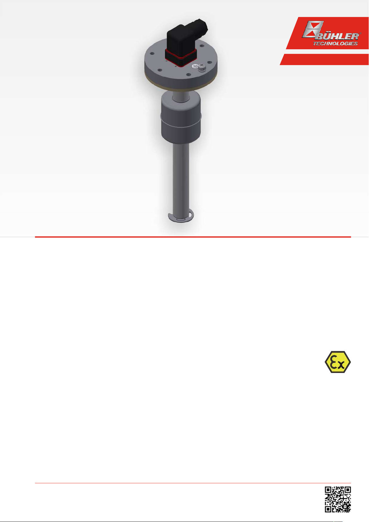
Level switch for tank installation
NT 61-Z0-Atex
Installation and Operation Instructions
Original instructions
BE100028
10/2017
Bühler Technologies GmbH, Harkortstr. 29, D-40880 Ratingen
Tel. +49 (0) 21 02 / 49 89-0, Fax: +49 (0) 21 02 / 49 89-20
E-Mail: fluidcontrol@buehler-technologies.com
Internet: www.buehler-technologies.com
Page 2
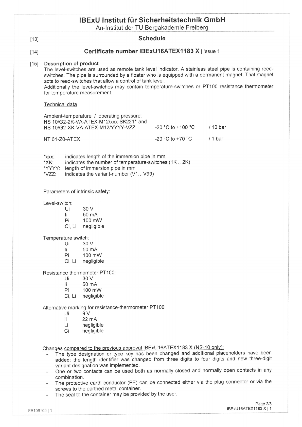
Bühler Technologies GmbH, Harkortstr. 29, D-40880 Ratingen
Tel. +49 (0) 21 02 / 49 89-0, Fax: +49 (0) 21 02 / 49 89-20
Internet: www.buehler-technologies.com
E-Mail: fluidcontrol@buehler-technologies.com
Read this instruction carefully prior to installation and/or use. Pay attention particularly to all advises and safety instructions to prevent injuries. Bühler Technologies can not be held responsible for misusing
the product or unreliable function due to unauthorised modifications.
All rights reserved. Bühler Technologies GmbH 2018
Document information
Document No..........................................................BE100028
Version.......................................................................... 10/2017
Part No.........................................................................9031269
Page 3

NT 61-Z0-Atex
Contents
1 Introduction..................................................................................................................................................................................................................... 2
1.1 Intended Use......................................................................................................................................................................................................... 2
1.2 Functionality......................................................................................................................................................................................................... 2
1.2.1 Fill level monitoring.............................................................................................................................................................................2
1.2.2 Temperature monitor .........................................................................................................................................................................2
1.3 Type plate ..............................................................................................................................................................................................................2
1.4 Model key............................................................................................................................................................................................................... 3
1.5 Scope of Delivery.................................................................................................................................................................................................. 3
2 Safety instructions.........................................................................................................................................................................................................4
2.1 Important advice................................................................................................................................................................................................. 4
2.2 General hazard warnings ................................................................................................................................................................................. 5
3 Transport and storage ..................................................................................................................................................................................................6
4 Installation and connection........................................................................................................................................................................................ 7
4.1 Installation............................................................................................................................................................................................................ 7
4.2 Electrical connections ........................................................................................................................................................................................ 7
4.2.1 PA connection (potential equalisation) .........................................................................................................................................7
4.2.2 Intrinsically-safe connection............................................................................................................................................................ 8
5 Operation and control ................................................................................................................................................................................................ 10
6 Cleaning and Maintenance........................................................................................................................................................................................12
7 Service and repair..........................................................................................................................................................................................................13
7.1 Spare parts and accessories ............................................................................................................................................................................13
8 Disposal........................................................................................................................................................................................................................... 14
9 Appendices......................................................................................................................................................................................................................15
9.1 Technical Data .....................................................................................................................................................................................................15
9.2 Standard pin assignment ................................................................................................................................................................................17
9.3 Definitions........................................................................................................................................................................................................... 18
10 Attached documents................................................................................................................................................................................................... 19
iBühler Technologies GmbHBE100028 ◦ 10/2017
Page 4
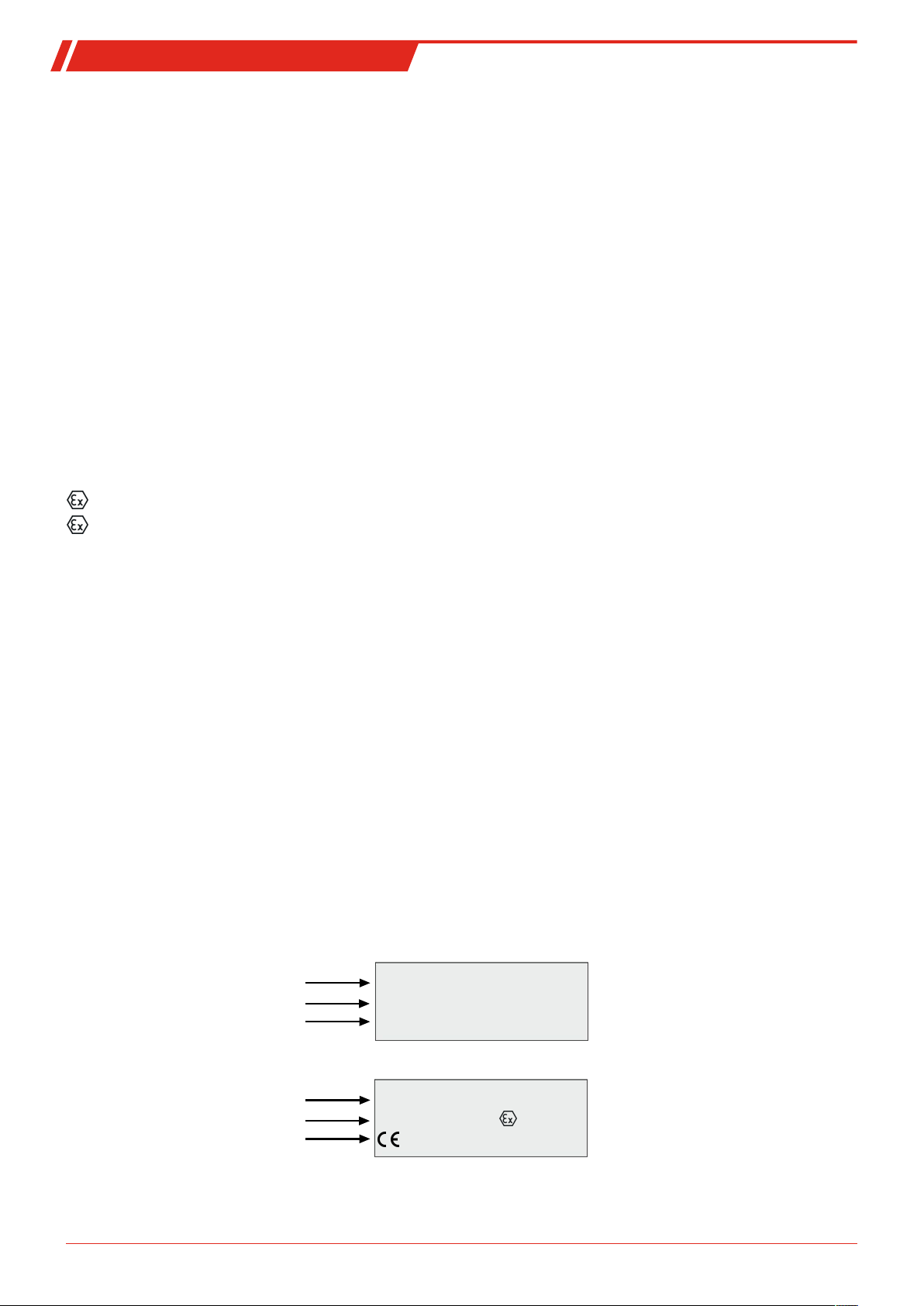
NT 61-Z0-Atex
Manufacturer
Serial no., item no., year of manufacture
Type designation
Bühler Technologies GmbH
10610799 KW: 18-2017 001
NT 61-Z0-2M12/...-...-...-ATEX
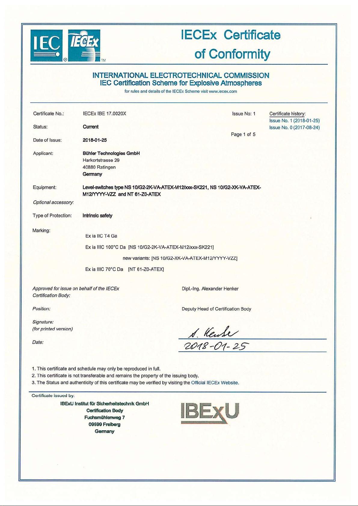
IECEx IBE 17.0020X
IBExU16ATEX1183 X
IECEx - CoC no.
IBExU no.
CE mark, no. of notified body
0158
1. Type plate:
2. Type plate:
1 Introduction
1.1 Intended Use
The level switch is used to monitor levels and temperatures inside a tank. The measuring tube is inside the tank during the process.
According to IEC/EN60079-11, NT61-Z0-Atex series level switches are simple electrical apparatuses without separate voltage
source intended for installation inside the tank.
When used in explosive areas this type may only be operated on intrinsically-safe circuits. When using intrinsically-safe connections they can be installed in Zone 1 explosive areas and the level or temperature be monitored in a Zone 0 environment. The intrinsically-safe power supply must be suitable for the zone. The limits inside these operating instructions must be observed.
Never the use level switches in highly flammable or corrosive liquids. The medium must not contain particles, particularly
metallic particles, to prevent deposits on the float or between the float and switching tube.
Before installing the level switch, verify the listed technical data meet the application parameters. Also observe the applicable
requirements of IEC/EN60079-14.
Further check if all contents are complete.
Please note the specific values of the level switch when connecting and the correct version when ordering spare parts.
The explosion protection markings on the level switches are:
II 1G Ex ia IIC T4 Ga
II 1D Ex ia IIIC T70°C Da
1.2 Functionality
1.2.1 Fill level monitoring
The measuring tube is located inside the tank. The level contacts (bistable reed contacts) are located inside the measuring tube.
These are activated by a magnet inside the level switch float. This can switch signals used to display the fill level.
The contacts clip onto a perforated rail spaced as specified in the purchase order and cannot be moved.
1.2.2 Temperature monitor
The temperature of a fluid is monitored via bimetal disc thermostat inside the level switch tube. When a set temperature is
reached, a bimetal snap disk inside the thermostat is triggered, which opens or closes an electrical contact. A Pt100 temperature
sensor can optionally be used in place of the bimetal thermostat.
Please note the technical data in the appendix.
1.3 Type plate
Example:
2 Bühler Technologies GmbH BE100028 ◦ 10/2017
Page 5
NT 61-Z0-Atex
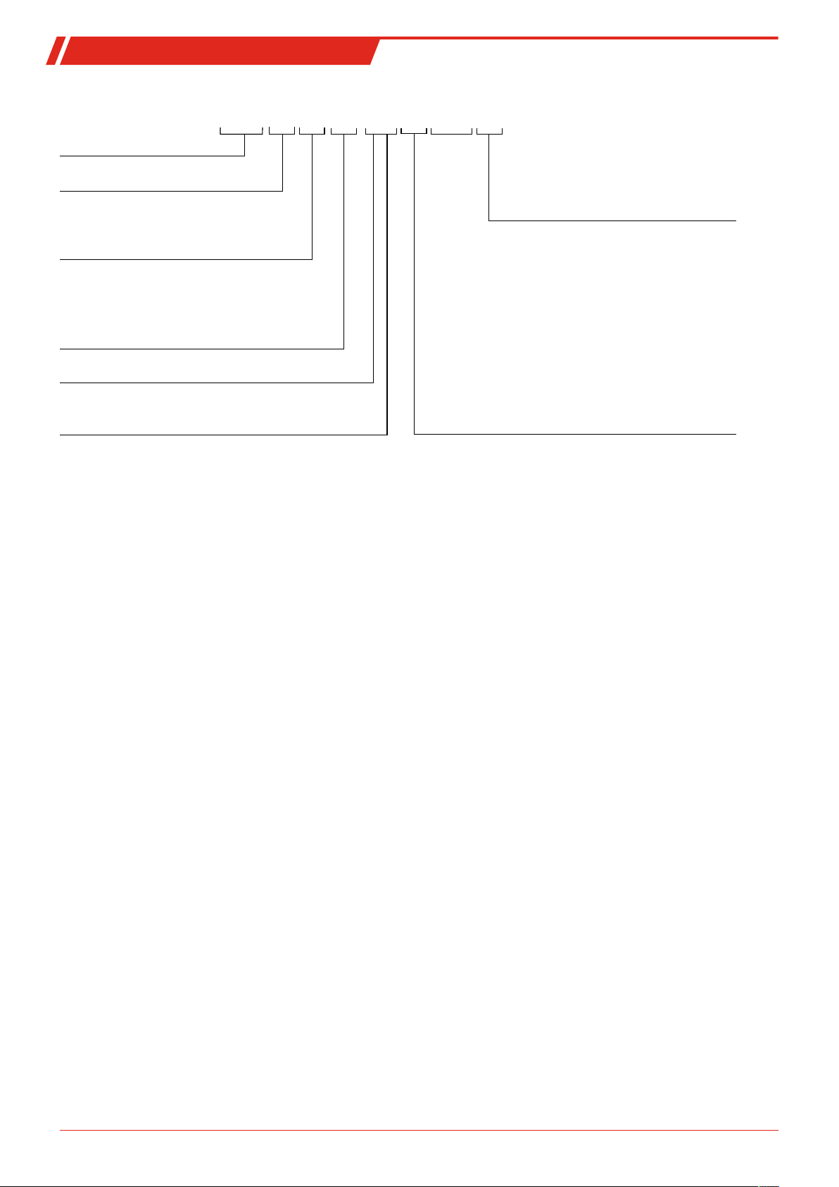
Type designation
Version
Z0
Zone0
Plug connection
M3
M12
2M12
Length in mm (max. 1500)
280
370
500
variable (please specify)
Level measurement
1-4
Number of contacts
K
W
= NC/NO
= Change-over contact
Temperature
TK50NC
TK60NC
TK70NC
TK50NO
TK60NO
TK70NO
= 50 °C NC
= 60 °C NC
= 70 °C NC
Pt100
Temperature sensor
Stilling tube
SSR
NT 61
Level contact
Options
-
XX
XX
ATEX
XX
X X
= 50 °C NO
= 60 °C NO
= 70 °C NO
XX
XX
-
-
-
-
-
-
1.4 Model key
1.5 Scope of Delivery
– 1 x Level switch
– 1 x Rubberised cork seal D1=90 x D2=60x4, item no.: 9009113
– 6 x Hexagon screw, item no.: 9011606
– 6 x Disc DIN125-A5.3, item no.: 9012234
– Product documentation
3Bühler Technologies GmbHBE100028 ◦ 10/2017
Page 6
NT 61-Z0-Atex
DANGER
WARNING
CAUTION
NOTICE
2 Safety instructions
2.1 Important advice
This unit may only be used if:
– The product is being used under the conditions described in the operating- and system instructions, used according to the
nameplate and for applications for which it is intended. Any unauthorized modifications of the device will void the warranty
provided by Bühler Technologies GmbH,
– The specifications and markings in the type plate are observed,
– The specified limits are observed,
– The equipment is operated on intrinsically-safe circuits, see chapter “Intrinsically-Safe Connection”,
– The protective element is installed outside the explosive area,
– No equipment functions exceed the limits,
– Monitoring equipment / protection devices are connected correctly,
– Service and repair work not described in these instructions are performed by Bühler Technologies GmbH,
– Genuine replacement parts are used.
Regulations IEC/EN60079-14 and IEC/EN60079-17 must be observed when erecting electrical systems in explosive areas.
Additional national regulations pertaining to initial operation, operation, maintenance, repairs and disposal must be observed.
These operating instructions are a part of the equipment. The manufacturer reserves the right to change performance-, specification- or technical data without prior notice. Please keep these instructions for future reference.
Signal words for warnings
Signal word for an imminent danger with high risk, resulting in severe injuries or death if not avoided.
Signal word for a hazardous situation with medium risk, possibly resulting in severe injuries or death if not
avoided.
Signal word for a hazardous situation with low risk, resulting in damaged to the device or the property or
minor or medium injuries if not avoided.
Signal word for important information to the product.
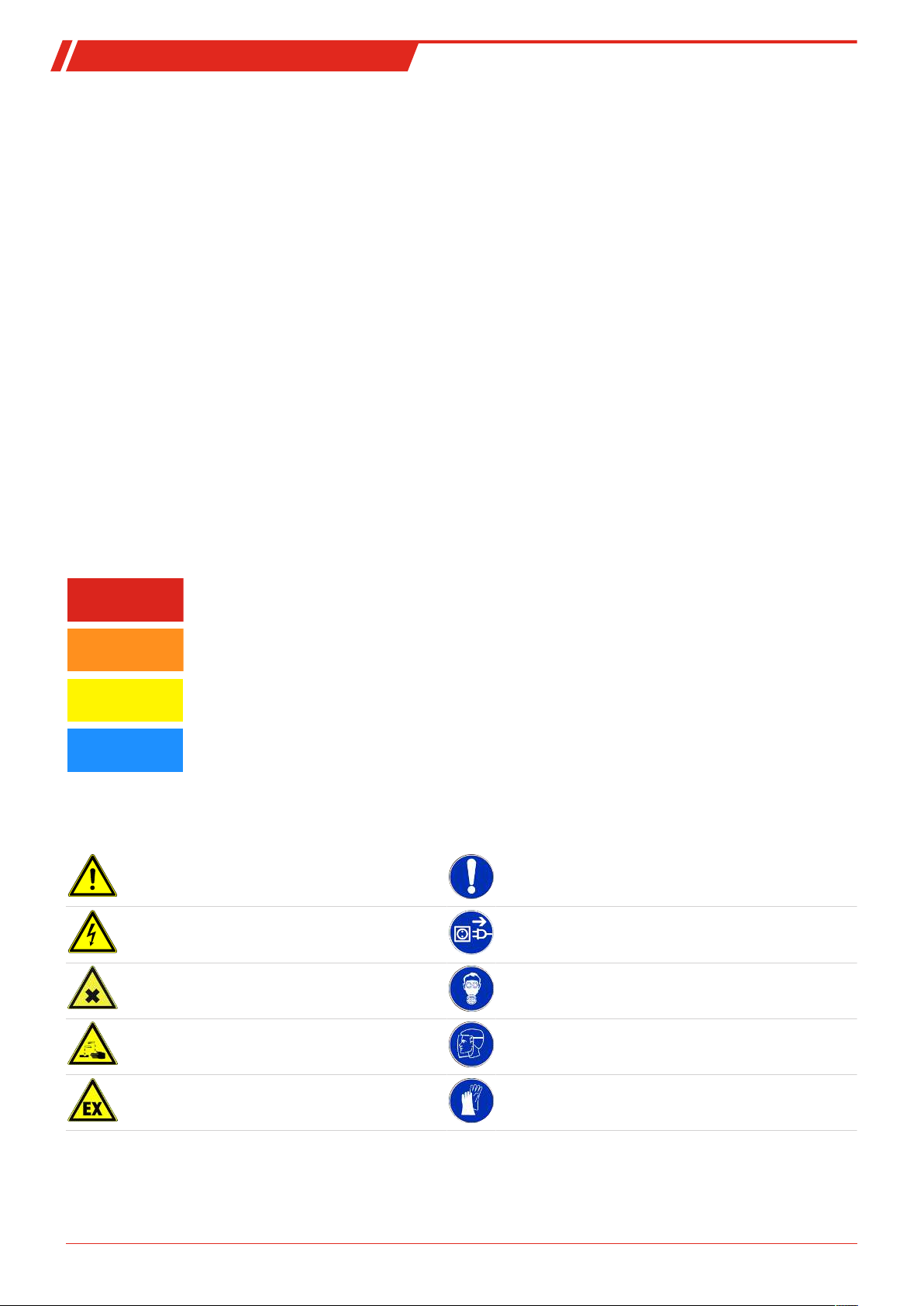
Warning signs
These instructions use the following warning signs:
Warns of a general hazard General information
Warns of voltage Unplug from mains
Warns not to inhale toxic gasses Wear respiratory equipment
Warns of corrosive liquids Wear a safety mask
Warns of explosive areas Wear gloves
4 Bühler Technologies GmbH BE100028 ◦ 10/2017
Page 7
NT 61-Z0-Atex
2.2 General hazard warnings
The equipment must be installed by a professional familiar with the safety requirements and risks.
Be sure to observe the safety regulations and generally applicable rules of technology relevant for the installation site. Prevent
malfunctions and avoid personal injuries and property damage.
The operator of the system must ensure:
– Safety notices and operating instructions are available and observed,
– The respective national accident prevention regulations are observed,
– The permissible data and operational conditions are maintained,
– Safety guards are used and mandatory maintenance is performed,
– Legal regulations are observed during disposal.
Maintenance, Repair
Please note during maintenance and repairs:
– Repairs to the unit must be performed by Bühler authorised personnel.
– Only perform conversion-, maintenance or installation work described in these operating and installation instructions.
– Always use genuine spare parts.
Always observe the applicable safety and operating regulations in the respective country of use when performing any type of
maintenance.
The method for cleaning the devices must be adapted to the IP protection class of the devices. Do not use cleaners which could
damage the device materials.
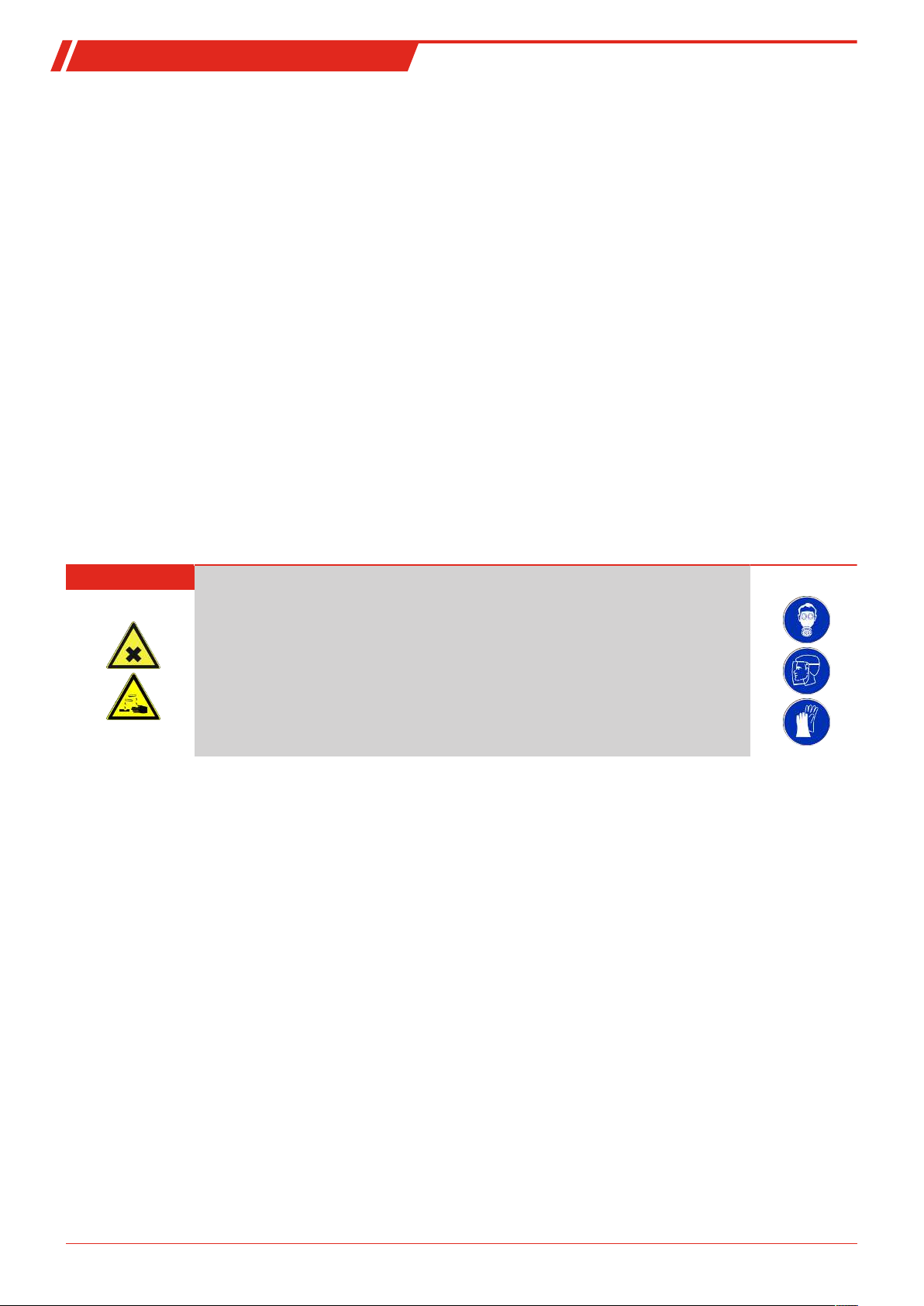
DANGER Toxic, acidic gases/liquids
Protect yourself from toxic, corrosive gasses/liquids when performing any type of work.
Wear appropriate protective equipment.
5Bühler Technologies GmbHBE100028 ◦ 10/2017
Page 8

NT 61-Z0-Atex
3 Transport and storage
Only transport the product inside the original packaging or a suitable alternative.
The equipment must be protected from moisture and heat when not in use. It must be stored in a covered, dry, dust-free room
at room temperature.
6 Bühler Technologies GmbH BE100028 ◦ 10/2017
Page 9
NT 61-Z0-Atex
4 Installation and connection
4.1 Installation
Please note before installing the level switch!
After transport and delivery of the level switch, the switching status of the bistable contacts may be different than required for
proper operation.
Therefore slide the float for the level switch along the level switch tube from below immediately before installation.
This ensures all built-in bistable contacts have a clearly defined switching status (NC or NO).
The level switch (transmitter) comes fully assembled and can be mounted to the tank by flange, included screws and seals.
Please be sure the float can move freely and to leave enough space between the tank wall and add-ons.
After removing the float, where applicable, be sure the magnet inside the float is above the fluid level. This can easily be verified
with a piece of iron to determine the magnet position inside the float.
4.2 Electrical connections
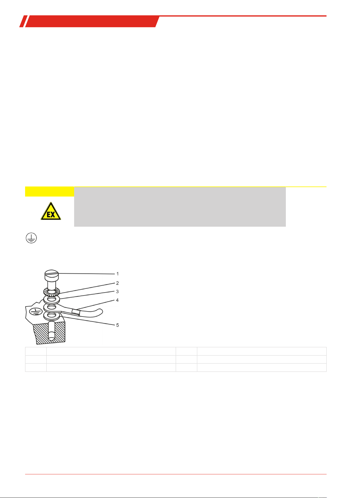
4.2.1 PA connection (potential equalisation)
CAUTION Electrostatic charge
Level switch housings and stilling tubes must be connected to the tank via external PA
connection!
Ensure the level switch is adequately earthed (minimum conductor cross-section 4mm2).
Particularly also observe the requirements of IEC/EN 60079-14.
The level switch has an external PA connection. This is identified by the decal shown on the left. The connection uses an
M5 thread. The PA cable for potential equalisation between the level switch or stilling tube (drawing B) and the tank is
not included with this version and must be supplied and installed by the customer.
Layout of the PA connection:
1 Screw 4 PA cable (to be installed by the customer)
2 Serrated washer 5 Washer
3 Washer
7Bühler Technologies GmbHBE100028 ◦ 10/2017
Page 10
NT 61-Z0-Atex
2
3
4
5
6
1
2
3
1
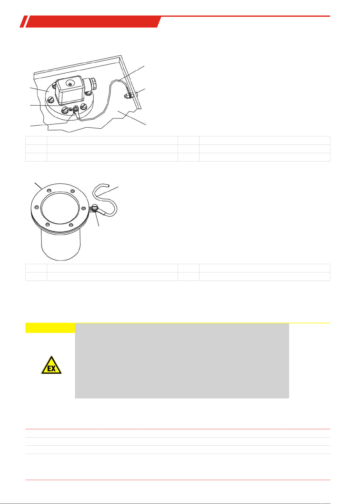
PA connection examples:
Drawing A
1 Level switch 4 PA cable
2 PA decals 5 PA connection on the tank
3 PA connection on the level switch 6 Tank
Drawing B
1 Stilling tube 3 PA connection
2 PA cable
4.2.2 Intrinsically-safe connection
According to IEC/EN60079-11 the components for level and temperature monitoring are simple electrical equipment and to be
considered purely ohmic circuits. They may only be operated with an type-tested controller with an intrinsically-safe circuit.
CAUTION Explosion hazard due to prohibited electrical connection data
Prohibited electrical connection data can cause an explosive gas mixture to ignite.
In areas with explosive gas atmospheres the level switch may only be operated with an
intrinsically-safe power supply. The power supply must be suitable for the respective
zone. The limits specified in these operating instructions must be observed and must not
exceeded, even with two separate intrinsically-safe power supplies.
Ensure the limits will not be exceeded, even in the event of a fault, e.g. accidental series
or parallel connection.
Please observe the relevant safety requirements, e.g. IEC/EN 60079-11 and IEC/EN
60079-14, when installing and operating intrinsically-safe equipment.
Please refer to the chart below for the technical parameters and the approved limits (Ui, Ii, Ci, L
tion:
Level contact 30V 50mA negligible negligible 100 mW
U
i
I
i
C
i
Temperature contact 30V 50mA negligible negligible 100 mW
Pt100 Temperature Sensor 30V 50mA negligible negligible 100 mW
) for intrinsically-safe opera-
i, Pi
L
i
P
i
8 Bühler Technologies GmbH BE100028 ◦ 10/2017
Page 11

NT 61-Z0-Atex
Remarks about the Pt100 connection
Operate the Pt100 with the respective EX approved RTD converter or a separating barrier with RTD input, suitable for EX. The
Measuring current must be
≤1mA
to prevent excessive self-heating, which will cause measuring errors.
9Bühler Technologies GmbHBE100028 ◦ 10/2017
Page 12

NT 61-Z0-Atex
5 Operation and control
DANGER Toxic, acidic gases/liquids
Protect yourself from toxic, corrosive gasses/liquids when performing any type of work.
Wear appropriate protective equipment.
DANGER Dangerous electrostatic charge (explosion hazard)
The equipment may only be used where normal operating conditions do not produce
frequent flammable, electrostatic discharge.
Sparking
Incendive electrostatic charges may occur when cleaning plastic housing parts and
decals (e.g. with a dry cloth or compressed air). The sparks this produces could ignite
flammable, explosive atmospheres.
Always clean plastic housing parts and decals
with a damp cloth
!
DANGER Impact
Strong blows to the housing can produce sparks, which can ignite an EX atmosphere.
Protect the equipment from external impact. Damaged housing parts must be replaced
immediately.
CAUTION Explosion hazard due to prohibited electrical connection data
Prohibited electrical connection data can cause an explosive gas mixture to ignite.
In areas with explosive gas atmospheres the level switch may only be operated with an
intrinsically-safe power supply. The power supply must be suitable for the respective
zone. The limits specified in these operating instructions must be observed and must not
exceeded, even with two separate intrinsically-safe power supplies.
Ensure the limits will not be exceeded, even in the event of a fault, e.g. accidental series
or parallel connection.
Please observe the relevant safety requirements, e.g. IEC/EN 60079-11 and IEC/EN
60079-14, when installing and operating intrinsically-safe equipment.
NOTICE
The device must not be operated beyond its specifications.
Before startup, check
– The electrical connections are undamaged and correctly installed.
– The level switch is connected intrinsically-safe (proof of intrinsic safety e.g. according to IEC/EN 60079-14),
– No parts have been removed from the level switches,
– Protection and monitoring devices are installed and functional (e.g. switch amplifier),
– The ambient parameters and technical specifications (e.g. Ui, Ii) are met,
– Electrical connections are securely connected and the monitoring devices are connected and set as prescribed.
– Precautions have been taken,
– The connectors are closed and the cable glands are properly sealed.
– The requirements of IEC/EN 60079-14 are met,
– The earth is proper and functional.
10 Bühler Technologies GmbH BE100028 ◦ 10/2017
Page 13

NT 61-Z0-Atex
Level display:
Inside the float of a level switch is a magnet which is mounted in a way that exceeding the level contacts (bistable reed contacts)
will trigger these magnetically. This can switch signals used to display the fill level.
Please note the technical specifications for the level switch and the connection diagrams at the end of this manual.
11Bühler Technologies GmbHBE100028 ◦ 10/2017
Page 14

NT 61-Z0-Atex
6 Cleaning and Maintenance
This device is maintenance-free.
The method for cleaning the devices must be adapted to the IP protection class of the devices. Do not use cleaners which could
damage the device materials.
12 Bühler Technologies GmbH BE100028 ◦ 10/2017
Page 15

NT 61-Z0-Atex
7 Service and repair
This chapter contains information on troubleshooting and correction should an error occur during operation.
Repairs to the unit must be performed by Bühler authorised personnel.
Please contact our Service Department with any questions:
Tel.: +49-(0)2102-498955
If the equipment is not functioning properly after correcting any malfunctions and switching on the power, it must be inspected
by the manufacturer. Please send the equipment inside suitable packaging to:
Bühler Technologies GmbH
- Reparatur/Service -
Harkortstraße 29
40880 Ratingen
Germany
Please also attached the completed and signed RMA decontamination statement to the packaging. We will otherwise be unable
to process your repair order.
You will find the form in the appendix of these instructions, or simply request it by e-mail:
service@buehler-technologies.com
or your agent
.
7.1 Spare parts and accessories
Item no. Description
9144 05 0010 Connecting cable M12x1, 4-pin, 1.5 m, angular coupling and straight plug
9144 05 0046 Connecting cable M12x1, 4-pin, 3.0 m, angular coupling and straight plug
9144 05 0047 Connecting cable M12x1, 4-pin, 5.0 m, angular coupling and strands
13Bühler Technologies GmbHBE100028 ◦ 10/2017
Page 16

NT 61-Z0-Atex
8 Disposal
Dispose of parts so as not to endanger the health or environment. Follow the laws in the country of use for disposing of electronic components and devices during disposal.
14 Bühler Technologies GmbH BE100028 ◦ 10/2017
Page 17
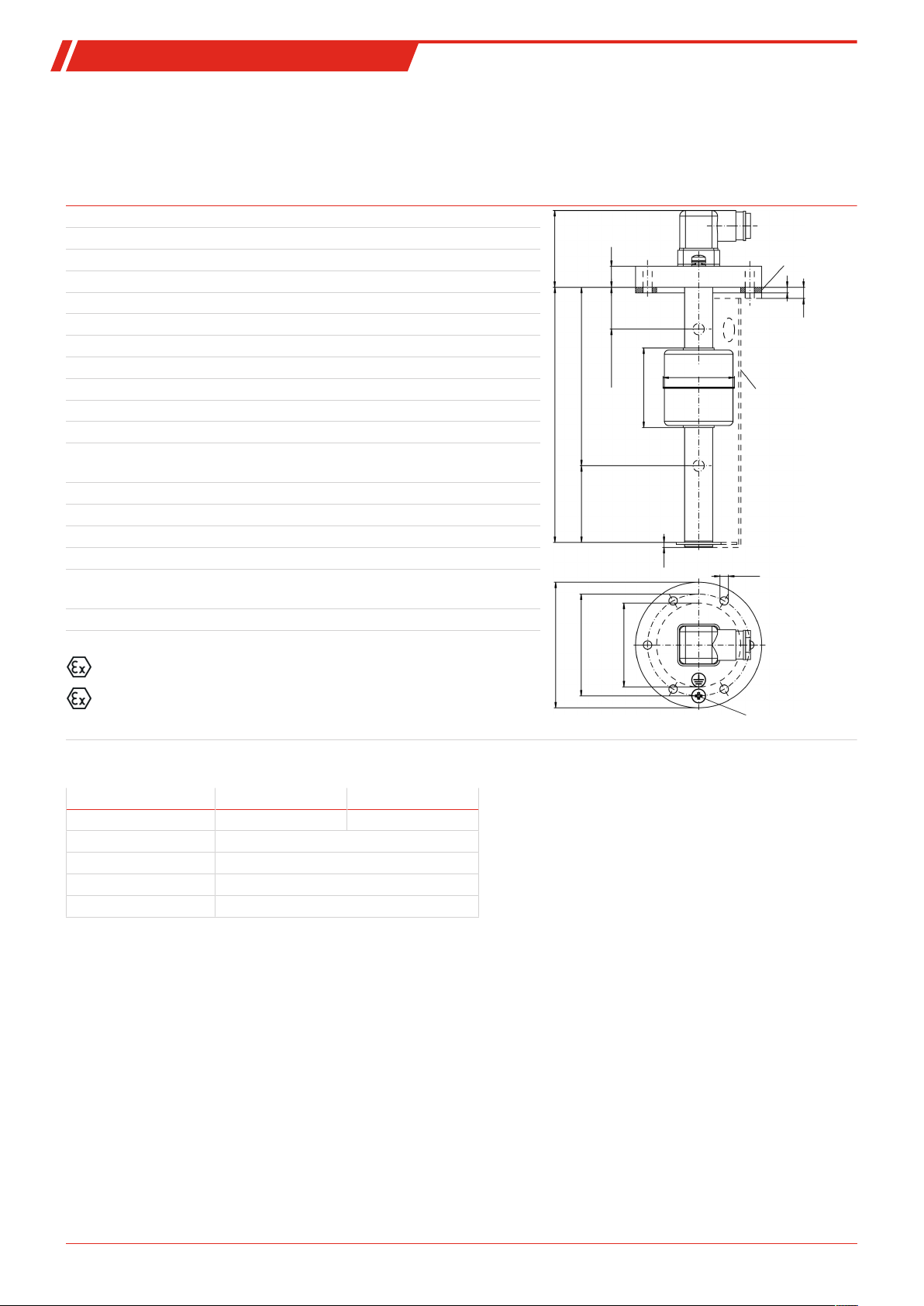
NT 61-Z0-Atex
55
15
L1 = min. 30
L2 = min. 70
L = max. 1500
min. 55 ***
Ø90
Ø73
Installation
dimensions
Ø60 *
Rubberised cork seal
first contact
PA connection
M5
*min. Ø61 with ATEX stilling tube
**optional
ATEX
stilling tube (with
separate PA
connection M5)
incl. additional
NBR seal
57
4
8**
Ø51
last contact
**min. 80 with
temperature
measurement
3.5
6xØ6
9 Appendices
9.1 Technical Data
NT 61-Z0-Atex Dimensions
Operating pressure: max. 1 bar
Operating temperature: -20 °C to +70 °C
Ambient temperature: -20 °C to +70 °C
Min. fluid density: 0.85 kg/dm³
Weight at L = 280 mm: approx. 950 g
Each 100 mm add: approx. 50 g
Material
Float: 1.4571
Immersion tube: 1.4571
Flange (DIN 24557) 1.4571
Includes
Mounting screws (quantity 6) and rubberised cork seal.
Options
Stilling tube (SSR) 1.4571/NBR
The equipment comply with:
IEC60079-0 (Ed.6.0); IEC60079-11 (Ed.6.0);
EN60079-0:2012+A11:2013; EN60079-11:2012
ATEX/IECEx marking
II 1G Ex ia IIC T4 Ga
II 1D Ex ia IIIC T70°C Da
The level switches may only be operated on intrinsically-safe circuits!
Level switching outputs
Level contact K10 W11
Function NC/NO* Change-over contact
U
i
l
i
Li; C
i
P
i
*NC = rising NC contact/falling NO contact, NO = rising NO contact/falling NC contact
30 V
50 mA
Negligible
100 mW
15Bühler Technologies GmbHBE100028 ◦ 10/2017
Page 18

NT 61-Z0-Atex
Optional temperature switching outputs
Temperature contact TKÖ TKS
Function NC** NO**
U
i
l
i
Li; C
i
P
i
**NC = NC contact, NO = NO contact
Temperature signal
Pt100 Resistance Thermometer
Temperature sensor Pt100 Class B, DIN EN 60 751
Tolerance: ±0.8°K
P
i
U
i
l
i
l
(measuring current) ≤1 mA
Mess
Li; C
i
100 mW
30 V
50 mA
Negligible
30 V
50 mA
Negligible
100 mW
Pt100 measuring resistance base values
°C 0 10 20 30 40 50 60 70 80 90 100
Ohm 100.00 103.90 107.79 111.67 115.54 119.40 123.24 127.07 130.89 134.70 138.50
16 Bühler Technologies GmbH BE100028 ◦ 10/2017
Page 19
NT 61-Z0-Atex
A
B
3
12
PE
9.2 Standard pin assignment
Plug connection
M3 M12 2 x M12
Dimensions
Number of pins 3-pin + PE 4-pin 4-pin / 4-pin
DIN EN 175301-803 61076-2-101 61076-2-101
Degree of protection IP65 IP67** IP67**
Cable fitting PG 11
** with respective plug top
Connection schematic
Only level contact(s)
type K10 (NC/NO)
Only level contact(s)
type W11
(changeover contact)
Level contact(s)
type K10
plus temperature contact TK
M3 M12
(base)
1 x K… 2 x K… 1 x K… 2 x K…
2 x M12
(base)
Level contact(s)
type K10
plus Pt100 temperature
sensor
Level contact(s)
type W11
plus temperature contact TK
Level contact(s)
type W11
plus Pt100 temperature
sensor
17Bühler Technologies GmbHBE100028 ◦ 10/2017
Page 20
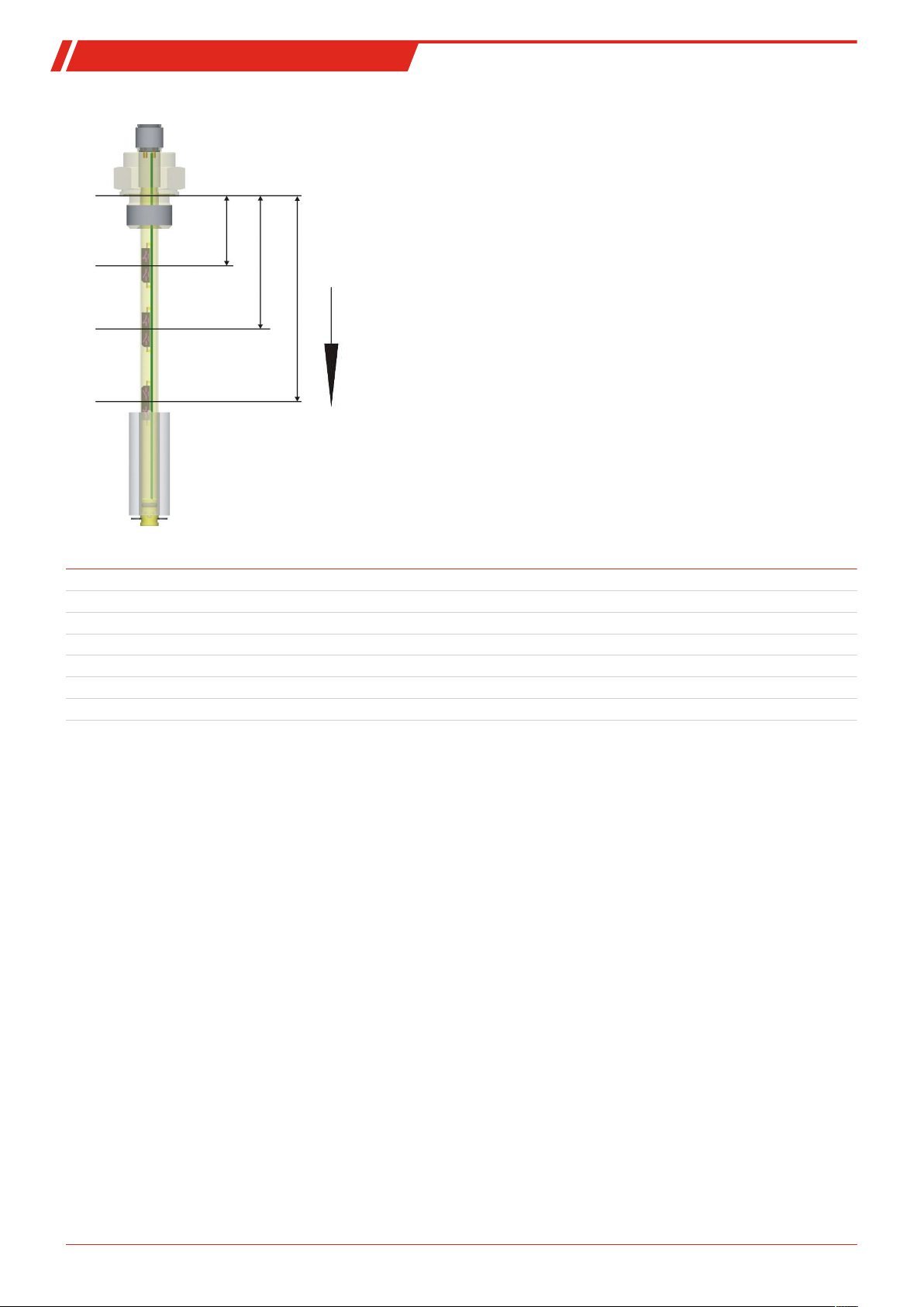
NT 61-Z0-Atex
L1
L2
L3
L1 = Contact no. 1
L2 = Contact no. 2
L3 = Contact no. 3
, etc.
The contact positions are measured top to bottom:
Note: The number of contacts may be limited depending on the level
switch model (see model key in the type plate and technical data).
9.3 Definitions
Abbreviation Explanation
NO rising NO contact/falling NC contact
NC rising NC contact/falling NO contact
TK Temperature contact
PT Pt100 Temperature Sensor
SSR Stilling tube
L1, L2, L3, L4 Level contact
T1, T2, T3, T4 Temperature output / contact
Information about temperature contacts:
Depending on the version ordered, the temperature contacts (TK) may be a temperature contact as NO contact (TKS), temperature contact as NC contact (TKÖ) or a Pt100 temperature sensor.
18 Bühler Technologies GmbH BE100028 ◦ 10/2017
Page 21

NT 61-Z0-Atex
10 Attached documents
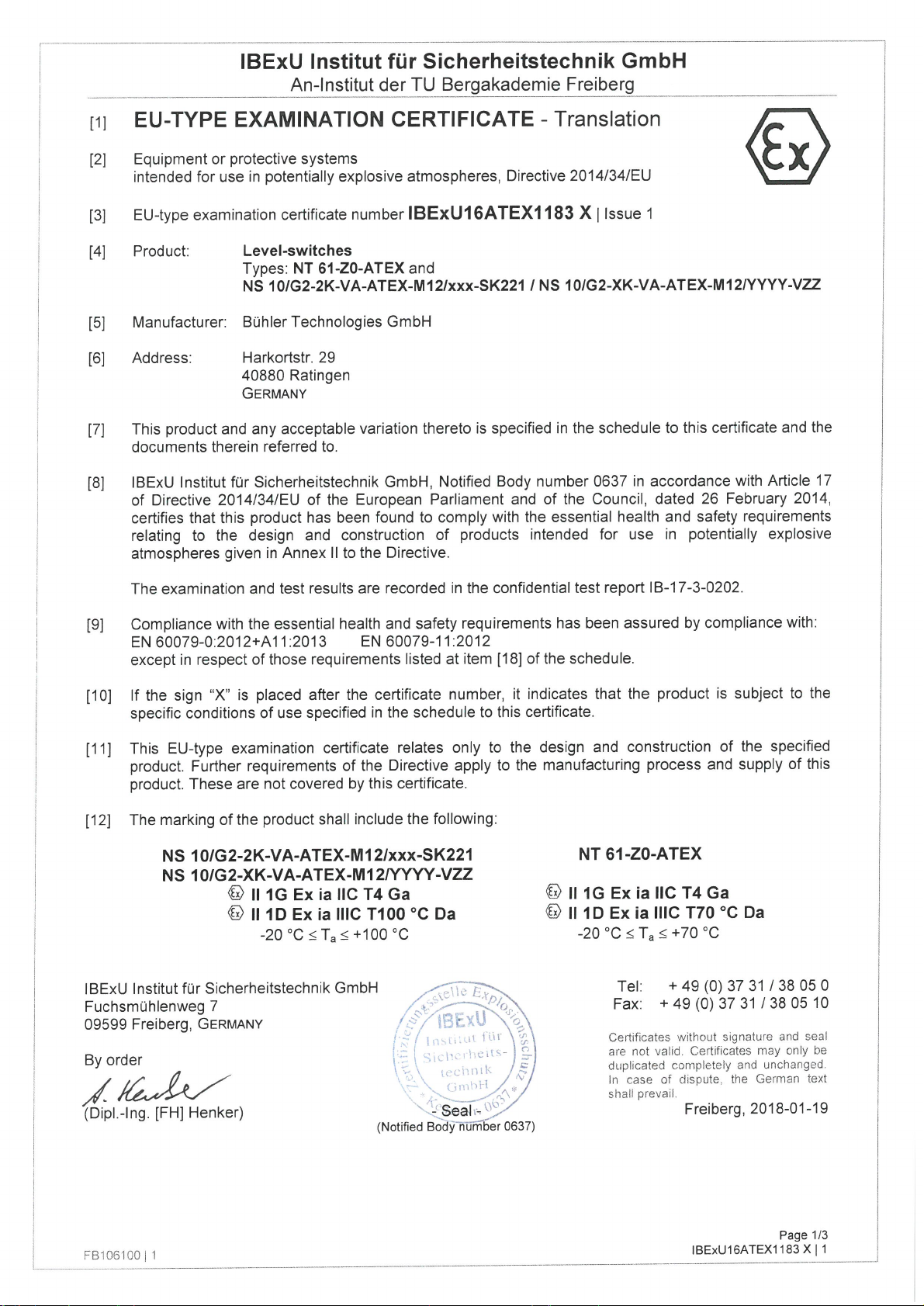
– EU-Type Examination Certificate IBExU16ATEX1183X
– Declaration of Conformity KX100032
– RMA - Decontamination Statement
19Bühler Technologies GmbHBE100028 ◦ 10/2017
Page 22
Page 23
Page 24

Page 25
Page 26

Page 27

Page 28

Page 29

Page 30

Page 31

Page 32
 Loading...