

Page 1
Page 2
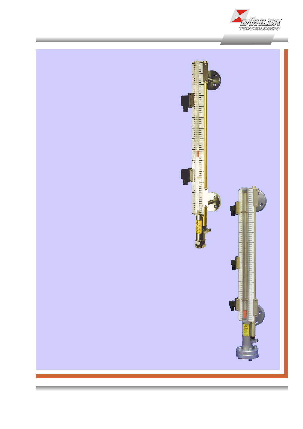
Technical data NS 10 ..-AM
Basic unit
max. operating pressure 10 bar
max. operating temperature 100 °C
min. spec. density of fluid 0.75 kg/dm³
Material
float SK166 NBR
standpipe 1.4571
flange steel galvanized
sight glass PC
sealing cap 1.4571
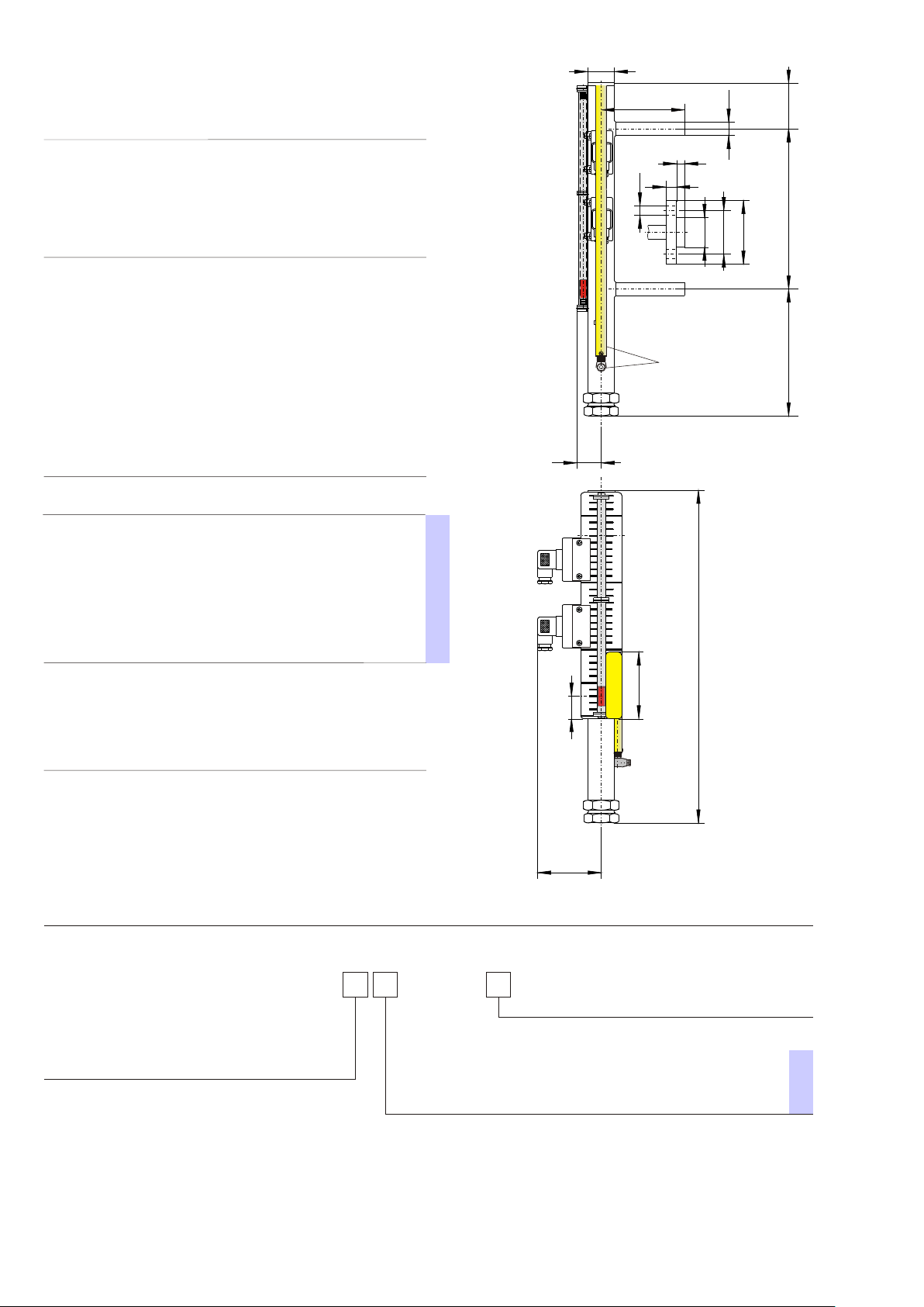
Design 0-AM 15-AM 25-AM
connector pipe flange flange
flange DIN 2656 DN15 DN25
øD 20 95 115
øk 65 85
ød 14 14
b 16 18
øA 45 68
h 12 14
weight at L1=500 mm, approx. 7.5 kg 8 kg 8.75 kg
weight L1 + 100 mm, approx. 0.2 kg 0.2 kg 0.2 kg
Other designs on request
appropriate level contacts see on page 4
Ø40
125
Ø D
65
h
b
Ød
ØA
ØD
Øk
F00000075X
optional transducer
tube with continuous
output signal
37
L1 = max. 2700
190
Option
transducer tube -K continuous level
measurement principle reed contact
resolution 5 or 10 mm
operating voltage (U ) 10 - 30 V DC
B
output 4 - 20 mA
(nominal voltage 24 V DC)
load W max. = (U - 7.5 V) / 0.02 A
B
O
P
T
I
O
N
Accessories:
Part No.
22 51 000 flange gasket 45/22x2 mm (DN15)
22 52 000 flange gasket 68/27x2 mm (DN25)
22 71 999 mounting bolts 8 x M12x65
Notes on the Pressure Equipment Directive:
The level switches were designed, manufactured and tested in
accordance with the Pressure Equipment Directive 91/23/EU and the
AD 2000 Code.
The category actually achieved by the level sensor is printed on the
type plate. Depending on this category, comprehensive quality
assurance is performed according to Module H and/or H1 standard.
Product code for NS 10
L=(L1+258)
100
No contacts here
Pas de contacts ici
Hier keine Kontakte
34
96
-SK166/NS 10/
Design
Length
L1 = ...mm
0-AM with stub pipe
15-AM flange DN 15
25-AM flange DN 25
Option transducer tube
-K5 continuous resolution 5 mm
-K10 continuous resolution 10 mm
Example for order
You need: Level switch for the external mounting, operating pressure max. 10 bar, with flange connection DN15,
distance of stub L1 = 1500 mm, with 2 change over contacts MKS - 1/W
You order: NS 10/15-AM-SK166 / 1500
2 x Part No. 288 99 99 contact MKS 1/W
DE 20 0201
02/2012
Page 2/4
we reserve the right to amend specifications
O
P
T.
Page 3

Technical data NS 25 ..-AM
Basic unit
max. operating pressure 25 bar
max. operating temperature 120 °C
min. spec. density of fluid SK 661 SK 662
0.85 kg/dm³ 0.70 kg/dm³
Material
float 1.4571
standpipe 1.4571
flange galvanized steel
sight glass PC
Design 15-AM 25-AM
connector flange flange
flange DIN 2656 DN15 DN25
øD 95 115
øk 65 85
ød 14 14
b 16 18
øA 45 68
h 12 14
S with float SK 661 205 205
SK 662 390 390
weight at L1 = 500 mm, approx 9.5 kg 10.5 kg
weight L1+100 mm, approx. 0.4 kg 0.4 kg
other designs on request
125
b
d
ø
5X
2
01
0
F0
h
k
ø
øD
øA
optional transducer
tube with continuous
output signal
86
appropriate level contacts see on page 4
Option
transducer tube -K continuous level
measurement principle reed contact
resolution 5 or 10 mm
operating voltage(U ) 10 - 30 V DC
B
output 4 - 20 mA
(nominal voltage 24 V DC)
load W max. = (U - 7.5 V) / 0.02 A
B
O
P
T
I
O
N
L1
8
6
+
+S
1
L
L=
Accessories
Part No. Description
22 51 000 flange gasket 45/22x2mm (DN15)
22 52 000 flange gasket 68/27x2mm (DN25)
22 71 999 mounting bolts 8 x M12x65
Notes on the Pressure Equipment Directive:
S
The level switches were designed, manufactured and tested in accordance
with the Pressure Equipment Directive 91/23/EU and the AD 2000 Code.
The category actually achieved by the level sensor is printed on the type plate.
Depending on this category, comprehensive quality assurance is performed
according to Module H and/or H1 standard.
ø115
Product code for NS 25
NS 25/
Design
15-AM flange DN 15
25-AM flange DN 25
O
Option transducer tube
-K5 continuous resolution 5 mm
P
-K10 continuous resolution 10 mm
T.
Example for order
You need: Level switch for external mounting, operating pressure max. 25 bar, with flange connector DN25,
You order: NS 25/25-AM-K10-SK661 / 1500
DE 20 0201
02/2012
Page 3/4
spec. density of fluid 0.89 kg/dm³ stub distance L1 = 1500mm, continuous level output, resolution 10 mm and
with 2 change over contacts MKS - 1/W (see on page 4)
2 x Part No. 288 99 99 contact MKS - 1/W
/
Length
L1 = ...mm
float type
-SK661 min. spec. density of fluid 0.85 kg/dm³
-SK662 min. spec. density of fluid 0.70 kg/dm³
We reserve the right to amend specifications
Page 4

Contacts for NS ..-AM
Type MKS-1/K
function NC / NO
max. voltage 230 V AC/DC
max. current 1 A
max. load of contact 50 VA
connector DIN EN 175301-803 (M3)
3 pol. + PE
protection system IP 65
Part No. 28 88 999
Pin assignment (contact position empty reservoir)
mounting left mounting right
1
2
3
PE
1
2
3
PE
Type MKS-2/K
function 2 x NC / NO
max. voltage 230 V AC/DC
max. current 1 A
max. load of contact 50 VA
connector S6
6 pol. + PE
protection system IP 65
Part No. 28 91 999
Type MKS-1/W
function change over
max. voltage 230 V AC/DC
max. current 1 A
max. load of contact 50 VA
connector DIN EN 175301-803 (M3)
3 pol. + PE
protection system IP 65
Part No. 28 89 999
Type MKS-1/W-L 24 V
function change over with LED
max. voltage 24 V DC
max. current 1 A
max. load of contact 25 VA
connector S6
6 pol. + PE
protection system IP 65
Part No. 28 90 999
1
2
3
4
5
6
PE
1
2
3
PE
1 +24V
2
3
4 GND
LED red LED red
5
6
PE
1
2
3
4
5
6
PE
1
2
3
PE
1 +24V
2
3
4 GND
5
6
PE
other contacts on request
For operations in areas with strong vibrations we
suggest to use contacts MKS-1/K and MKS-2K.
Pin assignment for AM-K with connector S3
MKS 1/K
MKS 1/W
65
79
3
4
65
3
4
MKS 2/K
81
4-20
mA
1 +24V DC
level out
2
When mounting a
transducer tube
with continuous output
signals you have to
keep in mind that the
mounting of contacts
is possible only
on the left side.
MKS 1/W-L24V
56
81
34
DE 20 0201
02/2012
Page 4/4
We reserve the right to amend specifications
 Loading...