

Page 1
FluidControl
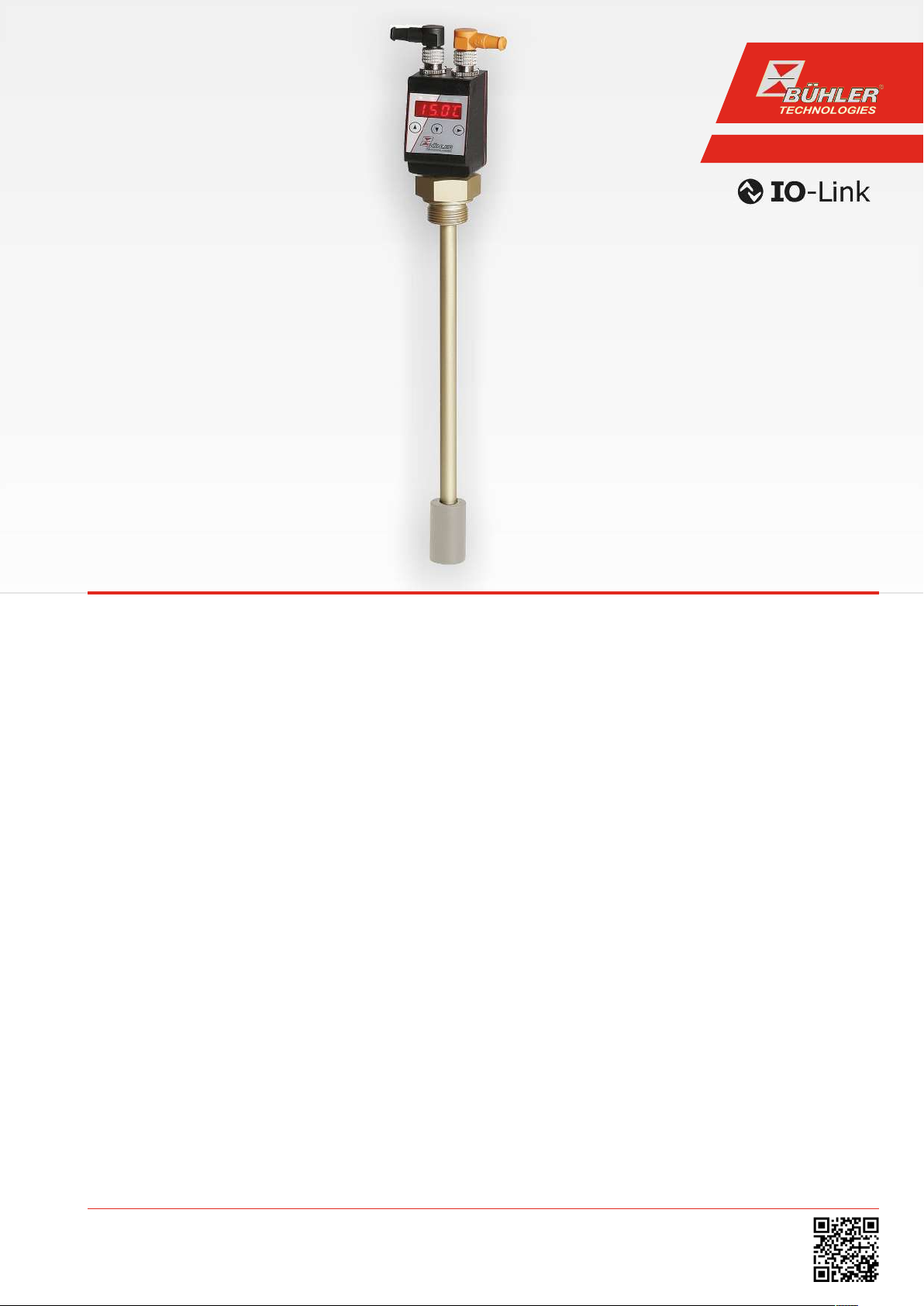
Level- and temperature sensor
Nivotemp NT M-XP
Installation and Operation Instructions
Original instructions
BE100023
05/2017
Bühler Technologies GmbH, Harkortstr. 29, D-40880 Ratingen
Tel. +49 (0) 21 02 / 49 89-0, Fax: +49 (0) 21 02 / 49 89-20
E-Mail: fluidcontrol@buehler-technologies.com
Internet: www.buehler-technologies.com
Page 2

Bühler Technologies GmbH, Harkortstr. 29, D-40880 Ratingen
Tel. +49 (0) 21 02 / 49 89-0, Fax: +49 (0) 21 02 / 49 89-20
Internet: www.buehler-technologies.com
E-Mail: fluidcontrol@buehler-technologies.com
Read this instruction carefully prior to installation and/or use. Pay attention particularly to all advises and safety instructions to prevent injuries. Bühler Technologies can not be held responsible for misusing
the product or unreliable function due to unauthorised modifications.
All rights reserved. Bühler Technologies GmbH 2017
Document information
Document No.......................................................... BE100023
Version..........................................................................05/2017
Page 3

Nivotemp NT M-XP
Contents
1 Introduction..................................................................................................................................................................................................................... 3
1.1 Intended Use......................................................................................................................................................................................................... 3
1.2 Functionality......................................................................................................................................................................................................... 3
1.2.1 Fill level monitoring.............................................................................................................................................................................3
1.2.2 Temperature monitor .........................................................................................................................................................................3
1.3 Design types.......................................................................................................................................................................................................... 3
1.4 Model key...............................................................................................................................................................................................................4
1.5 Scope of Delivery.................................................................................................................................................................................................. 4
2 Safety instructions......................................................................................................................................................................................................... 5
2.1 Important advice................................................................................................................................................................................................. 5
2.2 General hazard warnings .................................................................................................................................................................................6
3 Transport and storage .................................................................................................................................................................................................. 7
4 Setup and connection...................................................................................................................................................................................................8
4.1 Installation............................................................................................................................................................................................................8
4.2 Electrical connections ........................................................................................................................................................................................8
5 Operation and control ..................................................................................................................................................................................................9
5.1 Start-up procedure .............................................................................................................................................................................................9
5.2 LED statuses ..........................................................................................................................................................................................................9
5.3 General key functions ......................................................................................................................................................................................10
5.4 Keylock enabled ................................................................................................................................................................................................. 10
5.5 Menu overview ...................................................................................................................................................................................................11
5.6 Changing basic settings .................................................................................................................................................................................. 12
5.6.1 Set fill level unit .................................................................................................................................................................................. 12
5.6.2 Set temperature unit......................................................................................................................................................................... 12
5.6.3 Reallocate switching outputs ......................................................................................................................................................... 13
5.6.4 Set display refresh rate .....................................................................................................................................................................13
5.6.5 Enable/disable keylock......................................................................................................................................................................14
5.6.6 Fill level scaling....................................................................................................................................................................................14
5.6.7 Assigning the upper limit of the sensor measuring range.................................................................................................... 15
5.6.8 Sensor measuring range lower limit assignment ....................................................................................................................15
5.6.9 Restore factory settings (Reset)...................................................................................................................................................... 15
5.7 Switching outputs..............................................................................................................................................................................................17
5.7.1 Switching output x: Definition of the switching characteristic........................................................................................... 17
5.7.2 Switching output x: Upper switching limit (switching point)..............................................................................................18
5.7.3 Switching output x: Lower switching limit (switch-back point) ..........................................................................................19
5.7.4 Switching output x: Switch-on delay ...........................................................................................................................................19
5.7.5 Switching output x: Switch-back delay .......................................................................................................................................19
5.7.6 Switching output x: Testing the switching output................................................................................................................. 20
5.7.7 Change status LED display function ............................................................................................................................................ 20
5.8 Analogue outputs ............................................................................................................................................................................................. 21
5.8.1 Analogue output x: Assigning the upper limit.......................................................................................................................... 21
5.8.2 Analogue output x: Lower limit assignment ............................................................................................................................ 22
5.8.3 Analogue output x: Signal type assignment............................................................................................................................. 22
5.8.4 Analogue output x: Testing the analogue output ...................................................................................................................23
5.9 Diagnostic options ............................................................................................................................................................................................23
5.9.1 View logbook........................................................................................................................................................................................23
5.9.2 Maximum and minimum fill level ...............................................................................................................................................24
5.9.3 Maximum and minimum temperature ..................................................................................................................................... 24
5.9.4 Define switching output to log ......................................................................................................................................................25
5.9.5 Delay for storing the Min/Max Fill Level......................................................................................................................................25
5.9.6 Delay for storing the Min/Max Temperature ............................................................................................................................25
6 Cleaning and Maintenance.......................................................................................................................................................................................26
7 Service and repair......................................................................................................................................................................................................... 27
7.1 Troubleshooting ................................................................................................................................................................................................ 27
7.2 Spare parts and accessories ...........................................................................................................................................................................28
iBühler Technologies GmbHBE100023 ◦ 05/2017
Page 4

Nivotemp NT M-XP
8 Disposal...........................................................................................................................................................................................................................29
9 Appendices.....................................................................................................................................................................................................................30
9.1 Technical Data NT M-XP ..................................................................................................................................................................................30
9.2 Dimensions NT M-XP........................................................................................................................................................................................32
9.3 Standard pin assignment NT M-XP.............................................................................................................................................................. 32
9.4 Current settings................................................................................................................................................................................................. 33
9.5 Display ranges ....................................................................................................................................................................................................34
9.6 Display resolution.............................................................................................................................................................................................34
9.7 Menu Sequence Overview .............................................................................................................................................................................. 35
10 Attached documents...................................................................................................................................................................................................36
ii Bühler Technologies GmbH BE100023 ◦ 05/2017
Page 5

Nivotemp NT M-XP
1 Introduction
1.1 Intended Use
Level switches are used to monitor the fill level and temperature in fluid systems.
Level switches must not be used in highly flammable or corrosive liquids.
The medium must not contain particles, particularly metallic particles, to prevent deposits on the float or between the float and
switching tube. If necessary, filter the medium.
Please note the technical data in the appendix for the specific intended use, existing material combinations, as well as temperature limits.
WARNING
All device models are solely intended for industrial applications. They are
ponents
safety and health of persons.
Use in explosive areas is
. The devices must not be used if failure or malfunction thereof jeopardises the
1.2 Functionality
1.2.1 Fill level monitoring
prohibited
.
not safety com-
The measuring tube is located inside the tank. The reed-contact is located inside the measuring tube.
Simply put, the reed-contact works the same as a regular resistance potentiometer. The reed-contact consists of a number of
reed switches along with resistors connected in series. The total length of the chain varies by the path being monitored.
If a magnet inside a float trips the reed switch, a resistance signal proportional to the position of the float will be output. When
the float changes positions, resistances are more or less activated and the resistance signal altered based on the position of the
float. The resistance signal passes through a transformer yet and is analysed by the display unit.
1.2.2 Temperature monitor
Temperature is monitored via temperature sensor (Pt100) inside the sensor tube. Depending on the version, there are several
switching outputs combined with one analogue output (4 - 20mA). The temperature is shown in the display.
Please note the technical data in the appendix.
1.3 Design types
The level switch is equipped with different switching and analogue outputs based on the configuration. The outputs are freely
programmable.
The level switch can be equipped with the following options:
OV
G1
Please refer to the type plate for your equipment configuration. In addition to the job number, this also contains the item number and type designation.
Oval flange
Adapter to G1" flange
3Bühler Technologies GmbHBE100023 ◦ 05/2017
Page 6

Nivotemp NT M-XP
NT M-XP
M12 - 4-pin
2M12 - 4-pin
M12 - 8-pin
2M12 - 1 x 4-pin, 1 x 8-pin
BrassMS
Version
200
280
370
500
650
800
2 x PNP switching output
Output card
2S-KN-KT
2S
2 x PNP switching output
1 x analogue level output
1 x analogue temperature output
4 x PNP switching output
1 x analogue level output
1 x analogue temperature output
4S-KN-KT
Optional
OV
G1
Oval flange
Adapter to G1"
For 2S version only
For 4S-KN-KT and 6S version only
For 6S-KN-KT version only
Type designation with display, control unit
Plug connection
Length (max. 1400 mm)
4S
4 x PNP switching output
4 x PNP switching output
1 x analogue level output
1 x analogue temperature output
6 x PNP switching output
6S
6S-KN-KT
1)
2)
3)
1)
3)
2)
-
----
----
----
----
1 x IO-Link
1 x PNP switching output
1D1S
1.4 Model key
1.5 Scope of Delivery
– Level switch
– Product documentation
– Connection/mounting accessories (optional)
4 Bühler Technologies GmbH BE100023 ◦ 05/2017
Page 7
Nivotemp NT M-XP
DANGER
WARNING
CAUTION
NOTICE
2 Safety instructions
2.1 Important advice
Operation of the device is only valid if:
– the product is used under the conditions described in the installation- and operation instruction, the intended application
according to the type plate and the intended use. In case of unauthorized modifications done by the user Bühler Technologies GmbH can not be held responsible for any damage,
– when complying with the specifications and markings on the nameplates.
– the performance limits given in the datasheets and in the installation- and operation instruction are obeyed,
– monitoring devices and safety devices are installed properly,
– service and repair is carried out by Bühler Technologies GmbH,
– only original spare parts are used.
This manual is part of the equipment. The manufacturer keeps the right to modify specifications without advanced notice. Keep
this manual for later use.
Signal words for warnings
Signal word for an imminent danger with high risk, resulting in severe injuries or death if not avoided.
Signal word for a hazardous situation with medium risk, possibly resulting in severe injuries or death if not
avoided.
Signal word for a hazardous situation with low risk, resulting in damaged to the device or the property or
minor or medium injuries if not avoided.
Signal word for important information to the product.
Warning signs
These instructions use the following warning signs:
Warns of a general hazard Unplug from mains
Voltage warning Wear respiratory equipment
Warns not to inhale toxic gasses Wear a safety mask
Warns of corrosive liquids Wear gloves
General information
5Bühler Technologies GmbHBE100023 ◦ 05/2017
Page 8
Nivotemp NT M-XP
2.2 General hazard warnings
The equipment must be installed by a professional familiar with the safety requirements and risks.
Be sure to observe the safety regulations and generally applicable rules of technology relevant for the installation site. Prevent
malfunctions and avoid personal injuries and property damage.
The operator of the system must ensure:
– Safety notices and operating instructions are available and observed,
– The respective national accident prevention regulations are observed,
– The permissible data and operational conditions are maintained,
– Safety guards are used and mandatory maintenance is performed,
– Legal regulations are observed during disposal.
Maintenance, Repair
Please note during maintenance and repairs:
– Repairs to the unit must be performed by Bühler authorised personnel.
– Only perform conversion-, maintenance or installation work described in these operating and installation instructions.
– Always use genuine spare parts.
Always observe the applicable safety and operating regulations in the respective country of use when performing any type of
maintenance.
The method for cleaning the devices must be adapted to the IP protection class of the devices. Do not use cleaners which could
damage the device materials.
DANGER Toxic, acidic gases/liquids
Protect yourself from toxic, corrosive gasses/liquids when performing any type of work.
Wear appropriate protective equipment.
6 Bühler Technologies GmbH BE100023 ◦ 05/2017
Page 9

Nivotemp NT M-XP
3 Transport and storage
Only transport the product inside the original packaging or a suitable alternative.
The equipment must be protected from moisture and heat when not in use. It must be stored in a covered, dry, dust-free room
at room temperature.
7Bühler Technologies GmbHBE100023 ◦ 05/2017
Page 10
Nivotemp NT M-XP
Supply voltage
4 Setup and connection
DANGER Electric voltage
Risk of electric shock
a) Always disconnect the unit from the mains before performing work.
b) Secure the equipment from accidental restarting.
c) The equipment may only be installed, maintained and put into operation by instruc-
ted, competent personnel.
d) Always observe the applicable safety regulations for the operating site.
DANGER Toxic, acidic gases/liquids
Protect yourself from toxic, corrosive gasses/liquids when performing any type of work.
Wear appropriate protective equipment.
4.1 Installation
The level switch comes fully assembled and can be mounted to the tank using the screw-in thread. Please be sure the float can
move freely and to leave enough space between the tank wall and add-ons.
After removing the float, where applicable, be sure the magnet inside the float is above the fluid level. This can easily be verified
with a piece of iron to determine the magnet position inside the float.
DANGER Electric voltage
Risk of electric shock
When connecting devices, please note the maximum voltages and currents currents (see
technical data) and use the correct wire cross-sections and circuit breakers.
When selecting the connection lines, also note the maximum operating temperatures of
the devices.
Installation in special areas of application:
If the device will be installed outdoors or in wet areas, the maximum operating voltage
is max. 16 V DC effective or 35 V DC.
The flange-mounted display units can be swivelled vertically by approx. 270° so they are easier to read. Please note the built-in
swivel stop. You will notice more resistance when reaching the stop. Turning it beyond this stop may damage the display unit.
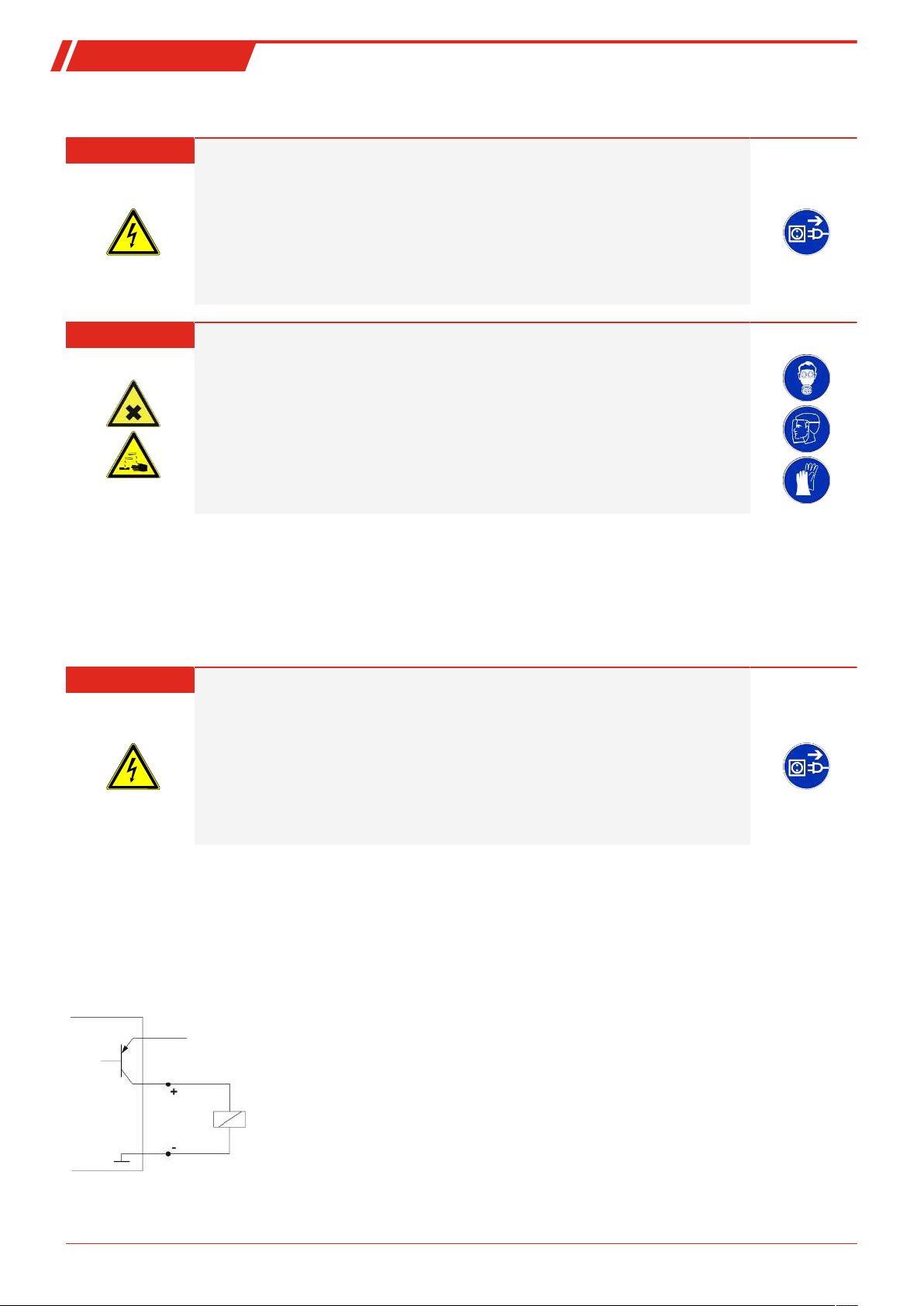
4.2 Electrical connections
Electricity is supplied via plug connectors. Please refer to the appendix for installation dimensions, nominal voltage and plug
configuration.
The temperature switching outputs are PNP transistors (see illustration):
Note:
When measuring the switching output with high-load measuring device inputs or when used as a frequency output, the
load must be set to 10 kΩ between the output and earth (GND) to avoid faulty measurements.
8 Bühler Technologies GmbH BE100023 ◦ 05/2017
Page 11
Nivotemp NT M-XP
LEDs
Control keys
Display
5 Operation and control
NOTICE
The device must not be operated beyond its specifications.
5.1 Start-up procedure
The device will automatically switch on when connected to power. It will first briefly display the software version, at which time
the device will also check the built-in components. The display will then switch to displaying measurements.
The following describes the function of the display and control unit:
If an error message appears in the display during operation, please refer to the
and Repair”.
Troubleshooting
table under chapter “Service
5.2 LED statuses
LEDs above the measurement display indicate the status of the switching outputs. The LEDs are permanently assigned to the
switching outputs.
The following table lists the factory settings for the fill level and temperature switching output configuration:
LED 1 – yellow
Status switching output 1
LED 2 - red
Status switching output 2
LED 3 – yellow
Status switching output 3
LED 4 – red
Status switching output 4
LED 5 – yellow
Status switching output 5
2 Switching
outputs
Fill Level Fill Level Fill Level
Temperature Fill Level Fill Level
--- Temperature Fill Level
--- Temperature Temperature
--- --- Temperature
4 Switching
outputs
6 Switching
outputs
The switching characteristics of the LED (on if switching contact closed or open) can be changed.
LED 6 – red
Status switching output 6
--- --- Temperature
9Bühler Technologies GmbHBE100023 ◦ 05/2017
Page 12
Nivotemp NT M-XP
5.3 General key functions
The keys below the display are used for operation.
The menu controls are detailed in the following chapters.
Key Mode Function
– Measurement display: Change measured variables displayed.
– In the menu: Move down one menu level.
Move up one menu level.
– At the end of the menu:
The display indicates the end of the menu.
– Following input/selection: Confirm and save a numerical value entered or a function selection. The dis-
play will flash if a parameter has been changed.
– Measurement display: Displays the configuration.
– In the menu: Scroll up menu item, numerical value or function selection. Holding the key
will continuously scroll.
– Measurement display: Go to main menu.
– In the menu: Scroll down menu item, numerical value or function selection. Holding the key
will continuously scroll.
+
+
60 s no action – In the menu: Exit the main / sub/ drop-down menu.
– In the menu: Exit the main / sub / drop-down menu and return to displaying the measure-
ment without saving changes to the parameters.
– In the menu: Move to the next higher menu level.
To select a menu item and to enter values:
– Open the main menu with the key.
– Select the submenu with the and keys and open the submenu with the key.
– If necessary, select the next submenu with the and keys and open with the key.
– Select the desired menu item with the and keys and open the list of values with the key.
– Set the value with the and keys and confirm with the key. The new settings will the saved and the device will return
to the submenu.
– Select the menu item EXIT to exit the submenu and confirm with the key. The device will return to the next menu level up
or to the measurement display.
5.4 Keylock enabled
With the keylock enabled, selecting the menu with the key will display in place of the main menu. The active
digit will be indicated by a dot.
– Use the and keys to enter the code and confirm with the key. The active digit will move one place to the right. After
entering the 3rd digit the main menu will open.
If the wrong code is entered, the device will return to the measurement display. If you forgot the password you can always enter
master code 287 to access the menu.
You can cancel the keylock under Loc in submenu
Basic Settings Advanced Options
b.EF and enter 000 to reset the code.
10 Bühler Technologies GmbH BE100023 ◦ 05/2017
Page 13
Nivotemp NT M-XP
Configuration
Equipment configuration
o___i
____
oiI
Display
Measurement display
Level
Fill Level main menu
out1
Settings menu OUT1
Out 1
out_
Settings menu OUTX
Out X
An 1
Settings menu Analog 1
Analog Out 1
E
Exit menu level
Exit
out_
Settings menu OUTX
Out X
out_
Settings menu OUTX
Out X
An 2
Settings menu Analog 2
Analog Out 2
E
Exit menu level
Exit
tEMP
Temperature main menu
Temperature
b.EF
Basic Adv. Functions
Basic EF
If applicable
If applicable
If applicable
If applicable
If applicable
DiA
Diagnostics menu
Diagnostic
E
Exit menu level
Exit
____
____
Toggle display
Toggle
5.5 Menu overview
The menu structure is based on the VDMA standard sheet 24574-1. The menu structure is hierarchic. The top menu level contains
the main menu items, e.g. oil, tEMP, b.EF, diA, E. Each main menu contains additional submenu items.
The menu items may vary depending on the device configuration. Not all menu items described below will necessarily apply to
your device. Press the key in display mode to open the configuration. A 4-digit code will appear, e.g.
With the 4 digits tsav meaning:
t: Model
s: Number of switching outputs
a: Number of analogue outputs
v: Device installation type
o = level and temperature measurement
2, 4 or 6
0 for 2
i = standard installation (tank installation)
The individual menu items will not be shown if the option does not apply. Example: With a=0 the menu items for configuring
the analogue output does not apply. You can then skip the description for this item.
The structure of main menu
the analogue outputs (if applicable).
Fill Level
(oil) and
temperature
(tEMP) is identical. Here you can configure the switching outputs or
11Bühler Technologies GmbHBE100023 ◦ 05/2017
Page 14

Nivotemp NT M-XP
Basic EF
b.EF
Basic Adv. Functions
o.uni
Fill Level unit
Set Unit Level
___
-I - - non
Selection menu
Basic EF
b.EF
Basic Adv. Functions
t.uni
Temperature unit
Set Unit Temp
;_
;C - ;F
Selection menu
The basic device settings can be changed. General settings can be configured under
These settings should be configured first, as they affect the displays and settings for the individual menus. These settings are
e.g. the units used and allocating switching outputs for fill level and temperature measurement. The allocation of the analogue
outputs cannot be changed.
Diagnostic
The
For the detailed illustration of the entire menu structure please refer to the original operating instructions at the end of this
chapter.
(dia) menu further contains diagnostics options.
Basic Settings Advanced Functions
(b.EF).
5.6 Changing basic settings
The general basic settings can be changed under menu
measurement display and the configuration options in the various main menus. This is also where the allocation of switching
outputs can be changed.
– Press the key to open the main menu.
– Here, select menu item (bEF) using the and keys and open the menu with the key.
Basic Settings Advanced Functions
(bEF). These settings will affect the
5.6.1 Set fill level unit
Used to set the unit symbol for the fill level:
The options are:
Options:
[-1-, cn, in, Lit, CAL, non]
Percent cm inch
Note:
– When non "no unit" is selected, the display will scale measurements to a four-digit output.
– Measurements are not automatically converted. After switching the unit (if necessary), the
measuring range should be scaled (see menu
5.6.2 Set temperature unit
This is where the unit symbol for the temperature is configured:
The options are:
Degrees
Celsius
Note:
– Values are automatically converted and the measuring range adjusted. However, always check
the respective switching points and switch-back points.
Fill Level
Litre
o.Hi and o.Lo).
Gallons
Degrees
Fahrenheit
none
12 Bühler Technologies GmbH BE100023 ◦ 05/2017
Page 15

Nivotemp NT M-XP
Basic EF
b.EF
Basic Adv. Functions
r.ou_
Assignment Out X
reassign OX
____
oil - tEMP
Selection menu
Basic EF
b.EF
Basic Adv. Functions
Di5
Display rate
Display Rate
____
FASt - oFF
Selection menu
5.6.3 Reallocate switching outputs
This describes how to change the allocation of switching outputs for switching output1. This procedure also applies to all other
switching outputs.
Switching outputs 1 to n can be freely allocated to the measured variable fill level or temperature. The allocation affects the appearance of the
Example: OUT 1 is to be allocated to the temperature. In this case, r.ou1 must be set to tEMP. This will switch the settings menu
out1 from
NOTICE Reallocate switching outputs
fill level
Fill Level
oil and
menu to the
When reallocating the switching outputs always check all the related settings! The previous values will not automatically be adjusted! It does not affect allocation of the status
display LEDs.
temperature
Temperature
The options are:
Level measurement Temperature measurement
tEMP menus. The factory setting allocates switching output OUT1 to the fill level.
menu. The procedure for changing the settings does not change.
Use the same procedure as for switching output 1 to allocate the other switching outputs for measuring the fill level or temperature.
– Use the same steps specified for switching output OUT1.
5.6.4 Set display refresh rate
The refresh rate of the display can be changed based on the application. The display can also be completely disabled. The LEDs
will remain functional.
The options are:
fast medium slow Display off
Note:
– Error messages will still appear, even with the display off.
13Bühler Technologies GmbHBE100023 ◦ 05/2017
Page 16

Nivotemp NT M-XP
Basic EF
b.EF
Basic Adv. Functions
Lock
Locks the keys
Lock Device
___
0 - 999
Selection menu
5.6.5 Enable/disable keylock
The keylock can be enabled to prevent unauthorised changes to the device settings.
The keylock will be enabled after entering at least one digit > 0. A dot indicates the active digit during this input.
– Use the key to open the list of values:
Setting range:
000 to 999
– Enter the digit using the and keys (0 to 9) and press the key to confirm. The active digit
will move one place to the right.
– Lastly, press the key to confirm the code.
The device will now return to the submenu.
Note:
– To disable the keylock enter: 000
5.6.6 Fill level scaling
The display range is scaled between the highest and lowest float position. This scaling will also affect the display accuracy and
the resolution for determining the switching outputs for the fill level.
The following illustration shows the factory setting for the switching outputs and the display:
A = factory settings
1 = measuring range
Models with analogue output:
The factory setting for the display is in descending order for increasing fill level, so the bottom position shows 0% and the top
position shows 100%. The values can be switched as described below.
14 Bühler Technologies GmbH BE100023 ◦ 05/2017
Page 17

Nivotemp NT M-XP
Basic EF
b.EF
Basic Adv. Functions
o.Hi
Assign 100 %
Set Upper
____
-999 - 9999
Selection menu
Basic EF
b.EF
Basic Adv. Functions
o.Lo
Assign 0 %
Set Lower
____
-999 - 9999
Selection menu
Basic EF
b.EF
Basic Adv. Functions
rES
Factory setting
Reset
___
no - YES
Confirm
5.6.7 Assigning the upper limit of the sensor measuring range
This determines the display value (upper limit for the measuring range) for the maximum fill level:
Assigns the maximum display value (upper limit of the measuring range) to the maximum fill level.
Note:
Setting range:
-999…9999
– For the add-on sensor the display range is preset to 0-100%.
5.6.8 Sensor measuring range lower limit assignment
This determines the display value (lower limit of the measuring range) for the minimum fill level:
Assigns the smallest display value (lower limit of the measuring range) to the minimum fill level.
Note:
Setting range:
-999…9999
– For the add-on sensor the display range is preset to 0-100%.
5.6.9 Restore factory settings (Reset)
Use the Reset function (rES) to restore the factory settings. All changes will be lost. Since this will also reset the limits, you must
check the fill level and temperature settings.
The options are:
Original status:
No,
keep current settings
The factory settings are:
Definitions:
SP x / rPx Switching point / switch-back point x
ds x / drx Switch-on delay / switch-back delay for switching output x
A x ..Hi / Ax.Lo Maximum and minimum measurement for output
A.ou x Analogue output signal type
ou x Switching characteristic for switching output x
o.uni / t.uni Unit for fill level / temperature
o.Hi / o.Lo maximum / minimum fill level
r.ou x Switching output x fill level or temperature monitoring allocation
dis Display refresh rate
Loc Keylock
SJ.ou switching output logged
do.MM Delay for recording the minimum / maximum fill level
dt.MM Delay for recording the minimum / maximum temperature
Note:
For customer-specific specifications the factory preset may vary from those listed here.
Original status:
Yes,
reset settings to the factory defaults.
15Bühler Technologies GmbHBE100023 ◦ 05/2017
Page 18

Nivotemp NT M-XP
Version with 2 switching outputs:
Switching outputs Basic Settings
SP1 / rP1 5% / 2% o.uni -I- (%)
ds1 / dr1 / ou1 0 / 0 / Hno t.uni °C
SP2 / rP2 60 / 55°C o.Hi 100 %
ds2 / dr2 / ou2 0 / 0 / Hno o.Lo 0 %
Version with 4 switching outputs:
Switching outputs Basic Settings
SP1 / rP1 5% / 2% o.uni -I- (%)
ds1 / dr1 / ou1 0 / 0 / Hno t.uni °C
SP2 / rP2 15% / 12% o.Hi 100 %
ds2 / dr2 / ou2 0 / 0 / Hno o.Lo 0 %
SP3 / rP3 70 / 65 °C r.ou1 oiL
ds3 / dr3 / ou3 0 / 0 / Hno r.ou2 oiL
SP4 / rP4 80 / 75°C r.ou3 tEMP
ds4 / dr4 / ou4 0 / 0 / Hno r.ou4 tEMP
r.ou1 oiL
r.ou2 tEMP
dis FASt
Loc 000
dis FASt
Loc 000
Version with 6 switching outputs:
Switching outputs Basic Settings
SP1 / rP1 5% / 2% o.uni -I- (%)
ds1 / dr1 / ou1 0 / 0 / Hno t.uni °C
SP2 / rP2 15% / 12% o.Hi 100 %
ds2 / dr2 / ou2 0 / 0 / Hno o.Lo 0 %
SP3 / rP3 70% / 65% r.ou1 oiL
ds3 / dr3 / ou3 0 / 0 / Hno r.ou2 oiL
SP4 / rP4 80 / 75°C r.ou3 oiL
ds4 / dr4 / ou4 0 / 0 / Hno r.ou4 tEMP
SP5 / rP5 80 / 75°C r.ou5 tEMP
ds5 / dr5 / ou5 0 / 0 / Hno r.ou6 tEMP
SP6 / rP6 80 / 75°C dis FASt
ds6 / dr6 / ou6 0 / 0 / Hno Loc 000
Version with analogue outputs:
Analogue outputs
A1.Hi / A1.Lo / A.ou1 0 / 100 / i1
A2.Hi / A2.Lo / A.ou2 0 / 100 / i1
Diagnostic settings:
Diagnostics
SJ.ou out1
dh.MM 0.0
dt.MM 0.0
16 Bühler Technologies GmbH BE100023 ◦ 05/2017
Page 19

Nivotemp NT M-XP
Display
____
Measurement display
____
Measured variable main menu
Measured variable
out_
Out X
Settings menu OUTX
Measured variable
____
out_
Measured variable main menu
Out X
EF_
EF X
Advanced Functions
ou_
Set Out X
Definition OUTX
___
Selection menu
Hno - FM
Settings menu OUTX
SP
rP
Hno
(NO contact)
Hnc
(NC contact)
Hysteresis
SP
-
rP
(
)
Time t
Time t
Time t
FH
FL
Fno
(NO contact)
Fnc
(NC contact)
Time t
Time t
Time t
Window
5.7 Switching outputs
All switching outputs are configured the same way. The switching output number is therefore represented by x. Open the
switching output to be configured from the menu for the respective measured variable.
The switching output allocation and other basic settings related to all switching outputs can be configured in menu
tings Advanced Functions
Use submenu
Advanced Functions
.
to configure additional settings for each individual switching output which e.g. affect the
switching characteristics of the output. The output can also be tested here.
5.7.1 Switching output x: Definition of the switching characteristic
The switching characteristic for the output can be configured under the following menu:
The options are:
Hysteresis Function
Hysteresis function
as the NO contact
Hysteresis function
as the NC contact
Window function
Window function as
NO contact
NO contact or NC contact function when the output
signal is set when exceeding the configured switching point. The output signal will be deleted if the
value is below the configured switch-back point.
Here, NO contact (Hno) means the PNP switching output is closed above switching point SPx and opens
below switching point rPx.
Here, NC contact (Hnc) means the PNP switching output is open above switching point SPx and closes below switching point rPx.
Also see the explanation in the drawing below.
NO contact or NC contact function defining a signal
window. When the measuring window is reached
the output signal is set and deleted upon exiting.
Here, NO contact (Fno) means the PNP switching output is closed if the value is within the window. Otherwise the switching output will be open.
Here, NC contact (Fnc) means the PNP switching output is open if the value is within the window. Otherwise the switching output will be closed.
Basic Set-
Window function as
NC contact
17Bühler Technologies GmbHBE100023 ◦ 05/2017
Page 20

Nivotemp NT M-XP
T ≤
corresponds
to f = 1 Hz
Time t
Time t
Time t
T = 47.5 °C
corresponds
to f = 50 Hz
T ≥
corresponds
to f = 100 Hz
F ILo
F IHi
Example:
= 15 °C,
= 80 °C
with temperature T and frequency f:
F ILo
F IHi
open
(0)
closed
(1)
open
(0)
closed
(1)
rising NO contact
falling NC contact
NO (normally open)
rising NC contact
falling NO contact
NC (normally closed)
Hno
Hnc
Note:
The designation of the switching function may vary:
Measured variable
Measured variable
____
out_
Measured variable main menu
Out X
____
SPI FHI F I.Hi
Switching point X
____
Selection menu
[ o.Lo - o.Hi ]
Settings menu OUTX
Frequency output
Frequency output
If the output is defined as a frequency output, a
square wave signal with a frequency between 1Hz
and 100Hz proportional to the measurement will be
output.
Note:
To increase the slew rate of the square wave
signal, we recommend loading the switching output
with an load of 10kΩ.
5.7.2 Switching output x: Upper switching limit (switching point)
The upper switching limit for switching output Out x can be defined with the following submenu:
Setting range:
[o.Lo]…[o.Hi]
18 Bühler Technologies GmbH BE100023 ◦ 05/2017
Switching point for OUT x
Note:
– The switching point must be set to within the range limits (see menu
– If switching output OUT x was assigned the function
– If switching output OUT x was assigned the function
Functions
).
setting corresponds with the upper window limit.
pear. The setting corresponds to the frequency 100 Hz.
Window
, will appear. The
Frequency output
Basic Settings Advanced
, will ap-
Page 21

Nivotemp NT M-XP
Measured variable
____
out_
Measured variable main menu
Out X
____
rPI FLI F I.Lo
Switch-back point X
____
Selection menu
[ o.Lo - o.Hi ]
Settings menu OUTX
Measured variable
____
out_
Measured variable main menu
Out X
EF_
EF X
Advanced Functions
dS_
Delay SP X
Delay OUTX On
___
Selection menu
0 - 100
Settings menu OUTX
Measured variable
____
out_
Measured variable main menu
Out X
EF_
EF X
Advanced Functions
dr_
Delay RP X
Delay OUTX Off
___
Selection menu
0 - 100
Settings menu OUTX
5.7.3 Switching output x: Lower switching limit (switch-back point)
The lower switching limit for switching output Out x can be defined with the following submenu:
Switch-back point for OUT x
Note:
Setting range:
[o.Lo]…[o.Hi]
– The switch-back point must be set to within the range limits.
– If switching output OUT x was assigned the function
Window
setting corresponds with the lower window limit.
, will appear. The
– If switching output OUT x was assigned the function
Frequency output
, will ap-
pear. The setting corresponds to the frequency 1Hz.
5.7.4 Switching output x: Switch-on delay
The menu
submenu level.
The switching and switch-back delay prevents the alarm being triggered too frequently in unstable conditions. The switching
delay can be configured with the following menu:
Setting range:
0…100 seconds
Advanced Functions
Time span in seconds during which the signal must be continuously present for the switching output to respond.
Note:
– If switching output OUTx was assigned the function
– If switching output OUT x was assigned the function
EFx is used to configure additional settings for switching output x. The submenu is at the second
Window
, the setting corresponds to the
switch-on delay which detects valid reaching of the measuring window.
Frequency output
, this value will have no
affect.
5.7.5 Switching output x: Switch-back delay
The switch-back delay can be configured with the following menu:
Setting range:
0…100 seconds
Switch-back signal delay for OUT x.
Time span in seconds during which the signal must be continuously present for the switching output to respond.
Note:
– If switching output OUTx was assigned the function
switch-on delay which detects valid closing of the measuring window.
– If switching output OUTx was assigned the function
affect.
Window
Frequency output
, the setting corresponds to the
, this value will have no
19Bühler Technologies GmbHBE100023 ◦ 05/2017
Page 22

Nivotemp NT M-XP
Measured variable
____
out_
Measured variable main menu
Out X
EF_
EF X
Advanced Functions
C.ou_
Check Out X
Functional test OUTX
____
Selection menu
n.oP - on
Settings menu OUTX
5.7.6 Switching output x: Testing the switching output
The switching output test can be started with the following menu:
Switching output test option
Options when setting ou1 to Hno / Hnc / Fno / Fnc:
Normal switching output opera-
tion
Switching output permanently
off disabled
Switching output permanently
activated
Options when setting ou1 to FM:
Normal mode as frequency out-
put
Output
Frequency 1 Hz
Output
Frequency 100 Hz
Note:
After completing the test, set the function to normal mode
–
n.oP
.
5.7.7 Change status LED display function
The LEDs in the display indicate the switching status of the output. The following table shows how LEDs are allocated to the
switching output:
Numbering
LED
Switching
output x
Assignment for
2 switching outputs
Assignment for
4 switching outputs
Assignment for
6 switching outputs
1 LED 1 - yellow LED 1 - yellow LED 1 - yellow
2 LED 2 - red LED 2 - red LED 2 - red
3 LED 3 - yellow LED 3 - yellow
4 LED 4 - red LED 4 - red
5 LED 5 - yellow
6 LED 6 - red
In the factory setting the LED indicates the physical status of the PNP switching output (switching output closed – LED on).
The logical indicator function may need to be different from the physical signal on the switching output. You can therefore also
reverse this indication with this menu (switching output open – LED on).
Example:
You have 2 switching outputs for the temperature, configured as:
Switching output 1:
–
temperature is higher than the desired range. So this LED lighting up indicates an “Error” status.
Switching output 2:
–
temperature. So in this case the LED would light up if the status is okay.
The table shows an example with the factory setting and with inverted status function for LED3. The switching points are
defined as:
SP3 = 70 °C, rP3 = 65 °C
SP4 = 80 °C, rP4 = 75 °C
20 Bühler Technologies GmbH BE100023 ◦ 05/2017
Max contact, rising NO contact. The LED lights up when exceeding the maximum temperature and the
Min contact, rising NO contact. So in the factory setting, the LED lights up when exceeding the minimum
Page 23

Nivotemp NT M-XP
LED3 ON
LED3 OFF
LED4 and LED3 ON
only LED4 ON
LED3 ON
LED 3 OFF
LED3 OFF
LED3 ON
Measured variable
____
out_
Measured variable main menu
Out X
EF_
EF X
Advanced Functions
LEd_
LED Out X
Function status LEDX
L=__
Selection menu
L= o - L=_o
Settings menu OUTX
Measured variable
____
An_
Measured variable main menu
Analog OutX
A I.Hi
Analog MaxX
Maximum value assignment
____
Selection menu
[ o.Lo - o.Hi ]
Settings menu Analog X
Factory setting Status function
State Status
LED 3 inverted
A
Temperature rises to > 70 °C
OK
PNP switching output 3 closed
B
Temperature rises to > 80 °C
Error
PNP switching output 4 closed
C
Temperature falls to < 75 °C
OK
PNP switching output 4 open
D
Temperature falls to < 65 °C
Error
PNP switching output 3 open
Here you can reverse the LED status function for a contact: the LED lights up if the contact is open, so below the minimum temperature, and the LED lighting up again indicates an “Error” status.
The options are:
LED = output;
the LED lights up when the PNP switching output
is closed.
the LED lights up when the PNP switching output
LED = -output;
is open.
NOTICE
The display function of the status LED affects event logging! Please note chapter “Diagnostic options”.
5.8 Analogue outputs
5.8.1 Analogue output x: Assigning the upper limit
Fill Level
Used to configure at which fill level to output the maximum analogue signal. This is configured in menu:
Setting range:
[o.Lo] … [o.Hi]
Note:
– The output range setting must not be less than 10 % of the measuring range: A I.Hi – A I.Lo >=
10% * (o.Hi – o.Lo)
– If the range is set too low, the analogue value output may have grades.
21Bühler Technologies GmbHBE100023 ◦ 05/2017
Page 24

Nivotemp NT M-XP
Measured variable
____
An_
Measured variable main menu
Analog OutX
A I.Hi
Analog MaxX
Maximum value assignment
____
Selection menu
[ o.Lo - o.Hi ]
Settings menu Analog X
Measured variable
____
An_
Measured variable main menu
Analog OutX
A I.Lo
Analog MinX
Minimum value assignment
____
Selection menu
[ o.Lo - o.Hi ]
Settings menu Analog X
Measured variable
____
An_
Measured variable main menu
Analog OutX
A I.Lo
Analog MinX
Minimum value assignment
____
Selection menu
[ o.Lo - o.Hi ]
Settings menu Analog X
Measured variable
____
An_
Measured variable main menu
Analog OutX
A.ou_
Set A.OUtX
Output function
_ _
Selection menu
i I - u 3
Settings menu Analog X
Temperature
Used to configure at which temperature to output the maximum analogue signal. This is configured in menu:
Note:
– The output range setting must not be less than 10 % of the measuring range: A I.Hi – A I.Lo >=
10%
Setting range:
0 °C to 100 °C
(32 °F to 212 °F)
– If the range is set too low, the analogue value output may have grades.
5.8.2 Analogue output x: Lower limit assignment
Fill Level
Used to configure at which fill level to output the minimum analogue signal. This is configured in menu:
Note:
– The output range setting must not be less than 10 % of the measuring range: A I.Hi – A I.Lo >=
10% * (o.Hi – o.Lo)
Setting range:
[o.Lo] … [o.Hi]
– If the range is set too low, the analogue value output may have grades.
Temperature
Used to configure at which temperature to output the minimum analogue signal. This is configured in menu:
Note:
– The output range setting must not be less than 10 % of the measuring range: A I.Hi – A I.Lo >=
10%
Setting range:
0 °C to 100 °C
(32 °F to 212 °F)
– If the range is set too low, the analogue value output may have grades.
5.8.3 Analogue output x: Signal type assignment
The analogue output can be defined as a voltage or current output with different value ranges. This is configured in menu:
22 Bühler Technologies GmbH BE100023 ◦ 05/2017
The options are:
4mA to 20mA
2V to 10V
0V to 10V
0V to 5V
Page 25

Nivotemp NT M-XP
Measured variable
____
An_
Measured variable main menu
Analog OutX
C.An_
Check AnX
Functional test Analog X
____
Selection menu
n.oP - Lo
Settings menu Analog X
Display
____
Measurement display
diA
Diagnostics menu
Diagnostic
Diagnostic
diA
Diagnostics menu
J.out
Log output
Journal Out
____
Jor I - ---
Selection menu
5.8.4 Analogue output x: Testing the analogue output
The analogue output can be tested. The highest, mean and lowest analogue value can be output successively. This is configured
in menu:
The options are:
Normal mode Highest analogue value output
Mean analogue value output Lowest analogue value output
Note:
After completing the test, set the function to normal mode
–
n.oP
.
5.9 Diagnostic options
The device is able to log events for a switching output. The LED lighting up is considered an event. The logging of switching procedures therefore depends on how the LED switching function is configured.
The configuration and analysis can be carried out here.
NOTICE
Only one switching output can be logged. The switching output to be logged is configured in menu item
– Press the key to open the main menu.
– Select menu item diA with the and keys.
From here you will be able to access various diagnostic values and measurement monitoring logs.
– Open the menu with the key.
You can now change or view the diagnostic settings.
Set Journal Out
(Sjou).
5.9.1 View logbook
The last 6 events for the switching output being logged can be viewed here and all entries deleted:
The journal entries will be displayed as:
– Most recent event Jor1 occurred x hours (h) / days (d) ago, Jor1 ⇔ 1.3h, key
– Events 2 to 5 occurred x hours / days ago,
– The oldest event Jor6 occurred x hours / days ago,
– Delete function (---)
*
not yet populated, only 4 events have occurred
Example:
Jor2 ⇔ 2.4h, key ,
Jor3 ⇔ 6.1h, key ,
Jor4 ⇔ 8.2h, key ,
Jor5 ⇔ non *, key ,
Jor6 ⇔ non *, key ,
---, key ; = delete
23Bühler Technologies GmbHBE100023 ◦ 05/2017
Page 26

Nivotemp NT M-XP
Diagnostic
diA
Diagnostics menu
o.MM
Max/Min Memory
Max/Min Level
____
____ - ---
Selection menu
Diagnostic
diA
Diagnostics menu
t.MM
Max/Min Memory
Max/Min Temp
____
____ - ---
Selection menu
The information displayed will alternate between the index and time for entry x, e.g. Jor1 ⇔ 1.4h
for the most recent event 1.4 hours ago.
Press the key to return to the submenu or use , to select the next journal entry.
Confirming the information with the key will delete the list of events and return
to the submenu.
Note:
– If no events have been logged, the display will alternate between Jorx and non.
5.9.2 Maximum and minimum fill level
Used to view or delete the saved maximum and minimum fill level:
The journal entries will be displayed as:
– Maximum fill level value, 150, key
– occurred x hours / days ago, 8.4h, key ,
– Minimum fill level value, 60, key ,
– occurred x hours / days ago, 2.1h, key ,
– Delete function
Press the key to return to the submenu or use , to select the next Journal entry.
Menu order:
Max. value,
min.
time Value
Time
delete
Confirming the information with the key will delete the list of events and return
to the submenu.
Example:
---, key ; = delete
5.9.3 Maximum and minimum temperature
Used to view or delete the saved maximum and minimum temperature:
The journal entries will be displayed as:
– Maximum temperature, 72°C, key
– occurred x hours / days ago, 8.4h, key ,
– Minimum temperature, 22°C, key ,
– occurred x hours / days ago, 2.1h, key ,
– Delete function
Menu order:
Max. value,
time
min. value
time
delete (reset)
24 Bühler Technologies GmbH BE100023 ◦ 05/2017
Example:
---, key ; = delete
Press the key to return to the submenu or use , to select the next Journal entry.
Confirming the information with the key will delete the list of events and return
to the submenu.
Page 27

Nivotemp NT M-XP
Diagnostic
diA
Diagnostics menu
SJ.ou
Output monitoring
Set Journal Out
out_
Out I - Out_
Selection menu
Diagnostic
diA
Diagnostics menu
do.MM
Min/Max Delay
Delay MM
___
0 - 100
Selection menu
Diagnostic
diA
Diagnostics menu
dt.MM
Min/Max Delay
Delay MM
___
0 - 100
Selection menu
5.9.4 Define switching output to log
Used to select the switching output to be logged. Only one switching output can be logged.
Switching output logging.
Options:
out1 to outx
NOTICE
Values are backed up from volatile to non-volatile memory approx. every three hours.
5.9.5 Delay for storing the Min/Max Fill Level
A delay time for saving the minimum and maximum fill level can be set to record reliable values when fluid levels are unstable.
Here, enter the time span in seconds during which the signal must be continuously present before the fill level is logged.
– Use the key to open the list of values.
– Set the value with the and keys and use the key to confirm (e.g. 5 (seconds).
Setting range:
0…100 seconds
The device will return to the submenu.
5.9.6 Delay for storing the Min/Max Temperature
A delay time for saving the minimum and maximum temperature can be set to record reliable values when temperatures fluctuate. Here, enter the time span in seconds during which the signal must be continuously present before the temperature is
logged.
– Use the key to open the list of values.
– Set the value with the and keys and use the key to confirm (e.g. 5 (seconds).
Setting range:
0…100 seconds
The device will return to the submenu.
25Bühler Technologies GmbHBE100023 ◦ 05/2017
Page 28

Nivotemp NT M-XP
6 Cleaning and Maintenance
This device is maintenance-free.
The method for cleaning the devices must be adapted to the IP protection class of the devices. Do not use cleaners which could
damage the device materials.
26 Bühler Technologies GmbH BE100023 ◦ 05/2017
Page 29

Nivotemp NT M-XP
7 Service and repair
This chapter contains information on troubleshooting and correction should an error occur during operation.
Repairs to the unit must be performed by Bühler authorised personnel.
Please contact our Service Department with any questions:
Tel.: +49-(0)2102-498955
If the equipment is not functioning properly after correcting any malfunctions and switching on the power, it must be inspected
by the manufacturer. Please send the equipment inside suitable packaging to:
Bühler Technologies GmbH
- Reparatur/Service -
Harkortstraße 29
40880 Ratingen
Germany
Please also attached the completed and signed RMA decontamination statement to the packaging. We will otherwise be unable
to process your repair order.
You will find the form in the appendix of these instructions, or simply request it by e-mail:
service@buehler-technologies.com
or your agent
.
7.1 Troubleshooting
Problem / Malfunction Possible cause Action
No display – No supply voltage – Check cable and replace, if necessary
Error messages on the display:
Alternating between Err and Exxx: e.g. ⇔
Error 001 – Ambient temperature too low – Maintain limits
Error 002 – Ambient temperature too high – Maintain limits
Error 004 – Pt100 defective (short-circuit) – Send device in for repair
Error 008 – Pt100 defective (cable break) – Send device in for repair
Error 016 – Defective reed-contact (short-circuit) – Send device in for repair
Error 032 – Defective reed-contact (supply line open) – Send device in for repair
Error 1024 – Second plug has no supply voltage – Check the supply voltage for the second
plug.
– Be sure to switch on or plug in the power
supply for the second plug before or shortly
after the first.
– Internal error – Please contact customer service
27Bühler Technologies GmbHBE100023 ◦ 05/2017
Page 30

Nivotemp NT M-XP
Possible errors
Problem / Malfunction Possible cause Action
Switching output not triggering when exceeding limits
Switching output constantly
switching
The analogue doesn’t receive
the full/correct output current
Analogue output doesn’t
change the output signal
when the input signal changes
– Switching output configured incorrectly – In submenu Coux: “Test Switching Output“ to
ensure normal mode
– Switching output defect – In submenu Coux: “Test Switching Output” to
test the desired switching output
– Switching output configured incorrectly – In submenu Coux: “Test Switching Output“ to
ensure normal mode
– Switching output defect – In submenu Coux: “Test Switching Output” to
test the desired switching output
– Wrong signal type set – In submenu Aoux: Check and if necessary set
the correct signal type (current/voltage out-
put)
– Load too high (current output) – Reduce load to permissible value
– Analogue output configured incorrectly – In submenu CAnx: „Test Analogue Output“ to
ensure normal mode
7.2 Spare parts and accessories
Accessories
Item no. 4-pin Item no. 8-pin Description
9144 05 0010 9144 05 0048 Connecting cable M12x1, 1.5 m, angular coupling and straight plug
9144 05 0046 9144 05 0049 Connecting cable M12x1, 3.0 m, angular coupling and straight plug
9144 05 0047 9144 05 0033 Connecting cable M12x1, 5.0 m, angular coupling and strands
28 Bühler Technologies GmbH BE100023 ◦ 05/2017
Page 31

Nivotemp NT M-XP
8 Disposal
Dispose of parts so as not to endanger the health or environment. Follow the laws in the country of use for disposing of electronic components and devices during disposal.
29Bühler Technologies GmbHBE100023 ◦ 05/2017
Page 32

Nivotemp NT M-XP
9 Appendices
9.1 Technical Data NT M-XP
Basic unit
Version MS
Operating pressure max. 1 bar
Operating temperature -20 °C to +80 °C
Float SK 171
Min. fluid density 0.80 kg/dm³
Lengths (all versions) 200, 280, 370, 500, 650, 820 mm
(other lengths available upon request)
Material / Version
Float PU
Immersion tube Brass
Flange (G3/4) Brass
Weight at L=280 mm
Each 150 mm add
Degree of protection IP65
approx. 390 g
approx. 20 g
Analysis Display Electronics
Display 4 character 7 segment LED
Operation Via 3 keys
Memory Min. / Max. Data memory
Starting current input approx. 100 mA for 100 ms
Current input during operation approx. 50 mA (without current- and switching outputs)
Supply voltage (UB) 10 - 30 V DC (nominal voltage 24 V DC) / with IO-Link 18 - 30 V DC
Ambient temperature -20 °C to +70°C
Display units Level Temperature
%, cm, L, i, Gal °C / °F
Display range adjustable -20 °C to +120 °C
Alarm setting range e.g. 0 – 100 % 0 °C to 100 °C
Display accuracy ± 1 % from end value ± 1 % from end value
Input values
Level Temperature
Principle of measurement Reed-contact
resolution 10 mm
Display units %, cm, L, i, Gal °C / °F
Pt100 Cl. B, DIN EN 60751
Tolerance ± 0.8 °C
30 Bühler Technologies GmbH BE100023 ◦ 05/2017
Page 33

Nivotemp NT M-XP
Optional switching outputs
1D1S 2S 4S 6S
Plug (base) 1 x M12 – 4-pin 1 x M12 – 4-pin 2 x M12 – 4-pin 1 x M12 – 8-pin
Switching outputs
Alarm memory with 1x assignable to
max. switching
current**
Contact load max. 1 A total max. 1 A total max. 1 A total max. 1 A total
*also programmable as frequency output.
**Output 1 max. 0,2 A.
Plug (base) 1 x M12 – 4-pin 1 x M12 – 8-pin 2 x M12 – 4-pin / 8-pin
Switching outputs
Alarm memory with 1x assignable to
max. switching current* 0.5 A per output
Contact load max. 1 A total max. 1 A total max. 1 A total
Analogue outputs
Programmable as 1 x 4 – 20 mA,
Max. burden Ω as
current output
Min. input load as
voltage output
IO-Link and 1 x freely
programmable with
selectable level or
temperature assignment
alarm logbook
0.5 A per output 0.5 A per output 0.5 A per output
2S-KN-KT 4S-KN-KT 6S-KN-KT
2 x freely programmable with
arbitrary assignment
alarm logbook
continuous short-circuit
protected
1 x level
1 x temperature
2- 10 V DC, 0-10 V DC , 0-5 V DC
(UB – 8V) / 0.02 A (UB – 8V) / 0.02 A (UB – 8V) / 0.02 A
10 kΩ 10 kΩ 10 kΩ
2 x freely programmable
with assignment options,
e.g. 1 x level/
1 x temperature*
with 1x assignable to
alarm logbook
2 x freely programmable with arbitrary assignment
with 1x assignable to
alarm logbook
0.5 A per output
continuous short-circuit
protected
1 x level
1 x temperature
1 x 4 – 20 mA,
2- 10 V DC, 0-10 V DC, 0-5 V DC
4 x freely programmable
with assignment options,
e.g. 2 x level/
2 x temperature*
with 1x assignable to
alarm logbook
continuous short-circuit
protected
6 x freely programmable with arbitrary assignment
with 1x assignable to
alarm logbook
0.5 A per output
continuous short-circuit
protected
1 x level
1 x temperature
1 x 4 – 20 mA,
2- 10 V DC, 0-10 V DC, 0-5 V DC
6 x freely programmable
with assignment options,
e.g. 4 x level/
2 x temperature*
with 1x assignable to
alarm logbook
0.5 A per output
continuous short-circuit
protected
*Output 1 max. 0,2 A.
Other output cards available upon request.
31Bühler Technologies GmbHBE100023 ◦ 05/2017
Page 34

Nivotemp NT M-XP
L1 = 16
L
L2 = min. 155
45
14
91
LEDs
3.5
45
Ø23.5
SW 36
NBR
seal
G3/4
Analogue min.
Analogue
max.
M12x1
67
20.5
0.5
40
24
53
Housing swivels 270°
G3/4
SW46 / hex. 36
CU-seal
G1
Ø39
18
12
2
9.2 Dimensions NT M-XP
Basic version Flange drawing
Adapter G3/4 to G1
9.3 Standard pin assignment NT M-XP
Version 1D1S 2S 4S 6S
Plug 1x M12 4-pin 2x M12 4-pin 1x M12 8-pin
Connection
schematic
Plug A Plug B
Pin
32 Bühler Technologies GmbH BE100023 ◦ 05/2017
1 +24 V DC +24 V DC +24 V DC +24 V DC +24 V DC
2 S2 (PNP) S2 (PNP) S2 (PNP) S4 (PNP) S2 (PNP)
3 GND GND GND GND GND
4 C/Q (IO-Link) S1 (PNP) S1 (PNP) S3 (PNP) S1 (PNP)
5 S3 (PNP)
6 S4 (PNP)
7 S5 (PNP)
8 S6 (PNP)
Page 35

Nivotemp NT M-XP
Date:
Signature:
Version 2S-KN-KT 4S-KN-KT 6S-KN-KT
Plug 2x M12 4-pin 1x M12 8-pin 2x M12 4-pin/8-pin
Connection
schematic
Pin
1 +24 V DC +24 V DC +24 V DC +24 V DC +24 V DC
2 Temp (analogue) S2 (PNP) S2 (PNP) Temp (analogue) S2 (PNP)
3 GND GND GND GND GND
4 Level (analogue) S1 (PNP) S1 (PNP) Level (analogue) S1 (PNP)
5 S3 (PNP) S3 (PNP)
6 S4 (PNP) S4 (PNP)
7 Level (analogue) S5 (PNP)
8 Temp (analogue) S6 (PNP)
Plug A Plug B Plug A Plug B
9.4 Current settings
Switching outputs Basic Settings Diagnostics
SP1 / rP1 o.uni SJ.ou
ds1 / dr1 / ou1 t.uni do.MM
SP2 / rP2 o.Hi dt.MM
ds2 / dr2 / ou2 o.Lo
SP3 / rP3 r.ou1
ds3 / dr3 / ou3 r.ou2
SP4 / rP4 r.ou3
ds4 / dr4 / ou4 r.ou4
SP5 / rP5 r.ou5
ds5 / dr5 / ou5 r.ou6
SP6 / rP6 dis
ds6 / dr6 / ou6 Loc
Analogue outputs
A1.Hi / A1.Lo / A.ou1
A2.Hi / A2.Lo / A.ou2
33Bühler Technologies GmbHBE100023 ◦ 05/2017
Page 36

Nivotemp NT M-XP
9.5 Display ranges
Name Menu/Unit Display Range from/
with unit
Temperature
°C ;C ;C -100 °C 999 °C
°F ;F ;F -100 °F 999 °F
Fill level
Percent -1- - -100 % 999 %
cm cn c -100 cm 999 cm
inch in i -100 inch 999 inch
Litre Lit L -100 litre 999 litre
Gallon Cal C -100 gallons 999 gallons
N/A
none Non none -1000 9999
none Non1 none -100.0 999.9
none Non2 none -10.00 99.99
9.6 Display resolution
Range x = |Max - Min|
°C, °F, percent, cm, inch, litre, gallon, non
(up to 1 decimal place)
cm, inch, litre, gallon
Range
x
x < 50 0.1 x < 50 0.1
50 <= x < 100 0.2 50 <= x < 100 0.2
100 <= x < 200 0.5 100 <= x < 200 0.5
200 <= x < 500 1 200 <= x < 500 1
500 <= x < 1000 2 500 <= x < 1000 2
1000 <= x 5 1000 <= x 5
Resolution Range
x
none (non1)
(1 fixed-point number)
Resolution
Range to/
with unit
none (non2)
(2 fixed-point numbers)
Range
x
x < 5 0.01
5 <= x < 10 0.02
10 <= x < 20 0.05
20 <= x < 50 0.1
50 <= x < 100 0.2
100 <= x 0.5
Example no unit: Min = 100, Max = 1500 -> x = 1500 - 100 = 1400 -> Resolution = 5
Example Temperature: Min = 0°C, Max. = 100°C -> x = 100°C - 0°C = 100°C -> Resolution = 0.5°C
Resolution
34 Bühler Technologies GmbH BE100023 ◦ 05/2017
Page 37

Nivotemp NT M-XP
Configuration
Equipment configuration
o__i
____
Display
Measurement display
Main menu
Submenu 1
Submenu 2 Submenu 3
Settings and Display Menu
____
____
Level
Fill Level main menu
oil
____
Out 1
Settings menu OUT1
out1
____
SP1
Switching point 1
____
____
Selection menu
____
____
Switch-back point 1
____
____
Selection menu
____
Amount of time the signal must be present for output OUT1 to trigger.
Setting range: 0...100 seconds (for frequency output without function)
____
EF 1
Advanced Functions
EF1
____
Delay SP 1
Delay OUT1 On
dS1
____
Selection menu
< o.Lo - o.Hi >
___
Amount of time the signal must be present for output OUT1 to switch back.
Setting range: 0...100 seconds (for frequency output without function)
____
Delay RP 1
Delay OUT1 Off
dr1
____
Selection menu
___
Frequency output 1-100 Hz
____
Set Out 1
Definition OUT1
ou1
____
Selection menu
Hno - FM
___
Definition of switching characteristics for output 1:
FM
____
Check Out 1
Functional test OUT1
C.ou1
____
Selection menu
n.op - on
____
Normal switching output operation
Switching output Off /
Switching output On /
n.oP
oFF
on
F1
F100
Simulation 1 Hz
Simulation 100 Hz
____
Exit
Exit menu level
E
____
LED Out 1
Function status LED1
LEd1
____
Selection menu
L= o - L=-o
L=__
Assigning a value to frequency 1 Hz (only OUT1 and OUT2)
rP1
FI.Lo
FL1
Setting the lower window limit
Setting the switch-back point /
Hno Hnc
Hysteresis function NO contact or NC contact
Fno Fnc
Window function NO contact or NC contact /
LED = -output: inverted to switching output
L= o
L=-o
LED = output: follows the switching output
< o.Lo - o.Hi >
0 - 100
FH1 F1.Hi
rP1
FL1 F1.Lo
____
Exit
Exit menu level
E
or 60s no action:
Exit main/submenu
Shortcut
+
See menu structure Out1
Not applicable for version with
analogue output
____
Out x
Settings menu OUTx
out_
____
Analog Max1
Maximum value assignment
A1.Hi
____
Selection menu
0;C - 100;C
____
Sets the maximum analogue output signal to a defined value.
(Note: Max – Min >= 10 % of the measuring range)
____
Analog Min1
Minimum value assignment
A1.Lo
____
Selection menu
0;C - 100;C
____
i I
____
Set A.Out1
Output function
A.ou1
____
Selection menu
i 1 - u 3
_ _
u 1
4...20 mA
Selecting the analogue output function:
Output mean analogue value /
n.oP
HALF
____
Check An1
Functional test Analog 1
C.An1
____
Selection menu
n.oP - Lo
____
Hi
Output maximum analogue value
Analogue output normal mode /
____
Analog Out1
Settings menu Analog 1
An1
____
Exit
Exit menu level
E
Exit menu level
E
Exit
Sets the minimum analogue output signal to a defined value.
(Note: Max – Min >= 10 % of the measuring range)
2...10 V
u 2
0...10 V
u 3
0...5 V
Lo
Output minimum analogue value
Alternate menu for version with analogue output
Not applicable when ordered with
2 or more switching outputs
tEMP
Temperature Menu
Temperature
b.EF
Basic Adv. Functions
Basic EF
Settings menu OUT 1
out_
Out 1
Settings menu OUT X
out_
Out X
Settings menu Analog 2
An2
Analog Out2
Exit menu level
E
Exit
Factory setting
rES
Reset
See menu structure Out1
See menu structure Out1
Not applicable for version
with analogue output
See menu structure Analog Out1
____
Confirm
no - YES
___
Resets the device to delivery status
Fill Level unit
o.uni
Set Unit Level
____
Selection menu
-l- - non
___
Temperature unit
t.uni
Set Unit Temp
____
Selection menu
;C - ;F
;_
;C
[Celsius],
Selecting the temperature unit displayed:
Assign 100 %
o.Hi
Set Upper
____
Selection menu
-999 - 9999
____
Assigns the maximum fill level of a defined value.
(Example: Maximum fill level at 100 cm)
Assign 0 %
o.Lo
Set Lower
____
Selection menu
-999 - 9999
____
Assigns the minimum fill level of a defined value.
(Example: Minimum fill level at 10 cm)
Assignment Out 1
r.ou1
reassign O1
____
Selection menu
oil - tEMP
____
Assigns switching output Out1 to fill level measurement or temperature measurement
Assignment Out x
r.ou_
reassign Ox
____
Selection menu
oil - tEMP
____
Display rate
di5
Display Rate
____
Selection menu
FASt - off
____
Locks the keys
Loc
Lock Device
____
Selection menu
0 - 999
___
Exit menu level
E
Exit
-1-
cn
[Percent],
Selecting the unit of length displayed:
[cm],
in
[inch],
Lit
[Litre],
CAL
[Gallon],
[no unit (4-digit display)]
;F
[Celsius]
Assigns the switching output OutX to fill level measurement or temperature measurement
Selecting the display refresh rate:
FASt
[fast],
Medi
[medium],
SLo
[slow],
Activating the keylock by entering a numerical code >
0
Master code
287
oFF
[Display off]
diA
Diagnostics menu
Diagnostic
Log output
J.out
Journal Out
____
Jor I - ---
____
Displays the last 6 alarms + delete function.
Max/Min memory
o.MM
Max/Min Level
____
Selection menu
____
Max/Min memory
t.MM
Max/Min Temp
____
Selection menu
___;_ - ---
Output monitoring
SJ.ou
Set Journal Out
____
Selection menu
Out1 - Out_
out_
Selecting the alarm output to be logged
Min/Max Delay
Do.MM
Delay MM
____
Selection menu
0 - 100
___
Amount of time the signal must be present before saving the maximum / minimum value.
Setting range: 0...100 seconds
Min/Max Delay
dt.MM
Delay MM
____
Selection menu
0 - 100
___
Amount of time the signal must be present before saving the maximum / minimum value.
Setting range: 0...100 seconds
Displays the limits + delete function.
Display: Value – amount of time passed in hours/days; scroll through journal with ▲▼
Selection menu
Display:
X – amount of time passed in hours/days; scroll through journal with ▲▼
JorX
Displays the limits + delete function.
Display: Value – amount of time passed in hours/days; scroll through journal with ▲▼
____
___;_ - ---
Exit menu level
E
Exit
E
Exit menu level
Exit
____
Toggle
Toggle display
____
Toggles the display between level and temperature
Assigns a value to frequency 100 Hz (only OUT1 and OUT2)
SP1
FI.Hi
FH1
Define maximum window limit
Setting the switching point /
0 - 100
Alternate menu for version with analogue output
Not used when ordered with 4 switching outputs
non1
non2
/
9.7 Menu Sequence Overview
35 Bühler Technologies GmbH BE100023 ◦ 05/2017
Page 38

Nivotemp NT M-XP
10 Attached documents
– Declaration of conformity: KX100020
– RMA - Decontamination Statement
36 Bühler Technologies GmbH BE100023 ◦ 05/2017
Page 39

Page 40

RMA - Dekontaminierungserklärung
DE/EN
Gültig ab / valid since:
2014/11/01
Revision / Revision
1
ersetzt Rev. / replaces Rev.
0
Seite
1 / 2
Bühler Technologies GmbH
D - 40880 Ratingen, Harkortstr. 29
Tel.: + 49 (0) 2102 / 4989-0 Fax: + 49 (0) 2102 / 4989-20
e-mail: service@buehler-technologies.com
Internet: www.buehler-technologies.com
Page
Um eine schnelle und reibungslose Bearbeitung Ihres Anliegens zu erreichen, füllen Sie bitte diesen Rücksendeschein
aus. Eine genaue Fehlerbeschreibung ist für die Ursachenanalyse nötig und hilft bei der schnellen Bearbeitung des
Vorgangs. Die Aussage „Defekt“ hilft bei der Fehlersuche
leider nicht.
Please complete this return form to ensure your claim is
processed quickly and efficiently. An accurate description of
the problem is necessary for cause analysis and will help
processing the claim quickly. Unfortunately, stating
“defective” will not help us troubleshoot the issue.
Die RMA-Nummer bekommen Sie von Ihrem
Ansprechpartner im Vertrieb oder Service.
You may obtain the RMA number from your sales or
service representative.
Zu diesem Rücksendeschein gehört eine Dekontaminierungserklärung. Die gesetzlichen Vorschriften schreiben vor, dass
Sie uns diese Dekontaminierungserklärung ausgefüllt und
unterschrieben zurücksenden müssen. Bitte füllen Sie auch
diese im Sinne der Gesundheit unserer Mitarbeiter
vollständig aus.
This return form includes a decontamination statement. The
law requires you to submit this completed and signed
decontamination statement to us. Please complete the entire
form, also in the interest of our employees’ health.
Bringen Sie den Rücksendeschein mit der
Dekontaminierungserklärung bitte zusammen mit den
Versandpapieren in einer Klarsichthülle außen an der
Verpackung an. Ansonsten ist eine Bearbeitung Ihres
Reparaturauftrages nicht möglich!
Attach the return form including decontamination
statement along with the shipping documentation to the
outside of the package, inside a clear pouch. Otherwise
we are unable to process your repair order!
Angaben zum Absender:
Sender information:
Firma / Company
Ansprechpartner /
Contact person
Anschrift / Address
Abteilung /
Department
E-Mai / E-Mail:
Tel. / Phone
Fax / Fax:
Artikelnummer /
Item number
RMA-Nr. /
RMA no.
Auftragsnummer /
Order number
Anzahl / Quantity
Rücksendegrund /
Return reason
Reparatur / Repair
Vorgangsnummer des Kunden /
Customer transaction number::
Garantie / Warranty
Zur Prüfung / For inspection
Rückgabe / Return
Fehlerbeschreibung / Description of the problem:
Ort, Datum /
Place, Date
Unterschrift / Stempel /
Signature / Stamp:
RMA - Decontamination Statement
Page 41

RMA - Dekontaminierungserklärung
DE/EN
Gültig ab / valid since:
2014/11/01
Revision / Revision
1
ersetzt Rev. / replaces Rev.
0
Seite
2 / 2
Bühler Technologies GmbH
D - 40880 Ratingen, Harkortstr. 29
Tel.: + 49 (0) 2102 / 4989-0 Fax: + 49 (0) 2102 / 4989-20
e-mail: service@buehler-technologies.com
Internet: www.buehler-technologies.com
Page
Bitte füllen Sie diese Dekontaminierungserklärung für jedes
einzelne Gerät aus.
Please complete this decontamination statement for each
individual item
Gerät / Device
RMA-Nr /
RMA no:
Serien-Nr. / Serial no.
[ ]
Ich bestätige hiermit, dass das oben spezifizierte
Gerät ordnungsgemäß gereinigt und dekontaminiert
wurde und keinerlei Gefahren im Umgang mit dem
Produkt bestehen.
I herewith declare that the device as specified above has been
properly cleaned and decontaminated and that there are no
risks present when dealing with the device.
Ansonsten ist die mögliche Gefährdung genauer zu
beschreiben:
In other cases, please describe the hazards in detail:
Aggregatzustand (bitte ankreuzen):
Aggregate state (please check):
Flüssig / Liquid
Fest / Solid
Pulvrig / Powdery
Gasförmig / Gaseous
Folgende Warnhinweise sind zu beachten
(bitte ankreuzen):
Please note the following warnings (please check):
Explosiv
Explosive
Giftig / Tödlich
Toxic / lethal
Entzündliche Stoffe
Flammable substances
Brandfördernd
Oxidizing
Komprimierte Gase
Compressed gasses
Gesundheitsgefährdend
Hazardous to health
Gesundheitsschädlich
Harmful to health
Umweltgefährdend
Harmful to the environment
Bitte legen Sie ein aktuelles Datenblatt des
Gefahrenstoffes bei!
Please include an updated data sheet of the hazardous
substance!
Ort, Datum /
Place, Date:
Unterschrift / Stempel
Signature / Stamp:
RMA - Decontamination Statement
 Loading...