

Page 1
inland
Model 4500
For serial number 09BM4500001 and later
Operator’s and Parts Manual
Square Bale Carrier
08/2009
Page 2

INLAND WARRANTY POLICY
Buhler Manufacturing products are warranted for a period of twelve (12) months (90 days for commercial
application) from original date of purchase, by original purchaser, to be free from defects in material and
workmanship under correct, normal agricultural use and proper applications.
Buhler Manufacturing’s obligations under this warranty shall be limited to the repair or exchange, at Buhler
Manufacturing’s option, of any Buhler Manufacturing product or part which proves to be defective as provided.
Buhler Manufacturing reserves the right to either inspect the product at the buyer’s location or have it returned to the
factory for inspection.
The above warranty does not extend to goods damaged or subject to accident, abuse or misuse after shipment from
Buhler Manufacturing’s factory, nor to goods altered or repaired by anyone other than an authorized Buhler
Manufacturing representative.
Buhler Manufacturing makes no Express Warranties other than those, which are specifically described. Any
description of goods, including any references and specifications in catalogues, circulars and other written material
published, is for the sole purpose of identifying goods and shall conform to such descriptions. Any sample or model
is for illustrative purposes only and does not create an Express Warranty that the goods conform to sample or model
shown.
The purchaser is solely responsible for determining suitability of goods sold. This warranty is expressly in lieu of
all other warranties expressed or implied. Buhler Manufacturing will in no event be liable for any incidental or
consequential damages whatsoever. Nor for any sum in excess of the price received for the goods for which liability
is claimed.
WARRANTY CLAIMS:
Warranty requests must be prepared on Buhler Manufacturing Warranty Claim Forms with all requested information
properly completed. Warranty Claims must be submitted within a thirty (30) day period from date of failure repair.
WARRANTY LABOR:
Any labor subject to warranty must be authorized by Buhler Manufacturing. The labor rate for replacing defective
parts, where applicable, will be credited at 100% of the dealers posted shop rate. Defective parts will receive an
extra 10% discount to assist with freight or other incidental costs.
GOVERNMENT LEGISLATION:
Warranty terms and conditions are subject to Provincial or State legislation.
IMPORTANT FACTS:
Buckets and Bucket Tines Carry No Warranty
Bent Spears Carry No Warranty
Snowblower Fan Shafts Carry No Warranty
Mower Blades Carry No Warranty
Portable Auger Parts Have Two (2) Year Warranty
Printed in U.S.A.
Page 3

bühler
4500 Square Bale Carrier
2
OPERATOR’S AND PARTS MANUAL
Table of Contents
Description Page
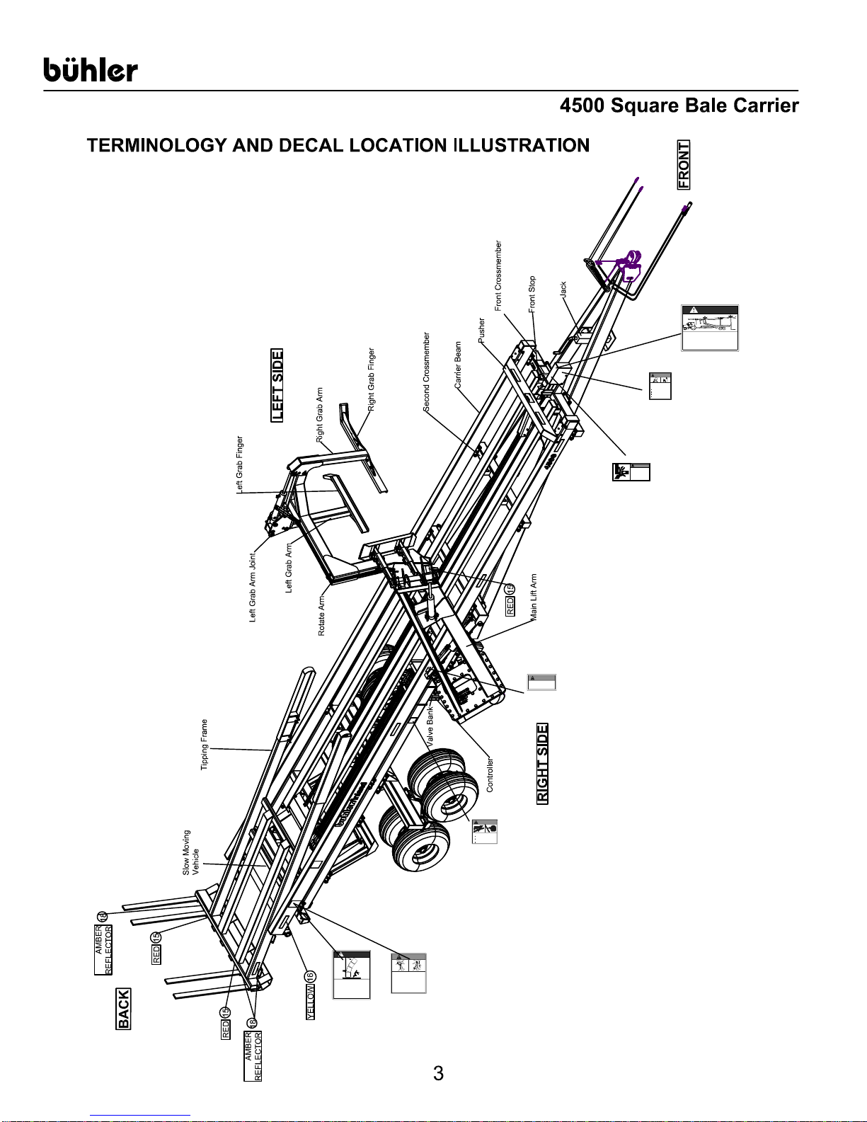
TERMINOLOGY AND DECAL LOCATIONS ILLUSTRATIONS……..………...
3
GENERAL SPECIFICATIONS…..…………………………………………………
4
INTRODUCTION…………………………………………………………………….
5
Serial Decal Location…………………………………………………………….
5
Warranty Registration…………………………………………………………….
5
SAFETY………………………………………………………………………………
6
General Safety Notes…………………………………………………………….
6
Safety Decals……………………………………………………………………..
8
Important Precautions……………………………………………………………
9
PRE OPERATION CHECKLIST...…………………………………………………
10
BALE CARRIER CONTROLLER...………………………………………………..
11
Menu and Controller Overview……..…………………………………………..
12
Calibration Mode……………………….….……………………………………..
13
Manual Mode.…………..……….………………………………………………
19
Auto Mode.………………………………………………………………………..
20
Diagnostic Mode……..…………………………………………………………...
21
OPERATION.………………………………………………………………………..
22
Attaching Bale Carrier to Tractor………………………………………………..
22
Carrier Controls Operation………………………………………………………
24
Loading Operations.……………………………………………………………..
29
Unloading Operations ...………………………………………………………...
32
Transporting Carrier.……………………………………………………………..
34
MAINTENANCE…………………………………………………………………….
35
Fasteners………………………………………………………………………….
35
Hydraulic System…………………………………………………………………
36
Chain/ Sprocket……….………………………………………………………….
36
Wheels/Tires………………………………………………………………………
37
Lubrication……………………………………………….………………………
38
Special Care Conditions………………………………………………………..
39
STORAGE…………………………………………………………………………..
39
End Of Season……………………………………………………………………
39
Start of Season……………………………………………………………………
39
During Season ……………………………………………………………………
40
Stack Storage……………………………………………………………………..
40
APPENDIX LIST……………………………………………………………………..
41
APPENDIX A ASSEMBLY INSTRUCTIONS…………………………………….
42
APPENDIX B HYDRAULIC ASSEMBLY………………………………………...
55
APPENDIX C ELECTRICAL ASSEMBLY………………………………………...
70
APPENDIX D GENERAL ASSEMBLY…………………………………………...
80
APPENDIX E TROUBLE SHOOTING GUIDE…………………………………...
88
CHECKLIST………………………………………………….………………………
93
Pre-delivery…………………………………………………………………...
93
Customer Delivery………………………………………………………………..
93
Page 4
To prevent serious injury or death from falling
21976
SHIELD
WARNING
To prevent serious injury or death from moving
21878
FRAME (over VALVE
before repairing or adjusting or disconnecting.
To prevent serious injury or death from pinching or
place all controls in neutral, stop engine, set park
WARNING
WARNING
ELECTROCUTION HAZARD
To prevent serious injury or death from
electrocution stay at least 50 ft (15 m)
21973
21971
serious pinching injury
if fingers become trapped
Engage transport lock over
lift arm cylinder before
transporting.
RIGHT CARRIER
BEAM (over LIFT
ARM CYLINDER)
DANGER
away from overhead power line when
raising tipping frame or lift arm.
FRA ME (f ront)
MOVING PART HAZARD
parts:
Close and secure guards and shields before
starting.
Keep hand, feet, hair and clothing away from
moving parts.
Disconnect and lockout power source before
adjusting or servicing.
Do not stand or climb on machine when
operating.
FRONT SPROCKET
WARNING
PINCHING HAZARD
Pusher can cause
during pusher return.
PUSHER
21978
DANGER
FALLING BALE HAZARD
KEEP AWAY
bales:
1. Stay away from bale stack when unloading
bale carrier.
2. Keep others away.
LEFT and RIGHT
PINCHING/CRUSHING HAZARD
KEEP AWAY
crushing:
1.Lower lift arm and tipping frame to the ground,
brake, remove ignition key and wait for all moving
parts to stop before servicing, adjusting or repairing.
2. Keep away from lift arm and tipping frame when
engine is running. Keep others away.
LEFT and RIGHT CARRIER
BEAM and MAIN ARM
WARNING
HIGH-PRESSURE FLUID HAZARD
To prevent serious injury or death:
Relieve pressure on system
Wear proper hand and eye protection
when searching for leaks. Use wood or
cardboard instead of hands.
Keep all components in good repair.
21977
21972
Page 5

bühler
4500 Square Bale Carrier
4
GENERAL SPECIFICATIONS:
DIMENSIONS: TIRES:
Length: 42’ 8” (13.0 m) 12.5Lx 15, load range F
Usable Deck Length: 34’ (10.36 m) Farm Highway Service.
Transport Width: 10’ 2” (3.1 m) 6 bolt hubs, heavy-duty hubs
Weight (empty): 9200 lbs. (4181 kg) (approx.) 8 tires
Hitch Weight (empty): 1950 lbs. (884 kg) (approx.)
Hitch Weight (max.): 7500 lbs. (3402 kg) (approx.)
BALE CAPACITY:
GVW: 25 000 lbs. (11340 kg)
8 - 48 x 48 x 96” nominal (1.22 x 1.22 x 2.44 m)
20 - 32 x 35 x 96” nominal (0.81 x0.88 x 2.44 m)
16 - 36 x 48 x 96” nominal (0.91 x 1.22 x 2.44 m)
(requires optional second layer kit)
STACKING UP TO 16 feet (4.8 m) HIGH:
example: 48 x 48 x 96” - 4 high Large Bales
32 x 35 x 96” - 5 high Intermediate Bales
36 x 48 x 96” - 4 high Intermediate Bales
HYDRAULICS:
Recommended range - 12 to 25 US gpm (45 to 80 lpm) @ 3000 psi – closed
center or open center
1 - LIFT ARM CYLINDER - 4 x 18 – 27” retracted
1 - SQUEEZE CYLINDER - 3 x 16 – 24” retracted
1 - ROTATION CYLINDER - 3 x 16 – 24” retracted
2 - TIPPING CYLINDER – 3-1/2 x 36 – 44” retracted
Max recommended pressure: 3500 psi Min. recommended pressure: 2000 psi
Dual 22.2 cu. in. hydraulic motors.
2-speed valve.
Solid-state valve bank.
Control module - operator initiated automatic loading as well as computer control
setting and adjustments.
Electrical - Power 12 volt - neg. ground
Internal fuse protection
TRACTOR POWER REQUIRED:
Minimum 100 hp with adequate braking capacity to safely control 25,000 lbs.
(11,340 kg) GVW trailing load. Do not tow over 32 km/h (20 mph). Towing unit
should weigh 7575 kg (16,700 lbs) or approximately 67% of GVW.
1 pair remote outlets required with variable flow control setting (system should be
set at approximately 13 to 17 gpm). Control valve is restricted to approximately
27 gpm.
Page 6

bühler
4500 Square Bale Carrier
5
INTRODUCTION
CAUTION:
Your 4500 Square Bale Carrier requires minimum a 100 hp (75kw)
tractor. The maximum loaded transportation speed of 20 mph (32 km/h) and 37,440 LB
(16983 kg) must not be exceeded.
This manual has been provided as a reference regarding specifications, safe operation
and maintenance of your agricultural 4500 Square Bale Carrier. Read and understand
this manual and the tractor manual prior operation to obtain the best use of your 4500
Square Bale Carrier. Keep this manual for reference and forward it to new operators
and owners. Contact your local Buhler Inland dealer if you require any assistance,
information or additional manuals.
Your new square bale carrier is designed to pickup, transport, and unload a wide range
of rectangular hay or straw bales measuring approximately 48” (1.22 m) x 48” (1.22 m) x
96” (2.44 m).
Note: Right and Left designations are determined from the operator's position,
facing forward.
Serial Decal Location
The serial decal is located on the left side of the front cross member. Please
record the serial number in the space provided for future reference. The serial decal will
provide the model and date of manufacture of the Square Bale Carrier and will be
required to obtain correct service parts and complete warranty claims.
For your records, record
Serial Number here: _________________________
Warranty Registration
The warranty registration and delivery report MUST be completed within thirty (30) days
of delivery to validate the warranty.
B.I.I. FARGO INC.
FARGO NORTH DAKOTA
farm king
allied
inland
versatile
Page 7
bühler
4500 Square Bale Carrier
6
SAFETY
Read and understand all the safety messages listed in this manual. For your safety and
the safety of others near the machine, learn how to control and operate your 4500
Square Bale Carrier properly. It is your responsibility to inform subsequent operators
and owners of these precautions.
General Safety Notes
Keep young children away from machinery and bales at all times.
Be aware that accidents often happen when the operator is tired or in a hurry to get
finished. Take the time to consider the safest way. Never ignore warning signs of
fatigue.
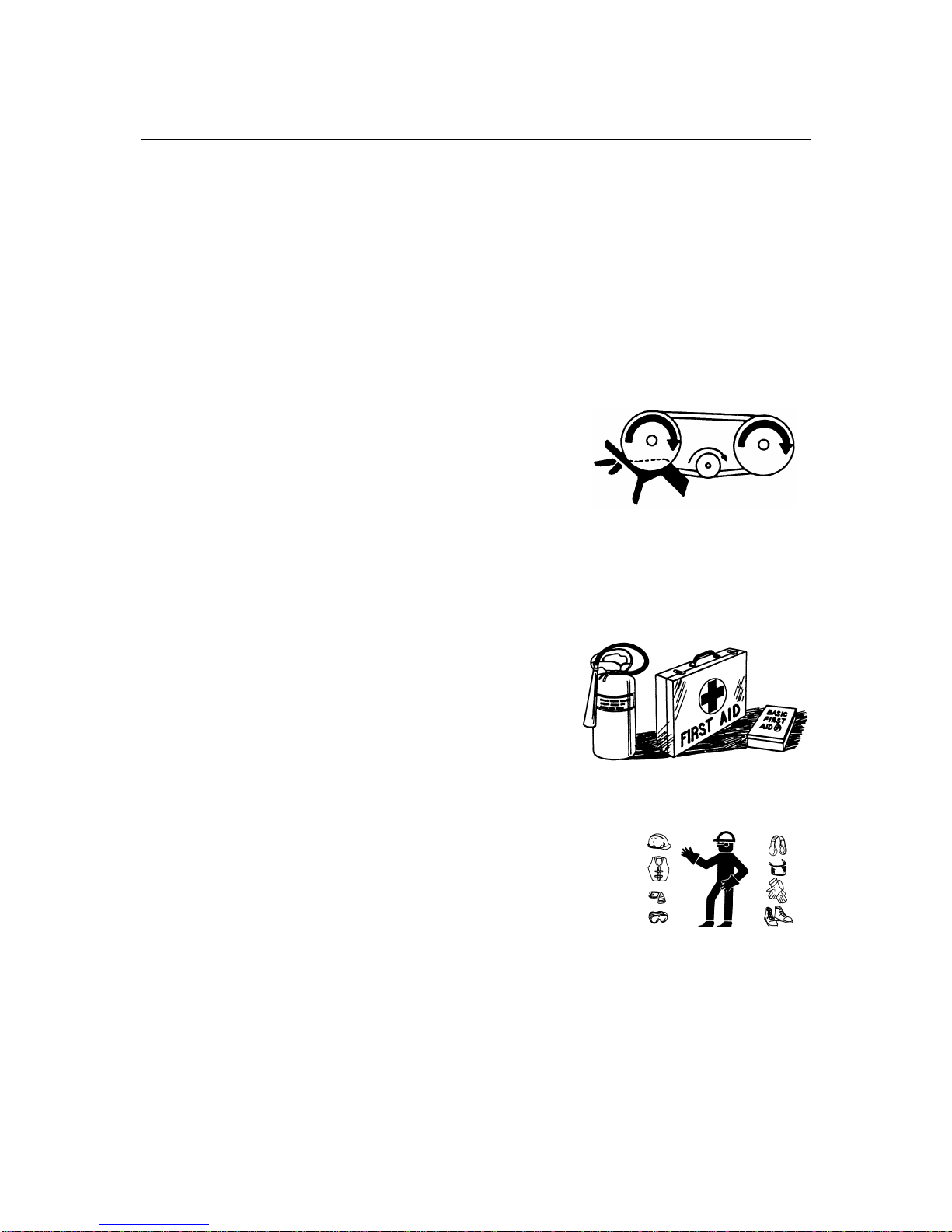
Keep hands, feet, clothing and hair away from moving
parts. Never attempt to clear obstructions or objects
from a machine while the engine is running.
Keep all shields in place. Never alter or remove safety
equipment.
Do not attempt to clear any blockage or reach into the 4500 Square Bale Carrier with
your arm or leg unless the tractor engine is stopped.
Do not load bales of sizes not outlined in the specifications section
Use proper lighting and safety warnings when transporting equipment on public
roads and during darkness. The slow moving vehicle emblem must be visible. Check
with your local law enforcement agency for specific requirements.
Provide a first-aid kit for use in case of
emergencies.
The safety information in this manual does
not replace safety codes, insurance needs, or
laws governing your area. Be sure your machine
meets the standards set by these regulations.
Keep a fire extinguisher with the machine.
Be sure the extinguisher is properly maintained
and be familiar with its proper use.
Wear close-fitting clothing and cover long hair. Never wear
dangling items such as scarves or bracelets.
Remember that YOU are the key to safety. Good safety
practices protect you and the people around you.
Follow all safety messages in the manual and on safety
signs located on the machine.
It is your responsibility to read and understand this manual
completely before operating the bale carrier.
Never leave the tractor unattended while the 4500 Square Bale Carrier is hooked up,
always shut tractor off and remove key before leaving the tractor seat. A child or
even a pet could engage an idling machine.
Keep the 4500 Square Bale Carrier on solid ground; rocks and holes can be
dangerous for operation and movement.
Prior to use, check to ensure the attachment is properly hitched.
Page 8

bühler
4500 Square Bale Carrier
7
Improper use of the 4500 Square Bale Carrier and tractor can cause serious injury
or death.
Never operate 4500 Square Bale Carrier with frayed or damaged hoses or leaking
fittings. A burst could cause one or more hydraulic components to behave erratically
causing serious injury or loss of life.
Operate 4500 Square Bale Carrier only while seated in the tractor seat.
Do not load bales improperly; always load according to the manual’s operation
procedures.
If for some reason you feel the tractor tipping immediately lower lift arm.
Do not raise lift arms to extreme heights while tractor is on an incline. Be alert for
terrain changes and adjust accordingly.
Allow for 4500 Square Bale Carrier and tractor length when turning.
Do not overload the GVW of 37 440 LB (16983 kg) and when loaded keep the speed
below 20 mph (32 km/h).
Before allowing anyone to operate the machine, for however a short time or
distance, make sure they have been instructed in its safe and proper use.
Review the manual and all safety related items with all operators annually,
correct other operators not using recommended procedures before an accident
occurs.
When assembling, operating and servicing machinery, wear all the protective
clothing and personal safety devices that could be necessary for the job at hand.
Never work beneath a raised lift arm unless it is securely supported. The control
handle can be moved or a hydraulic leak could cause the arm to drop resulting in
serious injury or death.
Use only service and repair parts made or approved by the equipment manufacturer,
substituted parts may not meet strength, design, or safety requirements.
Do not modify the machine. Unauthorized modifications may impair the function
and/or safety and affect machine life.
Keep the area used for servicing machinery clean and dry. Wet
or oily floors are slippery. Wet spots can be dangerous when
working with electrical equipment. Be sure all electrical outlets
and tools are properly grounded.
Keep machinery clean. Straw and chaff on hot surfaces are a fire hazard. Do not
allow oil or grease to accumulate on service platforms, ladders or controls. Clean
machines before storage.
Never use gasoline, naphtha or any volatile material for cleaning purposes. These
materials may be toxic and/or flammable.
When storing machinery, cover sharp or extending components to prevent injury
from accidental contact.
Page 9

bühler
4500 Square Bale Carrier
8
Safety Decals
The Terminology And Decal Location Illustration shows the approximate location
and detail of safety decals. To install safety decals ensure the installation area is clean
and dry. Decide on the exact position before you remove the backing paper. Remove
the smallest portion of the split backing paper and align over the specified area.
Carefully press in place. Slowly peel back the remaining paper and smooth the
remaining portion in place. Small air pockets can be pierced with a pin and smoothed
out. Keep all decals clean and replace any that are damaged or missing. Replacement
decals are available from you local dealer. The following pictorials indicate important
precautions to be used during the operation of the 4500 Square Bale Carrier.
1. Read Operator's Manual before using.
3. Close and secure guards before operating.
4. Keep hands, feet, hair and clothing away from moving
parts.
2. Lower lift arm and tipping frame fully, place all controls
in neutral, stop engine, set park brake, remove ignition
key and wait for all moving parts to stop before servicing, adjusting or repairing.
5. Raise lift arm, rotate swing arm over bale deck and
install lift cylinder lock before transporting.
6. Do not transport faster than 20 mph (32 kph) when
loaded.
7. Use hazard flasher when transporting.
8. Do not allow riders.
9. Keep hydraulic components in good condition.
10. Stay away from overhead power lines when raising lift
arm or tipping frame to prevent electrocution.
11. Stay away from lift arm and tipping frame when operating to prevent crushing. Keep others away.
12. Stay away from bale pile when unloading. Bales can tip
over. Keep others away.
13. Review safety instructions annually.
21970
CAUTION
FRAME (front)
21971
Pusher can cause
serious pinching injury
if fingers become trapped
during pusher return.
PINCHING HAZARD
WARNING
PUSHER
ELECTROCUTION HAZARD
To prevent serious injury or death from
electrocution stay at least 50 ft (15 m)
away from overhead power line when
raising tipping frame or lift arm.
DANGER
21973
FRAME (front)
FALLING BALE HAZARD
KEEP AWAY
To prevent serious injury or death from falling
bales:
1. Stay away from bale stack when unloading
bale carrier.
2. Keep others away.
DANGER
21976
LEFT and RIGHT
CARRIER FRAME
LEFT and RIGHT
CARRIER BEAM and
To prevent serious injury or death from pinching or
crushing:
2. Keep away from lift arm and tipping frame when
engine is running. Keep others away.
1. Lower lift arm and tipping frame to the ground,
place all controls in neutral, stop engine, set park
brake, remove ignition key and wait for all moving
parts to stop before servicing, adjusting or repairing.
21972
PINCHING/CRUSHING HAZARD
KEEP AWAY
WARNING
RIGHT CARRIER
BEAM (over LIFT
ARM CYLINDER)
21978
Engage transport lock over
lift arm cylinder before
transporting.
WARNING
FRONT
SPROCKET
WARNING
To prevent serious injury or death from moving
parts:
Close and secure guards and shields before
starting.
Keep hand, feet, hair and clothing away from
moving parts.
Disconnect and lockout power source before
adjusting or servicing.
Do not stand or climb on machine when
operating.
MOVING PART HAZARD
21878
FRAME (over
VALVE BANK)
21977
WARNING
To prevent serious injury or death:
Relieve pressure on system
before repairing or adjusting or disconnecting.
Wear proper hand and eye protection
when searching for leaks. Use wood or
cardboard instead of hands.
Keep all components in good repair.
HIGH-PRESSURE FLUID HAZARD
Page 10

bühler
4500 Square Bale Carrier
9
Important Precautions
The alert symbol is used throughout this manual. It indicates attention is required and
identifies hazards and alerts you that your safety is involved. Follow the recommended
precautions.
CAUTION
Indicates a potentially hazardous situation, which may result in
injury. It may also be used to alert against unsafe practices.
WARNING
The warning symbol indicates a potentially hazardous
situation, which could result in death or serious injury and includes hazards that are
exposed when guards are removed. It may also be used to alert against unsafe
practices.
DANGER
The danger symbol indicates an imminently hazardous
situation, which will result in death or serious injury. This signal word is limited to the
most extreme situations, typically for machine components, which for functional
purposes, cannot be guarded
Page 11

bühler
4500 Square Bale Carrier
10
PRE-OPERATION CHECKLIST
CAUTION
Make sure the tractor has a 100 hp (75 kw) or greater rating
and a mass of 45000 LB (11340 kg). Make sure the drawbar is capable of supporting
the 4500 Square Bale Carrier empty or loaded.
WARNING
The tractor must be equipped with an approved Roll over
Protection Structure (ROPS) and safety belts to help prevent personal injury or death
caused by tractor roll over.
To ensure safe and proper operation of the 4500 Square Bale Carrier, inspect the
following items prior to operation and daily thereafter. Refer to operation, lubrication and
maintenance sections for detailed instructions.
Prior to first use verify that the 4500 Square Bale Carrier has been properly
assembled and that the operator understands the safety, operating, and
maintenance requirements.
Check for missing fasteners and replace if necessary. Refer to maintenance section
for details.
Check and maintain proper tire pressure of 90 psi (620 kpa).
Check for loose wheel bolts. Bolts must be torque to 125 ft LB (170 Nm).
Clean 4500 Square Bale Carrier of any foreign material that may have accumulated
from previous run.
Lubricate all points requiring daily lubrication.
Check chain tension and adjust if necessary with front sprocket adjusting bolt
(approximately 6” (15 cm) of upward slack). This is verified by raising the chain by
hand.
Ensure top surface of bale carrier beams are properly coated with a graphite coating
to reduce bale friction while pushing bales back.
Ensure that the tractor used to pull the 4500 Square Bale Carrier is in working order
according to the tractor manual.
Verify that the 4500 Square Bale Carrier is properly coupled to the tractor with the
safety chain.
Inspect all safety reflective decals, slow moving vehicle decals and lights where
applicable.
Inspect the hydraulic system on the 4500 Square Bale Carrier and your tractor for
leaks or any other damage.
Ensure the control handle actions reflect the movements of the 4500 Square Bale
Carrier.
Inspect all electrical connections to ensure proper function of the machine
Ensure transport safety chain is disengaged from bale lift arm and stored on chain
lug located on second cross member. Failure to do so may cause damage to lift arm.
Page 12

bühler
4500 Square Bale Carrier
11
Bale Carrier Controller
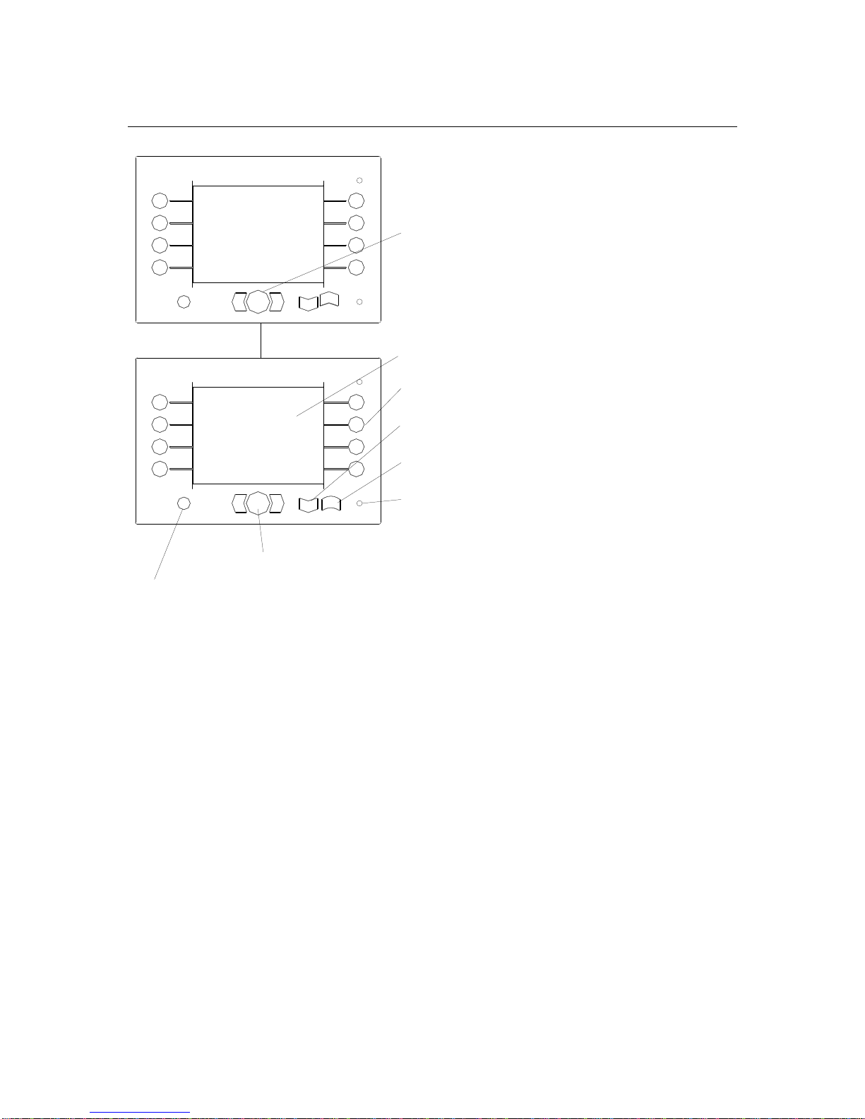
Menu and Controller Overview
DISPLAY UNI
DISPLAY UNIDISPLAY UNI
DISPLAY UNI
T
CAB HARNESS
TOTAL LENGTH 16'
1
2
3
4444
5
6
7
8
OK
ESC
4500 SQUARE
BALE CARRIER
VERSION 1.0.05
GROUND CONNECTION
IGNITION POWER
CONNECTION
PLUG TO TRACTOR
CONTROL HANDLE
CONTROL HANDLECONTROL HANDLE
CONTROL HANDLE
POWER CONNECTOR
POWER CONNECTORPOWER CONNECTOR
POWER CONNECTOR
COMM/POWER CONNECTOR
COMM/POWER CONNECTORCOMM/POWER CONNECTOR
COMM/POWER CONNECTOR
bühler
inland
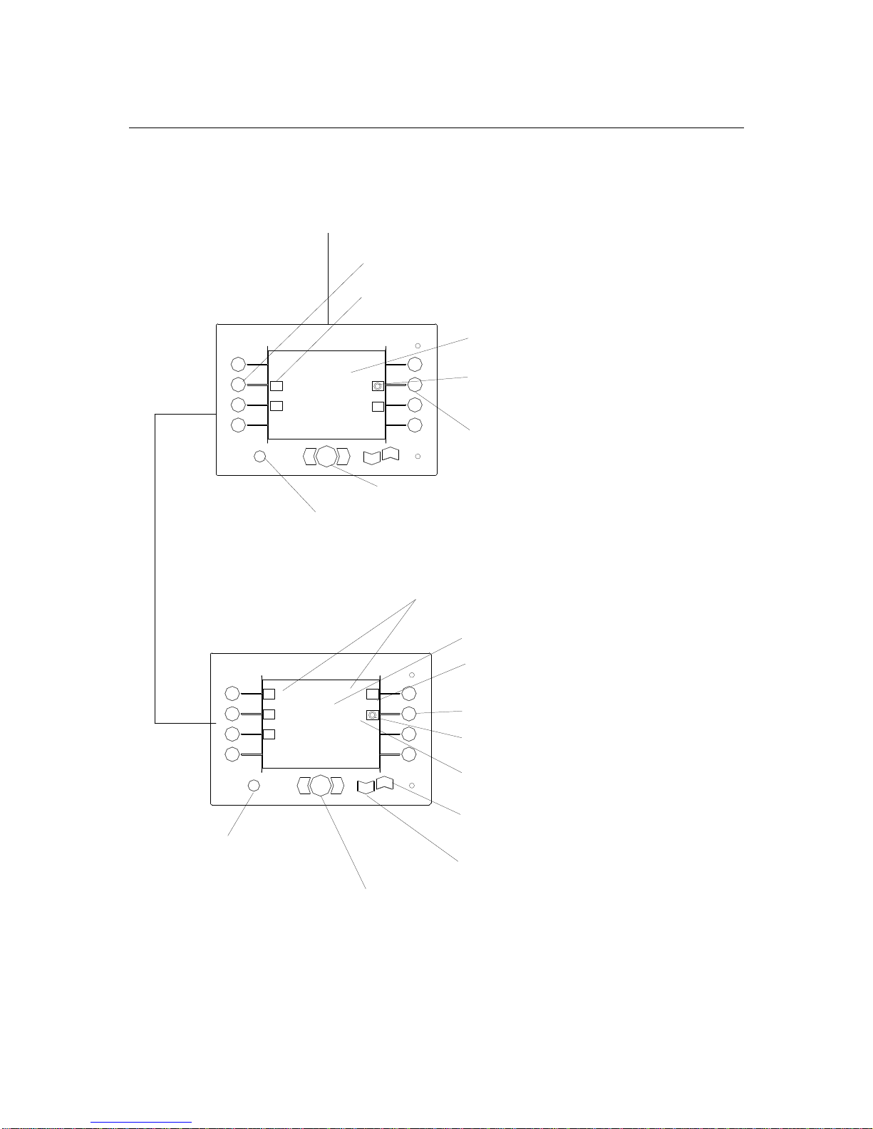
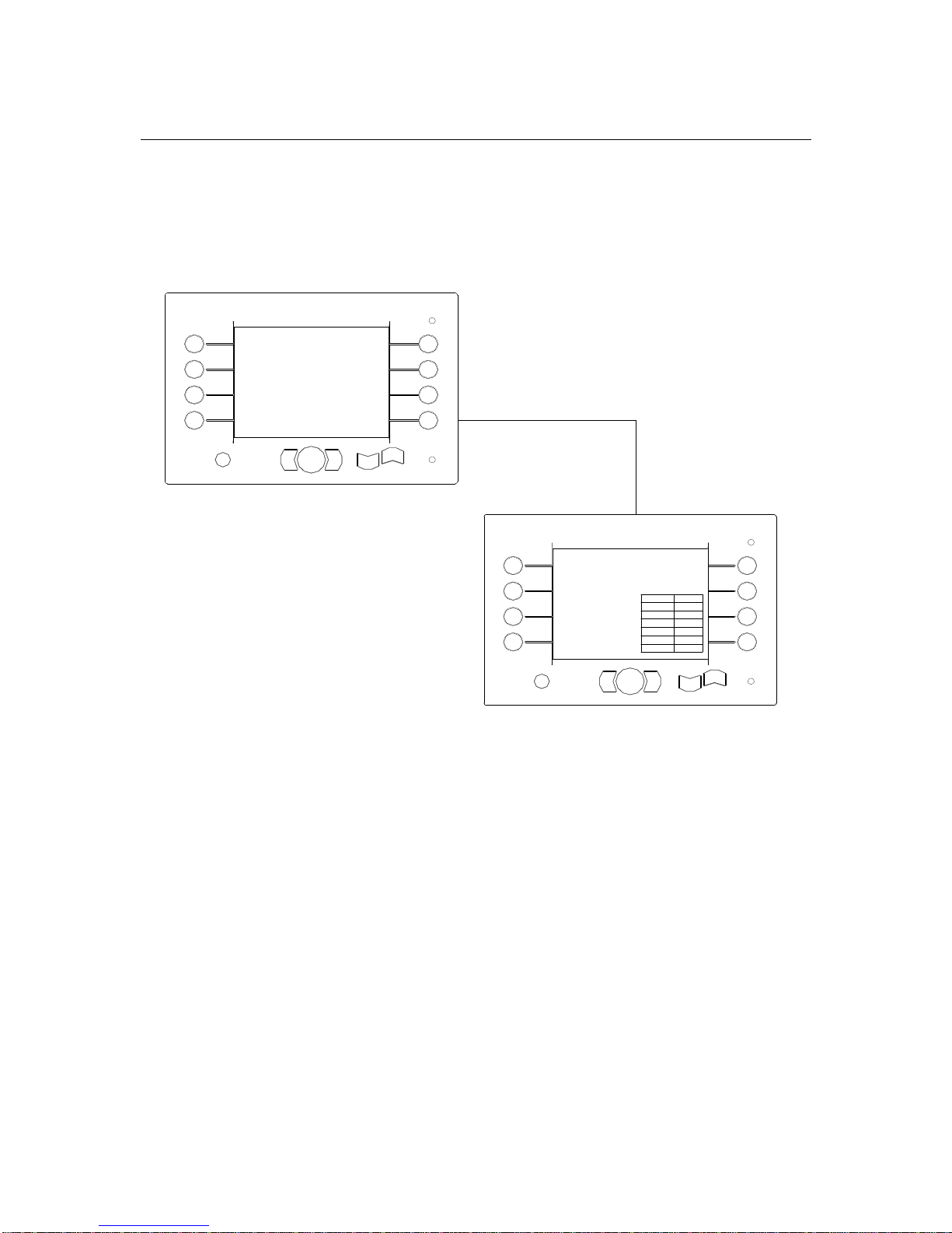
Power for the Display Box (located in the tractor cab) and the Controller (located near
the valve bank) comes from the Power connection connected to your tractor power
accessory port. The Controller is turned on by turning the tractor key to “accessory” or
by turning on the tractor. The first menu that appears on the Display unit is the
Buhler/Inland Logo. To by-pass this menu press the “O.K.” button located on the front
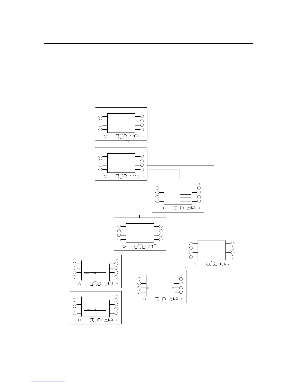
panel. The following flow diagram outlines the menu structure found in the Display unit.
There are several common features used to navigate through the menu structure. They
are shown in the attached flow diagram. Any unique functionality specific to the menu is
described in detail in the corresponding menu.
Page 13
bühler
4500 Square Bale Carrier
12
MANUAL MODE
AUTO MODE
CALIBRATION
MODE
DIAGNOSTIC
MODE
1
2
3
4444
5
6
7
8
OK
ESC
4500 SQUARE
BALE CARRIER
4500 SQUARE BALE CARRIER
VERSION 1.0.05
1
2
3
4444
5
6
7
8
OK
ESC
VERSION 1.0.05
PRESS O.K. FOR
NEXT MENU
1-8 BUTTON; FUNCTION SELECTION BUTTON
MENU HEADING; NAME OF CURRENT MENU
DOWN OR LEFT BUTTON; PRESS AND
HOLD TO MOVE FEATURE DOWN OR LEFT
O.K. BUTTON; PRESS TO ACCEPT INPUT
ESC BUTTON; PRESS TO EXIT OUT OF CURRENT
MENU AND RETURN TO PREVIOUS MENU
LED; COMMUNICATION STATUS, BLINKING
RED LED = COMMUNICATION ERROR. NO
LED = COMMUNICATION O.K
UP OR RIGHT BUTTON; PRESS AND HOLD TO
MOVE FEATURE DOWN OR LEFT
buhler
bühler
inland
Page 14
bühler
4500 Square Bale Carrier
13
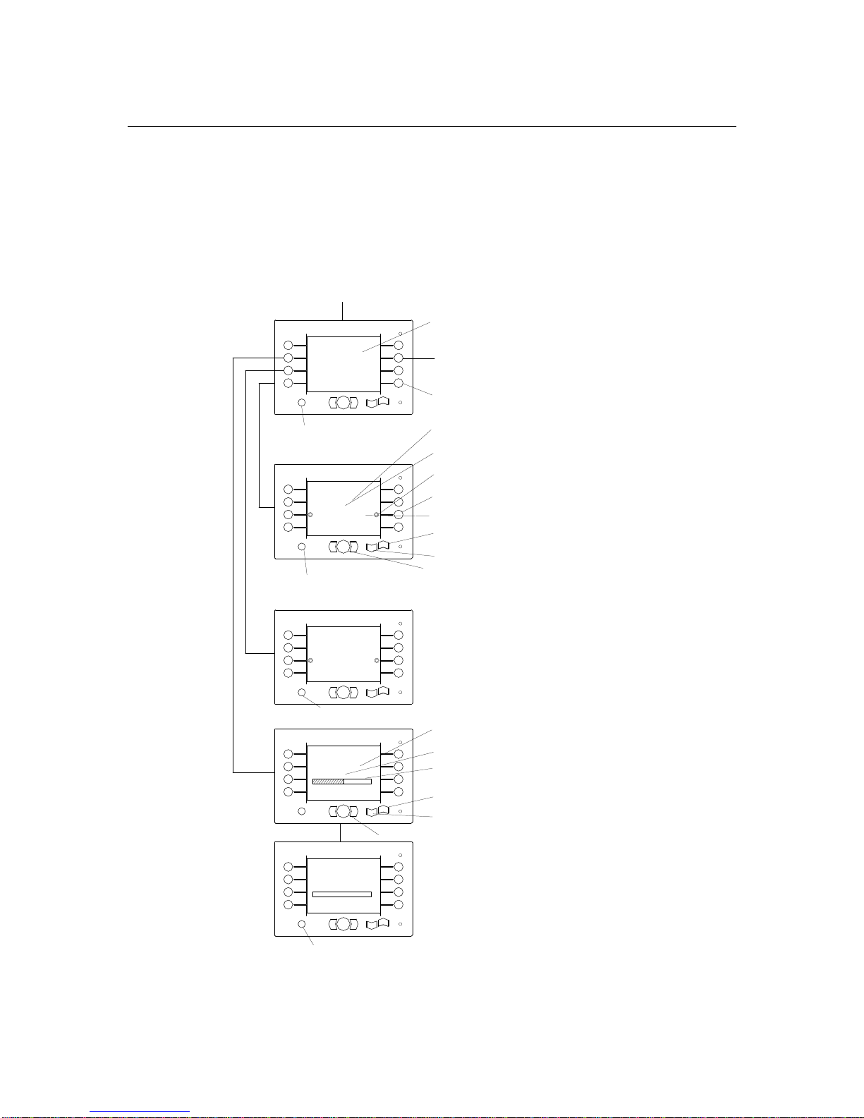
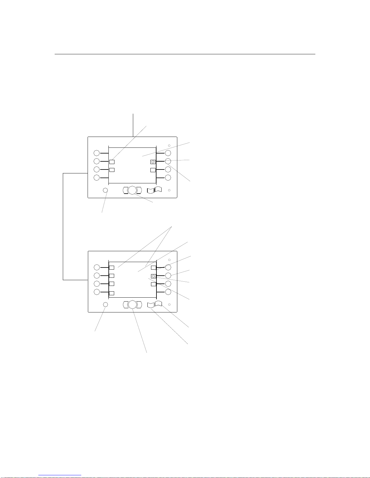
Calibration Mode
The Calibration Mode is used to calibrate (setup) the full range of motion of the bale
carrier. This section is used to define limits of travel for all functions as well as setting
the Hydraulic Specification, Custom Bale Setup and Screen Brightness levels.
NOTE:
Calibration of the unit has been factory set. Calibration is required only if there is
a change in sensors, sensor links, tractor and or the controller. The following flow
diagram shows the menu layout for the Calibration mode.
CALIBRATION MODE
CLAMP OPEN PRESSURE
Min
Max
CALIBRATION MODE
LIFT ARM
UP LIMITDOWN LIMIT
ESC TO RETURN/OK TO STORE
CALIBRATION MODE
CALIBRATION MODE
LIFT ARM
TIPPING
FRAME
PUSHER
ROTATE ARM
CLAMP
ROTATE ARM
LEFT LIMIT
RIGHT LIMIT
ESC TO RRETURN/OK TO STORE
ESC TO RETURN/OK TO STORE
1.55V
1.55V
1.55V
NEXT PAGE
CALIBRATION MODE OR M ACHINE
CALIBRATION MODE OR M ACHINE CALIBRATION MODE OR M ACHINE
CALIBRATION MODE OR M ACHINE
SETUP; SETTING THE LIMIT OF TRAV
SETUP; SETTING THE LIMIT OF TRAVSETUP; SETTING THE LIMIT OF TRAV
SETUP; SETTING THE LIMIT OF TRAVEL
OF EACH FUNCTIO
OF EACH FUNCTIOOF EACH FUNCTIO
OF EACH FUNCTIO
N
1
2
3
4444
5
6
7
8
OK
ESC
1
2
3
4444
5
6
7
8
OK
ESC
CALIBRATION MODE
CLAMP CLOSE PRESSURE
Min
Max
ESC TO RETURN/OK TO STORE
1.55V
1
2
3
4444
5
6
7
8
OK
ESC
1
2
3
4444
5
6
7
8
OK
ESC
1
2
3
4444
5
6
7
8
OK
ESC
FUNCTION SELECTION B UTTON;
FUNCTION SELECTION B UTTON; FUNCTION SELECTION B UTTON;
FUNCTION SELECTION B UTTON;
PRESS TO SELECT FU NCTION
PRESS TO SELECT FU NCTIONPRESS TO SELECT FU NCTION
PRESS TO SELECT FU NCTION
PRESS SO ENTER SUB MENU
PRESS SO ENTER SUB MENUPRESS SO ENTER SUB MENU
PRESS SO ENTER SUB MENU
PRESS
PRESS PRESS
PRESS
TO EXIT THIS MENU;
RETURN TO PREVIOUS MENU
FUNCTION HEADING; N AME OF
FUNCTION HEADING; N AME OF FUNCTION HEADING; N AME OF
FUNCTION HEADING; N AME OF
CURRENT FUNCTION
CURRENT FUNCTIONCURRENT FUNCTION
CURRENT FUNCTION
CURRENT FUNCTION'S
SEN
SENSEN
SENSOOOO
R VOTAGE READING
FUNCTION ICON; ICON A PPEARS
FUNCTION ICON; ICON A PPEARS FUNCTION ICON; ICON APPEARS
FUNCTION ICON; ICON A PPEARS
WHEN FUNCTION IS SELE CTED
WHEN FUNCTION IS SELE CTEDWHEN FUNCTION IS SELE CTED
WHEN FUNCTION IS SELE CTED
FUNCTION
FUNCTIONFUNCTION
FUNCTION
NAME; FUNCTION'S
LIMIT
LIMIT LIMIT
LIMIT
UP OR RIGHT ARROW BUT TON; PRESS AND
UP OR RIGHT ARROW BUT TON; PRESS AND UP OR RIGHT ARRO W BUTTON; PRESS AND
UP OR RIGHT ARROW BUT TON; PRESS AND
HOLD TO MOVE FUNCT ION
HOLD TO MOVE FUNCT IONHOLD TO MOVE FUNCT ION
HOLD TO MOVE FUNCT ION
O.K. BUTTON; PRESS TO STORE THE DESIRE VALUE
O.K. BUTTON; PRESS TO STORE THE DESIRE VALUEO.K. BUTTON; PRESS TO STORE THE DESIRE VALUE
O.K. BUTTON; PRESS TO STORE THE DESIRE VALUE
FUNCTION SELECTION BUTTON;
FUNCTION SELECTION BUTTON; FUNCTION SELECTION BUTTON;
FUNCTION SELECTION BUTTON;
PRESS TO SELECT FUNCTION
PRESS TO SELECT FUNCTIONPRESS TO SELECT FUNCTION
PRESS TO SELECT FUNCTION
DOWN OR LEFT ARROW BU TTON; PRESS
DOWN OR LEFT ARROW BU TTON; PRESS DOWN OR LEFT ARROW BU TTON; PRESS
DOWN OR LEFT ARROW BU TTON; PRESS
AND HOLD TO MOVE F UNCTION
AND HOLD TO MOVE F UNCTIONAND HOLD TO MO VE FUNCTION
AND HOLD TO MOVE F UNCTION
PRESS
PRESS PRESS
PRESS
TO EXIT THIS MENU;
RETURN TO PREVIOUS MENU
PRESS
PRESS PRESS
PRESS
TO EXIT THIS MENU;
RETURN TO PREVIOUS MENU
PRESS
PRESS PRESS
PRESS
TO EXIT THIS MENU;
RETURN TO PREVIOUS MENU
FUNCTION HEADING; NAM E OF CURRENT
FUNCTION HEADING; NAM E OF CURRENT FUNCTION HEADING; NAM E OF CURRENT
FUNCTION HEADING; NAM E OF CURRENT
FUNCTION
FUNCTIONFUNCTION
FUNCTION
CURRENT FUNCTION'S
SEN
SENSEN
SENSOOOO
R VOTAGE
READING
BAR GRAPH; VISUAL REPRESENTATION OF
BAR GRAPH; VISUAL REPRESENTATION OF BAR GRAPH; VISUAL REPRESENTATION OF
BAR GRAPH; VISUAL REPRESENTATION OF
PRESSURE SETTING
PRESSURE SETTINGPRESSURE SETTING
PRESSURE SETTING
UP OR
UP OR UP OR
UP OR
OPEN
ARROW BUTTON; PRESS
ARROW BUTTON; PRESS ARROW BUTTON; PRESS
ARROW BUTTON; PRESS
AND HOLD TO MOVE FU NCTION
AND HOLD TO MOVE FU NCTIONAND HOLD TO MOVE FUNCTION
AND HOLD TO MOVE FU NCTION
O.K. BUTTON; PRESS TO STORE THE DESIRE VALUE
O.K. BUTTON; PRESS TO STORE THE DESIRE VALUEO.K. BUTTON; PRESS TO STORE THE DESIRE VALUE
O.K. BUTTON; PRESS TO STORE THE DESIRE VALUE
DOWN OR
DOWN OR DOWN OR
DOWN OR
CLOSE
A
A A
A
RRO
W BUTTON;
W BUTTON; W BUTTON;
W BUTTON;
PRESS AND HOLD TO MOVE FUNCTION
PRESS AND HOLD TO MOVE FUNCTIONPRESS AND HOLD TO MOVE FUNCTION
PRESS AND HOLD TO MOVE FUNCTION
bühler
bühler
bühler
bühler
bühler
Page 15
bühler
4500 Square Bale Carrier
14
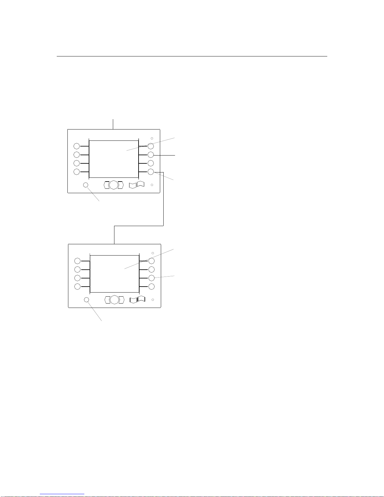
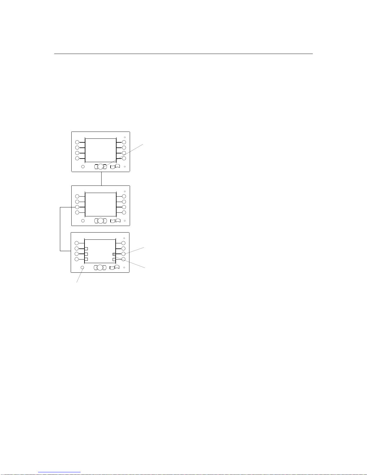
The following flow diagram shows sub-menus required to setup other functions. These
functions include the set up of the Hydraulic system, Custom Bale setup and the Screen
Brightness level for your Display unit.
CALIBRATION MODE
LIFT ARM
TIPPING
FRAME
PUSHER
ROTATE ARM
CLAMP
NEXT PAGE
CALIBRATION MODE
SET HYD
SYSTEM
SET CUSTOM
BALE SIZE
SCREEN
BRIGHTNESS
PREVIOUS
PAGE
CALIBRATION MODE OR MACHINE SETUP; SETTING
CALIBRATION MODE OR MACHINE SETUP; SETTING CALIBRATION MODE OR MACHINE SETUP; SETTING
CALIBRATION MODE OR MACHINE SETUP; SETTING
THE LIMIT OF TRAV
THE LIMIT OF TRAVTHE LIMIT OF TRAV
THE LIMIT OF TRAVEL OF EACH FUNCTIO
OF EACH FUNCTIO OF EACH FUNCTIO
OF EACH FUNCTIO
N
1
2
3
4444
5
6
7
8
OK
ESC
1
2
3
4444
5
6
7
8
OK
ESC
SET HYD SYTEM FIRST
FUNCTION SELECTION BUTTON; PRESS TO SELECT
FUNCTION SELECTION BUTTON; PRESS TO SELECT FUNCTION SELECTION BUTTON; PRESS TO SELECT
FUNCTION SELECTION BUTTON; PRESS TO SELECT
FUNCTION
FUNCTIONFUNCTION
FUNCTION
PRESS
PRESS PRESS
PRESS TO ENTER SUB MENU
O ENTER SUB MENUO ENTER SUB MENU
O ENTER SUB MENU
PRESS
PRESS PRESS
PRESS
TO EXIT THIS MENU;
RETURN TO PREVIOUS MENU
BLINKING TEXT; INFORMATION
BLINKING TEXT; INFORMATIONBLINKING TEXT; INFORMATION
BLINKING TEXT; INFORMATION MESSAGE
ESSAGEESSAGE
ESSAGE
T
O SET HYDRAULIC SYSTEM
O SET HYDRAULIC SYSTEMO SET HYDRAULIC SYSTEM
O SET HYDRAULIC SYSTEM
FUNCTION SELECTION BUTTON; PRESS TO
FUNCTION SELECTION BUTTON; PRESS TOFUNCTION SELECTION BUTTON; PRESS TO
FUNCTION SELECTION BUTTON; PRESS TO
SELECT FUNCTION
SELECT FUNCTIONSELECT FUNCTION
SELECT FUNCTION
PRESS
PRESS PRESS
PRESS
TO EXIT THIS MENU;
RETURN TO PREVIOUS MENU
bühler
bühler
Page 16
bühler
4500 Square Bale Carrier
15
The following flow diagram shows sub-menus of the Brightness Setting and Hydraulic
System Setting. The hydraulic Setup allows the operator to match the unit’s hydraulic
system to the tractor’s hydraulic specification. The unit’s hydraulic system can operate
as an OPEN CENTER or CLOSE CENTER depending on the attached tractor. To set
the Hydraulic system, simply choose the corresponding system. Select
OPEN CENTER
when using tractors with
LOAD SENSING
hydraulic system.
HYDRAULIC SYSTEM
OPEN
CENTER
CLOSE
CENTER
ESC TO RETURN
CALIBRATION MODE
SET HYD
SYSTEM
SET CUSTOM
BALE SIZE
SCREEN
BRIGHTNESS
PREVIOUS
PAGE
SCREEN BRIGHTNESS
BRIGHTER DARKER
80%
ESC TO RETURN
1
2
3
4444
5
6
7
8
OK
ESC
SET HYD SYTEM FIRST
1
2
3
4444
5
6
7
8
OK
ESC
CALIBRATION MODE
1
2
3
4444
5
6
7
8
OK
ESC
BLINKING TEXT; INFORMATION
BLINKING TEXT; INFORMATIONBLINKING TEXT; INFORMATION
BLINKING TEXT; INFORMATION
M
ESSAGE
ESSAGEESSAGE
ESSAGE TO SET HYDRAULIC SYSTEM
O SET HYDRAULIC SYSTEMO SET HYDRAULIC SYSTEM
O SET HYDRAULIC SYSTEM
FUNCTION SELECTION BUTTON;
FUNCTION SELECTION BUTTON; FUNCTION SELECTION BUTTON;
FUNCTION SELECTION BUTTON;
PRESS TO SELECT FUNCTION
PRESS TO SELECT FUNCTIONPRESS TO SELECT FUNCTION
PRESS TO SELECT FUNCTION
FUNCTION HEADING; NAME OF CURRENT
FUNCTION HEADING; NAME OF CURRENT FUNCTION HEADING; NAME OF CURRENT
FUNCTION HEADING; NAME OF CURRENT
FUNCTION
FUNCTIONFUNCTION
FUNCTION
LIGHT INTENSITY VALUE;
LIGHT INTENSITY VALUE;LIGHT INTENSITY VALUE;
LIGHT INTENSITY VALUE;
SHOWS CURRENT
LIGHT INTENSITY GIVEN BY THE DISPLAY UNIT
FUNCTION BUTTON; PRESS
FUNCTION BUTTON; PRESS FUNCTION BUTTON; PRESS
FUNCTION BUTTON; PRESS
TO DECREASE
LIGHT INTENSITY (MINIMUN 10%)
PRESS
PRESS PRESS
PRESS
TO EXIT THIS MENU;
RETURN TO PREVIOUS MENU
FUNCTION BUTTON; PRESS
FUNCTION BUTTON; PRESS FUNCTION BUTTON; PRESS
FUNCTION BUTTON; PRESS
TO INCREASE LIGHT INTENSITY
(MAXIMUN 100%)
PRESS
PRESS PRESS
PRESS
TO EXIT THIS MENU;
RETURN TO PREVIOUS MENU
FUNCTION HEADING; NAME OF
FUNCTION HEADING; NAME OF FUNCTION HEADING; NAME OF
FUNCTION HEADING; NAME OF
CURRENT FUNCTION
CURRENT FUNCTIONCURRENT FUNCTION
CURRENT FUNCTION
FUNCTION; CLOSE CENTER FOR CLOSE
FUNCTION; CLOSE CENTER FOR CLOSE FUNCTION; CLOSE CENTER FOR CLOSE
FUNCTION; CLOSE CENTER FOR CLOSE
CENTER TRACTOR
CENTER TRACTORCENTER TRACTOR
CENTER TRACTOR
FUNCTION SELECTION BUTTON;
FUNCTION SELECTION BUTTON; FUNCTION SELECTION BUTTON;
FUNCTION SELECTION BUTTON;
PRESS TO SELECT FUNCTION
PRESS TO SELECT FUNCTIONPRESS TO SELECT FUNCTION
PRESS TO SELECT FUNCTION
FUNCTION;
FUNCTION; FUNCTION;
FUNCTION;
OPEN
CENTER FOR
CENTER FOR CENTER FOR
CENTER FOR
OPEN
CENTER TRACTOR
CENTER TRACTORCENTER TRACTOR
CENTER TRACTOR
FUNCTION
FUNCTIONFUNCTION
FUNCTION
ICON;
ICON WILL APPEAR WHEN
FUNCTION IS SELECTED
PRESS
PRESS PRESS
PRESS
TO EXIT THIS MENU;
RETURN TO PREVIOUS MENU
bühler
bühler
bühler
Page 17
bühler
4500 Square Bale Carrier
16
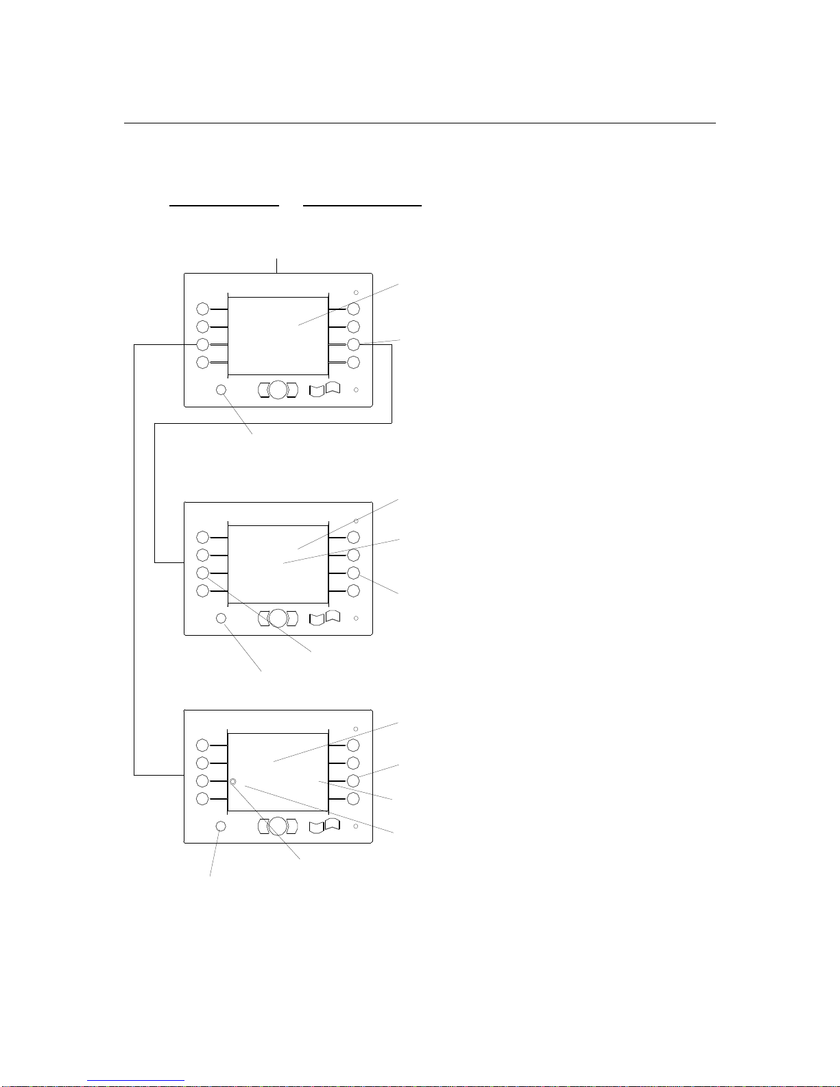
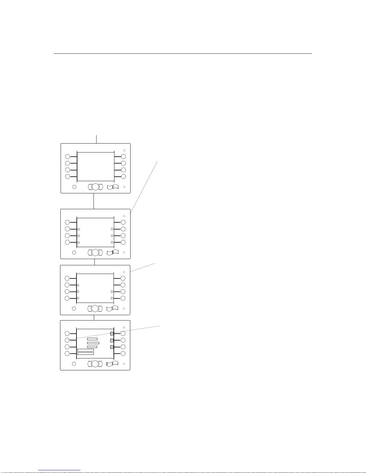
The following flow diagram shows sub-menu for Custom Bale Size setup. Custom Bale
Size setup is design so the user can define various parameters to load the bales. It is
recommended that this setup be perform using actual bales.
CUSTOM BALE SETUP
DOUBLE
STACK
CUSTOM 1
CUSTOM 2
ESC TO RETURN/OK TO STORE
SET HYD
SYSTEM
SET CUSTOM
BALE SIZE
SCREEN
BRIGHTNESS
PREVIOUS
PAGE
CUSTOM 3
1
2
3
4444
5
6
7
8
OK
ESC
SET HYD SYTEM FIRST
1
2
3
4444
5
6
7
8
OK
ESC
N
BLINKING TEXT; INFORMATION
BLINKING TEXT; INFORMATIONBLINKING TEXT; INFORMATION
BLINKING TEXT; INFORMATION
M
ESSAGE
ESSAGEESSAGE
ESSAGE
TO
SET HYDRAULIC SYSTEM
SET HYDRAULIC SYSTEM SET HYDRAULIC SYSTEM
SET HYDRAULIC SYSTEM
FUNCTION SELECTION BUTTON;
FUNCTION SELECTION BUTTON; FUNCTION SELECTION BUTTON;
FUNCTION SELECTION BUTTON;
PRESS TO SELECT FUNCTION
PRESS TO SELECT FUNCTIONPRESS TO SELECT FUNCTION
PRESS TO SELECT FUNCTION
FUNCTION HEADING; NAME OF
FUNCTION HEADING; NAME OF FUNCTION HEADING; NAME OF
FUNCTION HEADING; NAME OF
CURRENT FUNCTION
CURRENT FUNCTIONCURRENT FUNCTION
CURRENT FUNCTION
PRESS
PRESS PRESS
PRESS
TO EXIT THIS MENU;
RETURN TO PREVIOUS MENU
O.K. BUTTON; PRESS TO STORE SELECTION
O.K. BUTTON; PRESS TO STORE SELECTIONO.K. BUTTON; PRESS TO STORE SELECTION
O.K. BUTTON; PRESS TO STORE SELECTION
PRESS
PRESS PRESS
PRESS
TO EXIT THIS MENU;
RETURN TO PREVIOUS MENU
FUNCTION
FUNCTIONFUNCTION
FUNCTION
STATUS; SHOWS STATUS OF FUNCTION
(DEFAULT= "NO")
FUNCTION SELECTION BUTTON;
FUNCTION SELECTION BUTTON; FUNCTION SELECTION BUTTON;
FUNCTION SELECTION BUTTON;
PRESS TO SELECT FUNCTION
PRESS TO SELECT FUNCTIONPRESS TO SELECT FUNCTION
PRESS TO SELECT FUNCTION
FUNCTION
FUNCTION FUNCTION
FUNCTION
ICON; ICON APPEARS
WHEN SELECTED
bühler
bühler
Page 18
bühler
4500 Square Bale Carrier
17
This menu selection allows the user to setup up to three (3) different custom bale sizes
for picking. It also gives the user the ability to double stack the custom bale sizes.
Follow the menu below to custom setup bale sizes.
CUSTOM 2
SET
PUSH FULL
SET BALE
1 ROW HEIGHT
SET
BALE DOWN
ESC TO RETURN/OK TO STORE
CLAMP
ROTATE
1.55V
1.55V
1.55V
350
1.55V
1
2
3
4444
5
6
7
8
OK
ESC
CALIBRATION MODE
CUSTOM BALE SETUP
DOUBLE
STACK
CUSTOM 1
CUSTOM 2
ESC TO RETURN/OK TO STORE
CUSTOM 3
1
2
3
4444
5
6
7
8
OK
ESC
N
CALIBRATION MODE
FUNCTION HEADING; NAME OF
FUNCTION HEADING; NAME OF FUNCTION HEADING; NAME OF
FUNCTION HEADING; NAME OF
CURRENT FUNCTION
CURRENT FUNCTIONCURRENT FUNCTION
CURRENT FUNCTION
O.K. BUTTON; PRESS TO STORE SELECTION
O.K. BUTTON; PRESS TO STORE SELECTIONO.K. BUTTON; PRESS TO STORE SELECTION
O.K. BUTTON; PRESS TO STORE SELECTION
PRESS
PRESS PRESS
PRESS
TO EXIT THIS MENU;
RETURN TO PREVIOUS MENU
FUNCTION
FUNCTIONFUNCTION
FUNCTION
STATUS; SHOWS STATUS OF FUNCTION
(DEFAULT "NO")
FUNCTION SELECTION BUTTON; PRESS
FUNCTION SELECTION BUTTON; PRESS FUNCTION SELECTION BUTTON; PRESS
FUNCTION SELECTION BUTTON; PRESS
TO SELECT FUNCTION
TO SELECT FUNCTIONTO SELECT FUNCTION
TO SELECT FUNCTION
FUNCTION
FUNCTION FUNCTION
FUNCTION
ICON; ICON APPEARS WHEN
SELECTED
FUNCTION HEADING; NAME OF CURRENT
FUNCTION HEADING; NAME OF CURRENT FUNCTION HEADING; NAME OF CURRENT
FUNCTION HEADING; NAME OF CURRENT
FUNCTION
FUNCTIONFUNCTION
FUNCTION
FUNCTION SELECTION BUTTON; PRESS TO
FUNCTION SELECTION BUTTON; PRESS TO FUNCTION SELECTION BUTTON; PRESS TO
FUNCTION SELECTION BUTTON; PRESS TO
SELECT FUNCTION
SELECT FUNCTIONSELECT FUNCTION
SELECT FUNCTION
SENSOR
SENSOR SENSOR
SENSOR
READING
;
; ;
;
INDICATE THE
POSTION OF THE CURRENT FUNCTION
FUNCTION
FUNCTION FUNCTION
FUNCTION
NAME
;
; ;
;
NAME OF FUNCTION
SELECTED
FUNCTION
FUNCTION FUNCTION
FUNCTION
ICON
;
; ;
;
ICON APPEAR WHEN
SELECTED
UUUU
P/ OPEN/ FORWARD
ARROW BUTTON;
ARROW BUTTON; ARROW BUTTON;
ARROW BUTTON;
PRESS AND HOLD TO MOVE FUNCTION
PRESS AND HOLD TO MOVE FUNCTIONPRESS AND HOLD TO MOVE FUNCTION
PRESS AND HOLD TO MOVE FUNCTION
DOW
DOWDOW
DOW
N/CLOSE/BACK
A
A A
A
RRO
W BUTTON;
W BUTTON; W BUTTON;
W BUTTON;
PRESS AND HOLD TO MOVE FUNCTION
PRESS AND HOLD TO MOVE FUNCTIONPRESS AND HOLD TO MOVE FUNCTION
PRESS AND HOLD TO MOVE FUNCTION
O.K. BUTTON; PRESS TO STORE VALUE. ONCE VALUE
O.K. BUTTON; PRESS TO STORE VALUE. ONCE VALUE O.K. BUTTON; PRESS TO STORE VALUE. ONCE VALUE
O.K. BUTTON; PRESS TO STORE VALUE. ONCE VALUE
IS STORED ICON FRON FUNCTION WILL DISAPPEAR.
IS STORED ICON FRON FUNCTION WILL DISAPPEAR.IS STORED ICON FRON FUNCTION WILL DISAPPEAR.
IS STORED ICON FRON FUNCTION WILL DISAPPEAR.
PRESS
PRESS PRESS
PRESS
TO EXIT THIS MENU;
RETURN TO PREVIOUS MENU
THESE FUNCTIO
THESE FUNCTIOTHESE FUNCTIO
THESE FUNCTIONS DO NOT REQUIRE SETTING.
DO NOT REQUIRE SETTING. DO NOT REQUIRE SETTING.
DO NOT REQUIRE SETTING.
VALUES ARE OBTAINED FROM MACHINE SETUP.
VALUES ARE OBTAINED FROM MACHINE SETUP.VALUES ARE OBTAINED FROM MACHINE SETUP.
VALUES ARE OBTAINED FROM MACHINE SETUP.
FUNCTION BUTTON: PRESS TO CHANGE STATUS TO "Y"
FUNCTION BUTTON: PRESS TO CHANGE STATUS TO "Y"FUNCTION BUTTON: PRESS TO CHANGE STATUS TO "Y"
FUNCTION BUTTON: PRESS TO CHANGE STATUS TO "Y"
bühler
bühler
Page 19
bühler
4500 Square Bale Carrier
18
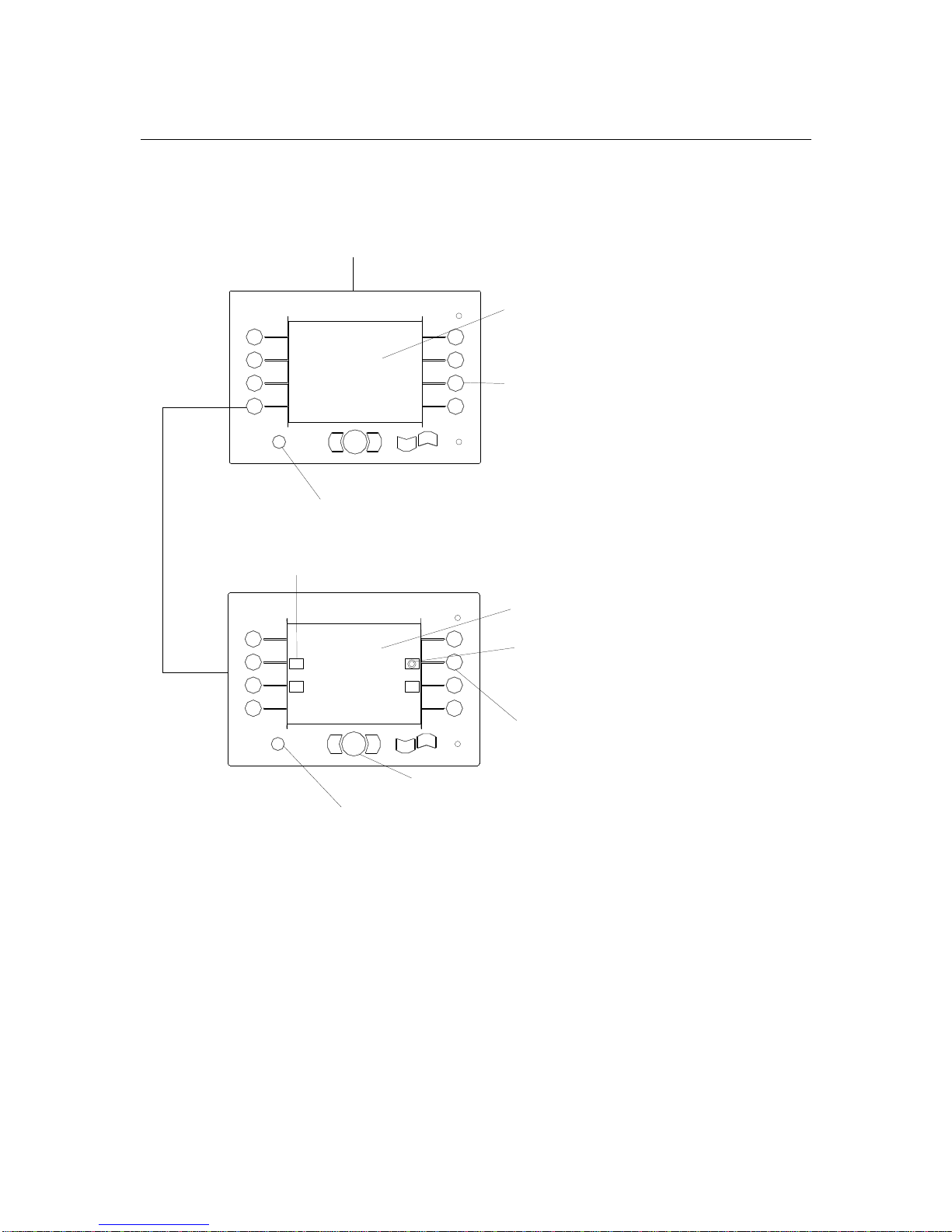
To double stack the bale, the top bale must align with the bottom bale to prevent
uneven stacking. It is recommended that setup of double stacking be done in the field
with bales. Once set, the system retains all settings until changes are made to it. The
system will retain all settings even if power to the controller (and the display unit) is
turned off.
CUSTOM 2
SET
PUSH FULL
SET BALE 1
ROW HEIGHT
SET
BALE DOWN
ESC TO RETURN/
OK TO STORE
CLAMP
ROTATE
1.55V
1.55V
1.55V
350
1.55V
1
2
3
4444
5
6
7
8
OK
ESC
CALIBRATION MODE
PUSHBACK
PART
350
SET BALE 2
ROW HEIGHT
1.55V
CUSTOM BALE SETUP
DOUBLE
STACK
CUSTOM 1
CUSTOM 2
ESC TO RETURN/OK TO STORE
CUSTOM 3
1
2
3
4444
5
6
7
8
OK
ESC
Y
CALIBRATION MODE
FUNCTION HEADING; NAME OF
FUNCTION HEADING; NAME OF FUNCTION HEADING; NAME OF
FUNCTION HEADING; NAME OF
CURRENT FUNCTION
CURRENT FUNCTIONCURRENT FUNCTION
CURRENT FUNCTION
O.K. BUTTON; PRESS TO STORE SELECTION
O.K. BUTTON; PRESS TO STORE SELECTIONO.K. BUTTON; PRESS TO STORE SELECTION
O.K. BUTTON; PRESS TO STORE SELECTION
PRESS
PRESS PRESS
PRESS
TO EXIT THIS MENU;
RETURN TO PREVIOUS MENU
FUNCTION
FUNCTIONFUNCTION
FUNCTION
STATUS; SHOWS STATUS OF FUNCTION
(DEFAULT ="NO")
FUNCTION SELECTION BUTTON;
FUNCTION SELECTION BUTTON; FUNCTION SELECTION BUTTON;
FUNCTION SELECTION BUTTON;
PRESS TO SELECT FUNCTION
PRESS TO SELECT FUNCTIONPRESS TO SELECT FUNCTION
PRESS TO SELECT FUNCTION
FUNCTION
FUNCTION FUNCTION
FUNCTION
ICON; ICON APPEARS
WHEN SELECTED
FUNCTION HEADING; NAME OF CURRENT
FUNCTION HEADING; NAME OF CURRENT FUNCTION HEADING; NAME OF CURRENT
FUNCTION HEADING; NAME OF CURRENT
FUNCTION
FUNCTIONFUNCTION
FUNCTION
FUNCTION SELECTION BUTTON; PRESS TO
FUNCTION SELECTION BUTTON; PRESS TO FUNCTION SELECTION BUTTON; PRESS TO
FUNCTION SELECTION BUTTON; PRESS TO
SELECT FUNCTION
SELECT FUNCTIONSELECT FUNCTION
SELECT FUNCTION
SENSOR
SENSOR SENSOR
SENSOR
READING
;
; ;
;
INDICATE THE
POSTION OF THE CURRENT FUNCTION
FUNCTION
FUNCTION FUNCTION
FUNCTION
NAME
;
; ;
;
NAME OF FUNCTION
SELECTED
SET PUSHER FULL = LOCATION OF PUSHER
FOR PUSHING BOTH BALES BACK
FUNCTION
FUNCTION FUNCTION
FUNCTION
ICON
;
; ;
;
ICON APPEAR WHEN
SELECTED
UUUU
P/ OPEN/ FORWARD
ARROW BUTTON;
ARROW BUTTON; ARROW BUTTON;
ARROW BUTTON;
PRESS AND HOLD TO MOVE FUNCTION
PRESS AND HOLD TO MOVE FUNCTIONPRESS AND HOLD TO MOVE FUNCTION
PRESS AND HOLD TO MOVE FUNCTION
DOW
DOWDOW
DOW
N/CLOSE/BACK
A
A A
A
RRO
W BUTTON;
W BUTTON; W BUTTON;
W BUTTON;
PRESS AND HOLD TO MOVE FUNCTION
PRESS AND HOLD TO MOVE FUNCTIONPRESS AND HOLD TO MOVE FUNCTION
PRESS AND HOLD TO MOVE FUNCTION
O.K. BUTTON; PRESS TO STORE VALUE. ONCE VALUE
O.K. BUTTON; PRESS TO STORE VALUE. ONCE VALUE O.K. BUTTON; PRESS TO STORE VALUE. ONCE VALUE
O.K. BUTTON; PRESS TO STORE VALUE. ONCE VALUE
IS STORED ICON FRON FUNCTION WILL DISAPPEAR.
IS STORED ICON FRON FUNCTION WILL DISAPPEAR.IS STORED ICON FRON FUNCTION WILL DISAPPEAR.
IS STORED ICON FRON FUNCTION WILL DISAPPEAR.
PRESS
PRESS PRESS
PRESS
TO EXIT THIS MENU;
RETURN TO PREVIOUS MENU
THESE FUNCTION
THESE FUNCTIONTHESE FUNCTION
THESE FUNCTIONS DO NOT REQUIRE SETTING.
DO NOT REQUIRE SETTING. DO NOT REQUIRE SETTING.
DO NOT REQUIRE SETTING.
VALUES ARE OBTAINED FROM MACHINE SETUP.
VALUES ARE OBTAINED FROM MACHINE SETUP.VALUES ARE OBTAINED FROM MACHINE SETUP.
VALUES ARE OBTAINED FROM MACHINE SETUP.
bühler
bühler
Page 20
bühler
4500 Square Bale Carrier
19
Manual Mode
The Manual mode allows the user to only operate one function at a time. To operate,
the user simply selects the desired function; a circular light icon will appear beside that
function. The UP/DOWN arrow keys are used to activate a function. Press ESC to
return to the main menu.
MANUAL MODE
AUTO MODE
CALIBRATION
MODE
DIAGNOSTIC
MODE
MANUAL MODE
PUSHER
TIPPING
FRAME
ROTATE ARM
LIFT ARM
CLAMP ARM
1
2
3
4444
5
6
7
8
OK
ESC
PRESS O.K. BUTTON TO
EXIT OUT OF THIS MENU
CLAMP ARM, UP ARROW = OPEN, DOWN ARROW = CLOSE
LIFT ARM, UP ARROW = ARM UP, DOWN ARROW = ARM DOWN
ROTATE ARM, UP ARROW = ROTATE RIGHT, DOWN ARROW =
ROTATE LEFT (ROTATE OVER THE DECK)
PUSHER, UP ARROW = PUSHER HOME, DOWN ARROW =
PUSHER BACK
TIPPING FRAME, UP ARROW = TIPPING UP, DOWN ARROW =
TIPPING DOWN
350
4500 SQUARE
BALE CARRIER
4500 SQUARE BALE CARRIER
READING ONLY APPEARS IF
FUNCTION IS SELECTED.
VERSION 1.0.05
1
2
3
4444
5
6
7
8
OK
ESC
VERSION 1.0.05
1
2
3
4444
5
6
7
8
OK
ESC
PRESS
PRESS PRESS
PRESS
TO EXIT THIS MENU;
RETURN TO PREVIOUS MENU
FUNCTION SELECTION BUTTON; PRESS TO SELECT FUNCTIO
FUNCTION SELECTION BUTTON; PRESS TO SELECT FUNCTIOFUNCTION SELECTION BUTTON; PRESS TO SELECT FUNCTIO
FUNCTION SELECTION BUTTON; PRESS TO SELECT FUNCTIO
N
bühler
bühler
bühler
inland
Page 21
bühler
4500 Square Bale Carrier
20
Auto Mode
The Auto mode automates the picking and stacking of bales with minimal input from the
user. Once the unit has been calibrated and the bale size selected, the user simply lets
the controller sets all functions to the ready STATE required to enter the Auto- mode.
Once in auto-mode, the user is ready to start the picking process. Loading and
unloading operations are described later in the section.
MANUAL MODE
AUTO MODE
CALIBRATION
MODE
DIAGNOSTIC
MODE
AUTO MODE
36x36
36x48
48x48
CUSTOM 1
CUSTOM 2
CUSTOM 3
AUTO MODE
BALE SIZE
DOUBLE
CLAMP
PUSHER
TIPPING
FRAME
TOTAL 2785
CURRENT 5
AUTO MODE
HOME POSITION
PUSHER
TIPPING
FRAME
ROTATE ARM
LIFT ARM
CLAMP ARM
PAUSE
O.K.TO CONFIRM SELECTION
HYDRAULIC
SYSTEM
PRESS 4 TO RESET CURRENT
THE USER CAN SWITCH
BETWEEN DOUBLE STACK "YES"
AND DOUBLE STACK "NO" BY
PRESSING THE BUTTON. IF THE
BALE SELECTED HAS ONLY
SINGLE ROW VALUES, PRESSING
THE BUTTON DOES NOT CHANGE
THE STATUS.
350
1.55V
1.55V
4500 SQUARE BALE CARRIER
1
2
3
4444
5
6
7
8
OK
ESC
VERSION 1.0.05
1
2
3
4444
5
6
7
8
OK
ESC
1
2
3
4444
5
6
7
8
OK
ESC
1
2
3
4444
5
6
7
8
OK
ESC
STACKING
OPEN
YES BALE1
36 X 36
CHOOSE FROM THE THREE (3)
PRE-PROGRAM BALES SIZES OR 3
CUSTOM BALE SIZES PROGRAM BY
THE USER TO PICK.
-PRESS THE CORRESPONDING BUTTON TO
HAVE THE COMPUTER MOVE THAT FUNCTION
TO THE READY POSITION.
-A CIRCULAR LIGHT ICON WILL APPEAR
BESIDE THE FUNCTION WHEN IT IS IN THE
READY POSTION.
-ONLY WHEN ALL FUNCTIONS ARE IN THE
READY POSITION DOES THE MENU CHANGE.
-IF A FUNCTION DOES NOT MOVE WHEN
ACTIVATED. AN UNSAFE CONDITION HAS
ARISEN, SIMPLY ACTIVATE THE NEXT
FUNCTION, THE UNSAFE CONDITION WILL
AUTOMATICALLY RESOLVE ITSELF.
bühler
bühler
bühler
bühler
Page 22
bühler
4500 Square Bale Carrier
21
Diagnostic Mode
The Diagnostic mode is used to determine errors (malfunctions) in all sensors used on
the unit. If the status of the sensor shows ERROR, this indicates that the sensor is not
working, not connected properly to the wire harness, or a defective wire harness.
MANUAL MODE
AUTO MODE
CALIBRATION
MODE
DIAGNOSTIC
MODE
DIAGNOSTIC MODE
CLAMP OPEN SENSOR
CLAMP CLOS E SENSOR
LIFT ARM S ENSOR
ROTATE SE NSOR
TIPPI NG FR AME SENSO R
MOTOR SPEE D SENSOR
O.K.
O.K.
O.K.
O.K.
O.K.
O.K.
250
0
2500
500
500
500
0
STATU S VALUE
PROXI MITY SENSO R
O.K.
ON
THIS SHOULD APPLIED FOR
POSITION SENSOR
STATUS = O.K or ERROR
VALUE = 2500 or 0
MOTOR SENSOR
STATUS = O.K. or ERROR
VALUE = 0
PROXIMITY SENSOR
STATUS = O.K or ERROR
VALUE = ON or OFF
4500 SQUARE BALE CARRIER
1
2
3
4444
5
6
7
8
OK
ESC
VERSION 1.0.05
1
2
3
4444
5
6
7
8
OK
ESC
bühler
bühler
Page 23
bühler
4500 Square Bale Carrier
22
OPERATION
CAUTION
Prior to operation, ensure that the operator has read and
understood the safety requirements of the 4500 Square Carrier. Ensure the preoperation checks have been completed prior to operation.
Attaching Bale Carrier To Tractor
CAUTION: Shut off tractor, engage parking brake and remove key before
working around hitch.
WARNING: Never attach bale carrier to rear axle or three point hitch arms.
Use only the drawbar. Make sure tractor size is adequate (100 hp or greater)
and drawbar is capable of supporting the torque whether empty or loaded.
1. CLEVIS adjustment: For most conditions, the hitch height should be adjusted on firm
level ground so that, when the TIPPING FRAME is vertical on level ground, there is
a 0” to 1” (0 to 2.5 cm) clearance at ground level. Note: For more convenient, adjust
CLEVIS so that bottom of HITCH BEAMS (at the point where the beams are joined
to each hitch bolt plate) is approximately 17” (43 cm) from the ground.
The objective of adjusting the hitch height is to bring the TIPPING FRAME firmly
on the ground when unloading, but not hard enough to transfer excessive
machine weight onto the TIPPING FRAME.
2. Using TOP WIND JACK, raise BASE HITCH
above DRAW BAR. Position tractor so that
holes are aligned. Insert pin and secure using
retaining clip. Raise JACK and hold it in the
transport position.
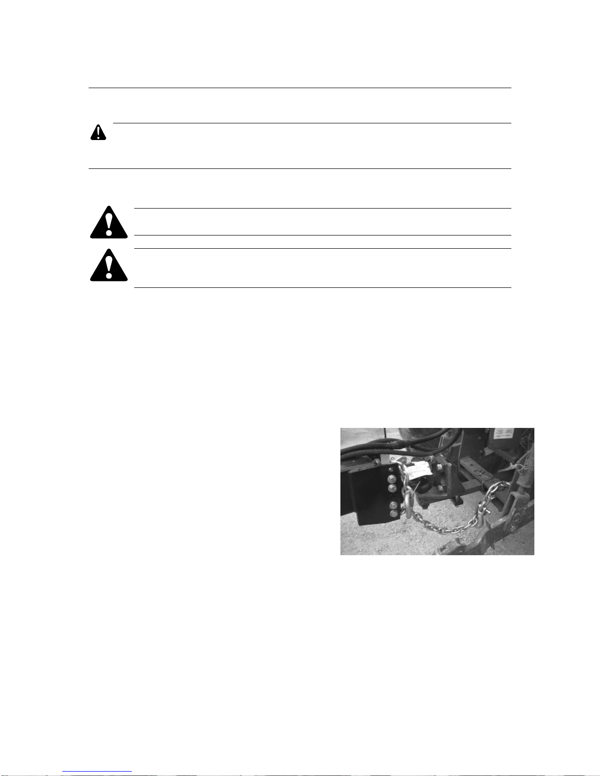
3. Route SAFETY CHAIN around the hitch clevis,
around drawbar support and back hook.
IMPORTANT: Adjust CHAIN length to remove
all slack except what is needed for turns.
4. Do not use intermediate support on drawbar as
attaching point.
5. Store SAFETY CHAIN off the ground when not in use. If safety chain is damaged in
any way, contact your dealer for a replacement.
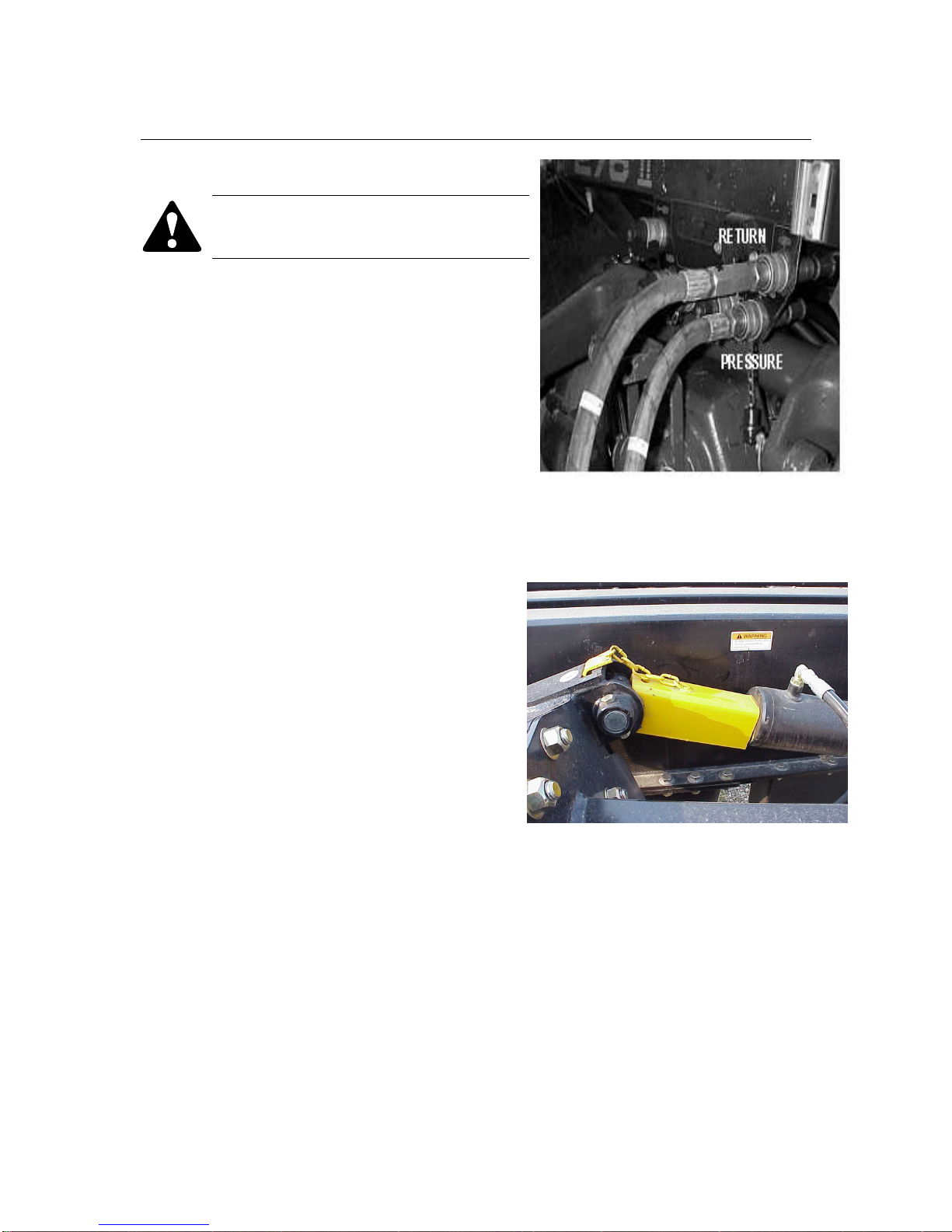
6. The pressure is the “P” port on the valve bank; return line is “T” port.
7. Connect Power/Communication harness to Cab Harness.
SAFETY CHAIN
Page 24
bühler
4500 Square Bale Carrier
23
8. Connect lighting coupler.
WARNING: Engage LIFT CYLINDER
LOCK over lift arm cylinder before
transporting.
NOTE: The LIFT CYLINDER LOCK is installed
by extending lift cylinder far enough to insert
lock, inserting lock (the notched end fits over
the cylinder’s rod pin eye and between the pin
plates), attaching chain hook to the gusset
above the pin plates, and retracting cylinder
until lock is secured in place.
LIFT CYLINDER LOCK
HYDRAULIC CONNECTION
Page 25

bühler
4500 Square Bale Carrier
24
Carrier Control Operation
WARNING: When transporting on public roadways, use amber flashers day or
night. Do not tow over 20 mph (32 km/h) when loaded.
CAUTION: Before proceeding to the field, become thoroughly familiar with the
operating controls. Although the loading arms cycling is virtually automatic, the
operator needs to be aware of some safety functions.
Built-in Safety Features
1- The Rotate Arm will not rotate toward the deck if it has not been raised above the
deck by a minimum of 1 foot.
2- Pusher will not push back toward the Tipping Frame if the Tip Frame is not at
“home” position (tipping frame is parallel to the deck).
3- Tipping frame will not lower or rise if Pusher is not in its “home” position (adjacent
to the Proximity sensor)
4- Lift Arm will not lower beyond deck height if Rotate Arm is positioned over the
deck. Rotate Arm must be rotated parallel to Lift arm (to the right) before Lift arm
can be lowered to its “home” position.
Page 26
bühler
4500 Square Bale Carrier
25
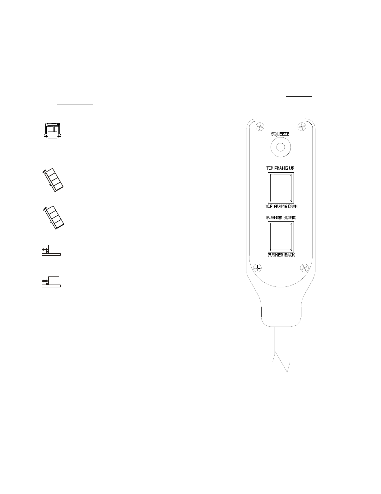
Carrier Control
The 3 BUTTON CONTROL HANDLE is supplied as a remote controller to duplicate the
SQUEEZE, PUSHER, and TIP FRAME function located on the Display Box when in
Auto mode
. The CONTROL HANDLE is fitted with one (1) plunger style switch and two
(2) momentary rocker style switches. Their function are as follows:
1
st
(top) button: Depress and hold to capture bale and
start automatic loading cycle. Press and release will
only jog the Clamp arm closer to each other. Release
switch once AUTO cycle is started (loading arm
raising).
2nd button: Depress and hold Tipping Frame Up to
raise the tipping frame vertically. Release button to
stop tipping fame motion. Tipping frame will not move
beyond set limit.
2nd button: Depress and hold Tipping Frame Down to
lower tipping frame. Release button to stop. Tipping
Frame will stop when it reaches “home” position.
3rd button: Depress “Pusher Home” and hold to move
PUSHER home. Release to stop pusher motion.
Pusher will also stop when it is in home position.
3rd button: Depress “Pusher Back” and hold to move
PUSHER back. Release to stop pusher motion.
Pusher will not travel back beyond set limit.
Page 27
bühler
4500 Square Bale Carrier
26
Automatic Sequence Adjustment
Pressure transducers, proximity sensors, and rotary position sensors are working in
concert to control the Automatic-Sequencing. The automatic loading cycle has been
tested and adjusted for 14.5 US gpm at 2500 psi at the factory. It is necessary to readjust the CLAMP OPEN and CLAMP CLOSE pressure settings compatible to your
tractor to ensure that the automatic loading/unload sequence performs correctly. Follow
the flow diagram below to perform this adjustment.
MANU AL MO DE
AUTO MODE
CALI BRATI ON
MO DE
DIAG NOSTI C
MOD E
CALI BRATI ON M ODE
CLAM P OPE N PR ESSUR E
Min
Max
DIAG NOS TIC MODE
CLAMP OPEN SENSOR
CLAMP CLOSE SENSOR
LIFT A RM SE NSOR
ROTATE SENS OR
TIPPIN G FRA ME SE NSOR
MOTOR SPEED SENSOR
O.K.
O.K.
O.K.
O.K.
O.K.
O.K.
250
0
2500
500
500
500
0
STATUS V ALUE
1
2
3
4444
5
6
7
8
OK
ESC
CALIB RATI ON MO DE
LIFT ARM
PROXIM ITY S ENSOR O.K.
ON
TIPP ING
FR AME
PUSHE R
ROTA TE AR M
CLAMP
HYDRA ULIC SYST EM
OPEN
CENTE R
CLOS E
CENTE R
ESC T O RE TURN
PRESS O.K. BUTTON TO
EXIT OUT OF THIS MENU
ESC TO RE TURN /OK T O STO RE
1.55V
4500 SQUARE
BALE C ARRIER
4500 SQUA RE B ALE C ARRIE R
NEXT PAGE
CALIB RATI ON MO DE
SET H YD
SYSTE M
SET C USTO M
BALE SIZE
S CREE N
BRIGH TNES S
PREVI OUS
P AGE
VERSI ON 1 .0.05
1
2
3
4444
5
6
7
8
OK
ESC
VERSI ON 1 .0.05
1
2
3
4444
5
6
7
8
OK
ESC
1
2
3
4444
5
6
7
8
OK
ESC
1
2
3
4444
5
6
7
8
OK
ESC
CALI BRATI ON M ODE
CLAM P CLO SE P RESSU RE
Min
Max
ESC TO RE TURN /OK T O STO RE
1.55V
1
2
3
4444
5
6
7
8
OK
ESC
1
2
3
4444
5
6
7
8
OK
ESC
SET HYD S YTEM FIRS T
1
2
3
4444
5
6
7
8
OK
ESC
CALIBR ATION MODE
bühler
bühler
bühler
bühler
bühler
bühler
bühler
bühler
inland
Page 28
bühler
4500 Square Bale Carrier
27
Adjustment for Bale Sizes
Basically, ONE adjustment will allow the carrier to load and unload most intermediate
and large square bales:
1. The LEFT GRAB ARM has two pin
locations. Select the inside location for
large bales (4’ x 4’) and the outside
location for intermediate bales.
2. An adjustable BALE STOP is provided to stop
the bale at a point where it will be centered on
the carrier deck when released. Bales longer
than 8’ (2.44 m) will require the stop to be fully
retracted.
3. The BALE EXTENSION SLEEVES need to be
adjusted about 6” (15 cm) shorter than the
intended total stack height of the bales.
BALE STOP
ADJUST BALE STOP
SLEEVE (RIGHT
SHOWN)
6”
BALE EXTENSION SLEEVES
ADJUSTMENT
INT ER ME DIA T E BALE S ETTIN
INT ER ME DIA T E BALE S ETTININT ER ME DIA T E BALE S ETTIN
INT ER ME DIA T E BALE S ETTIN
G
LAR G E BALE S E T TIN
LAR G E BALE S E T TINLAR G E BALE S E T TIN
LAR G E BALE S E T TIN
G
Page 29

bühler
4500 Square Bale Carrier
28
Two Speed Control
The PUSHER is featured to accommodate different bale types and weights. The Pusher
is driven by means of two hydraulic motors connected together. Two directional control
valves,
BACK/HOME
and
SERIES/PARALLEL
, control the motion of the two motors.
“Pusher hydraulic circuit is designed and controlled to PUSH-BACK in
PARALLEL, which means low speed and high torque”. Pushing back in parallel (low
speed, and high torque) allows handling heavy wet bales.
If after five seconds at low speed the pusher has not moved, a flashing message
“DECK FULL” will appear on the display unit indicating that the deck is full and
unloading procedure can take place.
Pre-start Check List
Check the following daily before operating the bale carrier. This should ensure that the
bale carrier functions properly and avoid breakdowns and accidents.
1. Check that all component and assemblies are complete and that all shields are in
place.
2. Check for missing fasteners and replace if necessary (it is normally not
necessary to retighten fasteners on a daily basis).
3. Tighten loose wheel bolts, especially if tire has been removed recently (wheel
bolts do not normally require daily inspection).
4. Clean bale carriers of any foreign material that may have accumulated from
previous runs, especially the areas where sensors are located. The automatic
loading cycle will not function properly if there is interference in sensor readings.
5. Lubricate all points requiring daily lubrication.
6. Check and maintain proper tire pressure.
7. Ensure that the bale carrier has been correctly set for the intended bale size (see
the section “Adjusting for Bale Size” in this manual).
8. Ensure that the automatic loading cycle has been adjusted for the intended
hydraulic flow rate and pressure, especially if a different tractor is used (see the
section “Automatic Sequencing Adjustments” in this manual).
Page 30

bühler
4500 Square Bale Carrier
29
Loading Operations
WARNING: Stay away from lift arm or tipping frame when operating to
prevent crushing. Keep others away.
DANGER: Stay away from overhead power lines when rising lift arm or
tipping frame to prevent electrocution.
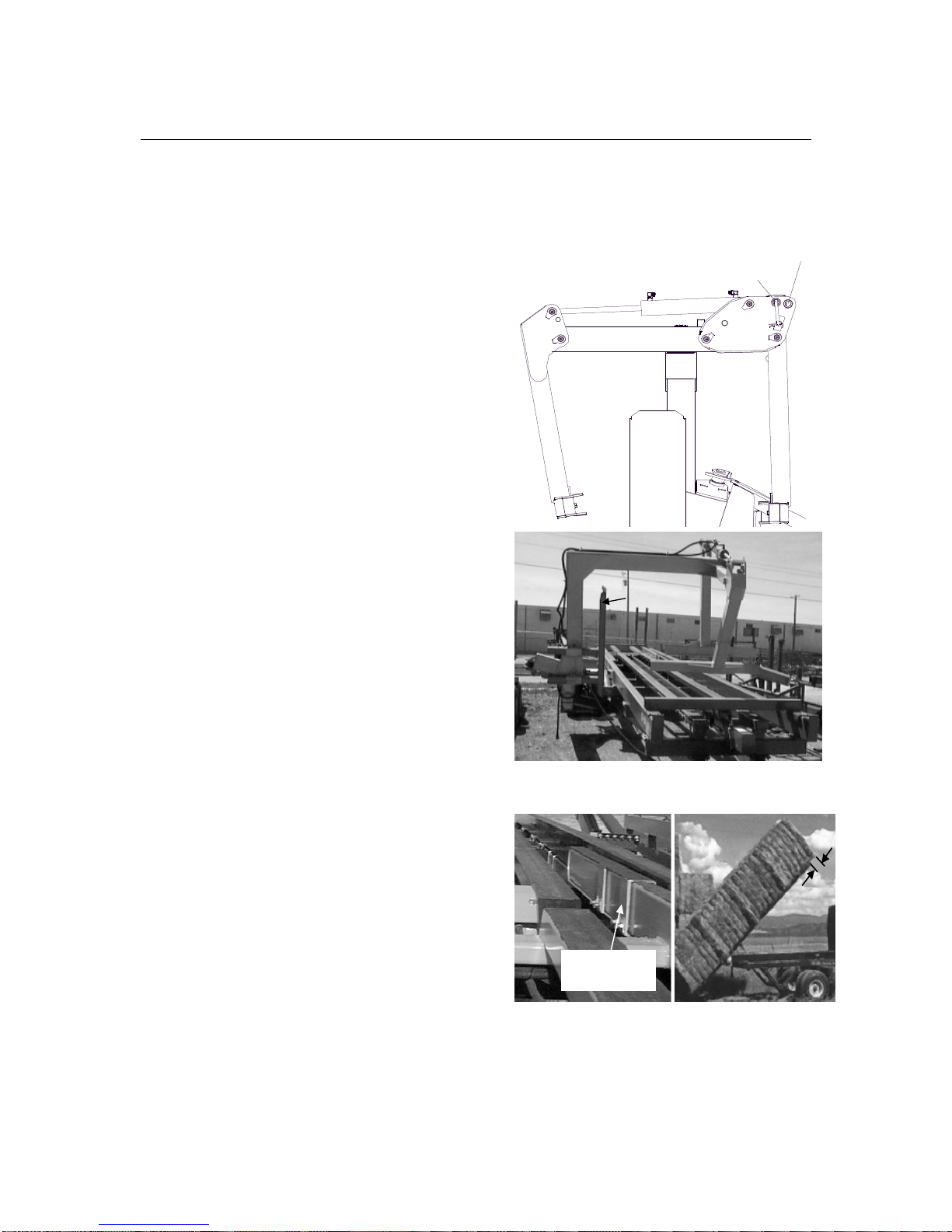
Initial Preparation
To move arm from transport to operational position follow the flow diagram below:
1. To raise the lift arm up, press and hole the Up arrow key until the Transport lock
no longer touches the cylinder base, release button.
2. Remove Transport Locker Assembly and stow as follows:
MANUAL MODE
AUTO M ODE
CALIBR ATION
MODE
DIAGNO STIC
MODE
MANUAL MODE
PUSHER
TIPPIN G
FRAM E
ROTATE ARM
LIFT A RM
CLAMP ARM
1
2
3
4444
5
6
7
8
OK
ESC
PRESS O.K. B UTTON TO
EXIT O UT OF THIS M ENU
1.55V
450 0 S QUAR E
BALE CAR RIE R
4500 S QUARE BALE C ARRIER
READI NG ON LY AP PEARS IF
FUNC TION IS SELEC TED.
VERSIO N 1.0. 05
1
2
3
4444
5
6
7
8
OK
ESC
VERSIO N 1.0. 05
1
2
3
4444
5
6
7
8
OK
ESC
bühler
inland
bühler
bühler
LIFT CYLINDER LOCK (IN STORAGE)
Page 31

bühler
4500 Square Bale Carrier
30
Initial Loading Operation
Follow the flow diagram to set machine for loading operation. IMPORTANT: Do not
attempt to load two rows of large (4’ x 4’ x 8’) bales. Doing so would exceed the gross
vehicle weight of the carrier.
MANUAL MODE
AUTO MO DE
CALIBRA TION
MODE
DIAGNOS TIC
M ODE
AUTO MO DE
36x36
36x48
48x48
CUSTOM 1
CUSTOM 2
CUSTOM 3
AUTO MOD E
BALE SIZE
DOUBLE
CLAMP
PUSHER
TIPPING
FRAME
TOTAL 2785
CURRENT 5
AUTO MODE
HOME POSITION
PUSHER
TIPPING
FRAME
ROTATE ARM
LIFT ARM
CLAMP ARM
1
2
3
4444
5
6
7
8
OK
ESC
PAUSE
O.K.TO CONFIRM SELECTI ON
HYDRAULI C
SYSTEM
PRESS 4 TO RESE T CURRE NT
THE USER CAN SWITCH BETWEEN
DOUBLE STACK "YES" AND
DOUBLE STACK "NO" BY
PRESSING THE BUTTON. IF THE
BALE SELECTED HAS ONLY
SINGLE ROW VALUES, PRESSING
THE BUTTON DOES NOT CHANGE
THE STATUS.
PRESS O.K. BUTTON TO
EXIT OUT OF THIS MENU
350
1.55V
1.55V
4500 SQUARE
BALE CARRIER
4500 SQ UARE BAL E CARRI ER
THESE READING ARE ALWAYS
SHOWN
VERSION 1.0.05
1
2
3
4444
5
6
7
8
OK
ESC
VERSION 1.0.05
1
2
3
4444
5
6
7
8
OK
ESC
1
2
3
4444
5
6
7
8
OK
ESC
1
2
3
4444
5
6
7
8
OK
ESC
STACKING
OPEN
YES BAL E1
36 X 36
bühler
bühler
bühler
bühler
bühler
inland
Page 32

bühler
4500 Square Bale Carrier
31
1. After selecting bale size, the “Auto Home Position” screen appears. This menu
screen is designed to automatically set (“activate”) all functions to the ready state
needed for loading operation. By pressing the button corresponding to each
function, the Controller will automatically activate that function. When a function
is in the ready position (activated) a circular icon will appear beside that function.
If a function has not been activated when the corresponding button is pressed,
this indicates that an unsafe condition exists. The safety protocol has prevented
the function from operating. For example, Lift Arm down cannot be activated until
the Rotate Arm has rotated away from the deck. The menu screen will change
when all functions are in the ready position (activated).
2. The next screen is the “Auto Mode” screen, this indicates that all functions are
ready and loading operation can begin. Loading operation can be started with the
“CLAMP” button located on the Display unit or with the “SQUEEZE” button
located on the hand held pendent. Pressing and release to jog the clamp arm
together. Press and hold to activate the Auto cycle. Once the Lift Arm rises,
release Squeeze button.
Loading Operation
1. Approach the bale from the narrow side in a straight line parallel to the bale
(baling direction), not at an angle. When rear of bale strikes BALE STOP, stop
tractor and depress and hold “CLAMP” button (or the 1st button on the 3BUTTON CONTROL HANDLE) until ARM begins to rise, release switch. The
automatic loading cycle is now engaged. Lift arm should continue to rise to Row
1 Bale height location, SWING ARM rotates 90° to le ft, and bale is released onto
deck. SWING ARM rotates forward (right), and Lift Arm goes down to the loading
position. Simultaneously, the Pusher will automatically push the released bale
back to a preset location. Proceed with the next bale. You are now ready to load
the next bale.
2. If Double Stacking: As mentioned above the Pusher will automatically push the
first bale back to a predetermined location, approximately 6” to 12”. Then, the
DOUBLE STACKING indicator will indicate BALE2. Load the second bale as in
step 1 noting that the LIFT ARM goes UP higher than in first step (higher than the
bale that is already on the deck). SWING ARM rotates 90° with the second bale
coming in perfect alignment with the first bottom bale. The bale is released on top
of the bottom bale. The PUSHER will push back both bales, enough to clear the
deck for the next set of bales.
DIRECTION OF APPROACH
Page 33

bühler
4500 Square Bale Carrier
32
NOTE: When four bales (if loading a single layer) are picked up (or two layers with five
intermediate-sized bales each), push the entire load back against the TAIL STOPS at
the back of TIPPING FRAME to minimize hitch load. This can be done either using the
buttons on the Display unit or the handheld control handle. You DO NOT have to exit
the “Auto Mode” to perform these functions.
1. Continue loading bales until bale carrier is fully loaded. When the last bale is
loaded, you will see the DECK FULL message flashing on the display unit
indicating that you are ready for unloading.
Once the loading techniques are mastered, loading can be done on-the-go. Tractor
speed should not exceed 10km/hr when approaching the bale. High speeds result in
damage to the bale carrier.
Unloading Operation
WARNING: Stay away from lift
arm or tipping frame when
operating to prevent crushing.
Keep others away.
DANGER: Stay away from overhead
power lines when rising lift arm or
tipping frame to prevent
electrocution.
DANGER: Stay away from bale
stack when unloading. Bales
can tip over. Keep others away.
Stacking should be attempted
on level ground only.
STAY AWAY FROM OVERHEAD POWER
LINES
STAY AWAY FROM
BALE STACK
Page 34

bühler
4500 Square Bale Carrier
33
The most stable bale stack is achieved by
stacking bales with the most dense side
facing outward. Gravity virtually assures
that as bales are being formed in the baler
heavier particles end up in the bottom half
of the bale, making the lower half denser
(heavier) than the top. The lighter side of
the bale may “sag” over time. As a result,
stacked bales being leaned toward the
stack.
Starting A Stack
If possible, start a stack less than full
height for the first load to allow bales to
support each other. This is best achieved
by loading only 5 bales for the first load
(i.e. load 3 bales first, push these all the
way to the rear, then load two additional
bales. Unload the first stack of 3 bales,
drive forward, and then unload the
remaining stack of 2 bales against the first
stack). Lay the main stack from the
opposite end to the direction of the initial
stack.
NOTE: The unloading procedure outlined
below can be done in the Auto Mode.
1. Press and hold TIP FRAME UP until
TIPPING FRAME is vertical.
2. Slowly drive the tractor forward until
the stack eases off the TAIL STOPS
and onto the ground.
3. Second Stage Unloading: Drive the
tractor forward until there is enough
room to safely lower the TIPPING
FRAME onto the carrier deck. Depress
and hold TIP FRAME DOWN until
TIPPING FRAME is lowered fully onto
carrier deck. Depress and hold
PUSHER BACK. Release switch when
rear bale hits TAIL STOPS. Return
pusher to the front by pressing and
holding the PUSHER HOME button.
RAISE TIPPING FRAME
LOWER TIPPING FRAME
INITIAL
STACK
MAIN
STACK
BALE STACKS
Page 35

bühler
4500 Square Bale Carrier
34
4. Raise the TIPPING FRAME when the
pusher is at the home position and
repeat the unloading procedure by
placing the second stack as close as
possible to the first.
NOTE: TIPPING FRAME will go about 5°
past vertical position when TIPPING
CYLINDERS are fully extended. This
feature is useful to straighten out a leaning
stack.
Transporting Carrier
1. Use tractor with a minimum of 100 hp
and adequate braking capacity to
safely control 25,000 lbs. (11,340 kg)
GVW trailing load to tow the bale
carrier.
2. The towing unit should weigh 16,700
lbs. (7575 kg) or approximately 67% of
the carrier's GVW.
3. Do not tow over 20 mph (32 kph) when
loaded.
4. Turn on flashing lights when
transporting on public roadways.
5. Obey local regulations regarding road
transport.
6. Raise lift arm to transport position and
engage LIFT CYLINDER LOCK over
lift arm cylinder before transporting.
7. If the bale carrier is equipped with the
optional second layer kit, close the rear
stack stabilizer sufficiently to reduce its
width prior to transporting.
LIFT CYLINDER LOCK
Page 36

bühler
4500 Square Bale Carrier
35
MAINTENANCE
WARNING:
Place all tractor controls in neutral, stop engine, set
parking brake, remove ignition key and wait for all moving parts to stop
before servicing, adjusting or repairing bale carrier.
The following sections explain regular inspections and adjustments.
IMPORTANT: Service intervals should be increased when operating in extreme or
difficult conditions.
Fasteners
The tables below list the correct torque values for various bolts and cap screws used on
the bale carrier. Tighten all bolts to specified values unless otherwise noted.
BOLT TORQUE
SAE 2 SAE 5 SAE 8 L9
BOLT
DIAMET
ER
"A"
lb-ft N.m lb-ft N.m lb-ft N.m lb-ft N.m
1/4" 6 8 9 12 12 17 10 13
5/16" 10 13 19 25 27 36 19 26
3/8" 20 27 33 45 45 63 30 41
7/16" 30 41 53 72 75 100 55 75
1/2" 45 61 80 110 115 155 85 115
9/16" 70 95 115 155 165 220 120 163
5/8" 95 123 160 215 220 298 170 231
3/4" 155 225 290 390 400 540 265 360
7/8" 170 230 420 570 650 880 475 645
1" 225 305 630 850 970 1320 550 746
LOCATION
lb-ft
N.m
WHEEL HUB BOLTS 125 170
HITCH MOUNT 1-1/4” HEX NUT 225 305
ALL CARRIAGE BOLTS 33 45
Check all bolts for tightness after the first 10 hours of operation and every 50 hours
thereafter.
Periodically inspect for broken or missing fasteners. Replace with those designated in the
“Parts” section of this manual.
Page 37

bühler
4500 Square Bale Carrier
36
Hydraulic System
WARNING: To prevent serious injury or death from high-pressure fluid:
•
Relieve pressure on system before repairing, adjusting or
disconnecting hydraulic components.
•
Wear proper hand and eye protection when searching for leaks. Use
wood or cardboard instead of hands.
•
Seek immediate medical attention if injured by hydraulic fluid
piercing the skin.
1. Keep the hydraulic components clean to prevent contaminants from entering the
system.
2. Regularly check the fluid level in the tractor reservoir and follow the maintenance
procedures in the tractor Operator’s Manual.
3. Regularly inspect cylinders, hoses and fittings for leaks, crimps and abrasions or
other signs of wear and tear or impending failure.
4. Replace cut, worn or crimped hoses and metal lines.
5. Check that all components are in good working condition. Tighten any loose
components.
6. Avoid makeshift repairs to the hydraulic system such as clamping or taping fittings or
hoses. The system operates at high pressure and failure of such repairs can happen
suddenly and without warning resulting in unsafe or hazardous conditions.
7. Hydraulic lines and cylinders must be free of air to function correctly. Air can be bled
from the hydraulic system by parking the bale carrier in the field position on a level
surface with the tractor engine running and cycling the system.
Chain/Sprocket
1. Inspect and tighten chain and sprockets after
the first 10 hours and every 50 hours
thereafter.
2. The PUSHER ROLLER CHAIN can be
tightened by turning SPROCKET TENSION
BOLT clockwise (it should be tightened until
there is little or no slack in the CHAIN). If no
more adjustment is possible, shorten
ROLLER CHAIN by removing one link.
SPROCKET TENSION BOLT
Page 38

bühler
4500 Square Carrier
37
3. Apply a SAE light machine oil (or equivalent) with a brush to ROLLER CHAIN
several times during the season and especially before out of season storage.
4. Repaint top of CARRIER BEAMS regularly with Slip Plate
TM
to reduce friction,
especially when handling heavier bales.
Wheel/Tires
Check HUB BOLTS regularly for tightness.
1. Ensure that DUST CAPS are firmly in place.
2. Check tires pressure regularly: 90 psi (620
kPa).
3. The wheel bearings should be inspected and
re-packed annually with SAE multi purpose
type grease. When reinstalling the wheels,
the HUB BOLTS should be torque to 125 ftlbs. (note: the valves should be facing away
from the HUBS). A thread-locking compound
such as Locktite 271 is recommended for the
HUB BOLTS.
DUST CAP
BOLTS
CHECK TIRE
PRESSURE
WHEELS AND TIRES
Page 39

bühler
4500 Square Carrier
38
Lubrication
1. All grease fittings should be lubricated
before operating the bale carrier at the start
of the season and daily during the season.
Use a SAE multi purpose lubricant or
equivalent. There are 22 fittings to lubricate:
- At both ends of each HYDRAULIC
CYLINDER - 10 fittings (A).
- At position where SWING ARM is joined
to MAIN ARM - 4 fittings (B).
- At position where GRAB ARMS are joined
to SWING ARM - 2 fittings (C).
- On each AXLE BEARING – 4 fittings (D).
- At position where TIPPING FRAME is
joined to FRAME - 2 fittings (E).
LUBRICATION POINTS
A
A
A
A
A
A
A
A
E
E
C
D
D
B
A
C
Page 40

bühler
4500 Square Carrier
39
Special Care Condition
To assure trouble free service, keep the machine free of any build up hay or straw,
especially areas where the sensors are located.
Follow the lubrication instructions regularly as indicated.
To prevent rust on the CARRIER BEAMS, repaint regularly with graphite paint such as
Slip PlateTM. This should be done especially before placing machine in storage and
several times during the season.
Storage
End of Season
1. Check for worn or damaged parts and replace, if necessary. To avoid costly delays,
please contact your dealer for service parts long enough before starting the next
season.
2. Store the bale carrier in a clean, dry, sheltered area.
3. Replace all missing or broken bolts with those designated in the “Parts” section of
this manual.
4. Clean the bale carrier. Dirt draws moisture that rusts metal.
5. Repaint chipped or worn areas. Paint is available from your dealer.
6. Clean ROLLER CHAIN and brush with SAE light machine oil (or equivalent) to
prevent rust.
7. Repaint the top of the CARRIER BEAMS with graphite paint such as Slip Plate
TM
to
prevent rust.
Start of Season
1. Clean and inspect the bale carrier when taking it out of storage. Ensure that the bale
carrier is in optimum condition at the start of the season in order to reduce chances
of costly breakdown.
2. Clean and inspect ROLLER CHAIN for excessive wear or stiffness. Check for proper
adjustment and alignment.
3. Lubricate the entire bale carrier. Ensure that all grease fittings are in place and
taking grease properly.
4. Inspect and repack wheel bearings with a SAE multi purpose type grease.
Page 41

bühler
4500 Square Carrier
40
5. Check that tires are properly inflated.
6. Check all bolts for tightness. Replace lost or worn bolts.
7. Replace and secure safety shields. Review safety regulations.
8. Operate the bale carrier for a short time. Check that all moving parts are operating
freely and that automatic loading cycle is operating as expected. Check for hydraulic
leaks.
9. Review the Operator’s Manual.
During the Season
1. At the end of each day, park the bale carrier in a clean, dry, sheltered area.
2. Lubricate areas requiring daily lubrication.
3. Remove any build up hay or straw, especially in areas where sensors are located.
Stack Storage
1. Stacks should be placed in an open, flat and well-drained area. The area should
have safe and easy access for bale handling and transportation equipment.
WARNING: Take all necessary steps to prevent children or unauthorized
personnel from entering storage area. Keep a fire extinguisher handy
because of the flammable nature of the baled material.
2. Use caution when retrieving stacks or bales. Do not extend bale-lifting equipment
beyond its capacity or move more bales than the equipment is designed for.
Page 42

bühler
4500 Square Carrier
41
APPENDIX LIST
Description Appendix Page
Assembly Instructions……………….…….……………………….. A 42
Hydraulic Assembly……………...…………………………………. B 57
Electrical Assembly……………...…………………………………. C 70
General Assembly……………………………………….…………. D 80
Troubleshooting Guide…………………………………………….. E 88
Page 43

bühler
4500 Square Carrier
42
APPENDIX A
Assembly Instructions
Table of Contents
Description Page
Carrier Final Assembly….…………………………………………………………..
44-56
Page 44

bühler
4500 Square Carrier
43
CAUTION
Make sure area is clear of obstructions, well lit, and has
sufficient room for safe assembly.
CAUTION
Ensure the 4500 Square Carrier tires and hitch are securely
block. Otherwise, verify the 4500 Square Carrier is properly coupled to the drawbar on a
tractor with a minimum of 25,000 LB (11340 kg).
NOTE:
Hydraulic Assembly methods and layouts are common to the right and left
sides. Only one side of each component is shown in this manual.
CAUTION
Stay clear of the arms when testing a finished assembly.
Ensure during assembly to keep your entire body out from underneath parts that are
being attached to the main frame.
Page 45

Carrier Final Assembly, Base Frame (Part # I20090)
4500 Square Carrier
31
9
111212
14 12 12
13
10
3
2
15
8
7
6
4
5
1
16
18
1717
16
TYP
13
Page 46

bühler
4500 Square Carrier
45
Carrier Final Assembly, Base Frame (Part # I20090)
ITEM QTY PART NUMBER DESCRIPTION
1 1 C2700-00 MAIN FRAME ASSY
2 1
I20087
HITCH WELDMENT RH
3 1
I20086
HITCH WELDMENT LH
4 1 C2721-00 AXLE BEAM
5 1 C2719-00 REAR CYLINDER MOUNT
6 2 A7004-00 TANDEM AXLE/4000-2500 ASSY
7 1 C2705-00 SECOND CROSS MEMBER ASSY
8 1
I20089
FRONT CROSS MEMBER WELDMENT
9 1 814352 HITCH BASE
10 1 B2363-00 HOSE HOLDER, YELLOW
11 3 9846394 BOLT HEX 0.750NC X 7LG GR8 PL
12 8 813590 WASHER 0.781ID X 1.25OD FL PL
13 4 813648 NUT LOCK (STEEL)0.750NC GRC PL
14 1 967286 BOLT HEX 0.750NC X 2.00 GR8 PL
15 1 813685 SCREW JACK 5 TON
16 86 967274 BOLT HEX 0.500NC X 1.50 GR8 PL
17 172 84048 WASHER 0.500 FLAT SAE Bs PL
18 86 813663 NUT LOCK (STEEL) 0.500NC GRCPL
Page 47

A
DETAIL A
11.0
14
15
19
1
17 12 12
18
20
2
1313
5
6
7
4
3
9
8
10
1112
13
TYP
TYP
TYP
TYP
WRAP SAFETY CHAIN AROUND LH HITCH BEAM.
SECURE WITH WIRE TOPE.
MAKE SURE TO PRVIDE PROTECTIVE SHEET ON
HITCH BEAM TO PREVENT DAMAGE TO PAINT.
16
Carrier Final Assembly, Motors and Chain Guide (Part # I20090)
4500 Square Carrier
31
Page 48

bühler
4500 Square Carrier
47
Carrier Final Assembly, Motors and Chain Guide (Part # I20090)
ITEM QTY PART NUMBER
DESCRIPTION
1 1
I20091
CHAIN GUIDE RAIL WELDMENT
2 2
I100180
U-BOLT VALVE MOUNT 4500
3 1 E2795-00 DECAL MOUNT SMV
4 1 967066 DECAL SLOW MOVING VEHICLE SIGN
5 4 81525 BOLT HEX 0.250NC X 0.750 GR5 PL
6 4 812624 WASHER 0.250 SAE FLAT BS PL
7 4 84498 NUT LOCK (STEEL) 0.25NC GRB PL
8 1 813660 MOTOR 22.2 CU IN
9 1 814106 MOTOR 22.2 CU IN W/SENSOR
10 1 C2770-00 REAR SPROCKET ASSEMBLY
11 4 813686 BOLT HEX 0.500NC X 1.75 GR8 PL
12 20 84048 WASHER 0.500 FLAT SAE Bs PL
13 8 813663 NUT LOCK (STEEL) 0.500NC GRCPL
14 1 A2700-46 SPROCKET ASSEMBLY
15 1 C2768-00 SPROCKET ADJUSTING BOLT FRONT 1NC
16 1 813641 CHAIN SAFETY 40M GVW
17 8 81620 BOLT HEX 0.500NC X 1.25GR5 PL
18 8 812364 NUT LOCK (STEEL) 0.500NC GRB PL
19 1 84051 NUT HEX JAM 1.00NC GR2
20 1
I100202
MOUNTING PLATE
Page 49

A
DETAIL A
1
2
13
12
12
11
10
9
9
8
4
7
9 8
6 14
7
USED ONLY FOR
REAR CROSS MEMBERBOLT PLAT (INE2700-23)
T Y P.
T Y P.
T Y P.
6
7
5
Carrier Final Assembly, Beams and Track (Part # I20090)
4500 Square Carrier
31
3
Page 50

bühler
4500 Square Carrier
49
Carrier Final Assembly, Beams and Track (Part # I20090)
ITEM QTY PART NUMBER
DESCRIPTION
1 1
I20079
LEFT CARRIER BEAM 4500
2 1
I20078
RIGHT CARRIER BEAM 4500
3 1 C2706-00 LEFT SLIDER BEAM
4 1 C2766-00 RIGHT SLIDER BEAM
5 1 E2776-00 REAR SPROCKET SHIELD
6 16 86170 BOLT HEX 0.375NC X 1.00 GR5 PL
7 16 812363 NUT LOCK (STEEL) 0.375 GRB PL
8 49 967274 BOLT HEX 0.500NC X 1.50 GR8 PL
9 98 84048 WASHER 0.500 FLAT SAE Bs PL
10 49 813663 NUT LOCK (STEEL) 0.500NC GRCPL
11 10 967285 BOLT HEX 0.625NC X 1.75 GR8 PL
12 20 812639 WASHER 0.625 SAE FLAT BS PL
13 10 812482 NUT LOCK (STEEL) 0.625NC GRB PL
14 4 81570 WASHER 0.375 FLAT ST HS PL
Page 51

A
DETAIL A
B
DETAIL B
3
4
20
15
14
13
19
5
2
1
10
11
T Y P.
T Y P.
25
12
98
6
T Y P.
T Y P.
T Y P.
T Y P.
T Y P.
7
8
T Y P.
21
21
C
DETAIL C
26
23
24
22
D
DETAIL D
26
27
B
B
B
B
B
18
17 17
16
Final Assembly (Part # I20090), Pusher and Tipping Frame
4500 Square Carrier
31
Page 52

bühler
4500 Square Carrier
51
Final Assembly (Part # I20090), Pusher and Tipping Frame
ITEM QTY PART NUMBER
DESCRIPTION
1 2
I20094
PIVOT TUBE WELD'T
2 1
I20076
PIVOT CONNECTOR TUBE WELD'T
3 1
I20077
TIPPING FRAME ASSY 4500
4 1 C2736-00 LH BALE EXTENSION SLEEVE
5 1 C2737-00 RH BALE EXTENSION SLEEVE
6 4 E2723-00 TAIL STOP
7 4 812768 BOLT HEX 0.500NC X 1.25 GR8 PL
8 8 813663 NUT LOCK (STEEL) 0.500NC GRCPL
9 4 813686 BOLT HEX 0.500NC X 1.75 GR8 PL
10 8 86171 BOLT HEX 0.375NC X 1.25 GR5 PL
11 8 812363 NUT LOCK (STEEL) 0.375 GRB PL
12 8 984077 NUT HEX JAM 0.500 NC GR2PL
13 1
I20073
PIVOT HOLDER RH
14 2 E2791-00 SPLIT BUSHING UHMW
15 1 C2875-00 PIVOT HOLDER LH
16 24 813729 BOLT HEX 0.625NC X 1.79 L9 BOLT
17 48 813730 WASHER FL 0.325 L9 PL
18 24 813731 NUT LOCK 0.625NC PL
19 1
I20088
BALE PUSHER COMPLETE ASSY 4500
20 1 52959-648 CHAIN ROLLER #80
21 2 813643 CONNECTOR LINK HD C2080
22 1 C2853-00 FRONT SPROCKET SHIELD
23 4 81549 BOLT HEX 0.313NC X 0.75 GR5PL
24 4 812362 NUT LOCK (STEEL) 0.313NC GRBPL
25 8 813547 SET SCREW SQHDCUP 0.500 NC
26 2 814481 PROXIMITY SENSOR HARNESS ASSY
27 1 83000031 PROXIMITY SENSOR BRACKET, TIPPING
Page 53

A
DETAIL A
B
DETAIL B
5
4
3
2
1
12
9
10
11
10 9
13
10
14
8
C
DETAIL C
6
7
16
2019
22
17
18
21
15
15
Final Assembly (Part # I20090), Tipping Frame and Arm
4500 Square Carrier
31
Page 54

bühler
4500 Square Carrier
53
Final Assembly (Part # I20090), Tipping Frame and Arm
ITEM QTY PART NUMBER
DESCRIPTION
1 2 25106 CYL 3.5 X 36.0 INL
2 4 812363 NUT LOCK (STEEL) 0.375 GRB PL
3 4 811795 BOLT HEX 0.375NC X 2.00 GR5 PL
4 2 E2912-00 PIN / HYD. CLY
5 2 C2893-00 HYD CYL PIN
6 1 24879 CYL 4.0 X 18.0 INL
7 1 B2724-00 END CAP LH / PIVOT ARM
8 2 967285 BOLT HEX 0.625NC X 1.75 GR8 PL
9 2 81626 BOLT HEX 0.500NC X 2.75 GR5PL
10 10 812364 NUT LOCK (STEEL) 0.500NC GRB PL
11 1 E2733-00 MAIN CLEVIS PIN
12 1 E2732-00 CYL PIN MAIN ARM LIFT
13 4
I100225
STOP PLATE UHMW PIVOT ARM
14 8 87553 BOLT HEX 0.500NC X 1.75 GR5 PL
15 6 811414 ELBOW 90 3/4 MORB X 3/4 MJIC
16 1 83000028 ROTARY SENSOR
17 1 83000037 ROTARY SENSOR LEVER WELD'T
18 1 83000038 RIVET, FLAT HEAD (STEEL)
19 2 44510 SCREW, M5 X 16
20 2 86511996 NUT LOCK (NYLON) M5 CLASS 8 PL
21 1 83000033 ROTARY SENSOR LINK, LIFT ARM
22 1 50714 SET SCREW, HEX SKT
Page 55

A
DETAIL A
B
DETAIL B
C
DETAIL C
34
38
35
36
32
30
37
3940
28
2727
26
7
6 5
4
7
20
6
5
4
18
19
41
11
24
25
31
29
19
12
7
6
5
4
2
23
24
24
25
13
1
8
9
10
11
4
5
6
7
14
19
21
22
16
15
17
3
3
T Y P.
BOTH CYLINDERS
T Y P.
T Y P.
T Y P.
T Y P.
T Y P.
B
B
B
43
30
42
33
Final Assembly (Part # I20090), Lift- and Rotating Arm
4500 Square Carrier
31
Page 56

bühler
4500 Square Carrier
55
Final Assembly (Part # I20090), Lift - and Rotating Arm
ITEM QTY PART NUMBER DESCRIPTION
1 1
I20067
PIVOT ARM ASSEMBLY 4500
2 1
I20060
LIFT ARM WELD'T
3 2 24968 CYL 3.0 X 16.0 ASSY INLAND
4 7 811792 BOLT HEX 0.375 X 1.50 GR5 PL
5 7 81593 WASHER 0.375 LOCK PL
6 7 114825 PIN CAP 1.75ODX0.41IDX0.25 PL
7 4
I20070
PIN ASSY RH GRAB ARM 4500
8 1
I20075
PIVOT PIN ASSEMBLY 4500
9 1
I100222
CAP BOLT PIVOT PIN ASSEMBLY
10 1 81701 WASHER LOCK 0.750 PL
11 2 813515 BOLT HEX 0.750NC X 2.50 GR8 PL
12 2 814355 SHIM 2.0ID X 2.75OD X 0.188 POLYU
13 1 26026 HUB CAP 8" CHROME
14 2
I20069
LOCKING PIN BALE STOP 4500
15 1
I20062
RH GRAB ARM ASSY 4500
16 1
I20064
LH GRAB ARM ASSY 4500
17 1
I20066
GRAB ARM JOINT 4500
18 1
I20072
PIN ASSY REMOVEABLE 4500
19 4 12779 HAIR PIN
20 3
I20071
PIN ASSY LH GRAB ARM 4500
21 1
I20065
LH GRAB FINGER ASSY 4500
22 1
I20063
RH GRAB ARM ASSEMBLY 4500
23 27 84467 BOLT HEX 0.750NC X 2.00 GR5 PL
24 56 84050 WASHER 0.750 SAE FLAT BS PL
25 28 813648 NUT LOCK (STEEL)0.750NC GRC PL
26 4 84277 BOLT HEX 0.500NC X 1.50 GR5PL
27 8 84048 WASHER 0.500 FLAT SAE Bs PL
28 4 812364 NUT LOCK (STEEL) 0.500NC GRB PL
29 1 C2863-00 CYLINDER LOCK HOLDER
30 3 81922 NUT LOCK (NYLON) 0.25NC GR B PL
31 1 C2862-00 CLYINDER LOCK
32 1 81525 BOLT HEX 0.250NC X 0.750 GR5 PL
33 2 84062 GREASE FITTING 0.250NF STRAIGHT
34 1 83000028 ROTARY SENSOR
35 1 83000037 ROTARY SENSOR LEVER WELD'T
36 1 83000034 ROTARY SENSOR LINK, SWING ARM
37 1 83000038 RIVET, FLAT HEAD (STEEL)
Page 57

bühler
4500 Square Carrier
56
38 1 00050714 SET SCREW, HEX SKT
39 2 00044510 SCREW, M5 X 16
40 2 86511996 NUT LOCK (NYLON) M5 CLASS 8 PL
41 4 811414 ELBOW 90 3/4 MORB X 3/4 MJIC
42 1
I100221
LIFT ARM SENSOR HOLD DOWN
43 2 81529 BOLT HEX 0.250NC X 1.5LG GR2 PL
Page 58

bühler
4500 Square Carrier
57
APPENDIX B
Hydraulic Assembly
NOTE: 1)
Seal Kits and Service Parts are only listed in the parts lists and are
not indicated on the illustrations.
Table of Contents
Description Page
Carrier Hydraulic Assembly. ………………………………………………………
58-65
Valve Bank Assembly………………………………………………………………
66
Hydraulic Pressure and Return Line Assembly…….…………………………...
67-68
Valve Bank Hydraulic Schematic………………………………………………….
69
Page 59

A
DETAIL A
13
12
10
11
B
DETAIL B
3
1
C
DETAIL C
12
11
15
14
D
DETAIL D
4
56
9
8
2
7
RETURN
PRESSURE
16
17
1918
Carrier Hydraulic Assembly (Part # I20090), Main Lines
4500 Square Carrier
31
Page 60

bühler
4500 Square Carrier
59
Carrier Hydraulic Assembly (Part # I20090), Main Lines
ITEM QTY PART NUMBER
DESCRIPTION
1 1 812363 NUT LOCK (STEEL) 0.375 GRB PL
2 1 00050133 BOLT HEX 0.625NC X 2.50 GR5 PL
3 1
I100113
HOSE CLAMP 3/4 4500
4 1 83000046 VALVE MANIFOLD ASSEMBLY, 4500
5 4 86170 BOLT HEX 0.375NC X 1.00 GR5 PL
6 4 9812410 WASHER LOCK 0.375 BR
7 1 83000025 HOSE HOLDER WELD'T 4500
8 2 813730 WASHER FL 0.325 L9 PL
9 1 813731 NUT LOCK 0.625NC PL
10 5 A2700-49 3/4 STEEL LINE MOUNT ASSY
11 2 814095 3/4 X 204 HYD HARD LINE
12 4 814140 ADAPTOR STR, 1-1/16 MJIC-MJIC
13 2 115608 HOSE 3/4 X 86" 1-1/16 SWFJIC-SWFJIC
14 1
I20085
HOSE 3/4 X 84" ASSEMBLY (RETURN)
15 1
I20084
HOSE 3/4 X 84" ASSEMBLY (PRESSURE)
16 1 83000047 COVER SHIELD, MANIFOLD 4500
17 1 814100 CONTROLLER 4500
18 4 967193 BOLT HEX 0.250 x 2.50 GR5PL
19 4 84498 NUT LOCK (STEEL) 0.25NC GRB PL
Page 61

A
DETAIL A
B
DETAIL B
7
4
3
2
1
4
1
2
3
6
5
6
5
B
A
A
B
RH
LH
M3
M4
M1
M2
M3 - A (RH)
M4 - A (LH)
M1 - B (RH)
M2 - B (LH)
8
Carrier Hydraulic Assembly (Part # I20090), Motors
4500 Square Carrier
31
X2
Page 62

bühler
4500 Square Carrier
61
Carrier Hydraulic Assembly (Part # I20090), Motors
ITEM QTY PART NUMBER
DESCRIPTION
1 3 A2700-27 1/2" STEEL LINE MOUNT ASSEMBLY
2 3 A2700-28 STACKING MOUNT ASSEMBLY
3 4 81094 1/2 HARDLINE JIC STD
4 8 886704 ADAPTOR STR 3/4 MJIC-MJIC
5 2 812739 HOSE 1/2X40" 3/4 -3/4 SWFJIC
6 2 115448 HOSE 1/2X24" 3/4 -3/4 SWFJIC
7 4 812449 HOSE 1/2X36" 3/4 -3/4 SWFJIC
8 4 813094 ADAPTOR STR 7/8 MORB- 3/4 MJIC
Page 63

A
DETAIL A
B
DETAIL B
C
DETAIL C
D
DETAIL D
E
DETAIL E
5
X4
X4
5
X2
X4
4
X4
1
5
1
2
6
7
6
3
X2
7
8
X2
C1
C2
ROT2
ROT1
LFT1
LFT2
C1
C2
ROT1
ROT2
Carrier Hydraulic Assembly (Part # I20090), Arm
4500 Square Carrier
31
Page 64

bühler
4500 Square Carrier
63
Carrier Hydraulic Assembly (Part # I20090), Arm
ITEM QTY PART NUMBER
DESCRIPTION
1 10 A2700-27 1/2" STEEL LINE MOUNT ASSEMBLY
2 2 814097 1/2 X 108 HYD HARDLINE ROTATE ARM
3 2 29164 HOSE 1/2X44" 3/4 -3/4 SWFJIC
4 4 814098 1/2 X 108 HYD HARDLINE LIFT ARM
5 12 886704 ADAPTOR STR 3/4 MJIC-MJIC
6 4 812449 HOSE 1/2X36" 3/4 -3/4 SWFJIC
7 5 29166 HOSE 1/2X77" 3/4-3/4 SWFJIC
8 1 811749 HOSE 1/2X60" 3/4-3/4 SWFJIC
Page 65

A
DETAIL A
B
DETAIL B
4
2
5
6
9
9
6
8
7
3
1
6
5
4
2
X2
6
5
RH
LH
TLT1
TLT2
TLT2
TLT1
TLT1
TLT2
Carrier Hydraulic Assembly (Part # I20090), Tipping Frame
4500 Square Carrier
31
Page 66

bühler
4500 Square Carrier
65
Carrier Hydraulic Assembly (Part # I20090), Tipping Frame
ITEM QTY PART NUMBER
DESCRIPTION
1 1 812363 NUT LOCK (STEEL) 0.375 GRB PL
2 3 A2700-27 1/2" STEEL LINE MOUNT ASSEMBLY
3 1
I100113
HOSE CLAMP 3/4 4500
4 2 81094 1/2 HARDLINE JIC STD
5 5 886704 ADAPTOR STR 3/4 MJIC-MJIC
6 5 812449 HOSE 1/2X36" 3/4 -3/4 SWFJIC
7 1 29164 HOSE 1/2X44" 3/4 -3/4 SWFJIC
8 1 29166 HOSE 1/2X77" 3/4 -3/4 SWFJIC
9 2 812786 TEE 3/4 MJIC X RUN 3/4SWFJIC
Page 67

bühler
4500 Square Carrier
66
Valve Bank Assembly (Part # 83000046)
ITEM QTY PART NUMBER
DESCRIPTION
1 1 814442 VALVE BANK 4500
2 12 886897 ADAPTOR STR 7/8 MORB X 3/4 MJIC
3 2 814203 EPO PRESSURE SENSOR
4 2 812661 ADAPTOR STR 1 1/16MORB X 1 1/6MJIC
5 2 86502603 COUPLER QUICK 7/16 MORB
6 2 83000027 PRESSURE SNUBBER, 1/4" NPT
Page 68

bühler
4500 Square Carrier
67
Hydraulic Pressure Line Assembly (Part # I20084)
ITEM QTY PART NUMBER
DESCRIPTION
1 1 813208 ADAPTOR STR 1 1/16 MJIC X 7/8 MORB
2 1 813292 MALE TIP 0.50 BODY 0.88 FORB
3 1 813428 DUST CAP 0.5 RED
4 1 115253 HOSE 3/4X88" 1-1/16 SWFJIC-SWFJIC
Page 69

bühler
4500 Square Carrier
68
Hydraulic Return Line Assembly (Part # I20085)
ITEM QTY PART NUMBER
DESCRIPTION
1 1 813208 ADAPTOR STR 1 1/16 MJIC X 7/8 MORB
2 1 813292 MALE TIP 0.50 BODY 0.88 FORB
3 1 813305 DUST CAP 0.5 BLACK
4 1 115253 HOSE 3/4X88" 1-1/16 SWFJIC-SWFJIC
Page 70

bühler
4500 Square Carrier
69
Carrier Hydraulic Schematic
Page 71

bühler
4500 Square Carrier
70
APPENDIX C
Electrical Assembly
WARNING
Read and understand the safety messages listed in
4500 Square Carrier operator manual. Shut off all power to unit before
inspecting, servicing, adjusting or repairing the 4500 Square Carrier.
Table of Contents
Description Page
Controller. …………………………………………………………………………
71
Display Unit. ………………………………………………………………………
72
Bale Wagon Wire harness……………………………………………………….
73
Extension, Bale Wagon Wire harness….…………………………………….
74
Power Jumper Wire Harness……………………………………………………
75
Tractor Cab Wire Harness……………………………………………………….
76
Control Handle Wire Harness…………………………………………………...
77-78
Wiring Diagram for Switches.…………………………………………………...
79
Page 72

bühler
4500 Square Carrier
71
Controller (P/N 814100)
Note: No salvageable parts inside. Unit is completely sealed and is rated to
IP 67 rating. Any physical tampering of the unit will void warranty.
MC050-020-00000
PLUS 1™ Controller
MOBILE MACHINE MANAGEMENT
The MC050-020-00000 is an element of the flexible, powerful, expandable, and affordable PLUS 1 family of mobile machine
management products. This device is a general-purpose controller that is equally suited for use as a member of a distributed machine
control system, with intelligence in every node, or as a stand-alone controller.
The MC050-020-00000 employs a Digital Signal Processor (DSP), providing the controller with extremely fast single cycle
processing speed, and 256K internal flash.
APPLICATION DEVELOPMENT
Users develop MC050-020-00000 applications using the PLUS 1 GUIDE. This Microsoft® Windows® based
development environment features a user-friendly, field proven, icon-based graphical programming tool,
application downloader, and service/diagnostic tool.
MC050-020-00000 PLUS 1 Controller
Features
• User-programmable with the PLUS 1 GUIDE (Graphical User Integrated Development Environment)
• 50 pins: (1) Deutsch DRC connector
• 16 bit fixed-point DSP running at 150 MHz
• 12 bit analog-to-digital converter
• 24 inputs
• (6) universal (DIN/AIN/FreqIN) that are user-defined as either:
Analog:
with configurable ranges 0 to 5 V DC (with over range protection) or 0 to 36 V DC;
Digital:
pull up (5 V DC) or pull down (0 V DC);
Frequency (timing):
1 Hz to 10 kHz
• (10) digital (DIN) configurable as: pull up (5 V DC) or pull down (0 V DC)
• (4) digital/analog (DIN/AIN) that are user-defined as either:
Digital:
pull up (5 V DC) or pull down (0 V DC);
Analog:
0 to 5.25 V DC or 0 to 36 V DC
• (2) analog (AIN/Temp/Rheo) 0 to 5.25 V DC or 0 to 200 ohm rheostat
• (2) fixed range analog (AIN/CAN shield) 0 to 5.25 V DC or CAN shield pin
• 14 outputs
• (6) universal (PWMOUT/DOUT/PVEOUT) that are user-defined as either:
Digital:
(3 A), configurable as source or sink;
PWM:
(33 to 4000 Hz), configurable as open or closed loop with current control;
Analog voltage:
open loop PWM at 4000 Hz (if driving PVE valves, reserve one output for valve power supply; this
output can power up to three PVEs)
• (6) digital (DOUT) (3 A), configurable as source or sink
• (2) digital/PVE power supply (DOUT/PVE Pwr) user configurable; one DOUT/PVE Pwr will power up to three PVEs
• 9 to 36 V DC power supply, monitored internally
• 2 CAN 2.0 B ports, the fixed range analog inputs can be configured as the shield pin
• Power supply for external sensors rated at 5 V DC to 500 mA and regulated internally
• 2 LEDs both under user control
• 3 mounting alternatives: stack, end, or side
SPECIAL NOTE:
PROGRAM UPLOAD AND UPDATES REQUIRED. UPLOAD AND
UPDATE PERFORMED BY BUHLER MANUFACTURING.
LATEST PROGRAM IS "BALE_WAGE_3.lhx" (09-20-2005).
5.690
5.477
6.225 REF
Ø0.276 TYP
7.611
2.076 REF
Page 73

bühler
4500 Square Carrier
72
Display Unit (P/N 814101)
DP600
Graphical Terminals
INTRODUCTION
The Sauer-Danfoss DP600 Graphical Terminals family pro
vides best
performance to fit the needs of mobile machines.
DP600 design allows both in cab and open usage.
Up to two external video inputs gives a good overview and ensure safe operation of your mobile equipment.
High resolution color andmonochrome TFT options fit to your budget limits without losingperformance.
Features
• Small footprint
• Same outside dimensions for both screen variants
• Two mounting options:
• Flush in into dashboard
• Stand alone on post according to VESA standard75mm x 75mm [2.953 in x 2.953 in]
• Fully integrated connectors and silicone keypad provide water and dust protection from all sides.
• Designed to withstand high-levels of shock/vibration
• Extremely wide storage and operating temperature range
• GORE-TEX® membrane prevents moisture ingress and fogging up of screen
• Keypad with 14 buttons (8 soft-keys + 6 buttons for navigation)
• All buttons have backlight – night design
• High brightness alarm LED
• Protective glass integrated into keypad provides superior antiglare and contrast under all light conditions
• Integrated light sensor for automatic backlight adjustment
• Inputs for external menu NAV button give the driver full control while driving
• Digital output for external ALARM buzzer
DP600Graphical Terminals
Technical data
Operating voltage
range
9 to 36 VDC, protected against reverse polarity and load-dump
Power consumption 15 W max
Digital Inputs (3) 1.5 VDC logical low > Uin > 1.5 VDC logical high2 inputs designed for 90° A/B encoder signals, menu
NAV button
Option: Video inputs
(2)
Standard composite video signals
Output for buzzer (1) lowside, max 0.5 A
CAN interface 2 CAN ports according to CAN specification 2.0 B (active).2 pins for CAN shield according to J1939.One
CAN port, fully compatible to Sauer-Danfoss RedCAN™ standard.
Communication USB, RS-232
Memory 8MB or 16MB flash, 8MB RAM, 8K FRAM (parameter memory)
Electrical connections 1 Deutsch DTM 12-pin connector, Code A, 1 Deutsch DTM 6-pin connector1 Binder 7-pin connector for
USB/RS-232, 1 Binder 5-pin connector for video-signals
Operating temperature color screenmonochrome screen -30 °C to + 70 °C [-22 °F to + 158 °F]
-20 °C to + 70 °C [ -4 °F to + 158 °F]
Storage temperature color screenmonochrome screen -30 °C to + 80 °C [-22 °F to + 176 °F]
-30 °C to + 80 °C [-22 °F to + 176 °F]
Moisture SS-EN 60 529
Vibration IEC 60068-2-64-Fh with severity according toIEC TR 60721-4-5 environmental class 5M3
Shock IEC 60068-2-27-Eb with severity according toETS 300 19-2-5 environmental class 5M3; free fall according
to IEC 68-2-32Ed
Electrical Automotive transients ISO 7637/1-2, Automotive transients ISO 7637/3
EMC
emission/immunity
EN 61000-6-3/EN 61000-6-2
High brightness ALARM LED and ambient light sensor integrated into keypad
SPECIAL NOTE:
UPLOAD AND UPDATE OF PROGRAM REQUIRE.
UPLOAD AND UPDATE OF PROGRAM PERFORMED
BY BUHLER MANUFACTURING. LATEST PROGRAM
IS "DP610S.lhx" (09-20-2005).
4.152±0.005
4.152±0.005
4 X M4 X 0.7 THREAD X 11mm MAX DP (REF)
Ø0.576
3.492
12.457 REF
8.581 REF
8.031 REF
4.496 REF
Note: No salvageable parts inside. Unit is completely sealed and is rated to
IP 67 rating. Any physical tampering of the unit will void warranty.
Page 74

01
1
41
6
10
50
BW001J-BLK-16>
TERM CIRCUIT NO.
FUNCTION
HSG DEU DRC26-50S-01
C007-4500 BALE WAGON CONTROL MODULE
GROUND BATTERY
1
2
3
4
5
6
7
8
9
10
11
12
13
14
15
16
17
18
19
20
21
22
23
24
25
26
27
28
29
30
31
32
33
34
35
36
37
38
39
40
41
42
43
44
45
46
47
48
49
50
"MATING FACE VIEW"
BW002D-RED-18>
POWER
xx
xx
xx
xx
BW010-WHT-16<
SQUEEZE
xx
xx
xx
xx
xx
xx
xx
xx
BW054-YEL-18>
LIFT ARM SENSOR - SIG
BW031-BLU-18>
PRESSURE TRANSDUCER (OPEN) - SIG
BW055-YEL-18>
ROTATE SENSOR - SIG
BW056-YEL-18>
TIPPING FRAME SENSOR - SIG
BW030-BLU-18>
PRESSURE TRANSDUCER (CLOSE) - SIG
BW032-BLU-20>
MOTOR SPEED SENSOR - SIG
BW033-BLU-16<
PUSHER PROXIMITY SENSOR - SIG
XX
XX
XX
BW041-PNK-18>
LIFT ARM UP - PWR
BW048-PNK-18>
CLAMP CLOSE - PWR
BW045-PNK-18>
ROTATE ARM LEFT - PWR
BW044-PNK-18>
TIPPING FRAME UP - PWR
BW049-PNK-18>
PUSHER BACK - PWR
BW053-PNK-18>
OPEN/CLOSE CENTER - PWR
BW042-PNK-18>
LIFT ARM DOWN - PWR
BW047-PNK-18>
CLAMP OPEN - PWR
BW046-PNK-18>
ROTATE ARM RIGHT - PWR
BW043-PNK-18>
TIPPING FRAME DOWN - PWR
BW050-PNK-18>
PUSHER HOME - PWR
BW051-PNK-18>
SERIES/PARALLEL - PWR
BW052-PNK-18>
SLOW/FAST - PWR
xx
BW002E-RED-18>
POWER
BW002F-RED-18>
BW002G-RED-18>
BW002H-RED-18>
BW01AA-BLK-18<
TERM CIRCUIT NO. FUNCTION
C021-LIFT ARM UP
1
2
SIG LIFT ARM UP
GROUND
BW041-PNK-18<
TERM CIRCUIT NO. FUNCTION
C020-TIPPING FRAME DOWN
SIG TIPPING FRAME DOWN
TERM CIRCUIT NO. FUNCTION
C019-ROTATE LEFT
TERM CIRCUIT NO. FUNCTION
C018-CLAMP OPEN
TERM CIRCUIT NO. FUNCTION
C017-PUSHER BACK
TERM CIRCUIT NO. FUNCTION
C016-SERIES/PARALLEL
TERM CIRCUIT NO. FUNCTION
C015-RELIEF VALVE - OPEN/CLOSE CENTRE
BW001R-BLK-18<
TERM CIRCUIT NO. FUNCTION
C009-LIFT ARM DOWM
SIG LIFT ARM DOWM
TERM CIRCUIT NO. FUNCTION
C010-TIPPING FRAME UP
TERM CIRCUIT NO. FUNCTION
C011-ROTATE RIGHT
TERM CIRCUIT NO. FUNCTION
C012-CLAMP CLOSE
TERM CIRCUIT NO. FUNCTION
C013-PUSHER HOME
TERM CIRCUIT NO. FUNCTION
C014-SLOW/FAST
1400
3800
4300 4800
150
150
600
4500
150
100
BW022-REDW-18<
TERM CIRCUIT NO. FUNCTION
C004-LIFT ARM SENSOR
3
1
BW001D-BLK-18<
HSG AMP 282087-1
2
BW054-YEL-18<
BW021-REDW-18<
TERM CIRCUIT NO. FUNCTION
C003-ROTATE ARM SENSOR
3
1
BW001E-BLK-18<
HSG AMP 282087-1
2
BW055-YEL-18<
BW020-REDW-16<
TERM CIRCUIT NO. FUNCTION
C002-PROXIMITY SENSOR
A
C
GROUND
POWER
BW001C-BLK-16<
B SIGNAL - PROXIMITY SNESORBW033-BLU-16>
BW01AG-BLK-16>
TERM CIRCUIT NO. FUNCTION
C001-CAB CONNECTOR
1
2
POWER
GROUND
BW002A-RED-16>
HSG AMP 206036-3
3
J1939 CAN HIGREEN
YELL0W
4
5
J1939 CAN SHIELD
J1939 CAN LO
SHIELD
6
xxxx
xx
7
8
xxxxxx
9
xxxx
BW010-WHT-16>
10
11
TIPPING FRAME DOWN
SQUEEZE
BW011-WHT-16>
12
PUSHER HOMEBW012-WHT-16>
BW013-WHT-16>
13
14
PUSHER BACK
TIPPING FRAME UP
BW014-WHT-16>
15
xxxx
16
xxxx
A
B
C
BW001B-BLK-14<
BW001K-BLK-16<
BW001L-BLK-16>
BW001N-BLK-16>
BW001L-BLK-16<
BW001R-BLK-18>
BW001S-BLK-18>
BW001T-BLK-18>
BW001U-BLK-18>
BW001V-BLK-18>
BW001W-BLK-18>
BW001N-BLK-16<
BW01AA-BLK-18>
BW01AB-BLK-18>
BW01AC-BLK-18>
BW01AD-BLK-18>
BW01AE-BLK-18>
BW01AF-BLK-18>
100 100
BW001S-BLK-18<
BW001T-BLK-18<
BW001U-BLK-18<
BW001V-BLK-18<
BW001W-BLK-18<
BW001X-BLK-18<
BW001X-BLK-18>
BW01AB-BLK-18<
BW01AC-BLK-18<
BW01AD-BLK-18<
BW01AE-BLK-18<
BW01AF-BLK-18<
GROUND
GROUND
GROUND
GROUND
GROUND
GROUND
GROUND
GROUND
GROUND
GROUND
GROUND
GROUND
J1939 CAN HI
GREEN
YELL0W
J1939 CAN SHIELD
J1939 CAN LO
BW001D-BLK-18>
BW001E-BLK-18>
BW001F-BLK-18>
BW001G-BLK-16<
TIPPING FRAME DOWN
BW011-WHT-16<
PUSHER HOME
BW012-WHT-16<
BW013-WHT-16<
PUSHER BACK
TIPPING FRAME UP
BW014-WHT-16<
ABC
ABC
BW025-REDW-18<
TERM
CIRCUIT NO.
FUNCTION
C008-CLOSE PRESSURE TRANSDUCER
A
B
GROUND
POWER
BW001Y-BLK-18<C
SIGNAL CLOSE PRESSBW030-BLU-18<
BW026-REDW-18<
TERM CIRCUIT NO. FUNCTION
C022-OPEN PRESSURE TRANSDUCER
A
B
SIGNAL OPEN PRESS
POWER
BW031-BLU-18<
C GROUNDBW001Z-BLK-18<
350
300
250
200
150
100
50
600
300
250
150
50
900
100
200
LABEL: CLLABEL: CLOSE
LABEL: RELIEF
LABEL: SLW/FST
LABEL: PUSH HOME
LABEL: CLMP CLOSE
LABEL: ROT RH
LABEL: TIP UP
LABEL: ARM DWN
LABEL: OPEN
LABEL: SER/PARA
LABEL: PUSH BK
LABEL: CLMP OPEN
LABEL: ROT LFT
LABEL: TIP DWN
LABEL: ARM UP
100
BW001G-BLK-16>
BW001J-BLK-16<
BW001H-BLK-20>
BW043-PNK-18<
BW045-PNK-18<
BW047-PNK-18<
BW049-PNK-18
BW051-PNK-18<
BW053-PNK-18<
BW052-PNK-18<
BW050-PNK-18<
BW048-PNK-18<
BW046-PNK-18<
BW044-PNK-18<
BW042-PNK-18<
SIG TIPPING FRAME UP
SIG ROTATE RIGHT
SIG PUSHER HOME
SIG CLAMP CLOSE
SIG SLOW/FAST
SIG RELIEF VALVE
SIG SERIES/PARALLEL
SIG PUSHER BACK
SIG CLAMP OPEN
SIG ROTATE LEFT
1
2
1
2
1
2
1
2
1
2
1
2
1
2
1
2
1
2
1
2
1
2
1
2
OPEN J1939 CAN SHIELD
PLUG
BW001M-BLK-16<
BW001M-BLK-16>
BW001P-BLK-16>
BW001P-BLK-16<
GREEN
YELL0W
120 OHM, 5%, 1/2W
GROUND
POWER
SIGNAL - LIFT ARM
GROUND
POWER
SIGNAL - ROTATE ARM
J1939 CAN BUS
TERMINATING RESISTOR
100
SPLICE - 03
SPLICE - 04
SPLICE - 05
SPLICE - 06
SPLICE - 07
SPLICE - 08
SPLICE - 09
SHIELD
100
BW001A-BLK-14<
BW001B-BLK-14>
SPLICE - 01
BW001C-BLK-16>
COVER WITH HEATSHRINK WITH HOTMELT GLUE
LABEL: LIFT
LABEL: ROT
LABEL: TILT
BW001K-BLK-16>
BW001Y-BLK-18>
BW001Z-BLK-18>
BW002A-RED-16<
BW002B-RED-12>
SPLICE - 10
100
BW01AG-BLK-16<
BW001A-BLK-14>
SPLICE - 11
BW002B-RED-12<
BW002D-RED-18<
SPLICE - 12
PLUG
PLUG
PLUG
PLUG
PLUG
PLUG
PLUG
PLUG
PLUGPLUG
PLUG
PLUG
PLUG
PLUG
PLUG
PLUG
PLUG
PLUG DEU 0413-204-2005
LABEL: SPD
LABEL: PROX
NOTE: RED INDICATOR LAMP WILL "FLASH"
WHEN CAN CONNECTION TO DISPLAY SCREEN
IS DETECTED.
NOTE: GREEN INDICATOR LAMP WILL
ILLUMINATE WHEN THE POWER IS ON
150
300
OPEN - 01
BACKSHELL AMP 206084-1
BW002E-RED-18<
BW002F-RED-18<
BW002G-RED-18<
BW002H-RED-18<
BW021-REDW-18>
BW022-REDW-18>
BW023-REDW-18>
BW02C2-REDW-14<
SPLICE - 16
BW02C1-REDW-14>
+12V SENSOR
SUPPLY
Hirschmann Electronics
Buhler p/n: 814441
1
2
3
1
2
3
1 2
3
1
2
3
1
2
3
1
2
3
1
2
3
1 2
3
1
2
3
POWER
POWER
POWER
SPLICE - 17
BW020-REDW-16>
BW02C1-REDW-14<
BW02C2-REDW-14>
BATTERY
GROUND
BATTERY
POWER
GROUND FOR
PROXIMITY
SENSOR
POWER FOR
PROXIMITY
SENSOR
BW024-REDW-18>
BW025-REDW-18>
BW026-REDW-18>
HSG DIN 43650
HSG DIN 43650
HSG DIN 43650
HSG DIN 43650
HSG DIN 43650
HSG DT06-2S
HSG DIN 43650
HSG DIN 43650
HSG DIN 43650
HSG DIN 43650
123
1
2
3
1
2
3
1
2
3
A
B
C
BW023-REDW-20<
TERM CIRCUIT NO. FUNCTION
C005-SPEED SENSOR
A
C
GROUND
POWER
BW001H-BLK-20<
B SIGNAL SPEED SENSORBW032-BLU-20<
HSG DT06-2S
HSG DT06-2S
HSG DT06-2S
INSTALL
DEU DT06-2S
SOCKET
2
2
2
2
A
BW024-REDW-18<
TERM CIRCUIT NO. FUNCTION
C006-TIPPING FRAME SENSOR
A
C
GROUND
POWER
BW001F-BLK-18<
HSG PAC 12015793
B SIGNAL - PROXIMITY SNESORBW056-YEL-18<
ABC
A
A
HSG PAC 12015793 HSG PAC 12015793
HSG PAC 12015793
HSG PAC 12015793
A
A
A
Bale Wagon Wire Harness (P/N 83000045)
4500 Square Carrier
31
Page 75

SOCKET
PAC 15300027
10 AMPS
TERM
POWER
A
B
POWER FUSED
HSG
PAC 12033769 (OR EQUIVALENT)
FUSE BLOCK
RED-12>
RED-12<
CAP
PAC 12033731 (OR EQUIVALENT)
FUSE
10 AMPS
TERM
POWER
A
B
POWER FUSED
HSG
PAC 15300027
BATTERY POWER
P1-RED-12>
P1-BLK-12<
100 9600
100
100
DEU DT04-2P
PIN
INSTALL
DEU DT06-2S
SOCKET
100
1 2
3
100
INSTALL
DEU DT06-2S
SOCKET
100
1 2
3
100
INSTALL
DEU DT06-2S
SOCKET
100
1 2
3
100
DEU DT04-2P
PIN
INSTALL
DEU DT06-2S
SOCKET
100
1 2
3
30
87
87
a
30
85
86
87
87
a
RELAY1RELAY
2
30
87
87
a
RELAY
3
30
87
87
a
RELAY
4
HSG
RELAY 1
BOSCH 3-334-485-008 (OR EQUIVALENT)
CIRCUIT NO.
TERM
R1-RED-16> 30
C1-BLK/W-16<
85
C1-TAN-16<
86
S1-BRN-16<
87
RELAY
1
RELAY
2
RELAY
3
RELAY
4
100
85
86
858685
86
100
P1-RED-12>
R1-RED-16<
R2-RED-16<
R3-RED-16<
R4-RED-16<
P1-BLK-12>
S1-BLK-16<
S2-BLK-16<
S3-BLK-16<
S4-BLK-16<
HSG
RELAY 2
BOSCH 3-334-485-008 (OR EQUIVALENT)
CIRCUIT NO.
TERM
R2-RED-16> 30
C2-BLK/W-16<
85
C2-TAN-16<
86
S2-BRN-16<
87
HSG
RELAY 3
BOSCH 3-334-485-008 (OR EQUIVALENT)
CIRCUIT NO.
TERM
R3-RED-16> 30
C3-BLK/W-16<
85
C3-TAN-16<
86
S3-BRN-16<
87
HSG
RELAY 4
BOSCH 3-334-485-008 (OR EQUIVALENT)
CIRCUIT NO.
TERM
R3-RED-16> 30
C3-BLK/W-16<
85
C3-TAN-16<
86
S3-BRN-16<
87
100
200
300
TERM
1
2
HSG
Hirschmann DIN 43650 Form A
SOLENOID 1
S1-BLK-16>
S1-BRN-16>
TERM
1
2
HSG
DT04-2P
CONTROL 1
C1-BLK/W-16>
C1-TAN-16>
TERM
1
2
HSG
Hirschmann DIN
43650 Form A
SOLENOID 2
S2-BLK-16>
S2-BRN-16>
TERM
1
2
HSG
DT04-2P
CONTROL 2
C2-BLK/W-16>
C2-TAN-16>
TERM
1
2
HSG
Hirschmann DIN
43650 Form A
SOLENOID 3
S3-BLK-16>
S3-BRN-16>
TERM
1
2
HSG
DT04-2P
CONTROL 3
C3-BLK/W-16>
C3-TAN-16>
TERM
1
2
HSG
DT04-2P
CONTROL 4
C4-BLK/W-16>
C4-TAN-16>
TERM
1
2
HSG
Hirschmann DIN
43650 Form A
SOLENOID 4
S4-BLK-16>
S4-BRN-16>
1
2
2
2
2
4
B
B
B
B
B
B
LABEL:
10AMP
LABEL:
RELIEF
LABEL:
RELIEF
LABEL:
LABEL:
SER/PARA
LABEL:
SLW/FST
LABEL:
PUSH BK
LABEL:
SER/PARA
LABEL:
SLW/FST
LABEL:
PUSH BK
DESCRIPTION
QUANTITY
ITEM
PART NO.
15 AMP ATC FUSE
1
1
-
DEUTSCH 2 SOCKET CONNECTOR
4
2
DEU DT06-2S
DEUTSCH SOCKET TERMINAL
10
3
DEU 1062-16-0122
PACKARD 2 TERMINAL CONNECTOR
1
4
PAC 15300002
PACKARD TERMINAL
2
5
PAC 12048254
PACKARD CABLE SEAL
2
6
PAC 12015360
RELAY 12VDC BOSCH 0-332-209-137
4
7
61100
PACKARD LOCK
1
8
PAC 15300014
Extension, Bale Wagon Wire Harness (P/N 83000016)
4500 Square Carrier
31
Page 76

bühler
4500 Square Carrier
75
Power Jumper Wire Harness (P/N 83000041)
Dimensions are in millimeters
NOTES:
1) WIRE INSULATION TO BE GXL
2) WIRE TO BE 16g. (awg) / STRANDED
3) WIRES TO BE INJET OR HOTPRESS LABELED
4) USE BRAIDED LOOM TO COVER WIRES
5) ALL MEASUREMENTS ARE TO THE BACK OF
THE CONNECTOR HOUSINGS
6) APPLICATION: FOR USE WITH
THE 4500 BALE WAGON WHA
83000016
7) INCLUDE 15AMP ATC FUSE WITHIN FUSE
HOLDER
B
A
FUSE
HOLDER
Page 77

bühler
4500 Square Carrier
76
Tractor Cab Wire Harness (P/N 814105)
IGNITION POWER
CONNECTION
BUHLER P/N: 814141
FEMALE CONTACT BLADE STYLE (AMP 66741-6)
POWER CONNECTIO
POWER CONNECTIO
POWER CONNECTIO
POWER CONNECTION
BUHLER P/N: 814061
CABLE CLAMP STD SEX (AMP 206070-1)
BUHLER P/N: 814062
PLUG STD SEX (AMP 206037-1)
BUHLER P/N: 814061
CABLE CLAMP STD SIZE (AMP 206070-1)
BUHLER P/N: 814263
PLUG STD SSEX (AMP 206037-2)
POWER CONNECTIO
POWER CONNECTIO
POWER CONNECTIO
POWER CONNECTIO
N
PIN #2 SQUEEZ
PIN #2 SQUEEZ
PIN #2 SQUEEZ
PIN #2 SQUEEZ
E − BROWN
PIN #
PIN #
PIN #
PIN #3 TIPPING FRAME DOWN − VIOLET
PIN #4 TIPPING FRAME UP − RED
PIN #4 TIPPING FRAME UP − RED
PIN #4 TIPPING FRAME UP − RED
PIN #4 TIPPING FRAME UP − RED
PIN #
PIN #
PIN #
PIN #5 PUSH BACK − ORANGE
PIN #
PIN #
PIN #
PIN #6 PUSHER HOME − BLUE
PIN #
PIN #
PIN #
PIN #1
POWER
PIN
PIN
PIN
PIN #C1−P1 GROUND
PIN #C1−P2 POWER
PIN #C1−P2 POWER
PIN #C1−P2 POWER
PIN #C1−P2 POWER
1
1
1
1
2
2
2
2
3
3
3
3
4
4
445
5
5
5
6
6
6
6
7
7
7
7
8
8
8
8
9
9
9910
10
10
10
11
11
11
11
12
12
12
12
13
13
13
13
14
14
14
14
15
15
15
15
16
16
16
16
1
1
1
122
2
2
3
3
3
344
445
5
5
5
6
7
POWER +
POWER +
POWER +
POWER +
GROUND −
GROUND −
GROUND −
GROUND −
3
3
3
3
2
2
2
2
1
DISPLAY CONNECTION
DISPLAY CONNECTION
DISPLAY CONNECTION
DISPLAY CONNECTION
PENDENT CONNECTION
PENDENT CONNECTION
PENDENT CONNECTION
PENDENT CONNECTION
PIN #C1−P
PIN #C1−P
PIN #C1−P
PIN #C1−P5
CAN SHIELD
PIN #
PIN #
PIN #
PIN #C1−P6 CAN bus HIGH
PIN #
PIN #
PIN #
PIN #C1−P7 CAN bus LOW
BUHLER P/N: 814142
CABLE CLAMP STD SIZE (AMP 206966-1)
BUHLER P/N: 814147
PLUG REVERSE SEX (AMP 211400-1)
1
1
1
1
2
3
3
3
3
4
4
445
5
5
5
6
6
6
6
7
7
7
7
8
8
8
8
9
9
9910
10
10
10
11
11
11
11
1
1
1
12
6’
6’6’
6’
6’
6’6’
6’
1’
1’1’
1’
10’
10’10’
10’
DISPLAY CO NNECTIO
DISPLAY CO NNECTIO
DISPLAY CO NNECTIO
DISPLAY CO NNECTION
PENDENT CO NNE
PENDENT CO NNE
PENDENT CO NNE
PENDENT CO NNE
C
TIO
TIO
TIO
TIO
N
BUHLER P/N: 814446
CONNECTOR DP600
NOTE:
NOTE:
NOTE:
NOTE:
1− ALL WIRE ARE 16 GA
1− ALL WIRE ARE 16 GA
1− ALL WIRE ARE 16 GA
1− ALL WIRE ARE 16 GA
2− TYWRAP EVERY 12"
3− PROTECT WITH LOOM
SOLDER AND SHRINKWRAP
PROTECT WITH 1/2" LOOM
PROTECT WITH
1/4" LOOM
PROTECT WITH 1/4" LOOM
PROTECT WITH
1/4" LOOM
BUHLER P/N: 814054 (QTY 10)
SOCKET CONNECTOR (AMP 66101-2)
BUHLER P/N: 814447 (QTY 5)
SOCKET 0.075OD
1
1
1
1
Page 78

bühler
4500 Square Carrier
77
Control Handle Assembly (Part # I20093)
PIN WIRE COLOR FUNCTION
1 BLACK COMMON
2 BROWN SQUEEZE
3 VIOLET TIP DOWN
4 RED TIP UP
5 ORANGE PUSH BACK
6 BLUE PUSH HOME
7 N/A N/A
Page 79

bühler
4500 Square Carrier
78
Control Handle Assembly (Part # I20093)
ITEM QTY PART NUMBER
DESCRIPTION
1 1 22094 SWITCH HIGH PROFILE 4000
2 1 22094-01 WASHER
3 1 22094-02 NUT
4 1 22105 CONTROL HANDLE
5 4 813539 SCREW MACH 8-32 X 0.375 TR HD
6 2 813540 SCREW MACH 8-32 X 0.50 RD HD
7 6 814054 SOCKET CONNECTOR 0.062 DIA (AMP 66101-2)
8 1 814142 CALBE CLAMP STD SIZE (AMP 206966-1)
9 1 814202 DECAL REMOTE HANDLE 4500
10 1 814262 RECEPTACLE REVERSE SEX (211398-2)
11 1
I100227
COVER PLATE REMOTE CONTROL HANDLE
12 1 INE22105-01 CLAMP PLATE
13 2 814445 APPLIANCE ROCKER SWITCH
Page 80

bühler
4500 Square Carrier
79
Wiring Diagram for Switches
12
11
13
26
24
25
11
13
26 24
25
12
1. BLACK - COMMON
4. RED - TIP UP
2. BROWN - SQUEEZE
5. ORANGE - PUSH HOME
6. BLUE - PUSH BACK
3. VIOLET - TIP DOWN
Page 81

bühler
4500 Square Carrier
80
APPENDIX D
General Assembly
Table of Contents
Description Page
Tandem Axle Complete Assembly…………………………………………….
81
Tire Assembly………………………………………………………………….
82
Tandem Axle Assembly………………………………………………………
83
Hub Assembly……………………………………………………………….
84
Pusher Assembly…………………………………………………………………
85
Roller / Chain Guide Assembly………………………………………………….
86
Slow Moving Vehicle Sign Assembly…………………………………………..
87
Page 82

bühler
4500 Square Carrier
81
Tandem Axle Assembly (Part # A7004-00)
3
1
4
2
Item Component
Part #
Description Qty
1 C2322-00 AXLE BEARING WELDMENT 2
2 813646 GREASE ZERK 1/4" SELF TAPPING 2
3 B2700-03 TIRE ASSEMBLY 4
4 B2722-00 TANDEM AXLE 4500 /4000 4500 SQUARE CARRIER 1
Page 83

bühler
4500 Square Carrier
82
Tire Assembly (Part # B2700-03)
2
3
1
Item Component
P
art #
Description Qty
1 813655 15 X 10lb X 6 BOLT P65 RIM 4
2 813656 TR-416-MS VALVE STEM WITH CAP 1
3 813657 TIRE 12.5 X 15FI 12 PLY RANGE F FARM HWY TIRE 1
Page 84

bühler
4500 Square Carrier
83
Tandem Axle Assembly (Part # B2722-00)
1
7
2
3
4
5
6
Item Component
P
art #
Description Qty
1 C2722-00 TANDEM AXLE WELDMENT 1
2 81206 3/16" X 1-1/2 " COTTER PIN BLACK 4
3 813649 DUST SHIELD 4
4 813651 WASHER FLAT 1-1/32" X 2" X .188" BLK. 4
5 813673 NUT CASTLE 1.00 NF 4
6 813650 DUST CAP 4
7 C2339-00 HUB ASSEMBLY 4
Page 85

bühler
4500 Square Carrier
84
Hub Assembly (Part # C2339-00)
4
3
5
1
2
Item Component
P
art #
Description Qty
1 813652 6 BOLT WHEEL HUB 1
2 967205 BEARING CONE OUTER 1
3 967208 BEARING CONE INNER 1
4 967204 OIL SEAL SAE-30 1
5 813653 9/16" HUB BOLT 6
Page 86

bühler
4500 Square Carrier
85
Pusher Assembly (Part # I20088)
ITEM
PART NUMBER
DESCRIPTION QTY
1 813558 SCREW MACH M8 X 20 FLHD BRASS 26
2 813561 NUT HEX M8 BRASS 26
3 E2749-00 TOP SLIDER 2
4 E2750-00 SIDE SLIDER 4
5
I20080
BALE PUSHER WELD'T 4500 1
6 E2792-00 TOP SLIDER PUAHER REAR 1
7 813543 SCREW MACH 0.313NC X1.50 FLHD 2
8 812362 NUT LOCK (STEEL) 0.313NC GRBPL 2
9 E2794-00 SIDE SLIDER PUSHER REAR 2
Page 87

bühler
4500 Square Carrier
86
Roller / Chain Guide Assembly (Part # A7008-00)
1
2
1
Item Component
P
art #
Description Qty
1 813645 BEARING / 6205LLU/25.4/3E 2
2 INE7037-00 ROLLER / CHAIN GUIDE 1
Page 88

bühler
4500 Square Carrier
87
Slow Moving Vehicle Sign Assembly (Part # A7017-00)
2
2
4
1
3
3
Item Component
Part #
Description Qty
1 E2795-00 DECAL MOUNT SLOW MOVING VEHICLE SIGN 1
2 81525 BOLT HEX 0.25 NC X 0.75 GR5PL 2
3 84498 NUT LOCK (STEEL) 0.25 GRBPL 2
4 967066 SLOW MOVING VEHICLE DECAL 1
Page 89

bühler
4500 Square Carrier
88
APPENDIX E
Troubleshooting Guide
Table of Contents
Description Page
Troubleshooting Guide…………..……………………………………………….
89-92
Page 90

bühler
4500 Square Carrier
89
Troubleshooting Guide
This section contains solutions to common problems or malfunctions. If a
problem arises that is not listed in this section, or if a problem remains after trying
the recommended solution(s), please contact your dealer for further assistance.
General Problems Suggested Solutions
1- Display unit does not turn ON Make sure all connectors are all
securely connected.
2- LED blinks Red on Display unit No communication between Display
unit and Controller. Make sure all
connections are secure and correctly
connected.
3- Diagnostic Mode, “ERROR” status
on one or more sensor output values
One or more sensors are not correctly
connected and or sensor damage.
Make sure sensors are connected
correctly or change sensors.
4- Manual Mode, no function runs.
Make sure there is hydraulic flow going
to carrier’s valve bank. Supply line is
on the top side (Red dust cap) and
Return line is bottom line (Black dust
cap).
Make sure valve bank is correctly
configured to match tractor hydraulic
system type, OPEN-CENTER or
CLOSE-CENTER. Note: Select OPEN-
CENTER with tractors having LOAD-
SENSING hydraulic systems. Consult
your tractor manual to know the
hydraulic system type.
5- Manual Mode, Rotate Arm does not
rotate toward deck (to the left) when
Lift Arm is down
A safety feature prevents this action,
must raise Lift Arm up and above deck
1 ft minimum before rotate function is
activated.
6-
Manual Mode
, Pusher-Back does
not work.
A safety feature prevents this action,
must make sure Tipping Frame is at
“home” position (all the way down on
the deck) before Pusher can be
activated.
7- Manual Mode, Pusher works, but no
change in the counter value is shown
on the Display unit.
Motor speed sensor or sensor harness
is not properly installed or connected.
Speed sensor or harness might be
defective, replace as required.
Page 91

bühler
4500 Square Carrier
90
Auto Mode Problems Suggested Solutions
STEP-BY-STEP
1- Press SQUEEZE button, no
response
Check PUSHER and TIPPING FRAME
positions. PUSHER must be fully
forward at home position. If PUSHER is
fully forward (“home” - position), check
that front PROXIMITY SENSOR turns
“ON” as the SWITCH-ACTIVATOR is
lined up with the sensor head (a small
LED in the back of the sensor should
be lit).
Also, TIPPING FRAME should be all
the way down (check Proximity in the
back of the carrier, similar to the
pusher).
2- SQUEEZE responds but arm will not
lift up.
Go to Calibration Mode and re-
calibrate CLAMP-CLOSE pressure.
3-
SQUEEZE responds, arm rises too
high or too low
Lift Arm height can be adjusted in the
CUSTOME BALE setup.
4-
Arm rises but SWING ARM will not
rotate 90° to the left.
A safety feature prevents this action,
Lift Arm has not been set high enough
to safely rotate arm over deck. Re-
adjust BALE 1 ROW HEIGHT in the
Custom Bale setup.
5- SWING ARM rotates 90° (left) but
GRAB ARMS do not release the bale
Reset Rotate Arm 90° rotation limits.
This can be done in the Calibration
Mode under the Rotate Arm menu. As
viewed from the operator facing
forward the Rotate 90° is also known
as Rotate Left.
If adjustment does not work, ensure
that sensor is not defective by
observing that there is a constant
change in the sensor reading as it
rotates. NOTE: This check applies to
all sensors.
6- GRAB ARMS release bale but SWING
ARM does not rotate back to right.
CLAMP OPEN Pressure setting is too
high. Re-adjust CLAMP OPEN
pressure. This can be done in the
Calibration Mode under the Clamp
pressure setting.
7- Pusher does not push the bale
back to the preset location.
Ensure PUSH-BACK location is set
properly. This can be done in the
CUSTOM BALE Setup.
Page 92

bühler
4500 Square Carrier
91
Tipping Frame might not be at “home”
position (parallel to the deck). Verify
and reset the Tipping Frame home
position. This can be done in the
Calibration Mode under the Tipping
Frame Menu.
If getting “Deck Full” message on
display, speed sensor is not working.
Check speed sensor and or sensor
harness. Replace sensor and or motor
sensor harness, if required.
8- Pusher pushes the bale back
toward the Tipping Frame and does
not stop at the pre-set location.
Ensure PUSH-BACK location is set
properly. This can be done in the
CUSTOM BALE Setup.
Pusher motor speed sensor might be
defective. To verify operational status
of sensor, observe change in counter
value as pusher moves back and forth
on the deck. If there is no count then
check speed sensor or senor harness.
Replace sensor and or motor sensor
harness, if required.
9- PUSHER does not have enough
power to push back full load of
heavy bales even in high torque and
low speed.
Power is limited by available tractor
hydraulics.
With extremely high moisture content
silage or alfalfa bales, pusher might not
be able to push a full load.
When load is a half full, push bale all
the way back. Do not attempt to push
more than a half load at once.
When PUSHING-BACK, system will
automatically gear down to low speed
and high torque to move bales.
10- Arm rotates slow
Re-adjust flow rate using flow control
needle valve “A” (see view in page
92).
Use a ¾ wrench to loosen the jam nut.
Use the ¼ Allen key to turn the setting
screw “OUT” to increase oil flow.
Turn the screw in quarter turns.
Retighten the jam nut.
Valve “A” also controls oil flow to lift
arm circuit.
Page 93

bühler
4500 Square Carrier
92
11- Lift arm “jerks” while going
down
Re-adjust flow rate using flow control
needle valve “B” (page 92). Similar to
#10, turn setting screw “IN” to reduce
oil flow
.
12- Clamp arm does not work
First, close clamp arms and go to
Diagnostic Mode. Check CLAMP-
CLOSE sensor. If ERROR, go to
Calibration Mode and recalibrate
CLAMP-CLOSE pressure.
Still not working, check sensor harness
and/or replace sensor.
13- Difficulty in pushing back heavy
bales
Re-adjust pressure relief valve (3000
PSI).
Use a ¾ wrench to loosen the jam nut.
Use the ¼ Allen key to turn the setting
screw “IN” to increase pressure
setting. Turn the screw in quarter
turns. Retighten the jam nut.
14- Unable to solve a problem.
Contact your local dealer for further
assistance
Page 94

bühler
4500 Square Carrier
93
CHECKLIST
Pre-delivery
Verify Hardware Torque
Verify Rear Wheel Bolt Torque
Verify Tire Pressure
Inspect Bearing Seals
Inspect All Lubrication Points
Inspect Chain Drives
Inspect Hydraulic Hoses and Electrical Harnesses
Dealer Representative: Date:
Customer Delivery
Review safety procedures regarding 4500 Square Carrier operation and
maintenance.
Review Operator’s and Part’s Manual.
Review proper operating procedures.
Review general adjustment and setup procedures.
Review chain tensioning procedures.
Review importance of regular lubrication.
Discuss road and highway transportation requirements and regulations.
Review front hitch height.
Dealer Representative: Date:
Page 95

Allied Division
1201 Regent Ave. W.
Box 1003
Winnipeg, MB R2C 3B2
Ph.: (204) 661-8712
Fax: (204) 654-4331
Farm King Division
301 Mountain Street S.
Morden, MB R6M 1X7
Ph.: (204) 822-4467
Fax: (204) 822-6348
Inland Division
675 Washington Ave.
Winnipeg, MB R2K 1M4
Ph: (204) 667-7854
Fax: (204) 669-2599
B.I.I. Division
1330 43
Fargo, ND 58102
rd
Street N.W.
Ph: (701) 282-7014
Fax: (701) 282-5865
B.C., Abbotsford
(604) 864-2665
AB, Edmonton
(403) 962-6991
SK, Regina
(306) 781-2300
ON, Woodstock
(519) 539-0435
ON, Jasper
(613) 283-1758
QC, Dorion
(450) 455-4840
NE, Gothenburg
011-52-158-90306
AR, West Memphis
(870) 732-3132
GA, Stone Mountain
(770) 908-9439
IA, Atlantic
(712) 243-5520
IA, Lakeview
(712) 657-8585
ID, Meridian
(208) 887-6006
IL, Hooppole
(815) 948-2591
IL, LeRoy
(309) 962-8414
IN, Clarksville
(812) 284-3376
IN, Crawfordsville
(317) 362-4495
KS, Wichita
(765) 265-9577
MN, Lakeville
(952) 469-5267
MT, Billings
(406) 248-7771
(308) 537-7175
Burando Hill
Katanning
W. Australia
011-618-98-214422
Chihuahua, Mexico
NC, Dunn
(910) 892-8500
NC, Statesville
704) 873-0531
(
ND, Bismarck
(701) 223-1886
ND, Fargo
(701) 282-7003
NY, Oneida
(315) 363-3390
NY, Syracuse
(315) 463-5276
OH, Youngstown
(330) 793-0862
OR, Portland
(503) 234-0378
SD, Huron
(605) 352-8616
TX, Houston
(713) 928-2632
UT, Salt Lake City
(801) 972-4321
WI, Portage
(608) 742-1370
John Kerr Equipment Ltd.
Wilcoxholm Farm
Linlithgow, W. Lothian
Scotland
011-441-506-842280
Skovde, Sweden
011-46-500-452651
Naestved, Denmark
011-45-557-29511
Buhler Manufacturing “a partnership”
Customer Support:
1-888-524-1003
1260 Clarence Ave.
Box 7300
Winnipeg, MB.
R3C 4E8
Ph.: (204) 661-8711
Fax: (204) 654-2503
www.buhler.com
Printed in USA
 Loading...