

Page 1
Gas Analysis
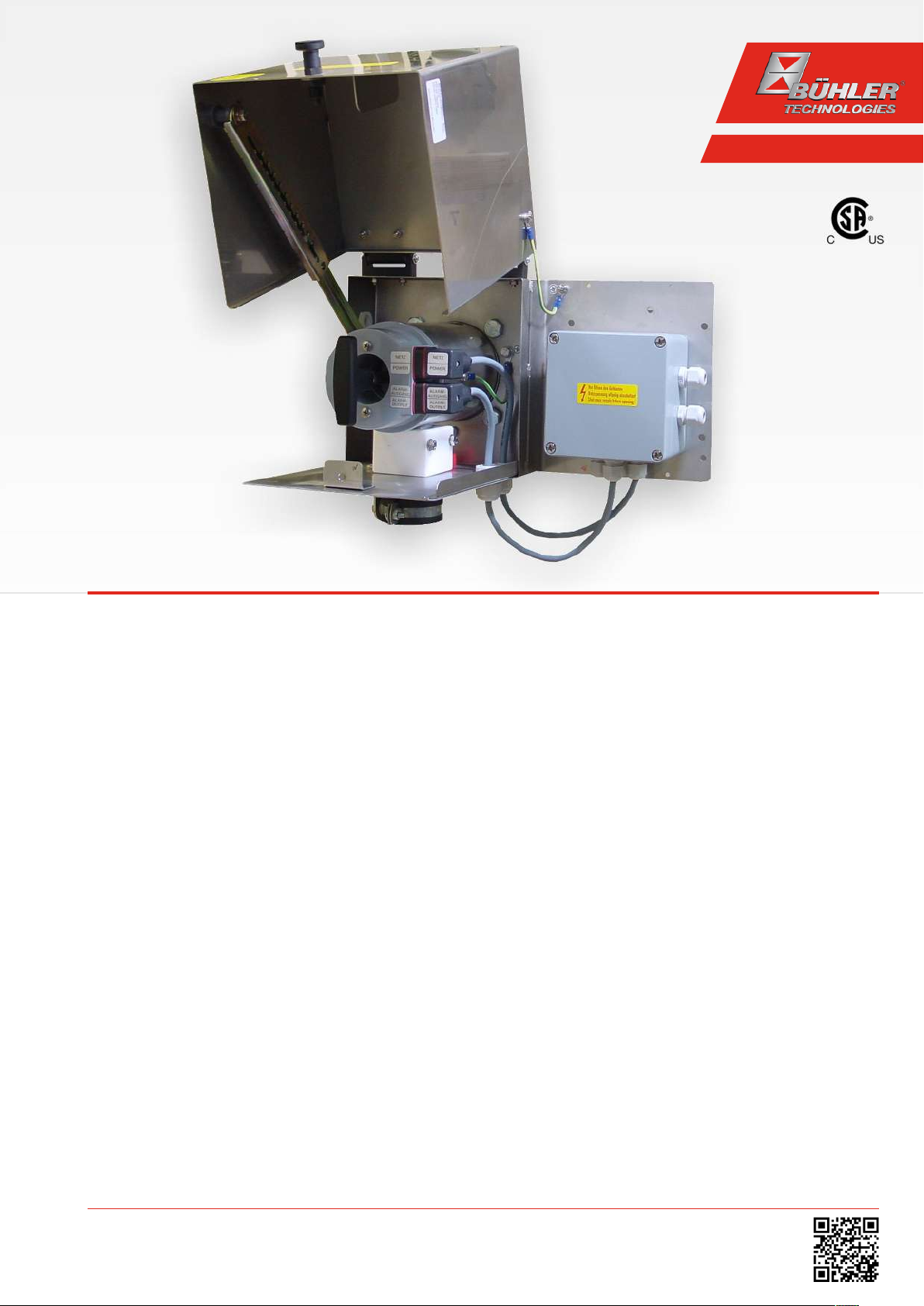
Sample gas probes
GAS 222.35 AMEX
Installation and Operation Instructions
Original instructions
BE460058
08/2019
Bühler Technologies GmbH, Harkortstr. 29, D-40880 Ratingen
Tel. +49 (0) 21 02 / 49 89-0, Fax: +49 (0) 21 02 / 49 89-20
E-Mail: analyse@buehler-technologies.com
Internet: www.buehler-technologies.com
Page 2

Bühler Technologies GmbH, Harkortstr. 29, D-40880 Ratingen
Tel. +49 (0) 21 02 / 49 89-0, Fax: +49 (0) 21 02 / 49 89-20
Internet: www.buehler-technologies.com
E-Mail: analyse@buehler-technologies.com
Read this instruction carefully prior to installation and/or use. Pay attention particularly to all advises and safety instructions to prevent injuries. Bühler Technologies can not be held responsible for misusing
the product or unreliable function due to unauthorised modifications.
All rights reserved. Bühler Technologies GmbH 2019
Document information
Document No......................................................... BE460058
Version.........................................................................08/2019
Page 3

GAS 222.35 AMEX
Table of Contents
1 Introduction..................................................................................................................................................................................................................... 2
1.1 Intended Use......................................................................................................................................................................................................... 2
1.2 Type Plate............................................................................................................................................................................................................... 2
1.3 Scope of Delivery.................................................................................................................................................................................................. 2
1.4 Ordering instructions ........................................................................................................................................................................................3
1.5 Product Description............................................................................................................................................................................................ 3
2 Safety instructions.........................................................................................................................................................................................................4
2.1 Important advice ................................................................................................................................................................................................. 4
2.2 General Hazard Warnings ................................................................................................................................................................................5
3 Transport and storage .................................................................................................................................................................................................. 7
4 Installation and connection........................................................................................................................................................................................8
4.1 Installation site requirements.........................................................................................................................................................................8
4.2 Installation ............................................................................................................................................................................................................8
4.3 Installing the Inlet Filter ....................................................................................................................................................................................8
4.4 Insulation...............................................................................................................................................................................................................8
4.5 Connecting the Gas Line....................................................................................................................................................................................9
4.5.1 Blowback Connection ......................................................................................................................................................................... 9
4.5.2 Connecting the Gas Line .................................................................................................................................................................... 9
4.5.3 Connecting the calibrating gas line (optional)..........................................................................................................................10
4.6 Connecting the Blowback and Pressure Vessel (Optional) ...................................................................................................................10
4.7 Electrical connections ......................................................................................................................................................................................10
4.7.1 Heated pressure vessel (optional) ..................................................................................................................................................11
5 Operation and Control.................................................................................................................................................................................................13
5.1 Before Start-Up ...................................................................................................................................................................................................13
6 Maintenance.................................................................................................................................................................................................................. 14
6.1 Maintaining the filter element ......................................................................................................................................................................15
6.1.1 Replacing the Inlet Filter .................................................................................................................................................................. 15
6.2 Blowback of the in-situ filter (within the process stream).................................................................................................................... 16
6.2.1 Manual Blowback (Without Blowback Control) ........................................................................................................................16
6.2.2 Automatic Blowback (External Blowback Control)...................................................................................................................16
6.3 Maintenance Schedule .....................................................................................................................................................................................17
7 Service and repair......................................................................................................................................................................................................... 18
7.1 Troubleshooting ................................................................................................................................................................................................ 18
7.2 Spare Parts and Accessories ...........................................................................................................................................................................19
8 Disposal...........................................................................................................................................................................................................................20
9 Appendices......................................................................................................................................................................................................................21
9.1 Technical Data .................................................................................................................................................................................................... 21
9.2 Connection Diagram ........................................................................................................................................................................................ 21
9.3 Connection diagram heated pressure vessel............................................................................................................................................22
9.4 Flow diagram......................................................................................................................................................................................................22
9.5 Dimensions ......................................................................................................................................................................................................... 23
9.6 List of chemical resistance..............................................................................................................................................................................24
9.7 User book (Please make copies) .................................................................................................................................................................... 25
10 Attached Documents...................................................................................................................................................................................................26
iBühler Technologies GmbHBE460058 ◦ 08/2019
Page 4
GAS 222.35 AMEX
GAS 222.35 AMEX
100105177 462223516633000999999 001
Cl. 1, Div. 2, Gps. B, C, D, T3
CSA Certificate: 1728394
Install per drawing 46/115-Z01-06-4
115-230 V; max. 360W @ 230V
at -20 up to 80 °C; max. 6 bar
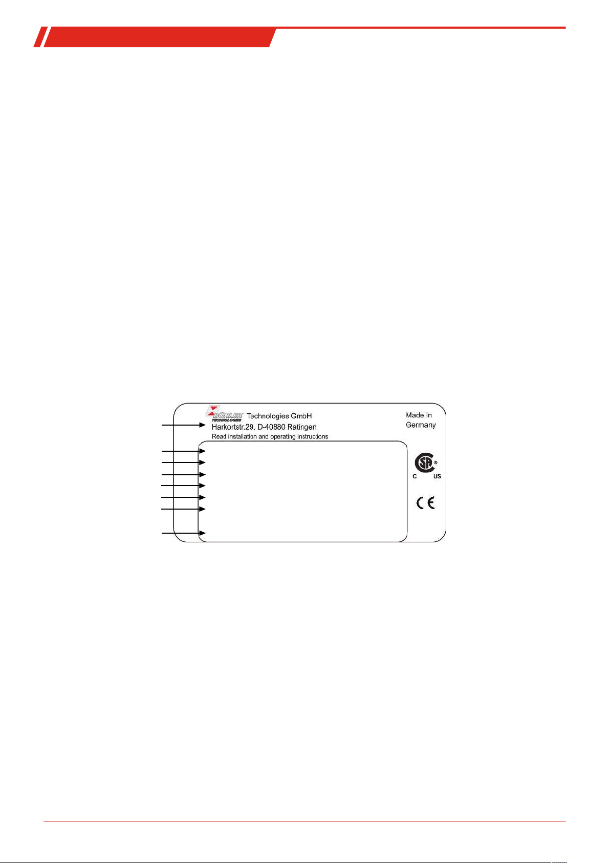
Manufacturer and address
Year: 2019
Type designation
Order no., Item no.
Blast protection marking
CSA certificate number
Drawing number
Item description
Year of manufacture
1 Introduction
1.1 Intended Use
The sample gas probe is intended for installation into gas analysis systems in commercial applications.
Sample gas probes are among the main components in a gas conditioning system.
– Therefore also note the related drawing in the data sheet in the appendix.
– Before installing the device, verify the listed technical data meet the application parameters.
– Further verify all contents are complete.
Please refer to the type plate to identify your model. In addition to the job number/ID number, this also contains the article
number and model designation.
Please note the specific values of the device when connecting, and the correct versions when ordering spare parts.
Passing through gases
Flammable gases above the UEL may only be blown back with inert gases. Flammable gases from 25% LEL and up to the UEG
may be blown back provided the operator ensures the blown back gas is not and cannot be explosive. For safety reasons we recommend only using inert gases in these cases as well.
Blowing back explosive atmospheres (range from UEG to OEG) with the probes is prohibited due to possible adiabatic compression (high blowback pressure against contaminated filter). The operator is responsible for compliance with these conditions taking into account his risk assessment.
1.2 Type Plate
Example:
1.3 Scope of Delivery
– 1 x Sample gas probe
– 1 x Flange gasket and screws
– Product documentation
– Connection and mounting accessories (only optional)
2 Bühler Technologies GmbH BE460058 ◦ 08/2019
Page 5

GAS 222.35 AMEX
1.4 Ordering instructions
The item number is a code for the configuration of your unit. Please use the following model key:
4622235 1 6 6 X 3 X 0 0 X 9 X 9 9 9 Product Characteristics
1)
Ex temperature classes
3 T3
4 T4
Sample probe power supply
3 115 / 230 V
Calibration gas connection
0 No calibration gas connection
1 6 mm
2 6 mm + check valve
3 1/4"
4 1/4" + check valve
Blowback with air reservoir
2)
Air reservoir heating
1 Yes
9 No
Compressed air valve/valve voltage information
0 Manual
1 120 V 60 Hz
2 240 V 60 Hz
9 None (if no blowback requested)
Pneumatic drive for ball valve
9 N/A
Control valve for pneumatic drive
9 No control valve
1)
Please note, using certain accessories may limit gas probe use in Ex areas! Observe the respective operating manuals, accessory
compatibility charts, and data sheets to ensure proper technical product design!
2)
In the case of flammable gases, always use inert gas for blowback. Probe blowback prohibited when using explosive sample
gas!
1.5 Product Description
The probe is equipped with self-regulating PTC heating cartridges and a temperature contact.
Probe Description
GAS 222.35 AMEX Probe with retractable inlet filter and blowback connection
Accessories Please refer to the data sheet at the end of this manual for accessories for this probe
3Bühler Technologies GmbHBE460058 ◦ 08/2019
Page 6
GAS 222.35 AMEX
DANGER
WARNING
CAUTION
NOTICE
2 Safety instructions
2.1 Important advice
This unit may only be used if:
– the product is being used under the conditions described in the operating- and installation instructions, used according to
the nameplate and for applications for which it is intended. any unauthorized modifications to the device will void the warranty provided by Bühler Technologies GmbH,
– the limits in the data sheet and the instructions must be observed,
– the temperature switch is being operated on an intrinsically-safe circuit,
– the controller itself is installed outside the explosive area,
– Monitoring equipment / protection devices must be connected correctly,
– service and repairs not described in these instructions is performed by Bühler Technologies GmbH,
– using genuine replacement parts.
– Regulation IEC/EN60079-14 must be observed when erecting electrical systems in explosive areas.
– Additional national regulations pertaining to initial operation, operation, maintenance, repairs and disposal must be ob-
served.
– These operating instructions are a part of the equipment. The manufacturer reserves the right to change performance-, spe-
cification- or technical data without prior notice. Please keep these instructions for future reference.
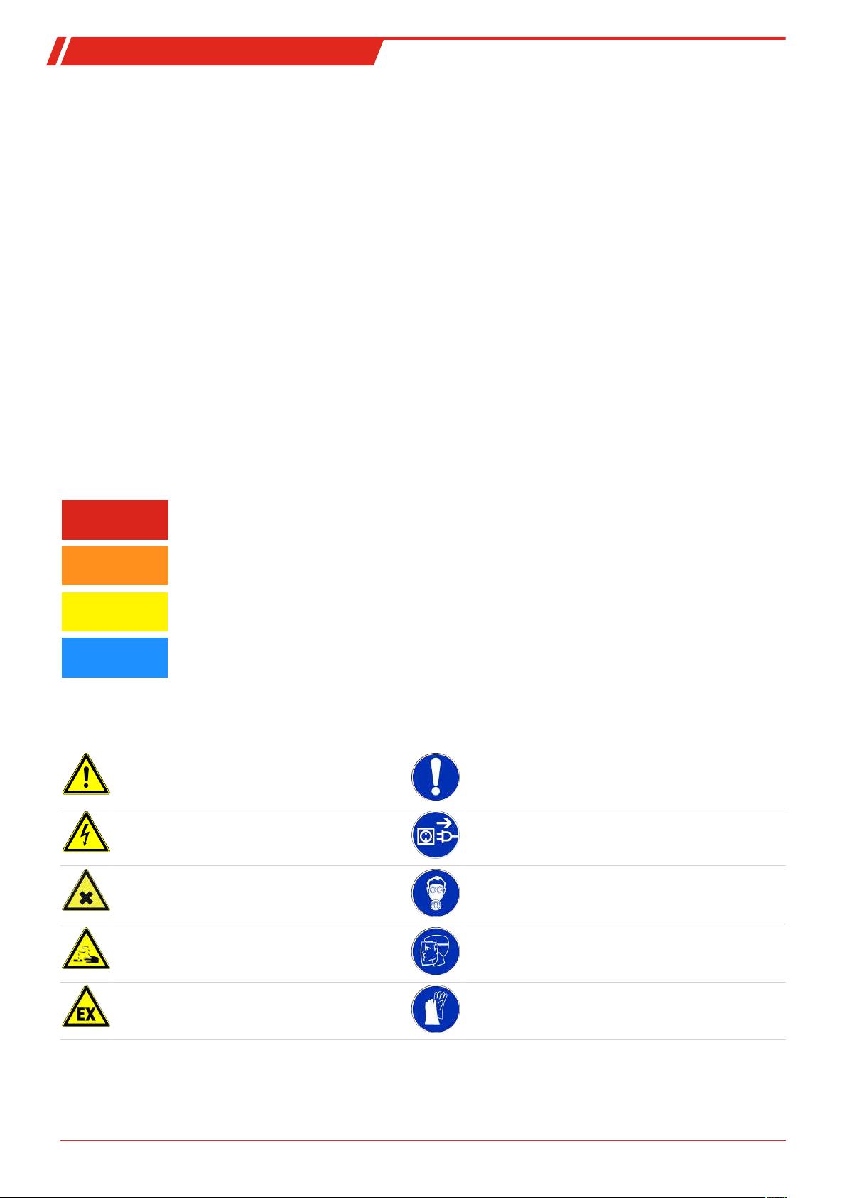
Signal words for warnings
Signal word for an imminent danger with high risk, resulting in severe injuries or death if not avoided.
Signal word for a hazardous situation with medium risk, possibly resulting in severe injuries or death if not
avoided.
Signal word for a hazardous situation with low risk, resulting in damaged to the device or the property or
minor or medium injuries if not avoided.
Signal word for important information to the product.
Warning signs
These instructions use the following warning signs:
Warns of a general hazard General notice
Warns of voltage Unplug from mains
Warns not to inhale toxic gasses Wear respiratory equipment
Warns of corrosive liquids Wear a safety mask
Warns of explosive areas Wear gloves
4 Bühler Technologies GmbH BE460058 ◦ 08/2019
Page 7
GAS 222.35 AMEX
2.2 General Hazard Warnings
The maximum surface temperature of the probes solely varies by operating conditions
temperature, ambient temperature, fluid flow rate). For use
ings.
The equipment must be installed by a professional familiar with the safety requirements and risks.
Be sure to observe the safety regulations and generally applicable rules of technology relevant for the installation site. Prevent
malfunctions and avoid personal injuries and property damage.
in explosive areas
please particularly note the related hazard warn-
(steam temperature, sample gas inlet
The operator of the system must ensure:
– Safety notices and operating instructions are available and observed,
– The respective national accident prevention regulations are observed,
– The permissible data and operational conditions are maintained,
– Safety guards are used and mandatory maintenance is performed,
– Legal regulations are observed during disposal,
– compliance with national installation regulations.
Maintenance, Repair
Please note during maintenance and repairs:
– Repairs to the unit must be performed by Bühler authorised personnel.
– Only perform conversion-, maintenance or installation work described in these operating and installation instructions.
– Always use genuine spare parts.
Always observe the applicable safety and operating regulations in the respective country of use when performing any type of
maintenance.
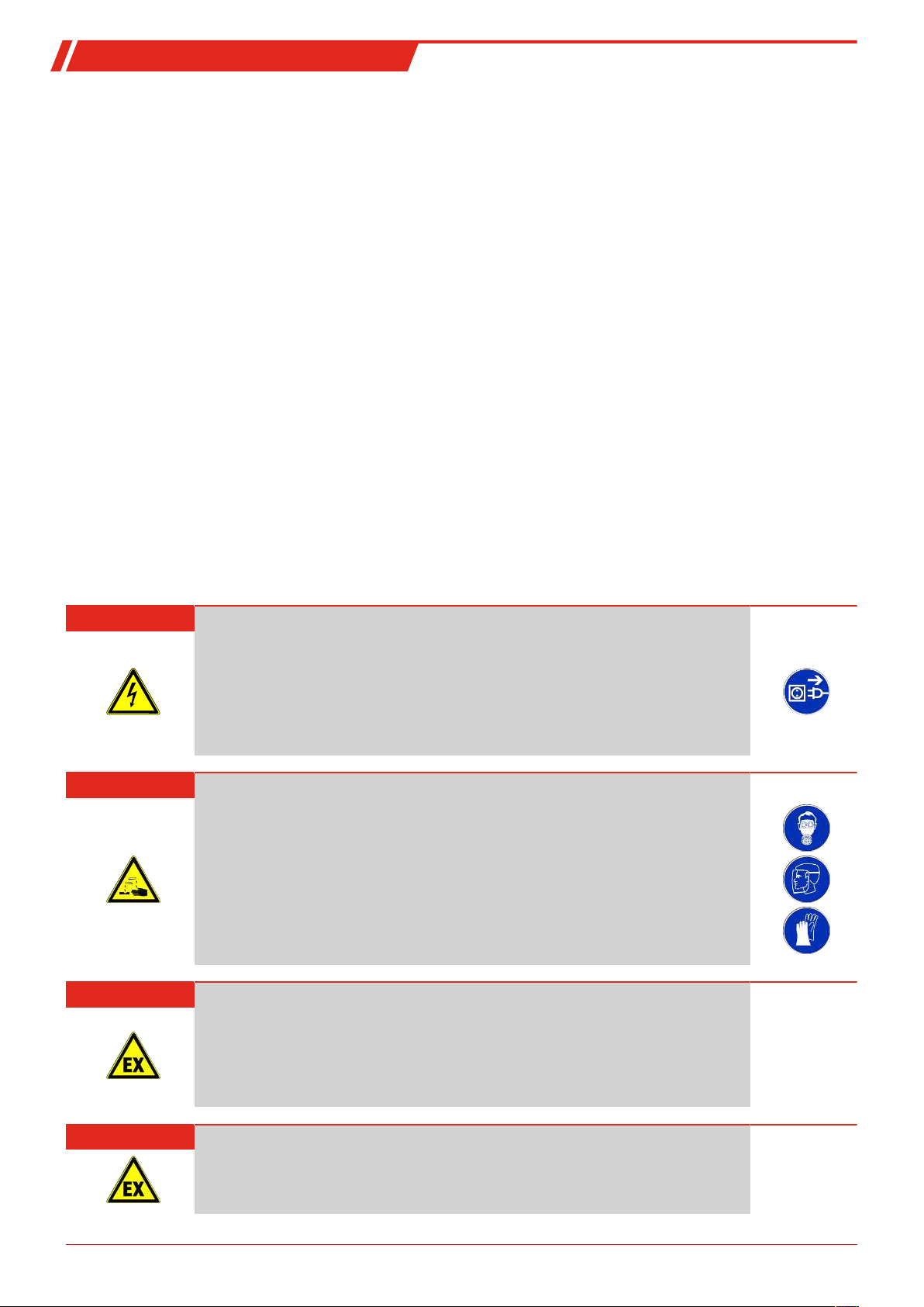
DANGER Electrical voltage
Electrocution hazard.
a) Disconnect the device from power supply.
b) Make sure that the equipment cannot be reconnected to mains unintentionally.
c) The device must be opened by trained staff only.
d) Regard correct mains voltage.
DANGER Toxic, corrosive gas/condensate
Sample gas/condensate may be hazardous to health.
a) If necessary, ensure a safe gas/condensate discharge.
b) Always disconnect the gas supply when performing maintenance or repairs.
c) Protect yourself from toxic/corrosive gasses/condensate when performing mainten-
ance. Wear appropriate protective equipment.
DANGER Explosion hazard
Life and explosion risk may result from gas leakage due to improper use.
a) Use the devices only as described in this manual.
b) Regard the process conditions.
c) Check tubes and hoses for leakage.
DANGER Danger to life and explosion during installation and maintenance
The unit must not be worked on (assembly, installation, maintenance) in explosive atmospheres.
5Bühler Technologies GmbHBE460058 ◦ 08/2019
Page 8

GAS 222.35 AMEX
DANGER
Use in explosive areas
Flammable gasses and dust could ignite or explode. Avoid the following hazard sources:
Application area!
Never operate the gas probe outside the specifications. Extracting gases or gas mixtures
which are also explosive in the absence of air is prohibited.
Electrostatic charge (sparking)!
The equipment may only be used where normal operating conditions do not frequently
produce flammable, electrostatic discharge.
Always clean plastic housing parts and decals with a damp cloth.
Sparking!
Protect the equipment from external blows.
Flame propagation!
If the process holds a risk of flame propagation, install a flame arrestor.
Adiabatic compression (explosion hazard)
Adiabatic compression may cause high gas temperatures during blowback.
back if gases are explosive. Only use nitrogen (inert gas) to blowback
Dust:
If possible, take the electrical components which must be opened for repair to a dustfree room. If unable to do so, prevent dust from entering the housing.
Ignition of dust layers!
When using the device in a dusty environment, routinely clean dust from all components.
The ignition temperature resp. smouldering temperature of flammable dusts resp. dust
layers present must be considerably higher than the maximum surface temperature of
the probe (observe applicable standards and statutory regulations).
Never blow-
flammable
gas
.
6 Bühler Technologies GmbH BE460058 ◦ 08/2019
Page 9

GAS 222.35 AMEX
3 Transport and storage
Only transport the product inside the original packaging or a suitable alternative.
The equipment must be protected from moisture and heat when not in use. They must be stored in a covered, dry and dust-free
room at a temperature between -20°C to 50°C (-4°F to 122°F).
7Bühler Technologies GmbHBE460058 ◦ 08/2019
Page 10
GAS 222.35 AMEX
4 Installation and connection
4.1 Installation site requirements
Sample gas probes are intended for flange mounting.
– Installation site and installation position are determined based on requirements specific to the application.
– If necessary, the connection piece should be slightly tilted toward the centre of the channel.
– The installation site should be protected from the weather.
– In addition, adequate and safe access for installation and future maintenance work should be provided. Particularly follow
the uninstalled size of the probe tube!
If the probe is transported to the installation site in pieces, it will first need to be assembled.
4.2 Installation
DANGER Danger to life and explosion during installation and maintenance
The unit must not be worked on (assembly, installation, maintenance) in explosive atmospheres.
DANGER Explosion hazard
When used in explosive areas
Flammable gasses and dust could ignite or explode.
Never operate the gas probe outside the specifications. Extracting gases or gas mixtures
which are also explosive in the absence of air is prohibited.
DANGER Explosion hazard due to ignition of dust
When using the device in a dusty environment, routinely clean dust from all components.
The ignition temperature resp. smouldering temperature of flammable dusts resp. dust
layers present must be considerably higher than the maximum surface temperature of
the device (observe applicable standards and statutory regulations).
If possible, take the electrical components which must be opened for repair to a dustfree room. If unable to do so, prevent dust from entering the housing.
DANGER Explosion hazard due to flame propagation
Severe injuries and damage to the system
If the process holds a risk of flame propagation, install a flame arrestor.
4.3 Installing the Inlet Filter
The inlet filter, if necessary with matching extension, must be screwed in. The probe is then attached to the mating flange using
the included seals and screws.
4.4 Insulation
On heated probes completely insulate any exposed flange areas and, if applicable, the connection piece to absolutely prevent
thermal bridges. The insulating material must meet the application requirements and be weatherproof.
8 Bühler Technologies GmbH BE460058 ◦ 08/2019
Page 11
GAS 222.35 AMEX
4.5 Connecting the Gas Line
The sample gas line must be carefully and properly connected using a suitable fitting.
This table provides an overview of the sample gas probe connections:
Probe
GAS 222
Reservoir
PAV01
Ball valve
pneumatic drive
Control valve
3/2-way solenoid
valve
Connecting flange
1)
DN65/PN6/
DN3“-150
2)
Sample gas inlet G3/4
Sample gas outlet NPT 1/4
Blowback connection G3/8
Test gas connection
1)
Tube Ø6 mm
Tube Ø1/4
2)
Filling port NPT 1/4
Condensate G1/2
Bypass NPT 1/4
Control air G1/8 G1/4
NPT 1/4
Tab.1: Gas Probe Connections (Varies by Model)
1)
Varies by version.
2)
Only GAS 222.xx ANSI and GAS 222.xx AMEX
WARNING Gas emanation
Sample gas can be harmful to the health!
Check the lines for leaks.
4.5.1 Blowback Connection
If the probe has a G3/8 blowback connection, without factory installed blowback device it will be open. The blowback connection
must be sealed gas-tight prior to start-up.
DANGER Toxic, corrosive gasses
Explosive or toxic gases can develop due to a leaking or open blowback connection.
4.5.2 Connecting the Gas Line
Please note the following items when connecting the sample gas line (NPT 1/4") on heated probes to prevent thermal bridges:
– Choose the shortest possible screw connection.
– Shorten the connection pipe for the sample gas line as much as possible. To do so, remove the insulation around the sample
gas line. This is done by loosening the fixing bolts.
CAUTION Fragile
The insulation is fragile. Handle with care, do not drop.
After connecting the sample gas line it must be braced and secured with the clamp.
Long sample gas lines may require additional support clamps along the way to the analysis system! Once all lines have been
connected and checked for leaks, carefully reinstall and secure the insulation.
9Bühler Technologies GmbHBE460058 ◦ 08/2019
Page 12
GAS 222.35 AMEX
WARNING Gas emanation
Sample gas can be harmful to the health!
Check the lines for leaks.
4.5.3 Connecting the calibrating gas line (optional)
Connecting the calibrating gas line requires a Ø6 mm or Ø1/4” pipe fitting.
If the calibrating gas connection was ordered with check valve, a Ø6 mm or Ø1/4” pipe can be connected directly to the check
valve.
4.6 Connecting the Blowback and Pressure Vessel (Optional)
The air lines must be connected carefully and properly, using suitable fittings.
If the probe is equipped with pressure vessel for efficient blowback (optional), a manual shut-off valve (ball valve) must be installed in the air supply, immediately upstream from the pressure vessel.
On probes used to sample flammable gas, nitrogen (inert gas) must be used for blowback. Blowback of explosive gases is prohibited.
NOTICE
The operating pressure of the compressed air (inert gas) required for blowback must always be higher than the process pressure.
Required pressure differential min. 3 bar (44 psi).
DANGER Broken pressure vessel
Gas leak, danger due to flying parts.
Maximum operating pressure of the pressure vessel 10 bar (145 psi)!
The operating pressure reduces based on the operating voltage (see solenoid valve type
plate).
DANGER Adiabatic compression during gas blowback (explosion hazard)!
Adiabatic compression may cause high gas temperatures and must be checked by the
user.
Gas blowback may result in high gas temperatures due to adiabatic compression. This
can cause flammable gases to ignite spontaneously.
a) Blowback of explosive atmosphere / gases is prohibited.
b) Flammable atmosphere / gases (non-explosive) may only be blown back with nitro-
gen (inert gas).
4.7 Electrical connections
WARNING Hazardous electrical voltage
The device must be installed by trained staff only.
CAUTION Wrong mains voltage
Wrong mains voltage may damage the device.
Regard the correct mains voltage as given on the type plate.
10 Bühler Technologies GmbH BE460058 ◦ 08/2019
Page 13
GAS 222.35 AMEX
CAUTION Equipment damage
Cables damaged
Do not damage the cable during installation. Install a strain relief for the cable connection. Secure the cable against twisting and loosening. Please note the temperature resistance of the cables (> 100°C/212°F).
The probe includes two cubic plugs per EN 175301-803 (ex DIN43650) and a junction box. The plugs are prewired to the junction
box. For safety reasons this connection must not be modified. The electrical connections must only be run to the terminals of the
junction box.
The power supply for the two heating cartridges (mains supply 115/230V, 50/60 Hz) and the connection for the thermal alarm
contact are provided via the terminal strip in the junction box. Per EN 60079-14 and -15, connection for the alarm output must
be connected energy-limited (U
– Only use cables with a temperature resistance of >100°C to connect to power.
– Make sure the connecting cable has sufficient strain relief (match cable diameter to the seal on the cubic plug).
– Please note, the heating system briefly has high starting currents (max. 6A). Use a suitable fuse (8A). When connecting,
please also observe the applicable Ex protection regulations.
NOTICE
The thermal alarm contact must be connected energy-limited!
(U
= 30 V, I
max
= 30 V, I
max
max
= 100 mA). Please see the enclosed terminal diagram for the connection.
max
= 100 mA)
WARNING High voltage
Damage to the device in case of insulation testing
Do not proceed insulation tests with high voltage
to the device as a whole!
Electric strength test
The necessary tests of all assemblies required to be tested were carried out at the factory (test voltage 1 kV or 1.5 kV depending
on component).
To check the electric strength again yourself, only do so on the respective individual components.
– Now perform the electric strength test against earth.
4.7.1 Heated pressure vessel (optional)
A heated blowback vessel may optionally be used for blowback. Heated via self-regulating PTC heating cartridge to protect
against frost.
The electrical (mains connection 115/230 V AC) connects via the junction box per the enclosed terminal diagram at the end.
– Only use cables with a temperature resistance of >100°C to connect to power.
– Make sure the connecting cable has sufficient strain relief (match cable diameter to the seal on the junction box).
– When connecting, also observe the applicable Ex protection regulations and general warnings in these operating instruc-
tions.
CAUTION Equipment damage
Cables damaged
Do not damage the cable during installation. Install a strain relief for the cable connection. Secure the cable against twisting and loosening. Please note the temperature resistance of the cables (> 100°C/212°F).
11Bühler Technologies GmbHBE460058 ◦ 08/2019
Page 14

GAS 222.35 AMEX
DANGER Adiabatic compression during gas blowback (explosion hazard)!
Adiabatic compression may cause high gas temperatures and must be checked by the
user.
Gas blowback may result in high gas temperatures due to adiabatic compression. This
can cause flammable gases to ignite spontaneously.
a) Blowback of explosive atmosphere / gases is prohibited.
b) Flammable atmosphere / gases (non-explosive) may only be blown back with nitro-
gen (inert gas).
12 Bühler Technologies GmbH BE460058 ◦ 08/2019
Page 15

GAS 222.35 AMEX
5 Operation and Control
NOTICE
The device must not be operated beyond its specifications.
NOTICE
The weather hood must be closed during operation!
WARNING Housing or component damage
Never exceed the maximum working pressure and temperature range of the drive.
DANGER Explosion hazard due to electrostatic discharge
Equipment may only be used where normal operating conditions do not produce frequent flammable, electrostatic discharge.
5.1 Before Start-Up
Before starting the device, verify:
– The hose and electrical connections and the heating tape are not damaged and installed correctly.
– No parts of the sample gas probe have been removed.
– The protection and monitoring devices are installed and functional (e.g. flame arrester).
– The gas inlet and outlet on the gas probe are open.
– Ambient parameters are met.
– Probe parts are resistant to media to be conveyed and in the surrounding area.
– The performance specifications in the type plate are met.
– The voltage and frequency of the heating tape match the mains values.
– The temperature has an energy-limited connection (U
– The electrical connections are tight.
– The monitoring equipment is connected and set as specified.
– All connection cables are installed without strain.
– Precautions have been taken; earthing.
– The junction box cover is closed and the cable gland is properly sealed.
= 30V, I
max
= 100 mA).
max
13Bühler Technologies GmbHBE460058 ◦ 08/2019
Page 16

GAS 222.35 AMEX
6 Maintenance
– Damaged parts must be replaced immediately.
– Regularly check the function of the electrical protection.
During maintenance, remember:
– The equipment must be maintained by a professional familiar with the safety requirements and risks.
– Only perform maintenance work described in these operating and installation instructions.
– When performing maintenance of any type, observe the respective safety and operation regulations.
DANGER Danger to life and explosion during installation and maintenance
The unit must not be worked on (assembly, installation, maintenance) in explosive atmospheres.
DANGER Electrical voltage
Electrocution hazard.
a) Disconnect the device from power supply.
b) Make sure that the equipment cannot be reconnected to mains unintentionally.
c) The device must be opened by trained staff only.
d) Regard correct mains voltage.
DANGER Toxic, corrosive gases
The measuring gas led through the equipment can be hazardous when breathing or
touching it.
a) Check tightness of the measuring system before putting it into operation.
b) Take care that harmful gases are exhausted to a save place.
c) Before maintenance turn off the gas supply and make sure that it cannot be turned
on unintentionally.
d) Protect yourself during maintenance against toxic / corrosive gases. Use suitable pro-
tective equipment.
CAUTION Hot surface
Risk of burns
Depending on the operating parameters, the housing temperature may reach over 100
°C during operation.
Allow the unit to cool down before performing maintenance.
CAUTION Excess pressure
The unit mustn’t be pressurised or energised when opened.
If necessary, close the gas supply and ensure a safe pressure on the process end before
opening.
DANGER Dangerous electrostatic charge (explosion hazard)
Incendive electrostatic charges may occur when cleaning plastic housing parts and
decals (e.g. with a dry cloth or compressed air). The sparks this produces could ignite
flammable, explosive atmospheres.
Always clean plastic housing parts and decals
14 Bühler Technologies GmbH BE460058 ◦ 08/2019
with a damp cloth
!
Page 17

GAS 222.35 AMEX
DANGER Explosion hazard due to ignition of dust
When using the device in a dusty environment, routinely clean dust from all components.
The ignition temperature resp. smouldering temperature of flammable dusts resp. dust
layers present must be considerably higher than the maximum surface temperature of
the device (observe applicable standards and statutory regulations).
If possible, take the electrical components which must be opened for repair to a dustfree room. If unable to do so, prevent dust from entering the housing.
6.1 Maintaining the filter element
The probes feature a particle filter which needs to be changed as it becomes dirty.
To do so, disconnect the voltage supply and if applicable close the shut-off valve to the process or switch off the process.
CAUTION!Do not damage the rear filter seat.
NOTICE
Ceramic filter elements
fall.
Filter elements made out of sintered stainless steel
and be used several times as long as both seals are still in proper conditions.
are very brittle by nature. Handle them with care, don’t let them
can be cleaned in an ultrasonic bath
6.1.1 Replacing the Inlet Filter
The probes are equipped with an inlet filter which is always inside the process stream. The filter is suitable for blowback with
compressed air (inert gas), i.e. blowing air (inert gas) through the filter from the inside to the outside to remove adhering
particles. When sampling flammable gases, nitrogen (inert gas) must be used for blowback. Blowback of explosive gases is prohibited.
The effectiveness of cleaning a filter within a process is directly influenced by the available airflow (amount of gas). We therefore recommend using a pressure vessel directly on the probe.
With sufficient inlet filter blowback (within the process stream) the probes are maintenance-free. However, due to process conditions the filter may clog over time. In this case the filter element will need to be replaced.
Proceed as follows:
– Slightly push in the handle at the back of the probe and turn 90° (handle must then be horizontal) and remove.
– Screw the dirty filter element out of the handle.
– Check the sealing faces on the handle, replace O-rings, then install the filter element and new seal. (The spare filter includes
O-rings and seals).
– Then insert the handle with the new or cleaned filter, push in slightly and turn 90° (handle must then be vertical). Pull on the
handle to verify the filter element is firmly seated.
NOTICE
The weather hood can only be closed again when the handle is completely vertical. In order to do so, loosen the hood from the locking supports by lifting slightly and then fold
down. Ensure that the hood lock clicks into place correctly.
Condensate inside the pressure vessel
Depending on the installation site and application conditions a small amount of condensate may form inside the blowback air
pressure vessel. Open the drain screw at the bottom of the vessel and drain the condensate at least once a year.
If the probe needs to be serviced more frequently due to operating conditions, we recommend also draining the condensate at
these intervals.
CAUTION High pressure
Pressure vessel under pressure.
Before opening the condensate drain, close the air supply to the blowback control and
drain the vessel by manual blowback.
Pressing the main switch for the blowback control to interrupt the voltage supply.
15Bühler Technologies GmbHBE460058 ◦ 08/2019
Page 18

GAS 222.35 AMEX
6.2 Blowback of the in-situ filter (within the process stream)
DANGER Adiabatic compression during gas blowback (explosion hazard)!
Adiabatic compression may cause high gas temperatures and must be checked by the
user.
Gas blowback may result in high gas temperatures due to adiabatic compression. This
can cause flammable gases to ignite spontaneously.
a) Blowback of explosive atmosphere / gases is prohibited.
b) Flammable atmosphere / gases (non-explosive) may only be blown back with nitro-
gen (inert gas).
Be sure to use filtered air with a minimum rating of PNEUROP / ISO Class 4 for blowback:
Class Particles / m
Particle size:
(1 to 5) µm
4
to 1000
(no particles ≥ 15 µm)
3
Pressure dew point
[°C]
≤ 3 ≤ 5
Residual oil content
[mg / m3]
6.2.1 Manual Blowback (Without Blowback Control)
The shut-off valve in the air supply (inert gas supply) to the pressure vessel must be open. The optional pressure gauge on the
pressure vessel shows the current operating pressure.
Abruptly
–
gauge has dropped to the lowest reading.
open the ball valve in the connecting line from the pressure vessel to the probe until the display on the pressure
6.2.2 Automatic Blowback (External Blowback Control)
Automatic blowback requires a shut-off valve downstream from the probe. The control unit for the system is designed for sequential valve control, i.e.:
1. Closing the shut-off valve downstream from the probe with a controller.
2. Open the solenoid valve between the pressure vessel and probe for approx. 10 seconds.
3. Open the shut-off valve downstream from the probe again.
Blowback can also be set as a closed process at intervals ranging from several minutes to hours or even days based on requirements.
16 Bühler Technologies GmbH BE460058 ◦ 08/2019
Page 19

GAS 222.35 AMEX
6.3 Maintenance Schedule
NOTICE
When using the probe in explosive areas the maintenance schedule must be observed!
Maintenance schedule for normal ambient conditions:
Component Interval in operating
hours
Entire probe every 8000 h – Check gas connections
– Check safety devices and controllers
– Check electrical protective measures
– Proper function, dirt, visual inspection for dirt / dam-
age.
If damaged, replace or have repaired by Bühler.
Ball valves every 8000 h – Check ball valve function and check for leaks. Operator
Filter every 8,000 h – Check dirt level of filter. Operator
Seals every 8,000 h – Replace O-rings.
– Replace seals after every filter change.
Pressure vessel every 8,000 h – Drain condensate Operator
Entire probe
With respect to the
ball valve and solenoid
valves
after 20,000 h or
3years
– Inspection by Bühler Service technician /
Work to be performed To be performed by
Operator
Operator
Bühler
17Bühler Technologies GmbHBE460058 ◦ 08/2019
Page 20

GAS 222.35 AMEX
7 Service and repair
This chapter contains information on troubleshooting and correction should an error occur during operation.
Repairs to the unit must be performed by Bühler authorised personnel.
Please contact our Service Department with any questions:
Tel.: +49-(0)2102-498955
If the equipment is not functioning properly after correcting any malfunctions and switching on the power, it must be inspected
by the manufacturer. Please send the equipment inside suitable packaging to:
Bühler Technologies GmbH
- Reparatur/Service -
Harkortstraße 29
40880 Ratingen
Germany
Please also attach the completed and signed RMA decontamination statement to the packaging. We will otherwise be unable to
process your repair order.
You will find the form in the appendix of these instructions, or simply request it by e-mail:
service@buehler-technologies.com
or your agent
.
7.1 Troubleshooting
CAUTION Risk due to defective device
Personal injury or damage to property
a) Switch off the device and disconnect it from the mains.
b) Repair the fault immediately. The device should not be turned on again before elim-
ination of the failure.
Problem / malfunction Possible cause Action
No or reduced gas flow – Filter element clogged – Clean or replace filter element
– Gas circuit clogged – Clean sampling tube
– Ball valve closed – Open ball valve
– Blowback (optional) not responding – Check compressed air supply
– Check solenoid valve, check pneumatic con-
trol
No heat output – No/incorrect power supply – Check power supply
Condensation forming – Heater defective – Send in probe for repair
– Thermal bridges at the sampling point – Insulate to eliminate thermal bridges
18 Bühler Technologies GmbH BE460058 ◦ 08/2019
Page 21

GAS 222.35 AMEX
7.2 Spare Parts and Accessories
Please also specify the model and serial number when ordering parts.
Upgrade and expansion parts can be found in our catalog.
Available spare parts:
Item no. Description
90 091 05 Measuring outlet seal
90 090 79 Flange seal DN65 PN6
46 222 351 5 O-ring kit for filter element and probe, material: Viton/Cu *
Please see the accessories data sheet in the appendix for filter elements
*Lowest ambient temperature: -20 °C (-4 °F)
The temperature limits of the seals in the low temperature range are particularly important and must be observed for unheated
probes. On heated probes the seals will have higher temperatures during normal operation, so the limits specified for the low
temperatures typically do not apply. When changing the seals in low temperatures the temperature limits must particularly be
observed, as the filter element and handle may have these low temperatures outside the probe.
19Bühler Technologies GmbHBE460058 ◦ 08/2019
Page 22

GAS 222.35 AMEX
8 Disposal
Dispose of parts so as not to endanger the health or environment. Follow the laws in the country of use for disposing of electronic components and devices during disposal.
20 Bühler Technologies GmbH BE460058 ◦ 08/2019
Page 23

GAS 222.35 AMEX
M16 x 1.5 mm
4.5 - 10 mm
Customer power supply
Customer alarm output
Probe
power
supply
Heater
power
supply
PAV 01
Alarm
output
M16 x 1.5 mm
4.5 - 10 mm
M16 x 1.5
M16 x 1.5
9 Appendices
9.1 Technical Data
Gas Probe Technical Data
Self-regulating temperature: 125 °C (T3)/70 °C (T4)
Ambient temperature: -20 to +80 °C
Ambient temperature with accessories:
Low temperature alarm: Contact open at operating temperature, closes at < 95 °C (T3) resp. < 50 °C (T4);
Electrical data: 115 V-230 V, 50/60 Hz
Max. operating pressure: 6 bar
Parts in contact with media: 1.4571
Explosion protection: Class 1, Div 2, Gps B, C, D
9.2 Connection Diagram
Component Ambient temperature range
Compressed air valve: -10 °C < T
U
=30 VDC, I
max
Seals: PTFE/Graphit/1.4404 and see filters
=100 mA, Ci/Li~0
max
< +55 °C
amb
21Bühler Technologies GmbHBE460058 ◦ 08/2019
Page 24

GAS 222.35 AMEX
Heater
Operating voltage
115-230 V AC 200 W
9.3 Connection diagram heated pressure vessel
9.4 Flow diagram
22 Bühler Technologies GmbH BE460058 ◦ 08/2019
Page 25

GAS 222.35 AMEX
9.5 Dimensions
23Bühler Technologies GmbHBE460058 ◦ 08/2019
Page 26

GAS 222.35 AMEX
9.6 List of chemical resistance
Materials of your device in contact with media are printed on the type plate.
Formula Medium Concentration Teflon®
PTFE
CH3COCH
C6H
6
CI
2
CI
2
C2H
6
3
Acetone 1/1 1/1 4/4 1/1
Benzol 1/1 1/1 3/3 1/1
Chlorine 10 % wet 1/1 1/1 3/0 4/4
Chlorine 97 % 1/0 1/0 1/1 1/1
Ethane 1/0 1/0 1/0 2/0
FFKM Viton®
FPM
V4A
C2H5OH Ethanol 50 % 1/1 1/1 2/2 1/0
C2H
4
C2H
2
C6H5C2H
5
Ethylene 1/0 1/0 1/0 1/0
Ethyne 1/0 1/0 2/0 1/0
Ethylbenzene 1/0 1/0 2/0 1/0
HF Hydrofluoric acid 1/0 2/0 4/0 3/4
CO
2
Carbon dioxide 1/1 1/0 1/1 1/1
CO Carbon monoxide 1/0 1/0 1/0 1/1
CH
4
Methane technically pure 1/1 1/0 1/1 1/1
CH3OH Methanol 1/1 1/1 3/4 1/1
CH3CI
H3PO
H3PO
C3H
2
4
4
8
Methylene chloride 1/0 1/0 3/0 1/1
Phosphoric acid 1-5 % 1/1 1/1 1/1 1/1
Phosphoric acid 30 % 1/1 1/1 1/1 1/1
Propane gaseous 1/1 1/0 1/0 1/0
C3H6O Propylene oxide 1/0 2/0 4/0 1/0
HNO
HNO
3
3
Nitric acid 1-10 % 1/1 1/0 1/1 1/1
Nitric acid 50 % 1/1 1/0 1/0 1/2
HCI Hydrochloric acid 1-5 % 1/1 1/1 1/1 2/4
HCI Hydrochloric acid 35 % 1/1 1/1 1/2 2/4
O
2
SF
6
H2SO
4
Oxygen 1/1 1/1 1/2 1/1
Sulphur hexafluoride 1/0 1/0 2/0 0/0
Sulfuric acid 1-6 % 1/1 1/1 1/1 1/2
H2S Hydrogen sulphide 1/1 1/1 4/4 1/1
N
2
C6H5C2H
C6H5CH
3
3
Nitrogen 1/1 1/0 1/1 1/0
Styrene 1/1 1/0 3/0 1/0
Toluol (methylbenzene) 1/1 1/1 3/3 1/1
H2O Water 1/1 1/1 1/1 1/1
H
2
Hydrogen 1/0 1/0 1/0 1/0
0 - no information available
1 - durability/suitability very good
2 - durability/suitability good
3 - limited suitability
4 - not suitable
Two values are specified per medium. Left number = value at 20 °C, right number = value at 50 °C.
Important information
The tables were listed based on specifications from various raw material manufacturers. The values solely refer to laboratory
tests using raw materials. Components made from these are often subject to impacts which cannot be determined in laboratory
testing (temperature, pressure, material strain, impacts of chemical agents, design features, etc.). The values specified can
therefore only serve as a guideline. When in doubt, we recommend performing a test. These specifications do not infer a legal
claim, we exclude any warranty and liability. The chemical and mechanical durability alone do not suffice to determine the usage property of a product, particularly e.g. the regulations for liquid fuels (Ex-protection) must be observed.
Durability to other mediums available upon request.
24 Bühler Technologies GmbH BE460058 ◦ 08/2019
Page 27

GAS 222.35 AMEX
9.7 User book (Please make copies)
Maintained on Unit no. Operating hours Remarks Signature
25Bühler Technologies GmbHBE460058 ◦ 08/2019
Page 28

GAS 222.35 AMEX
10 Attached Documents
– Certificate of Compliance: CSA 1728394
– Accessories Data Sheet 461099
– RMA - Decontamination Statement
26 Bühler Technologies GmbH BE460058 ◦ 08/2019
Page 29

Certificate of Compliance
Certificate:
Project:
Issued to: Bühler Technologies GmbH
1728394
2361506
Harkortstr. 29
Ratingen, D-40880
Germany
Attention: Christopher Sungergeld
The products listed below are eligible to bear the CSA
Mark shown with adjacent indicators 'C' and 'US' for
Canada and US or with adjacent indicator 'US' for
US only or without either indicator for Canada only.
PRODUCTS
CLASS 2252 81
CLASS 2252 01
- PROCESS CONTROL EQUIPMENT - Certified to US Standards
- PROCESS CONTROL EQUIPMENT
Issued by:
Master Contract:
Date Issued:
Joe da Silva
Joe da Silva, C.E.T.
231516
November 18, 2010
- Series GAS222.XX sample gas probes, Models GAS222.11ANSI/CSA, GAS222.30ANSI/CSA,
GAS222.35UANSI/CSA, GAS222.15ANSI/CSA, GAS222.17ANSI/CSA, GAS222.20ANSI/CSA,
GAS222.21ANSI/CSA, GAS222.31ANSI/CSA and GAS222.35ANSI/CSA, rated 115/230Vac, 50/60Hz, 440W,
max. Ambient 70°C max.
- Series AHF 22 heated sample gas filters, models AHF- 22-S-K and AHF-22-yyy-R-K, where yyy means the
mains voltage, 115 or 230V.
CLASS 2258 02 - PROCESS CONTROL EQUIPMENT - For Hazardous Locations
CLASS 2258 82 - PROCESS CONTROL EQUIPMENT - For Hazardous Locations - CERTIFIED TO U.S.
STANDARDS
Class I, Div 2, Groups B, C and D:
- Series GAS222.XX sample gas probes, Models GAS222.20 AMEX, GAS222.21 AMEX, GAS222.31AMEX,
GAS222.35 AMEX, GAS222.11ANSI/CSA, GAS222.30ANSI/CSA, GAS222.35UANSI/CSA, rated
115V/230V, 50/60Hz, 360W max, Ambient 80°C max., Temp code T3 or T4.
DQD 507 Rev. 2009-09-01 Page: 1
Page 30

Certificate:
1728394
Master Contract:
231516
Project:
2361506
Date Issued:
November 18, 2010
APPLICABLE REQUIREMENTS
CAN/CSA C22.2 No. 0-M91 (R2001) - General Requirements - Canadian Electrical Code, Part II
CSA Std C22.2 No. 142-M1987 - Process Control Equipment
CSA Std C22.2 No. 213-M1987 - Non-Incendive Electrical Equipment for Use in Class I, Division 2
Hazardous Locations
UL Std No. 1604, Third Ed.1994 - Electrical Equipment for Use in Class I and II, Division 2; Class III
Hazardous (Classified) Locations
UL Std No.916, Fourth Ed. 2007 - Energy Management Equipment
DQD 507 Rev. 2009-09-01 Page: 2
Page 31

Accessories for
Sample Gas Probe GAS 222
§ Sample tubes
§ In-situ filters
§ Extensions
For general information, see data sheet “Sample gas probes GAS 222” DE461000.
DE 461099
05/2016
Page 1/9
§ Downstream filters
§ Cal gas connections
§ Adapter flanges
Bühler Technologies GmbH
D - 40880 Ratingen, Harkortstr. 29
Tel.: + 49 (0) 2102 / 49 89-0 Fax: + 49 (0) 2102 / 49 89-20
Internet: www.buehler-technologies.com
e-mail: analyse@buehler-technologies.com
§ Capacitive vessel
§ Pneumatic actuators
§ 3/2-way-solenoid valves
§ Blowback controllers
Page 5 - 7Page 8Page 2 - 4
Page 32

DE 461099
05/2016
Page 2/9
Sample tubes, in-situ filters and extensions
§ Various materials
§ Various dimensions
§ Heated or nonheated extensions
Sample tube
Material
1.4571
01
1.4571
01
1.4571
01
1.4571
01
1.4571
01
02
Ceramics / 1.4571
02
Ceramics / 1.4571
02
Ceramics / 1.4571
06
Hastelloy / 1.4571
06
Hastelloy / 1.4571
06
Hastelloy / 1.4571
06
Hastelloy / 1.4571
Inconel / 1.4571
08
Inconel / 1.4571
08
Inconel / 1.4571
08
Inconel / 1.4571
08
Inconel / 1.4571
08
1.4571
12
1.4571
12
1.4571
12
1.4571
12
13
Kanthal / 1.4571
Sample tube with demister PVDF/ETFE
Demister ETFE / as spare part
Sample tube with demister / 1.4571
Sample tube with demister / 1.4571
Sample tube with demister / 1.4571
Demister 1.4571 / as spare part
T max.
600°C
600°C
600°C
600°C
600°C
1600°C
1600°C
1600°C
400°C
400°C
400°C
400°C
1050°C
1050°C
1050°C
1050°C
1050°C
600°C
600°C
600°C
600°C
1400°C
120°C
120°C
400°C
400°C
400°C
400°C
Length
300 mm
500 mm
1000 mm
1500 mm
2000 mm
0.5 m
1.0 m
1.5 m
500 mm
1000 mm
1500 mm
2000 mm
500 mm
1000 mm
1500 mm
2000 mm
2500 mm
500 mm
1000 mm
1500 mm
2000 mm
up to 1 m
800 mm
300 mm
500 mm
1000 mm
Part No.:
462220010300
462220010500
462220011000
462220011500
462220012000
4622200205
4622200210
4622200215
462220060500
462220061000
462220061500
462220062000
462220040500
462220041000
462220041500
462220042000
462220042500
462220160500
462220161000
462220161500
462220162000
46222017
46222040
462220402
4622204203
4622204205
4622204210
4611004
222.10
222.11
222.30
222.35-U
222.15
222.17
222.20
222.21
222.31
222.35
222.20 DH
222.20 Atex
222.21 Atex
222.31 Atex
222.35 Atex
222.20 Atex2
222.21 Atex2
222.31 Atex2
222.35 Atex2
222.10 ANSI
222.11 ANSI/ CSA
222.30 ANSI/ CSA
222.35-U ANSI/ CSA
222.15 ANSI/ CSA
222.17 ANSI/ CSA
222.20 ANSI/ CSA
222.21 ANSI/ CSA
222.31 ANSI/ CSA
222.35 ANSI/ CSA
222.20 DH ANSI/ CSA
222.20 AMEX
X X X X X X X X X X X X X X X X X X X X
X X X X X X X X X X X X X X X X X X X X
X X X X X X X X X X X X X X X X X X X X
X X X X X X X X X X X X X X X X X X X X
X X X X X X X X X X X X X X X X X X X X
X X X X X X X X X X X X X X X X X X X X
X X X X X X X X X X X X X X X X X X X X
X X X X X X X X X X X X X X X X X X X X
X X X X X X X X X X X X X X X X X X X X
X X X X X X X X X X X X X X X X X X X X
X X X X X X X X X X X X X X X X X X X X
X X X X X X X X X X X X X X X X X X X X
X X X X X X X X X X X X X X X X X X X X
X X X X X X X X X X X X X X X X X X X X
X X X X X X X X X X X X X X X X X X X X
X X X X X X X X X X X X X X X X X X X X
X X X X X X X X X X X X X X X X X X X X
X X X X X X X X X X X X X X X X X X X X
X X X X X X X X X X X X X X X X X X X X
X X X X X X X X X X X X X X X X X X X X
X X X X X X X X X X X X X X X X X X X X
X X X X X X X X X X X X X X X X X X
X
X
X
X
X
X
X X
X
X
X
X
X
X
X X
X X
XXX
X
X X
X
X X
X X
X
X
X
X
X
X
X X
X X
X
X
X
X
X
X
X
X
X
X
X
X
X
X
X X
X X
X
X
X
X
X X
X
X
X
X
X X
X
X
X
X
X
X
X X
X X
X
X
X
X
X
222.21 AMEX
222.31 AMEX
222.35 AMEX
Type GAS
Page 33

DE 461099
05/2016
Page 3/9
Sample tubes, in-situ filters and extensions
§ Various materials
§ Various dimensions
§ Heated or nonheated extensions
In-situ filter
03
03F
03H
03HF
031
031F
031H
031HF
04
04F
04H
04HF
041
041F
041H
041HF
07
07F
07 ANSI
35
35F
Material
stainless steel
stainless steel
Hastelloy
Hastelloy
stainless steel, with volume displacer
stainless steel, with volume displacer
Hastelloy, with volume displacer
Hastelloy, with volume displacer
stainless steel
stainless steel
Hastelloy
Hastelloy
stainless steel, with volume displacer
stainless steel, with volume displacer
Hastelloy, with volume displacer
Hastelloy, with volume displacer
Ceramics / 1.4571
Ceramics / 1.4571
Ceramics / 1.4571
stainless steel
stainless steel
T max.
600°C
600°C
600°C
600°C
600°C
600°C
600°C
600°C
600°C
600°C
600°C
600°C
600°C
600°C
600°C
600°C
1000°C
1000°C
1000°C
600°C
600°C
1)
1)
1)
Length
237 mm
237 mm
237 mm
237 mm
237 mm
237 mm
237 mm
237 mm
538 mm
538 mm
538 mm
538 mm
538 mm
538 mm
538 mm
538 mm
478 mm
478 mm
478 mm
229 mm
229 mm
Pore size
5 µm
0.5 µm
5 µm
0.5 µm
5 µm
0.5 µm
5 µm
0.5µm
5 µm
0.5 µm
5 µm
0.5 µm
5 µm
0.5 µm
5 µm
0.5 µm
2 µm
0.3 µm
2 µm
5 µm
0.5 µm
Part No.:
46222303
46222303F*
46222303H*
46222303HF*
462223031
462223031F*
462223031H*
462223031HF*
46222304
46222304F*
46222304H*
46222304HF*
462223041
462223041F*
462223041H*
462223041HF*
46222307
46222307F*
46222307C
46222359
46222359F*
222.10
222.11
222.30
222.35-U
X
X
X
X
X
X
X
X
X
X
X
X
X
X
X
X
X
X
X
X
X
X
X
X
X
X
X
X
X
X
X
X
X
X
X X
222.15
222.17
222.20
222.21
222.31
222.35
222.20 DH
222.20 Atex
222.21 Atex
222.31 Atex
222.35 Atex
222.20 Atex2
222.21 Atex2
222.31 Atex2
222.35 Atex2
222.10 ANSI
222.11 ANSI/ CSA
222.30 ANSI/ CSA
222.35-U ANSI/ CSA
222.15 ANSI/ CSA
222.17 ANSI/ CSA
222.20 ANSI/ CSA
222.21 ANSI/ CSA
X X X X X X X X X X X X
X
X
X
X
X
X
X
X
X
X
X
X
X
X
X
X
X
X
X
X
X
X
X
X
X
X
X
X X X X X X X X X X X X
X
X
X
X
X
X
X
X
X
X
X
X
X
X
X
X
X
X
X
X
X
X
X
X
X
X
X
X X X X X X X X X X X X
X
X
X
X
X
X
X
X
X
X
X
X
X
X
X
X
X
X
X
X
X
X
X
X
X
X
X
X X X X X X X X X X X X
X
X
X
X
X
X
X
X
X
X XX X
X
X
X
X
X
X
X
X
X X X X
X X
X
X
X
X
X
X
X
X
X
X
X
X
X X X X X X
X X X X X
X X X X XX X
222.31 ANSI/ CSA
222.35 ANSI/ CSA
X
X
X
X
X
X
X
X
X
X
X
X
222.20 DH ANSI/ CSA
222.20 AMEX
222.21 AMEX
X
X
X
X
X
X
X
X
X
X
X
X
222.31 AMEX
X
X
X
X
X
X
X
X
X
X
X
X
222.35 AMEX
Type GAS
1) Hot gas filtration, oxidizing atmosphere max. 750 °C
Hot gas filtration, reductive atmosphere max. 600 °C
* Prices and delivery time on request
Page 34

DE 461099
05/2016
Page 4/9
Sample tubes, in-situ filters and extensions
§ Various materials
§ Various dimensions
§ Heated or nonheated extensions
Protection shield
for in-situ filter 03
for in-situ filter 04
Extensions
Typ
G3/4
nonheated
nonheated
G3/4
nonheated
G3/4
nonheated
G3/4
nonheated
G3/4
nonheated
G3/4
nonheated
G3/4
nonheated
G3/4
nonheated
G1/2
nonheated
G1/2
nonheated
G1/2
nonheated
G1/2
GF
heated*
heated*
GF
ANSI / CSA,heated*
GF
GF
ANSI / CSA,heated*
Material
1.4571
1.4571
1.4571
1.4571
1.4571
1.4571
1.4571
1.4571
1.4571
1.4571
1.4571
1.4571
1.4571
1.4571
1.4571
1.4571
Mains voltage
230V
230V
115V
115V
Length
0.2 m
0.4 m
0.5 m
0.7 m
1 m
1,2 m
1,5 m
2 m
0,25 m
0,5 m
0,7 m
1,5 m
0.5 m
1 m
0.5 m
1 m
Part No.:
462223034
462223044
4622230320200
4622230320400
4622230320500
4622230320700
4622230321000
4622230321200
4622230321500
4622230322000
4622235910250
4622235910500
4622235910700
4622235911500
462223036
462223033
462223036C1
462223033C1
222.10
222.11
222.30
222.35-U
222.15
222.17
222.20
X X X
X X X
X X X X X X X
X X X X X X X
X X X X X X X
X X X X X X X
X X X X X X X
X X X X X X X
X X X X X X X
X X X X X X X
X X X X X X X
X X X X X X X
X X X X X X X
X X X X X X X
X X X
X X X
222.21
222.31
222.35
222.20 DH
222.20 Atex
222.21 Atex
222.31 Atex
222.35 Atex
222.20 Atex2
222.21 Atex2
222.31 Atex2
222.35 Atex2
222.10 ANSI
222.11 ANSI/ CSA
222.30 ANSI/ CSA
222.35-U ANSI/ CSA
222.15 ANSI/ CSA
222.17 ANSI/ CSA
222.20 ANSI/ CSA
222.21 ANSI/ CSA
X
X
X
X
X
X
X
X
X
X
X X X X X X X X X X
X X X X X X X X X X
X X X X X X X X X X X X X X X X X X X
X X X X X X X X X X X X X X X X X X X
X X X X X X X X X X X X X X X X X X X
X X X X X X X X X X X X X X X X X X X
X X X X X X X X X X X X X X X X X X X
X X X X X X X X X X X X X X X X X X X
X X X X X X X X X X X X X X X X X X X
X X X X X X X X X X X X X X X X X X X
X X X
X X X
222.31 ANSI/ CSA
222.35 ANSI/ CSA
222.20 DH ANSI/ CSA
222.20 AMEX
222.21 AMEX
222.31 AMEX
222.35 AMEX
Type GAS
Controller for heated extension integrated into probe controller
* M ounting is only possible at a plain flange without G3/4 thread. Therefore a G has to be added to the part number, e.g. 4622220G.
It is not possible to add a heated extension after delivery.
46222292
X
X
X
X X
X
Page 35

DE 461099
05/2016
Page 5/9
Entnahmerohre / tubes
Typ L ø A SW
01 var. 12 G3/4 36
06 var. 12 G3/4 36
08 var. 21,3 G3/4 36
12 var. 20 G3/4 36
13 var. 15 G3/4 36
14 var. 18 G3/4 36
Typ L ø A SW
02-0,5 500 24 G3/4 36
02-1,0 1000 2 4 G3/4 36
02-1,5 1500 2 4 G3/4 36
Eintritssfilter / in-situ filter
Typ L ø A SW
03 237 51 G3/4 36
031 237 51 G3/4 36
04 538 60 G3/4 36
041 538 60 G3/4 36
35 229 29 G1/2 27
Verlängerungen / extensions
Unbeheizt / unheated
Тyp L A SW
G3/4 0,2-2 m G3/4 36
G1/2 0,25-1,5m G1/ 2 27
Beheizt / heated
Тyp L ø A B
GF 500 40 DN65 PN6 M12
GF 1000 40 DN65 PN6 M12
GF ANSI/CSA 500 40 DN3"- 150 M16
GF ANSI/CSA 1000 40 DN3"-150 M16
Abweisblech / protection shield
Eintrittsfilter / in-situ filter 03
Eintrittsfilter / in-situ filter 04
Typ L ø A B
07 500 60 DN65 PN6 M12
07 ANSI 500 60 DN3"-150 M16
Page 36

DE 461099
05/2016
Page 6/9
Blowback
§ With ball valve or solenoid valve
§ Heated or nonheated
§ Manuell or automatic control
Capacitive vessel
PAV 01
Accessories for capacitive vessel
ball valve
2/2-way-MV 24VDC*
2/2-way-MV 110V 50Hz
2/2-way-MV 220-230V 50/60Hz
2/2-way-MV 24VUC Atex II 2G/D EEx m II T4 IP65
2/2-way-MV 110VUC Atex II 2G/D EEx m II T4 IP65
2/2-way-MV 230VUC Atex II 2G/D EEx m II T4 IP65
2/2- way- AMEX 24 V/ 60 Hz Cl. I Div 2
2/2- way- AMEX 120 V/ 60 Hz Cl. I Div 2
2/2- way- AMEX 240 V/ 60 Hz Cl. I Div 2
self regulated heating system 115/230V 50/60Hz
self regulated heating system 115-230V 50/60Hz Atex 2
II 3G Ex nA IIC T3 Gc X
self regulated heating system 115-230V 50/60Hz Atex 2
II 3G Ex nA IIC T4 Gc X
self regulated heating system AMEX,115-230V,50/60 Hz, Cl. I Div 2 B,C,D,T3
self regulated heating system AMEX,115-230V,50/60 Hz, Cl. I Div 2 B,C,D,T4
support of pressurised vessel
Bourdon tube pressure gauge 0-10 bar
Pneumatic actuators
spring return, opened unpressurised
spring return, closed unpressurised
double action
limit switch
limit switch Atex II 2G/3D IIC T6 IP65
limit switch Atex II 2G/2D IIC T6 IP65
3/2-way-SV for controlling of pneumatic actuator
24 VDC
110 V 50 Hz
230 V 50 Hz
ATEX 24 V UC II 2G/D EEx m II T4
ATEX 110 V UC II 2G/D EEx m II T4
ATEX 230 V UC II 2G/D EEx m II T4
AMEX 24 V 60 Hz, NPT1/4", Cl. I Div 2
AMEX 120 V 60 Hz, NPT1/4", Cl. I Div 2
AMEX 240 V 60 Hz, NPT1/4", Cl. I Div 2
5/2-way-SV for controlling of pneumatic actuator
Blowback controller
RSS 24 VDC, IP65
RSS 115/230 VAC, IP65
RSS-MC integrated into probe controller cabinet
*max. pressure 6 bar
Ambient
temperature
-10 ... +55°C
-10 ... +55°C
-10 ... +55°C
-10 ... +60°C
-10 ... +60°C
-10 ... +60°C
-10 ... +55°C
-10 ... +55°C
-10 ... +55°C
-10 ... +55°C
-10 ... +55°C
-10 ... +55°C
-10 ... +60°C
-10 ... +60°C
-10 ... +60°C
-10 ... +55°C
-10 ... +55°C
-10 ... +55°C
-10 ... +70°C
Part No.:
46222PAV
46222PAVKH
46222PAVMV1
46222PAVMV2
46222PAVMV3
46222PAVMV4
46222PAVMV5
46222PAVMV6
46222PAVMV14
46222PAVMV8
46222PAVMV9
46222PAVHZ1
46222PAVHZ2
46222PAVHZ3
46222PAVHZ4
46222PAVHZ6
462223502
46222PAVMA
46222008
46222030
46222009
9008928
9008930
9027002
46222075
46222076
46222077
46222078
46222079
46222080
46222116
46222050
46222056
9148000117
46222199
46222299
46222392
222.10
222.11
222.30
222.35-U
222.15
222.17
222.20
222.21
222.31
222.35
222.20 DH
222.20 Atex
222.21 Atex
222.31 Atex
222.35 Atex
222.20 Atex2
222.21 Atex2
222.31 Atex2
222.35 Atex2
222.10 ANSI
222.11 ANSI/ CSA
222.30 ANSI/ CSA
222.35-U ANSI/ CSA
222.15 ANSI/ CSA
222.17 ANSI/ CSA
222.20 ANSI/ CSA
222.21 ANSI/ CSA
222.31 ANSI/ CSA
222.35 ANSI/ CSA
222.20 DH ANSI/ CSA
222.20 AMEX
222.21 AMEX
X
X
X
X
X
X
X
X
X
X
X
X
X
X
X
X
X
X
X
X
X
X
X
X
X
X
X
X
X
X
X
X X X X X X X X X X X X X X X X X X X
X
X
X
X
X
X
X
X
X
X
X
X
X
X
X
X
X
X
X
X
X
X
X
X
X
X
X
X
X
X
X
X
X
X
X
X
X
X
X
X
X
X
X
X
X
X
X
X
X
X
X
X
X
X
X
X
X
X
X
X
X
X
X
X
X
X
X
X
X
X
X
X
X
X
X
X
X
X
X
X
X
X
X
X
X
X
X
X
X
X
X
X
X
X X X X
X
X
X
X
X
X
X
X
X
X
X
X
X
X
X
X
X
X
X
X
X
X
X
X
X
X
X
X
X
X
X
X
X
X
X
X
X
X
X
X
X
X
X
X X X X X X X X X
X
X
X
X X X X X X X X X
X
X
X
X
X
X
X
X
X X X X X X
X
X
X
X
X
X
X
X
X
X
X
X
X
X
X
X
X
X
X
X
X
X
X
X
X
X
X
X
X
X
X
X
X
X
X
X
222.31 AMEX
X X
X X
X X
XXX
X
X
X
X
222.35 AMEX
X
Type GAS
Page 37

Details:
Sample Gas Probe G AS 222.xx Atex
Model
with Accessories
resuting restircted
area;
marking
21 Atex, 31 Atex,
35 Atex
Pressure vessel PAV 01
(Part-No. 46222PAV with accessories)
II 1D / 2GD
21 Atex, 31 Atex, In situ filter*, ceramics
(Art.-Nr.:46222307 + 46222307F)
II 1D 3G / 2GD
20 Atex , 21 Atex, Downstream filter*, ceramic
(Part-No. 46222026 + 46222026P)
II 1D 3G / 2GD
20 Atex, 21 Atex, Sample tube
(Part-No. 46222001, 462220011,
46222006, 46222004, 46222016)
II 1G / 2GD
20 Atex, 21 Atex, Sample tube**, ceramics
(Part-No. 4622200205, 4622200210,
4622200215)
II 3G / 2GD
21 Atex, 31 Atex, Pneumatic cylinder with end switch Atex
(Part-No. 46222019)
II 1GD / 2G3D
* Accessory not suitable for sampling dust with extremely low ignition energy < 3mJ.
** When gases are sampled from Zone 2, ceramic sample tube must be used only if application related or process
related electrostatic charging is eliminated.
A) Blowback
Ordering note for capacitive vessel:
For attachment to GAS 222.11 / 30 / 35-U, a support is required.
Ordering note for pneumatic actuator:
If a blowback controller is required, only actuator P/N 46222030 is possible.
We advise the installation of a position indicator switch to control the pneumatic actuator.
Integrated blowback controller in the probe controller
In addition to the stand-alone blowback controller (RRS), an integrated blowback controller is optionally
available
Blowback cycle time and actual blowback time can be adjusted via the keys and menu of the controller.
The blowback and manual operation will be shown on the display. The blowback controller can be
programmed via the keys – manual or automatic operation is possible. Besides the status output of the
controller, a blowback status signal is provided. Blowback will be usually initiated by signals coming from
the main controls.
If the position indicator switch is installed, the controller will use this input for the process logic.
B) Hazardous Areas
Please note that installed accessories may change the approved category of the probe.
Follow strictly the advices given in the installation- and operation manual and regard the marking on
the type plate.
DE 461099
05/2016
Page 7/9
Page 38

DE 461099
05/2016
Page 8/9
Page 39

DE 461099
05/2016
Page 9/9
Downstream filter elements and further options
Downstream filter
Material
Ceramics
Ceramics
Sintered stainless steel
Sintered stainless steel
Sintered stainless steel
Sintered stainless steel
Pleated stainless steel
Pleated stainless steel
Handle for downstream filter with micro glass fibre element
Micro glass fiber with silicate binder
Micro glass fiber with silicate binder
Closing handle with filter tube and filter wool
Closing handle with filter tube and filter wool
Filter wool
Set of O-rings Viton incl. grease
Set of O-rings Perfluorelastomer incl. grease
Further options
Adapter flange ANSI 3“-150lbs
Cal gas connection ø6mm
Cal gas connection ø6mm with check valve
Cal gas connection ø1/4"
Cal gas connection ø1/4" with check vavle
Fitting for sample gas port ø6mm
Fitting for sample gas port ø8mm
Fitting for back wash port ø12mm
Ffitting for sample gas port ø1/4"
Fitting for sample gas port ø3/8"
Fitting for back wash port ø1/2"
Locking screw G3/8 for backflush connection
Sealing ring for sealing the backflush connection with a locking screw
Mounting bracket with clamp ring for DN65 PN6
Mounting bracket with clamp ring for ANSI 3”-150 lbs
O-Rings
Viton
Perfluorelastomer
Viton
Perfluorelastomer
Viton
Perfluorelastomer
Viton
Perfluorelastomer
Viton
Perfluorelastomer
Viton
Perfluorelastomer
Pore size
3 µm
3 µm
5 µm
5 µm
0,5 µm
0,5 µm
10 µm
10 µm
222.10
222.11
222.30
222.35-U
222.15
Part no.:
46222026
46222026P
46222010
46222010P
46222010F*
46222010FP*
46222011
46222011P
46222067
462220671
462220671P
46222163
46222163P
46222167
46222012
46222024
46222014
46222309
46222311
46222336
46222337
9008173
9008174
9008369
9008584
9008583
9028033
9008084
9009258
462220102
462220102C
* Prices and delivery time on request
X X X X X X X X X X X X X X X X X X X X
X X X X X X X X X X X X X X X X X X X X
X X X X X X X X X X X X X X X X X X X X
X X X X X X X X X
XXX
XXXXXXX
X
X X X X X X X X X X X X X X X X X X X X
X X X X X X X X X X X X X X X X X X X X
X
X
X X X
X X X X X X X X X
X
X
X
X
X X X X X X X X X X X X X X X X
X X X X X X X X X X X X X X X X
X X X X X X X X X X X X X X X X
X X X X X X X X X X X X X X X X X X X X
X X X X X X X X X X X X X X X X X X X X
X X X X X X X X X X X X X X X X X X
X X X X X X X X X X XXXXXXXXX X X X
X
X X X X X X X X X X X X X X X
X X X X X X X X X X X X X X X X X X X X X X X X X X X X X X X XXX
X X X X X X X X X X X X X X X X X X X X X X X X X X X X X X X XXX
X X X X X X X X X X X X X X X X X X XXX
X X X X X X X X X X X X X X X X X X X X X X X X X X X X X X X XXX
X X X X X X X X X X X X X X X X X X X X X X X X X X X X X X X XXX
X X X X X X X X X X X X X X X X X XXX X
X X X X X X X X X X X X X X X X X X X
X X X X X X X X X X X X X X X X X X X
X
222.17
222.20
X
222.21
X
X
X
222.31
222.35
222.20 DH
222.20 Atex
222.21 Atex
222.31 Atex
222.35 Atex
222.20 Atex2
222.21 Atex2
222.31 Atex2
222.35 Atex2
222.10 ANSI
222.11 ANSI/ CSA
222.30 ANSI/ CSA
222.35-U ANSI/ CSA
222.15 ANSI/ CSA
222.17 ANSI/ CSA
222.20 ANSI/ CSA
222.21 ANSI/ CSA
222.31 ANSI/ CSA
X X X X X X X X X X X
XXXXX
X
X
XXX
X
XXX
X
X
X
X
X
XXXXXXX
X
X
X X X
X
X
X X X X X X X X X X
X
X X X X X X X X X X X X X XX
X X X X X X X X X X X X X XX
X X X XX X X X X X X X X X X X X X X
X X X XX X X X X X X X X X X X X X X
X X X X X X X X X X X X X X
X X X X X X X X X X X X X
X
X
222.35 ANSI/ CSA
222.20 DH ANSI/ CSA
222.20 AMEX
XXXXX
X
X
X
X X
222.21 AMEX
X
X
222.31 AMEX
X
222.35 AMEX
X
Type GAS
Page 40

RMA-Formular und Erklärung über Dekontaminierung
RMA-Form and explanation for decontamination
RMA-Nr./ RMA-No.
Die RMA-Nummer bekommen Sie von Ihrem Ansprechpartner im Vertrieb oder Service./ You may obtain the RMA
number from your sales or service representative.
Zu diesem Rücksendeschein gehört eine Dekontaminierungserklärung. Die gesetzlichen Vorschriften schreiben vor,
dass Sie uns diese Dekontaminierungserklärung ausgefüllt und unterschrieben zurücksenden müssen. Bitte füllen Sie
auch diese im Sinne der Gesundheit unserer Mitarbeiter vollständig aus./ This return form includes a decontamination
statement. The law requires you to submit this completed and signed decontamination statement to us. Please complete the entire form, also in the interest of our employee health.
Firma/ Company
Firma/ Company
Straße/ Street
PLZ, Ort/ Zip, City
Land/ Country
Gerät/ Device
Anzahl/ Quantity
Ansprechpartner/ Person in charge
Name/ Name
Abt./ Dept.
Tel./ Phone
E-Mail
Serien-Nr./ Serial No.
Artikel-Nr./ Item No.
Auftragsnr./ Order No.
Grund der Rücksendung/ Reason for return
bitte spezifizieren/ please specify
Kalibrierung/ Calibration Modifikation/ Modification
Reklamation/ Claim Reparatur/ Repair
andere/ other
Ist das Gerät möglicherweise kontaminiert?/ Could the equipment be contaminated?
Nein, da das Gerät nicht mit gesundheitsgefährdenden Stoffen betrieben wurde./ No, because the device was not operated with
hazardous substances.
Nein, da das Gerät ordnungsgemäß gereinigt und dekontaminiert wurde./ No, because the device has been properly cleaned and
decontaminated.
Ja, kontaminiert mit:/ Yes, contaminated with:
explosiv/
explosive
Bitte Sicherheitsdatenblatt beilegen!/ Please enclose safety data sheet!
entzündlich/
flammable
brandfördernd/
oxidizing
komprimierte
Gase/
compressed
gases
ätzend/
caustic
Das Gerät wurde gespült mit:/ The equipment was purged with:
Diese Erklärung wurde korrekt und vollständig ausgefüllt und von einer
dazu befugten Person unterschrieben. Der Versand der (dekontaminierten) Geräte und Komponenten erfolgt gemäß den gesetzlichen Bestimmungen.
Falls die Ware nicht gereinigt, also kontaminiert bei uns eintrifft, muss die
Firma Bühler sich vorbehalten, diese durch einen externen Dienstleister
reinigen zu lassen und Ihnen dies in Rechnung zu stellen.
Firmenstempel/ Company Sign
DE000011
01/2019
Bühler Technologies GmbH, Harkortstr. 29, D-40880 Ratingen
Tel. +49 (0) 21 02 / 49 89-0, Fax: +49 (0) 21 02 / 49 89-20
E-Mail: service@buehler-technologies.com
Internet: www.buehler-technologies.com
giftig,
Lebensgefahr/
poisonous, risk
of death
gesundheitsge-
fährdend/
harmful to
health
gesund-
heitsschädlich/
health hazard
umweltgefährdend/
environmental
hazard
This declaration has been filled out correctly and completely, and signed by
an authorized person. The dispatch of the (decontaminated) devices and
components takes place according to the legal regulations.
Should the goods not arrive clean, but contaminated, Bühler reserves the
right, to comission an external service provider to clean the goods and invoice it to your account.
Datum/ Date
rechtsverbindliche Unterschrift/ Legally binding signature
Page 41

Dekontaminierungserklärung
Die Analyse defekter Baugruppen ist ein wesentlicher Bestandteil der Qualitätssicherung der Firma
Bühler Technologies.
Um eine aussagekräftige Analyse zu gewährleisten muss die Ware möglichst unverändert untersucht
werden. Es dürfen keine Veränderungen oder weitere Beschädigungen auftreten, die Ursachen verdecken oder eine Analyse unmöglich machen.
Bei elektronischen Baugruppen kann es sich um elektrostatisch sensible Baugruppen handeln. Es ist
darauf zu achten, diese Baugruppen ESD-gerecht zu behandeln. Nach Möglichkeit sollten die Baugruppen an einem ESD-gerechten Arbeitsplatz getauscht werden. Ist dies nicht möglich sollten ESDgerechte Maßnahmen beim Austausch getroffen werden. Der Transport darf nur in ESD-gerechten Behältnissen durchgeführt werden. Die Verpackung der Baugruppen muss ESD-konform sein. Verwenden
Sie nach Möglichkeit die Verpackung des Ersatzteils oder wählen Sie selber eine ESD-gerechte Verpackung.
Beachten Sie beim Einbau des Ersatzteils die gleichen Vorgaben wie oben beschrieben. Achten Sie auf
die ordnungsgemäße Montage des Bauteils und aller Komponenten. Versetzen Sie vor der Inbetriebnahme die Verkabelung wieder in den ursprünglichen Zustand. Fragen Sie im Zweifel beim Hersteller
nach weiteren Informationen.
Analysing defective assemblies is an essential part of quality assurance at Bühler Technologies.
To ensure conclusive analysis the goods must be inspected unaltered, if possible. Modifications or
other damages which may hide the cause or render it impossible to analyse are prohibited.
Electronic assemblies may be sensitive to static electricity. Be sure to handle these assemblies in an
ESD-safe manner. Where possible, the assembles should be replaced in an ESD-safe location. If unable to do so, take ESD-safe precautions when replacing these. Must be transported in ESD-safe containers. The packaging of the assemblies must be ESD-safe. If possible, use the packaging of the spare
part or use ESD-safe packaging.
Observe the above specifications when installing the spare part. Ensure the part and all components
are properly installed. Return the cables to the original state before putting into service. When in doubt,
contact the manufacturer for additional information.
DE000011
01/2019
Bühler Technologies GmbH, Harkortstr. 29, D-40880 Ratingen
Tel. +49 (0) 21 02 / 49 89-0, Fax: +49 (0) 21 02 / 49 89-20
E-Mail: service@buehler-technologies.com
Internet: www.buehler-technologies.com
 Loading...