

Buhler GAS 222 Series, GAS 222.20-HT, GAS 222.20-HT-OW-OR Installation And Operation Instruction Manual
Page 1
Bedienungs- und Installationsanleitung
BX460026, 01/2011 Art. Nr. 90 31 181
Bühler Technologies GmbH, Harkortstr. 29, D-40880 Ratingen,
Tel. +49 (0) 21 02 / 49 89-0, Fax. +49 (0) 21 02 / 49 89-20
Internet: www.buehler-technologies.com
Email: analyse@buehler-technologies.com
1
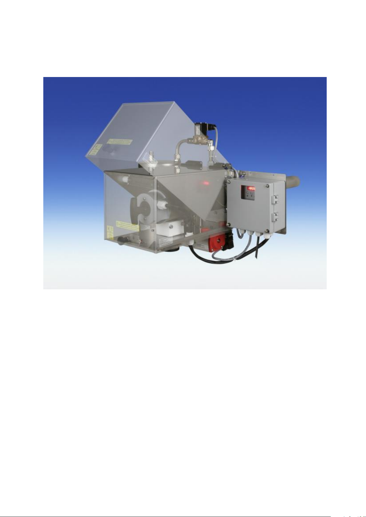
Installation- and Operation Instruction
Gasentnahmesonden / sample gas probe
Baureihe / Series 222.20-HT / 222.20-HT-OW-OR
Lesen Sie die Bedienungsanleitung vor dem Gebrauch des Gerätes gründlich durch. Beachten Sie
insbesondere die Hinweise unter Gliederungspunkt 2. Andernfalls könnten Gesundheits- oder
Sachschäden auftreten. Die Bühler Technologies GmbH haftet nicht bei eigenmächtigen
Änderungen des Gerätes oder für unsachgemäßen Gebrauch.
Read this instruction carefully prior to installation and/or use. Pay attention particularly to all
advises and safety instructions to prevent injuries. Bühler Technologies GmbH can not be held
responsible for misusing the product or unreliable function due to unauthorised modifications.
Page 2

Bedienungs- und Installationsanleitung
2
BX460026, 01/2011 Art. Nr. 90 31 181
Installation- and Operation Instruction
Gasentnahmesonden / sample gas probe
Baureihe / Series 222.20-HT / 222.20-HT-OW-OR
Inhaltsverzeichnis Seite
1 Einleitung ........................................................................................................................... 4
2 Wichtige Hinweise ............................................................................................................. 4
2.1 Allgemeine Gefahrenhinweise ........................................................................................................... 5
3 Erläuterungen zum Typenschild....................................................................................... 6
4 Produktbeschreibung ........................................................................................................ 7
4.1 Allgemeine Beschreibung .................................................................................................................. 7
4.2 Lieferumfang ..................................................................................................................................... 7
5 Transport und Lagerungsvorschriften ............................................................................. 8
6 Aufbauen und Anschließen ............................................................................................... 8
6.1 Montage ............................................................................................................................................. 8
6.2 Anschluss der Gasleitungen .............................................................................................................. 9
6.2.1 Anschluss der Gasentnahmeleitung.............................................................................................. 9
6.2.2 Anschluss des Kalibriergases (Option) ......................................................................................... 9
6.3 Elektrische Anschlüsse ................................................................................................................... 10
7 Betrieb und Wartung ....................................................................................................... 11
7.1 Allgemeine Warnhinweise ............................................................................................................... 11
7.2 Grundfunktion der Sondensteuerung bei GAS 222.20-HT .............................................................. 12
7.3 Wartung des Filterelementes .......................................................................................................... 12
7.3.1 Austrittsfilter Sonde GAS 222.20-HT-OW-OR ............................................................................ 12
7.3.2 Austrittsfilter Sonde GAS 222.20-HT ........................................................................................... 13
7.4 Bedienung der Steuerung ................................................................................................................ 13
7.4.1 Kurzerklärung des Bedienungsprinzips ....................................................................................... 13
7.4.2 Übersicht über die Menüführung ................................................................................................. 14
7.4.3 Ausführliche Erklärung des Bedienungsprinzips ......................................................................... 14
7.4.4 Beschreibung der Menüfunktionen .............................................................................................. 15
8 Fehlersuche und Beseitigung ......................................................................................... 16
8.1 Ersatzteil- und Verbrauchsmaterialliste ........................................................................................... 17
9 Instandsetzung und Entsorgung .................................................................................... 17
9.1 Entsorgung ...................................................................................................................................... 17
10 Zeichnungen, Bescheinigungen, Datenblätter .............................................................. 18
10.1 Anschlussdiagramm GAS 222.20-HT ............................................................................................. 18
10.2 Beigefügte Dokumente .................................................................................................................... 18
Page 3

Bedienungs- und Installationsanleitung
BX460026, 01/2011 Art. Nr. 90 31 181
3
Installation- and Operation Instruction
Gasentnahmesonden / sample gas probe
Baureihe / Series 222.20-HT / 222.20-HT-OW-OR
Content Page
1 Introduction ..................................................................................................................... 19
2 Important advice ............................................................................................................. 19
2.1 General Indication of Risk ............................................................................................................... 20
3 Explanation of the type plate ......................................................................................... 21
4 Product description ........................................................................................................ 21
4.1 General description ......................................................................................................................... 21
4.2 Scope of delivery ............................................................................................................................. 22
5 Transport and storing regulations ................................................................................. 22
6 Installation and connection ............................................................................................ 22
6.1 Mounting .......................................................................................................................................... 22
6.2 Connecting the gas tubes ................................................................................................................ 23
6.2.1 Connecting the sample gas tubes ............................................................................................... 23
6.2.2 Connecting the calibration gas tube (option) ............................................................................... 23
6.3 Electrical connection ....................................................................................................................... 24
7 Operation and Maintenance ........................................................................................... 25
7.1 Indication of risk .............................................................................................................................. 25
7.2 Basic functions of the controller for GAS 222.20-HT ...................................................................... 26
7.3 Maintenance of the filter element .................................................................................................... 26
7.3.1 Replacing the downstream filter for GAS 222.20-HT-OW-OR .................................................... 26
7.3.2 Replacing the downstream filter of probe GAS 222.20-HT ......................................................... 27
7.4 Operating the controller ................................................................................................................... 27
7.4.1 Short description of the operating principle ................................................................................. 27
7.4.2 Overview of the menu items ........................................................................................................ 28
7.4.3 Detailed description of the operating principle ............................................................................ 28
7.4.4 Description of the Menu Functions .............................................................................................. 29
8 Trouble shooting and elimination .................................................................................. 30
8.1 Spare parts and consumables......................................................................................................... 30
9 Repair and disposal ........................................................................................................ 31
9.1 Disposal ........................................................................................................................................... 31
10 Drawings, certificates, data sheets ............................................................................... 32
10.1 Wiring diagram GAS 222.20-HT ..................................................................................................... 32
10.2 Attached Documents ....................................................................................................................... 32
Page 4
Bedienungs- und Installationsanleitung
4
BX460026, 01/2011 Art. Nr. 90 31 181
HINWEIS
Signalwort für wichtige Information zum Produkt, auf die im besonderen Maße
aufmerksam gemacht werden soll.
VORSICHT
Signalwort zur Kennzeichnung einer Gefährdung mit geringem Risiko, die zu einem
Sachschaden oder leichten bis mittelschweren Verletzungen führen kann, wenn sie nicht
vermieden wird.
WARNUNG
Signalwort zur Kennzeichnung einer Gefährdung mit mittlerem Risiko, die möglicherweise
Tod oder schwere Verletzungen zur Folge hat, wenn sie nicht vermieden wird.
GEFAHR
Signalwort zur Kennzeichnung einer Gefährdung mit hohem Risiko, die unmittelbar Tod
oder schwere Verletzung zur Folge hat, wenn sie nicht vermieden wird.
Installation- and Operation Instruction
Gasentnahmesonden / sample gas probe
Baureihe / Series 222.20-HT / 222.20-HT-OW-OR
1 Einleitung
Die Gasentnahmesonden der Baureihe GAS 222.xx sind zum Einbau in Gasanalysesystemen bestimmt.
Gasentnahmesonden gehören zu den wichtigsten Bauteilen eines Gasaufbereitungssystems. Bitte
beachten Sie deshalb auch die dazugehörige Zeichnung am Ende dieser Anleitung (Kap. 10) und
überprüfen Sie vor Einbau der Gasentnahmesonden, ob die genannten technischen Daten den
Anwendungsparametern entsprechen. Überprüfen Sie ebenfalls, ob alle zum Lieferumfang gehörenden
Teile vollständig vorhanden sind.
Diese Bedienungsanleitung beschreibt mehrere Sondentypen aus der GAS 222.xx - Reihe zusammen, da
viele Beschreibungen gleich oder ähnlich sind (siehe Kap. 4.1).
Welche Sonde Sie vor sich haben, ersehen Sie aus dem Typenschild. Auf diesem finden Sie neben der
Auftragsnummer auch die Artikelnummer und Typbezeichnung.
Sofern für einen Sondentyp Besonderheiten gelten, sind diese in der Bedienungsanleitung gesondert
beschrieben.
Bitte beachten Sie beim Anschluss die Kennwerte der Sonde und bei Ersatzteilbestellungen die richtigen
Ausführungen.
2 Wichtige Hinweise
Der Einsatz der Sonde ist nur zulässig, wenn:
- das Produkt unter den in der Bedienungs- und Installationsanleitung beschriebenen Bedingungen, dem
Einsatz gemäß Typenschild und für Anwendungen, für die es vorgesehen ist, verwendet wird.
- die im Datenblatt und der Anleitung angegebenen Grenzwerte eingehalten werden.
- Überwachungsvorrichtungen/ Schutzvorrichtung korrekt angeschlossen sind.
- die Service- und Reparaturarbeiten, die nicht in dieser Anleitung beschrieben sind, von Bühler
Technologies GmbH durchgeführt werden.
- Originalersatzteile verwendet werden.
Diese Bedienungsanleitung ist Teil des Betriebsmittels. Der Hersteller behält sich das Recht vor, die
Leistungs-, die Spezifikations- oder die Auslegungsdaten ohne Vorankündigung zu ändern. Bewahren Sie
die Anleitung für den späteren Gebrauch auf.
Signalwörter für Warnhinweise:
Page 5
Bedienungs- und Installationsanleitung
BX460026, 01/2011 Art. Nr. 90 31 181
5
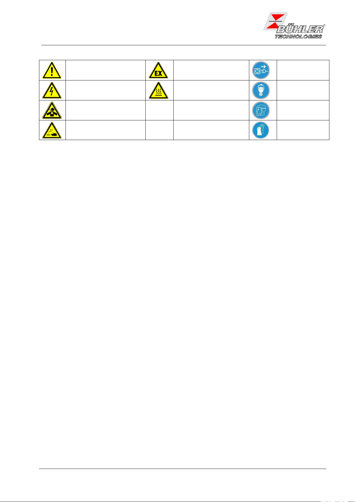
Warnung vor einer
allgemeinen Gefahr
Warnung vor explosionsgefährdeten Bereichen
Netzstecker
ziehen
Warnung vor elektrischer
Spannung
Warnung vor heißer
Oberfläche
Atemschutz
tragen
Warnung vor dem
Einatmen giftiger Gase
Gesichtsschutz
tragen
Warnung vor ätzenden
Flüssigkeiten
Handschuhe
tragen
Installation- and Operation Instruction
Gasentnahmesonden / sample gas probe
Baureihe / Series 222.20-HT / 222.20-HT-OW-OR
In dieser Anleitung werden folgende Warnzeichen und Signalwörter benutzt:
2.1 Allgemeine Gefahrenhinweise
Das Gerät darf nur von Fachpersonal installiert werden, das mit den Sicherheitsanforderungen und den
Risiken vertraut ist.
Beachten Sie unbedingt die für den Einbauort relevanten Sicherheitsvorschriften und allgemein gültigen
Regeln der Technik. Beugen Sie Störungen vor und vermeiden Sie dadurch Personen- und Sachschäden.
Der für die Anlage Verantwortliche muss sicherstellen, dass:
- Sicherheitshinweise und Betriebsanleitungen verfügbar sind und eingehalten werden,
- Unfallverhütungsvorschriften der Berufsgenossenschaften beachtet werden; in Deutschland:
Allgemeine Vorschriften” (VBG 1) und “Elektrische Anlagen und Betriebsmittel (VBG 4)”,
- die zulässigen Daten und Einsatzbedingungen eingehalten werden,
- Schutzeinrichtungen verwendet werden und vorgeschriebene Wartungsarbeiten durchgeführt werden,
- bei der Entsorgung die gesetzlichen Regelungen beachtet werden.
Wartung, Reparatur:
- Reparaturen an den Betriebsmitteln dürfen nur von Bühler autorisiertem Personal ausgeführt werden.
- Nur Umbau-, Wartungs- oder Montagearbeiten ausführen, die in dieser Bedienungs- und
Installationsanleitung beschrieben sind.
- Nur Original-Ersatzteile verwenden.
Bei Durchführung von Wartungsarbeiten jeglicher Art müssen die relevanten Sicherheits- und
Betriebsbestimmungen beachtet werden.
Page 6
Bedienungs- und Installationsanleitung
6
BX460026, 01/2011 Art. Nr. 90 31 181
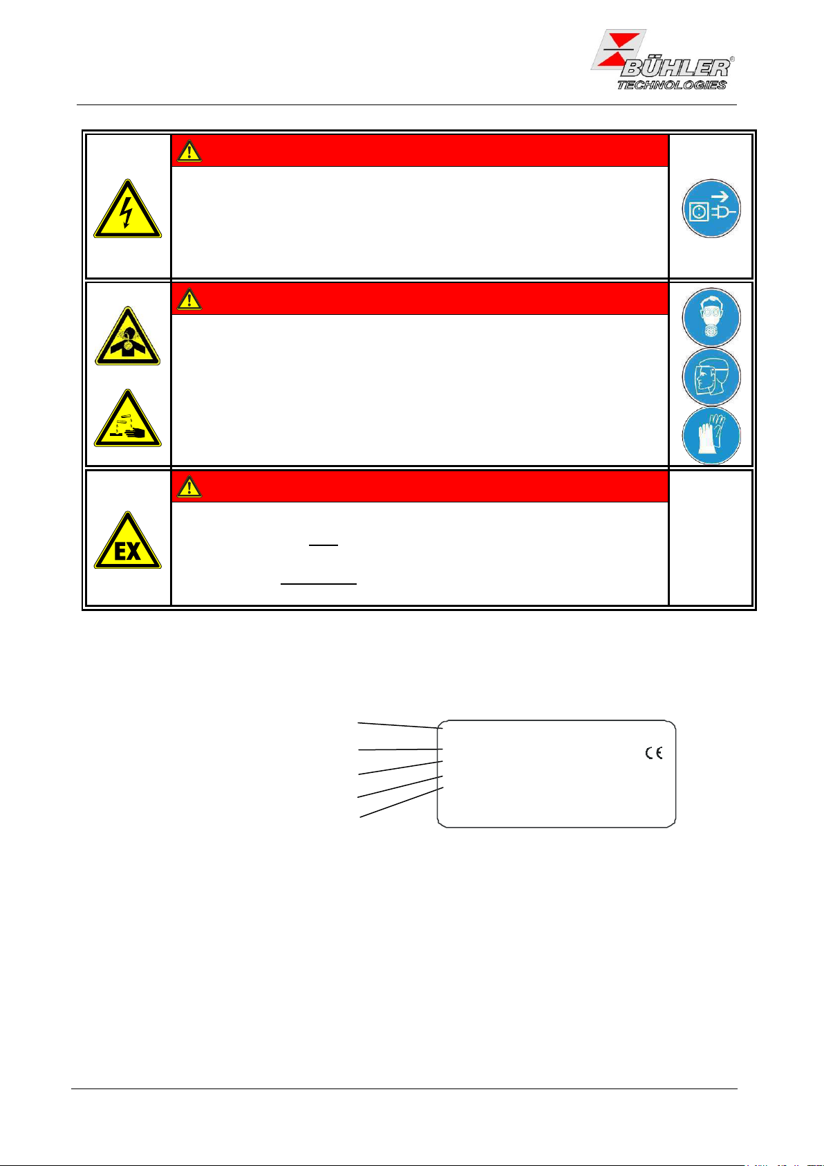
GEFAHR
Elektrische Spannung
Gefahr eines elektrischen Schlages.
Trennen Sie das Gerät bei allen Arbeiten vom Netz. Sichern Sie das Gerät
gegen unbeabsichtigtes Wiedereinschalten.
Das Gerät darf nur von instruiertem, fachkundigem Personal geöffnet werden.
GEFAHR
Giftige, ätzende Gase
Messgas kann gesundheitsgefährdend sein.
Bitte sorgen Sie ggf. für eine sichere Ableitung des Gases.
Schützen Sie sich bei der Wartung vor giftigen / ätzenden Gasen. Tragen Sie
die entsprechende Schutzausrüstung.
GEFAHR
Explosionsgefahr bei Verwendung in Explosionsgefährdeten Bereichen
Das Betriebsmittel ist nicht für den Einsatz in explosionsgefährdeten Bereichen
geeignet.
Durch das Gerät dürfen keine zündfähigen oder explosiven Gasgemische
geleitet werden.
Auftrags-Nr., Artikel-Nr.
Hersteller mit Anschrift
Typbezeichnung
Werkstoff
Spannung
Bühler Technologies GmbH
Harkortstr.29, D-40880 Ratingen
A000248D
GAS 222.20-HT
200908240007 4622220HT
230V 50/60Hz 440W
1.4571
READ MANUAL!
Installation- and Operation Instruction
Gasentnahmesonden / sample gas probe
Baureihe / Series 222.20-HT / 222.20-HT-OW-OR
3 Erläuterungen zum Typenschild
Page 7

Bedienungs- und Installationsanleitung
BX460026, 01/2011 Art. Nr. 90 31 181
7
Installation- and Operation Instruction
Gasentnahmesonden / sample gas probe
Baureihe / Series 222.20-HT / 222.20-HT-OW-OR
4 Produktbeschreibung
4.1 Allgemeine Beschreibung
Diese Bedienungs- und Installationsanleitung gilt für die Gasentnahmesonden GAS 222.xx.
In dieser Bedienungsanleitung wird auf die verschiedenen Sondentypen in Unterabschnitten mit ihrer
Typennummer eingegangen. Diese Nummer finden Sie auf dem Typenschild. Sie beginnt immer mit GAS
222. und anschließend folgt die Typnummer; z.B. GAS 222.22-HT.
Vorab eine Kurzzusammenfassung der Sondentypen:
Eintrittsfilter (Filter im Prozess), Austrittsfilter (Filter in der Sonde)
GAS 222.20-HT-OW-OR Sonde mit Austrittsfilter, ohne Wetterschutzhaube, ohne elektronischen
Regler
GAS 222.20-HT Sonde mit Austrittsfilter, mit Wetterschutzhaube, elektronischer Regler bis
280°C
Zubehör zu diesen Sonden: Die Gasentnahmesonden können - je nach Bestellung- mit verschiedenen ab
Werk angebautem Zubehör ausgeliefert sein. Dieses Zubehör ist ebenso wie das separat mitgelieferte
Zubehör als gesonderte Position im Auftrag ausgewiesen. Siehe auch Datenblatt DD461099
4.2 Lieferumfang
1x Gasentnahmesonde
1x Flanschdichtung und Schrauben
1x Bedienungsanleitung
Angebaute und beiliegende Zubehörteile sind als gesonderte Position im Auftrag ausgewiesen.
Page 8
Bedienungs- und Installationsanleitung
8
BX460026, 01/2011 Art. Nr. 90 31 181
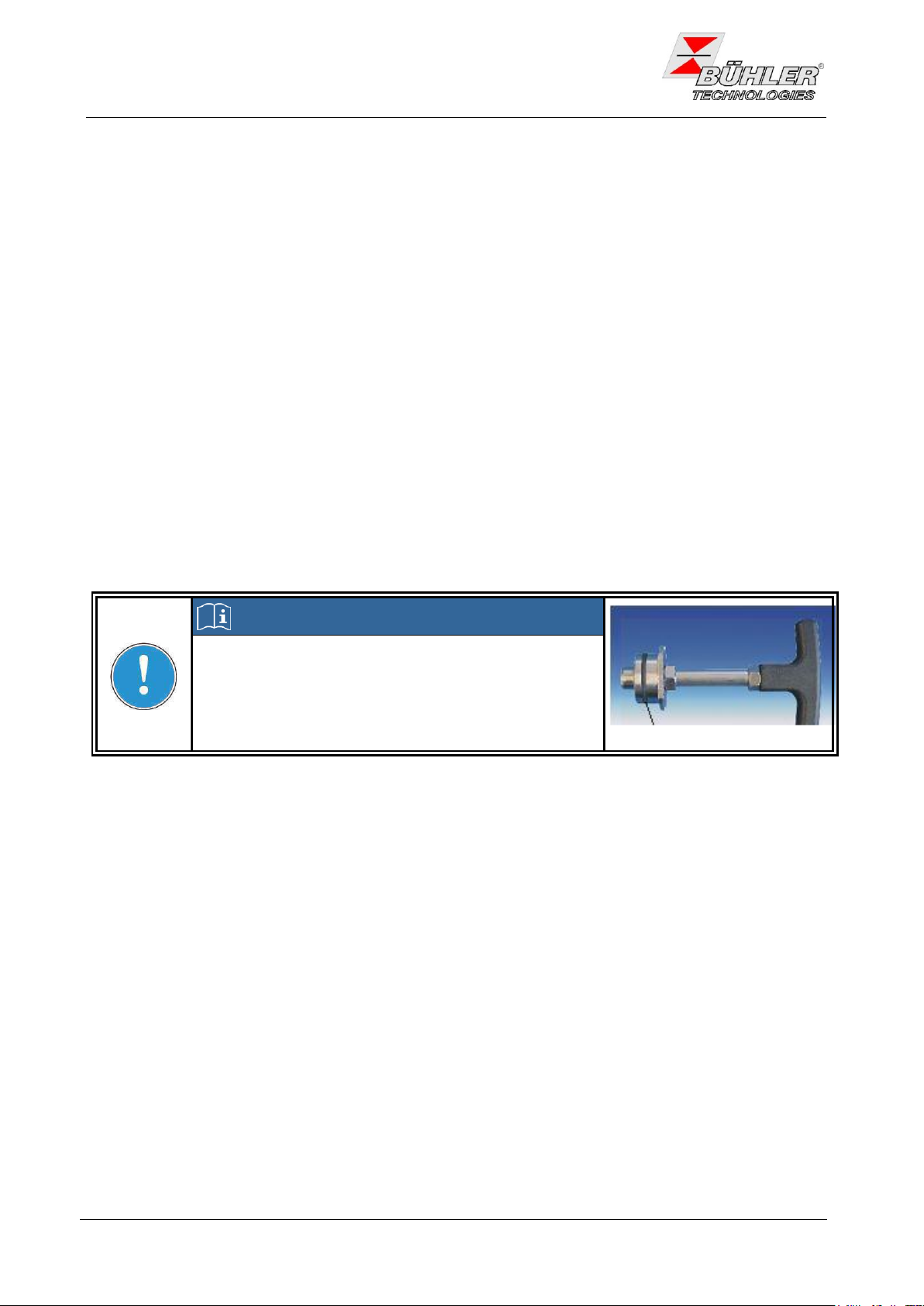
HINWEIS
Der Austrittsfilter und der O-Ring für das Griffstück sind
lose beigelegt und müssen vor Inbetriebnahme eingesetzt
werden.
Betrieb ohne Austrittsfilter nicht zulässig!
Installation- and Operation Instruction
Gasentnahmesonden / sample gas probe
Baureihe / Series 222.20-HT / 222.20-HT-OW-OR
5 Transport und Lagerungsvorschriften
Die Gasentnahmesonde nur in der Originalverpackung oder einem geeigneten Ersatz transportieren.
Bei längerer Nichtbenutzung ist die Gasentnahmesonde gegen Feuchtigkeit und Wärme zu schützen.
Die Gasentnahmesonde muss in einem überdachten, trockenen, vibrations- und staubfreien Raum bei
einer Temperatur von -20°C bis +60°C aufbewahrt werden.
6 Aufbauen und Anschließen
6.1 Montage
Die Gasentnahmesonden sind zur Flanschmontage vorgesehen. Einbauort und Einbaulage bestimmen sich
aus anwendungsrelevanten Voraussetzungen. Falls möglich, sollte der Einbaustutzen eine leichte Neigung
zur Kanalmitte haben. Der Einbauort sollte wettergeschützt sein.
Ebenfalls muss auf ausreichenden und sicheren Zugang sowohl für die Installation als auch für spätere
Wartungsarbeiten geachtet werden. Beachten Sie hier insbesondere die Ausbaulänge des Sondenrohres!
Soweit die Sonde in Einzelteilen zum Einbauort gebracht wird, muss sie zunächst zusammengebaut
werden.
Das Entnahmerohr, falls erforderlich mit der passenden Verlängerung, muss eingeschraubt werden.
Danach wird die Sonde unter Verwendung der beigefügten Dichtungen und Schrauben am Gegenflansch
befestigt.
Bei beheizten Sonden sind die blank liegenden Flanschteile und ggf. der Einbaustutzen nach der Montage
vollständig zu isolieren, damit Kältebrücken unbedingt vermieden werden. Das Isoliermaterial muss den
Anwendungsvoraussetzungen entsprechen und wetterfest sein.
Page 9
Bedienungs- und Installationsanleitung
BX460026, 01/2011 Art. Nr. 90 31 181
9
VORSICHT
Bruchgefahr
Das Isoliermaterial kann zerbrechen. Vorsichtig behandeln, nicht fallen lassen.
WARNUNG
Gasaustritt
Messgas kann gesundheitsschädlich sein.
Prüfen Sie die Leitungen auf Dichtheit.
Installation- and Operation Instruction
Gasentnahmesonden / sample gas probe
Baureihe / Series 222.20-HT / 222.20-HT-OW-OR
6.2 Anschluss der Gasleitungen
6.2.1 Anschluss der Gasentnahmeleitung
Die Messgasleitung ist mittels der montierten Verschraubung sorgfältig und fachgerecht anzuschließen.
Dies gilt auch bei allen Sonden für die Option Prüfgasanschluss.
Für den Anschluss der Messgasleitung (Durchmesser 6) sind bei den beheizten Sonden folgende Punkte
zu beachten, um Kältebrücken zu vermeiden: Kürzen Sie das Anschlussrohr der Messgasleitung soweit wie
möglich. Die Isolierbacken im Bereich der Messgasleitung sind zu entfernen. Dies geschieht durch Lösen
der Befestigungsschrauben.
Nach Anschluss der Messgasleitung ist diese durch die Schelle abzufangen und zu sichern
(GAS 222.20-HT).
Bei längeren Messgasleitungen sind unter Umständen weitere Sicherungsschellen auf dem Weg zum
Analysensystem vorzusehen! Nach dem alle Leitungen angeschlossen und auf Dichtheit überprüft wurden,
wird die Isolation wieder sorgfältig eingesetzt und gesichert.
6.2.2 Anschluss des Kalibriergases (Option)
Zum Anschluss der Kalibriergasleitung wird eine Rohrverschraubung ø6 mm benötigt.
Ist der Kalibriergasanschluss mit einem Rückschlagventil bestellt worden, kann an dem Rückschlagventil
direkt ein Rohr ø6mm angeschlossen werden.
Page 10
Bedienungs- und Installationsanleitung
10
BX460026, 01/2011 Art. Nr. 90 31 181
WARNUNG
Gefahr eines elektrischen Schlages
Der Anschluss darf nur von geschultem Fachpersonal vorgenommen werden.
VORSICHT
Falsche Netzspannung kann das Gerät zerstören
Bei Anschluss auf die richtige Netzspannung gemäß Typenschild achten.
Achten Sie auf ausreichende Zugentlastung der Anschlusskabel.
WARNUNG
Beschädigung des Gerätes bei Durchführung der Isolationsprüfung
Führen Sie keine Prüfung der Spannungsfestigkeit mit Hochspannung am
Gesamtgerät durch!
WARNUNG
Brandgefahr / Gasaustritt
Beschädigung des Gerätes bei Beheizung der Sonde auf > 280°C
Bei Beheizung der Sonde auf > 280°C kann es zu Beschädigungen an
Dichtungen, Kabeln und der Wärmeisolation kommen. Dies kann zu
Gasaustritt oder einem Brand führen.
Sonde darf nicht auf Temperaturen > 280°C beheizt werden
Installation- and Operation Instruction
Gasentnahmesonden / sample gas probe
Baureihe / Series 222.20-HT / 222.20-HT-OW-OR
6.3 Elektrische Anschlüsse
Das Gerät ist mit umfangreichen EMV-Schutzmaßnahmen ausgerüstet. Bei einer Prüfung der Spannungsfestigkeit werden elektronische Filterbauteile beschädigt. Die notwendigen Prüfungen wurden bei allen zu
prüfenden Baugruppen werkseitig durchgeführt (Prüfspannung je nach Bauteil 1 kV bzw. 1,5 kV).
Sofern Sie die Spannungsfestigkeit selbst nochmals prüfen wollen, führen Sie diese nur an den
entsprechenden Einzelkomponenten durch.
Klemmen Sie die Heizung der Sonde ab (siehe Anschlussbelegung im Anhang). Führen Sie nun die
Spannungsfestigkeitsprüfung gegen Erde durch.
Die Sonde darf bei maximaler Umgebungstemperatur von 45°C über den Sondenregler max. auf 280°C
beheizt werden. Bei Überschreiten von 300°C Sondentemperatur erfolgt über den angebauten Regler eine
Notabschaltung der Sonde (=>keine Heizleistung). Im Display wird „Error“ angezeigt. In diesem Fall muss
die Versorgungsspannung der Sonde unterbrochen und das Gerät zur Wartung dem Hersteller zugesandt
werden.
Diese Sonden haben eine regelbare, einstellbare Beheizung. Der Regler ist nicht im Lieferumfang
enthalten. Die Anschlussspannung ist 115 V AC, 50/60 Hz oder 230 V AC, 50/60 Hz (siehe Typenschild).
Bei der Einstellung des externen Reglers ist darauf zu achten, dass die maximale Betriebstemperatur von
280°C nicht überschritten wird.
Falls es applikationsbedingt zu sehr starker Wärmeabstrahlung im Bereich der Sonde kommt, ist bauseits
eine entsprechende Abschirmung zum Schutz von Sonde anzubringen.
Page 11
Bedienungs- und Installationsanleitung
BX460026, 01/2011 Art. Nr. 90 31 181
11
GEFAHR
Elektrische Spannung
Gefahr eines elektrischen Schlages.
Trennen Sie das Gerät bei allen Arbeiten vom Netz. Sichern Sie das Gerät
gegen unbeabsichtigtes Wiedereinschalten.
Der Anschluss darf nur von geschultem Fachpersonal vorgenommen werden.
Achten Sie auf die korrekte Spannungsversorgung!
GEFAHR
Giftige, ätzende Gase
Messgas kann gesundheitsgefährdend sein.
Die Sonde darf beim Öffnen nicht unter Druck bzw. Spannung stehen.
Bitte sorgen Sie ggf. für eine sichere Ableitung des Gases.
Schützen Sie sich bei der Wartung, insbesondere beim Filterwechsel vor
giftigen / ätzenden Gasen. Tragen Sie die entsprechende Schutzausrüstung.
Spülen Sie die Gasleitungen mit Luft.
VORSICHT
Heiße Oberfläche
Verbrennungsgefahr
Im Betrieb kann je nach Betriebsparametern und Typ eine Gehäusetemperatur
von bis zu 100°C entstehen.
Lassen Sie das Gerät erst abkühlen, bevor Sie mit den Wartungsarbeiten
beginnen.
VORSICHT
Überdruck
Die Sonde darf beim Öffnen nicht unter Druck bzw. Spannung stehen.
Schließen Sie vor dem Öffnen die Gaszufuhr.
Installation- and Operation Instruction
Gasentnahmesonden / sample gas probe
Baureihe / Series 222.20-HT / 222.20-HT-OW-OR
7 Betrieb und Wartung
7.1 Allgemeine Warnhinweise
Beachten Sie vor der Inbetriebnahme:
- Die Gasentnahmesonde darf nicht außerhalb ihrer Spezifikationen betrieben werden.
- Beachten Sie die Sicherheitshinweise vor der ersten Inbetriebnahme.
- Reparaturen an den Betriebsmitteln dürfen nur von Bühler autorisiertem Personal ausgeführt werden.
- Führen Sie nur Umbau-, Wartungs- oder Montagearbeiten aus, die in dieser Bedienungs- und
Installationsanleitung beschrieben sind.
- Verwenden Sie nur Original-Ersatzteile.
- Beachten Sie bei der Durchführung von Wartungsarbeiten jeglicher Art die relevanten Sicherheits- und
Betriebsbestimmungen.
Page 12
Bedienungs- und Installationsanleitung
12
BX460026, 01/2011 Art. Nr. 90 31 181
HINWEIS
Die Keramikfilterelemente sind von ihrer Beschaffenheit sehr zerbrechlich. Daher die
Elemente vorsichtig handhaben und nicht fallen lassen.
Die Filterelemente aus Edelstahl können in einem Ultraschallbad gereinigt und öfters
wiederverwendet werden, in diesem Falle verwenden Sie auf jeden Fall neue Dichtungen an
Filter und Griffstopfen.
Installation- and Operation Instruction
Gasentnahmesonden / sample gas probe
Baureihe / Series 222.20-HT / 222.20-HT-OW-OR
7.2 Grundfunktion der Sondensteuerung bei GAS 222.20-HT
Nach Einschalten der Kombination wird die Sonde aufgeheizt. Am Regler leuchtet die Anzeige mit der
aktuellen Temperatur auf. Solange der eingestellte Arbeitsbereich (siehe Einstellung der Parameter, Kapitel
7.4) noch nicht erreicht ist, blinkt die Anzeige und der Statuskontakt ist in der Stellung Alarm. Wenn der
Arbeitsbereich erreicht wird, schaltet der Statuskontakt um und die Anzeige ist dauerhaft.
Die Solltemperatur, der Arbeitsbereich der Sonde und die Temperatureinheit (°C/°F) werden mittels der drei
Bedientasten der Steuerung eingestellt. Dies ist im Kapitel 7.4 „Bedienen der Steuerung“ beschrieben.
Die Werkseinstellungen sind: Einheit: °C; Solltemperatur: 260 °C; Arbeitsbereich: ±10 °C
7.3 Wartung des Filterelementes
Die Sonden sind mit einem Partikelfilter ausgerüstet, der je nach Schmutzanfall gewechselt werden muss.
7.3.1 Austrittsfilter Sonde GAS 222.20-HT-OW-OR
Gaszufuhr abstellen, ggf. Prozess abschalten.
Den Griff am hinteren Ende der Sonde unter leichtem Eindrücken um 90° drehen (Griff muss dann
waagerecht stehen) und herausziehen.
Das verschmutzte Filterelement abziehen und die Dichtflächen kontrollieren.
Vor Aufstecken des neuen Filterelementes, die Dichtung am Griffstopfen (Dichtung gehört zum
Lieferumfang des Filterelementes) erneuern.
Bei herausgenommenem Filter kann erforderlichenfalls auch das Entnahmerohr durch Ausblasen
oder mittels eines Reinigungsstabes von innen gereinigt werden.
Den Griff dann mit neuem Filter einführen und unter leichtem Eindrücken um 90° drehen (Griff
muss dann senkrecht stehen).
Achtung: Hintere Filteraufnahme nicht beschädigen!
Page 13
Bedienungs- und Installationsanleitung
BX460026, 01/2011 Art. Nr. 90 31 181
13
HINWEIS
Die Wetterschutzhaube lässt sich nur wieder schließen, wenn der Griff vollständig in der
Senkrechten steht. Dazu die Haube durch leichtes Anheben aus der Verriegelungsstütze
lösen und dann herunterklappen. Auf richtiges Einrasten der Haubenverriegelung achten.
Taste
Funktionen
j
Wechsel von der Messwertanzeige ins Hauptmenü
Auswahl des angezeigten Menüpunktes
Annahme eines editierten Wertes oder einer Auswahl
t
Wechsel zum oberen Menüpunkt
Erhöhen der Zahl beim Ändern eines Wertes oder Wechseln der Auswahl
temporärer Wechsel zur alternativen Messwertanzeige (wenn Option
vorhanden)
b
Wechsel zum unteren Menüpunkt
Erniedrigen der Zahl beim Ändern eines Wertes oder Wechseln der Auswahl
temporärer Wechsel zur alternativen Messwertanzeige (wenn Option
vorhanden)
Installation- and Operation Instruction
Gasentnahmesonden / sample gas probe
Baureihe / Series 222.20-HT / 222.20-HT-OW-OR
7.3.2 Austrittsfilter Sonde GAS 222.20-HT
Bei diesen Sonden ist vor dem Filterwechsel die Wetterhaube zu entriegeln und aufzustellen.
Der Filterwechsel erfolgt dann wie unter wie unter 7.3.1 beschrieben.
7.4 Bedienung der Steuerung
7.4.1 Kurzerklärung des Bedienungsprinzips
Benutzen Sie diese Kurzerklärung nur, wenn Sie bereits Erfahrung im Bedienen des Sondenreglers
besitzen. Eine ausführliche Erklärung erhalten Sie in den nachfolgenden Unterkapiteln.
Tasten:
Die Bedienung erfolgt mit nur 3 Tasten. Sie haben je nach Kontext folgende Funktionen:
Page 14

Bedienungs- und Installationsanleitung
14
BX460026, 01/2011 Art. Nr. 90 31 181
Anzeige der Temperatur und des Betriebszustandes
Sondenregler
Anzeige:
Prob
50°C...280°C
Anzeige:
xxxx
±5°C...±30°C
Anzeige: xxx
Exit Hauptmenü
Anzeige: E
Exit Untermenü
Anzeige: E
j
Hauptmenü
Solltemperatur
Anzeige:
tEMP
Untermenü
Alarmhysterese
Anzeige: ALAr
Einstellbereich
j
j
t b
t b
j
j
j
aktuelle Temperatur
Anzeige:
xxxx
Angezeigt wird die Sondentemperatur in 0,5°C Schritten. Durch Betätigen der Enter Taste j gelangt man ins
Hauptmenü. Die Temperatur kann wahlweise in Celsius oder in Fahrenheit dargestellt werden.
Einstellung der
Sondentemperatur im
Bereich: 50°C...280°C
Setzen der
Alarmhysterese im
Bereich: ±5°C...±30°C
t b Wert einstellen
j speichert den Wert
warte 4s: kein Speichern
t b
VD 00 0010
Installation- and Operation Instruction
Gasentnahmesonden / sample gas probe
Baureihe / Series 222.20-HT / 222.20-HT-OW-OR
7.4.2 Übersicht über die Menüführung
7.4.3 Ausführliche Erklärung des Bedienungsprinzips
Die ausführliche Erklärung führt Sie Schritt für Schritt durch das Menü der Sondensteuerung.
Schließen Sie die Sonde an die Stromversorgung an und warten Sie die Einschaltprozedur ab. Zu
Beginn wird für kurze Zeit die im Gerät implementierte Software-Version angezeigt. Anschließend
geht das Gerät direkt zur Messwertanzeige über.
Durch Drücken der Taste j gelangt man vom Anzeigemodus ins Hauptmenü. (Es ist
gewährleistet, dass die Sondensteuerung auch im Menübetrieb weiter läuft.)
Man navigiert mit den Tasten t b gemäß Übersicht über die Menüführung durch das Hauptmenü.
Bestätigt man einen Hauptmenüeintrag (j), wird das zugehörige Untermenü aufgerufen.
Im Untermenü können Betriebsparameter eingestellt werden. Zum Einstellen der Parameter
durchläuft man das Untermenü mit den Tasten t b und bestätigt mit j den einzustellenden
Menüpunkt.
Nun können die Werte innerhalb bestimmter Grenzen durch Betätigen der t b Tasten verstellt
werden. Bestätigt man die Einstellung mit j, wird der eingestellte Wert vom System gespeichert.
Im Anschluss gelangt man automatisch zurück ins Untermenü.
Da ein manuelles Rückspringen aus den einstellbaren Bereichen nicht vorgesehen ist, kann einfach
einige Sekunden gewartet werden. Das System wechselt dann zurück ins Untermenü, ohne die
Werte zu speichern.
Ähnlich verhält es sich mit dem Unter- oder auch mit dem Hauptmenü. Falls vergessen wird, das
Menü regulär zu verlassen, wechselt das System selbstständig zurück in den Anzeigemodus. Dabei
werden hier allerdings die zuvor gespeicherten Parameter beibehalten und die verstellten Werte
werden nicht übernommen. Hinweis: Sobald Werte mit der Enter-Taste gespeichert werden,
werden diese für die Reglung übernommen.
Verlassen des Haupt- bzw. Untermenüs erfolgt durch Auswahl des Menüpunktes E (Exit).
Page 15

Bedienungs- und Installationsanleitung
BX460026, 01/2011 Art. Nr. 90 31 181
15
Probe:
Von hier aus gelangt man zu allen relevanten Einstellmöglichkeiten des
Temperaturreglers für die Sonde. Im zugehörigen Untermenü können
Solltemperatur und die Alarmschwellen ausgewählt werden.
Top settings
Auswahl der globalen Temperatureinheit. Wahlweise Grad Celsius (C) oder
Grad Fahrenheit (F).
Hinweis:
Zu diesem Hauptmenüpunkt gibt es keinen Untermenüpunkt. Es kann von hier
aus direkt die Temperatureinheit ausgewählt werden.
Exit
Durch Auswählen gelangt man zurück in den Anzeigemodus.
Temperature
Diese Einstellung setzt den Sollwert für die Sondentemperatur. Der Wert kann in
einem Bereich von 50°C bis 280°C gesetzt werden.
Hinweis:
Der Standardwert bei Auslieferung beträgt 180°C.
Alarm range
Hier kann der Bereich für den optischen Alarm sowie für das Alarmrelais gesetzt
werden. Eingestellt wird die Alarmgrenze im Bereich von ±5°C (±9°F) bis ±30°C
(±54°F) um den Sollwert.
Hinweis:
Der Standardwert bei Auslieferung beträgt ±10°C (±18°F).
Exit
Durch Auswählen gelangt man zurück ins Hauptmenü.
Installation- and Operation Instruction
Gasentnahmesonden / sample gas probe
Baureihe / Series 222.20-HT / 222.20-HT-OW-OR
7.4.4 Beschreibung der Menüfunktionen
7.4.4.1 Hauptmenü
Sondenregler (Probe)
Globale Einstellungen (Top settings)
Exit Hauptmenü
7.4.4.2 Untermenü Sondenregler (Anzeige: Prob)
Sondenregler
Sondenregler Alarmbereich
Exit Untermenü
Solltemperatur
Page 16

Bedienungs- und Installationsanleitung
16
BX460026, 01/2011 Art. Nr. 90 31 181
Problem / Störung
mögliche Ursache
Abhilfe
Kein bzw. verminderter
Gasfluss
- Filterelement verstopft
- Filterelement reinigen bzw.
austauschen, Entnahmerohr reinigen
Temperaturalarm
- Aufheizphase noch nicht
beendet
- Aufheizphase abwarten
- PT 100 defekt
- Sonde zur Reparatur einschicken
- Heizung / Regler defekt
- Sonde zur Reparatur einschicken
Keine Heizleistung/
Keine Anzeige
- Keine / falsche
Spannungsversorgung
- Spannungsversorgung überprüfen
- Regler defekt
- Sonde zur Reparatur einschicken
Kondensatbildung
- Heizung defekt
- Sonde zur Reparatur einschicken
- Kältebrücken an der
Entnahmestelle
- Kältebrücken durch Isolierung
beseitigen
Fehlermeldung im Display
Error 01
- Sondentemperatur zu hoch,
Leitung PT100 unterbrochen
- Anschluss PT100 im Regler
überprüfen bzw. Sonde zur Reparatur
einschicken
Error 02
- Sondentemperatur zu niedrig,
PT100 Kurzschluss
- Sonde zur Reparatur einschicken
Installation- and Operation Instruction
Gasentnahmesonden / sample gas probe
Baureihe / Series 222.20-HT / 222.20-HT-OW-OR
8 Fehlersuche und Beseitigung
Page 17

Bedienungs- und Installationsanleitung
BX460026, 01/2011 Art. Nr. 90 31 181
17
Sonde
Filter
Beschreibung
Artikel-Nr.
GAS 222.xx
Sicherung
115V / 230V: 800 mA träge
91 100 000 01
GAS 222.xx
AHF-22-x
Dichtung für Messausgang
90 091 05
Flanschdichtung DN65 PN6
90 090 79
Flachdichtung FD 40 WS
90 090 68
O-Ring für Verschlussstück, Material Kalrez
90 093 93
O-Ring für Filterelement (2 Stk. erforderlich), Material
Kalrez
90 093 94
Filterelemente Edelstahl
46 222 010 PHT
Filterelemente Keramik gesintert
46 222 026 HT
Installation- and Operation Instruction
Gasentnahmesonden / sample gas probe
Baureihe / Series 222.20-HT / 222.20-HT-OW-OR
8.1 Ersatzteil- und Verbrauchsmaterialliste
Bei Ersatzteilbestellungen bitten wir Sie, Kühlertyp und Seriennummer anzugeben.
Bauteile für Nachrüstung und Erweiterung finden Sie im angehängten Datenblatt und in unserem Katalog.
Die folgenden Ersatzteile sollten vorgehalten werden:
9 Instandsetzung und Entsorgung
Sollte ein Fehler beim Betrieb auftreten, finden Sie unter Gliederungspunkt 8. Fehlersuche und Beseitigung.
Sollten Sie weitere Fragen haben, wenden Sie sich bitte an unseren Service
Tel.: +49-(0)2102-498955 oder Ihre zuständige Vertretung.
Ist nach Beseitigung eventueller Störungen und nach Einschalten der Netzspannung die korrekte Funktion
nicht gegeben, muss das Gerät durch den Hersteller überprüft werden. Bitte senden Sie das Gerät zu
diesem Zweck in geeigneter Verpackung an:
Bühler Technologies GmbH
- Reparatur/Service Harkortstraße 29
40880 Ratingen
Deutschland
Bringen Sie zusätzlich die Dekontaminierungserklärung ausgefüllt und unterschrieben an der Verpackung
an. Ansonsten ist eine Bearbeitung Ihres Reparaturauftrages nicht möglich! Das Formular kann per E-Mail
angefordert werden: service@buehler-technologies.com.
9.1 Entsorgung
Bei der Entsorgung sind die gesetzlichen und Normenregelungen im Anwenderland zu beachten.
Page 18

Bedienungs- und Installationsanleitung
18
BX460026, 01/2011 Art. Nr. 90 31 181
S
t
a
t
u
s
S
o
n
d
e
n
t
e
m
p
e
r
a
t
u
r
/
p
r
o
b
e
t
e
m
p
e
r
a
t
u
r
e
H
e
i
z
u
n
g
S
o
n
d
e
/
h
e
a
t
e
r
p
r
o
b
e
H
e
i
z
u
n
g
P
A
V
/
h
e
a
t
e
r
P
A
V
P
t
1
0
0
b
e
h
e
i
z
t
e
V
e
r
l
ä
n
g
e
r
u
n
g
/
h
e
a
t
e
d
e
x
t
e
n
s
i
o
n
S
p
a
n
n
u
n
g
s
v
e
r
s
o
r
g
u
n
g
E
r
w
e
i
t
e
r
u
n
g
/
p
o
w
e
r
s
u
p
p
l
y
a
d
d
-
o
n
P
t
1
0
0
S
o
n
d
e
/
p
r
o
b
e
Netz/power
Mainboard
L
L
L
N
N
N
PE
PE
A000234X
Bei angeschlossener beheizten
Verlängerung Brücke entfernen/
if a heated extension is connected
remove bridge circuit
L
N
Installation- and Operation Instruction
Gasentnahmesonden / sample gas probe
Baureihe / Series 222.20-HT / 222.20-HT-OW-OR
10 Zeichnungen, Bescheinigungen, Datenblätter
10.1 Anschlussdiagramm GAS 222.20-HT
10.2 Beigefügte Dokumente
- Zeichnung Gasentnahmesonde GAS 222.20-HT-OW-OR (46/L78-Z01-01-3)
- Zeichnung Gasentnahmesonde GAS 222.20-HAT (46/126-Z01-01-3)
- Konformitätserklärung KX460019
- Datenblatt DD461720
- Dekontaminierungserklärung
Page 19

Bedienungs- und Installationsanleitung
BX460026, 01/2011 Art. Nr. 90 31 181
19
NOTE
Signal word for important information to the product
CAUTION
Signal word for a hazardous situation with low risk, resulting in damage to the device or
the property or minor or medium injuries if not avoided.
WARNING
Signal word for a hazardous situation with medium risk, possibly resulting in severe
injuries or death if not avoided.
DANGER
Signal word for an imminent danger with high risk, resulting in severe injuries or death if
not avoided
Installation- and Operation Instruction
Gasentnahmesonden / sample gas probe
Baureihe / Series 222.20-HT / 222.20-HT-OW-OR
1 Introduction
The GAS 222.xx series of sample gas probes are designed for installation in gas analysing systems in
industrial applications. Sample gas probes are very important components in a sample conditioning system.
Hence it is essential to read this manual carefully and check that all application parameters are completely
matched by the selected gas probe (see chapter 10). In addition check also the shipment and make sure
you have received all parts.
This manual is suitable for different probes of the GAS 222.xx -series due to similarities of the probes (see
chapter 4.1). You can find the probe type on the type plate, showing the serial number and also the part
number and type marking.
If there are special instructions for a certain probe type, they are described in the manual.
Regard the specific limits of the gas probe. Please only order the spare parts which matching the probe
type.
2 Important advice
Operation of the device is only valid if
- the product is used under the conditions described in the installation- and operation instruction, the
intended application according to the type plate and the intended use. In case of unauthorized
modifications done by the user Bühler Technologies GmbH can not be held responsible for any damage,
- the performance limits given in the datasheets and in the installation- and operation instruction are
obeyed,
- monitoring devices and safety devices are installed properly,
- service and repair is carried out by Bühler Technologies GmbH, unless described in this manual,
- only original spare parts are used.
This manual is part of the equipment. The manufacturer keeps the right to modify specifications without
advanced notice. Keep this manual for later use.
Signal words for warnings:
Page 20

Bedienungs- und Installationsanleitung
20
BX460026, 01/2011 Art. Nr. 90 31 181
Warning against
hazardous situation
Warning against possible
explosive atmospheres
disconnect from
mains
Warning against
electrical voltage
Warning against hot
surface
wear respirator
Warning against
respiration of toxic gases
wear face protection
Warning against acid
and corrosive
substances
wear gloves
DANGER
Electrical voltage
Electrocution hazard.
Before opening the cover or working on electrical components, disconnect the
device from power supply. Make sure that the equipment cannot be
reconnected to mains unintentionally.
Installation and maintenance must be carried out by trained staff only. Regard
correct mains supply.
Installation- and Operation Instruction
Gasentnahmesonden / sample gas probe
Baureihe / Series 222.20-HT / 222.20-HT-OW-OR
The following warning signs and signal words are used in this manual:
2.1 General Indication of Risk
Installation of the device shall be performed by trained staff only, familiar with the safety requirements and
risks.
Adhere to all relevant safety regulations and technical indications for the specific installation place. Prevent
failures and protect persons against injuries and the device against damage.
The person responsible for the system must secure that:
- safety and operation instructions are accessible and followed,
- local accident prevention regulations and standards are obeyed,
- performance data and installation specifications are regarded,
- safety devices are installed and recommended maintenance is performed,
- national regulations for disposal of electrical equipment are obeyed.
Maintenance and repair
- Repairs on the device must be carried out by Bühler authorized persons only.
- Only perform modifications, maintenance or mounting described in this manual.
- Only use original spare parts.
During maintenance regard all safety regulations and internal operation instructions.
Page 21

Bedienungs- und Installationsanleitung
BX460026, 01/2011 Art. Nr. 90 31 181
21
DANGER
Toxic and corrosive gases
Sample gas can be hazardous.
Take care that the gas is exhausted in a place where no persons are in
danger.
Before maintenance turn off the gas supply and make sure that it cannot be
turned on unintentionally.
Protect yourself during maintenance against toxic / corrosive gases. Use
gloves, respirator and face protector under certain circumstances.
DANGER
Explosion hazard if used in hazardous areas
The device is not suitable for operation in hazardous areas with potentially
explosive atmospheres.
Do not expose the device to combustible or explosive gas mixtures.
Order no., part no.
Manufacturer and address
Type designation
Material
Voltage
Bühler Technologies GmbH
Harkortstr.29, D-40880 Ratingen
A000248D
GAS 222.20-HT
200908240007 4622220HT
230V 50/60Hz 440W
1.4571
READ MANUAL!
Installation- and Operation Instruction
Gasentnahmesonden / sample gas probe
Baureihe / Series 222.20-HT / 222.20-HT-OW-OR
3 Explanation of the type plate
4 Product description
4.1 General description
This operating- and installation manual describes the sample gas probe GAS 222.xx.
This manual refers to various subtypes of the GAS 222.xx probes. The model of your probe can be found
on the type plate. It always starts with GAS 222. and is followed by the subtype number e.g.
GAS 222.22-HT.
First a short description of the probes described in this manual (see the attached drawings).
In-situ filter (filter in the process), downstream filter (filter in the probe)
GAS 222.20-HT-OW-OR Probe with downstream filter, without weather protection shield, without
electronic controller
GAS 222.20-HT Probe with downstream filter, with weather protection shield, with electronic
controller up to 280°C
Accessories for these probes: Depending on the order, the sample gas probe may be equipped with built-in
accessories. The accessories as well as separately delivered accessories are listed on the bill of delivery.
See also data sheet DE 461099 at the end of this manual.
Page 22

Bedienungs- und Installationsanleitung
22
BX460026, 01/2011 Art. Nr. 90 31 181
NOTE
The downstream filter and the O-ring for the handle are
separate positions and have to be inserted into the probe.
Operating without downstream filter is not allowed!
O-ring handle
Installation- and Operation Instruction
Gasentnahmesonden / sample gas probe
Baureihe / Series 222.20-HT / 222.20-HT-OW-OR
4.2 Scope of delivery
1x sample gas probe
1x flange gasket with screws
1x installation- and operation instruction
Built-in and enclosed accessories are listed on the bill of delivery.
5 Transport and storing regulations
The sample gas probe should only be transported in the original case or in appropriate packing.
Protect the sample gas probe
The sample gas probe must be stored in roofed, dry, vibration- und dust-free room. Temperature should be
between –20°C and +60°C (-4°F and 140°F).
against heat and humidity if it is not used for a certain time.
6 Installation and connection
6.1 Mounting
The sample gas probes are provided with a mounting flange. The installation site and the installation
position depend on the application. Whenever possible the extension tube should point slightly downward.
The installation site should be weather shielded.
Make sure that the access to the installation site is safe and free, during installation as well as for
maintenance carried out later and that there is enough space to take out the probe even with the extension
tube attached.
Output filter, in-situ filter (option) and sample tube (option, if necessary with extension) must be mounted
before getting started.
The sample tube (and if necessary the extension) has to be fixed. Finally, the sample gas probe is put in
place by using the delivered gaskets and bolts.
For heated probes, all metal parts exposed to ambient air must be fully insulated after the probe has been
installed properly. This is necessary to avoid cold spots. The type of insulation must be suitable for the
particular application and be weather proof.
Page 23

Bedienungs- und Installationsanleitung
BX460026, 01/2011 Art. Nr. 90 31 181
23
CAUTION
Breakage hazard
The insulation is brittle.
Handle with care, don’t drop it.
WARNING
Emission of gas
Measuring gas may be harmful
Check the tightness of all tubes.
Installation- and Operation Instruction
Gasentnahmesonden / sample gas probe
Baureihe / Series 222.20-HT / 222.20-HT-OW-OR
6.2 Connecting the gas tubes
6.2.1 Connecting the sample gas tubes
The sample tubes must be connected carefully with appropriate fittings. This holds as well for the optional
calibration ports.
The connection fitting (diameter 6) for the sample tube on heated probes should be as short as possible
and the insulation of the sample tube should fit into the probe insulation as close as possible. For carrying
out this step remove the insulation by loosing the fixing bolts.
When the sample tube is installed, fix it with the bracket (GAS 222.20-HT).
Longer sample tubes may require more fixing brackets on their way down to the system.
After all tubes have been fixed and checked for leakage, put the insulation back in place and secure it
carefully.
6.2.2 Connecting the calibration gas tube (option)
A tube fitting ø6 mm is needed for connecting the calibration gas tube.
If the calibration gas connector had been ordered with check valve, the 6 mm tube can be connected
directly to the check valve.
Page 24

Bedienungs- und Installationsanleitung
24
BX460026, 01/2011 Art. Nr. 90 31 181
!
WARNING
Electrocution hazard
Installation must be done by trained staff only.
CAUTION
Wrong mains voltage may destroy the device.
Regard the correct mains voltage as given on the type plate.
Make sure that the mains cable is laid out stress free.
WARNING
Damage to the device in case of insulation testing
Do not proceed insulation tests with high voltage to the device as a whole.
WARNING
Fire hazard / gas leakage
Damage of the probe when heated up above 280 °C (536 °F)
If the sample gas probe is heated above 280 °C (536 °F) gaskets, cables
and heat insulation may be damaged. This may lead to gas leakage or
outbreak of fire.
The sample gas tube shall not be heated to temperatures > 280 °C (536 °F).
Installation- and Operation Instruction
Gasentnahmesonden / sample gas probe
Baureihe / Series 222.20-HT / 222.20-HT-OW-OR
6.3 Electrical connection
The device is equipped with extensive EMC protection. If insulation tests are carried out the electronic filter
devices will be damaged. All necessary tests have been carried out for all concerned groups of components
at the factory (test voltage 1 kV or 1.5 kV respectively, depending on the device).
If you intend to carry out insulation test by yourself, make sure to carry them out for the respective
component only.
Disconnect the heating (see wiring diagram in the annex). Now you may carry out the insulation test to
protective earth.
With a maximum ambient temperature of 45 °C (113 °F), the sample gas probe may be heated up to
280 °C (536 °F). If the temperature exceeds 300 °C (572 °F), the built-in controller switches the probe off
immediately (=> no heating). The display shows “Error”. In this case, the sample gas tube has to be put out
of order and has to be sent to the manufacturer for maintenance.
These tubes are equipped with a controlled and adjustable heating. The controller is not part of the delivery.
It is supplied with 115 V AC, 50/60 Hz or 230 V AC, 50/60 Hz as given on the type plate.
When adjusting the external temperature controller, make sure that the maximum operating temperature of
280 °C (536 °F) is not exceeded.
If - due to the application - the sample gas probe is exposed to high heat radiation, a suitable shielding has
to be installed to protect the probe.
Page 25

Bedienungs- und Installationsanleitung
BX460026, 01/2011 Art. Nr. 90 31 181
25
DANGER
Electrical voltage
Electrocution hazard.
Before any manipulation on the device, disconnect the electrical equipment from
mains power supply. Make sure that the electrical equipment cannot be
reconnected during repair or maintenance.
The wiring and maintenance must be done by trained staff only. Regard the
correct mains voltage.
DANGER
Toxic, corrosive gases
Sample gas may be harmful.
Please exhaust sample gas to a safe place.
Protect yourself against toxic / corrosive gas during maintenance. Use gloves,
respirator and face protector under certain circumstances.
CAUTION
Hot surfaces at the sample gas probe
Danger of being burned
During the operation the temperature of the sample gas probe may rise up to
100C / 212°F depending on the operation parameters and the probe type.
Before maintenance wait until the device has cooled down.
CAUTION
High pressure
Sample gas probe is under pressure
Before opening the probe release the process pressure and switch off the
power supply.
Installation- and Operation Instruction
Gasentnahmesonden / sample gas probe
Baureihe / Series 222.20-HT / 222.20-HT-OW-OR
7 Operation and Maintenance
7.1 Indication of risk
Regard the following notes prior to commissioning:
- The sample gas probe shall not be operated beyond its specifications.
- Regard the safety advices prior to commissioning.
- All repairs must be carried out by Bühler authorised personnel only.
- Only perform modifications, servicing or mounting described in this manual.
- Only use original spare parts.
- Regard all relevant safety regulations and internal operating instructions during maintenance. The
correct function of the line safety switch has to be tested in regular intervals.
Page 26

Bedienungs- und Installationsanleitung
26
BX460026, 01/2011 Art. Nr. 90 31 181
NOTE
Ceramic filter elements are very brittle by nature. Handle them with care, don’t drop them.
Filter elements made out of sintered stainless steel can be cleaned in an ultrasonic bath
and be used several times as long as both seals are still in proper conditions.
Installation- and Operation Instruction
Gasentnahmesonden / sample gas probe
Baureihe / Series 222.20-HT / 222.20-HT-OW-OR
7.2 Basic functions of the controller for GAS 222.20-HT
After turning the device on, the probe is heated up. At the controller, the display shows the actual
temperature. As long as the preset working range (see section 7.4 for parameter setting) is not reached, the
display blinks and the alarm output is set. If the working range is reached, the alarm output is reset and the
display stops blinking.
The nominal temperature, the working range and the temperature unit (°C/°F) are set with three keys at the
controller. Section 7.4 describes setting the parameters.
Default settings at delivery are: Unit: °C; nominal temperature: 260 °C; working range: ±10 °C
7.3 Maintenance of the filter element
The sample gas tube is equipped with a particulate filter that has to be replaced depending on the amount
of dust and particles.
7.3.1 Replacing the downstream filter for GAS 222.20-HT-OW-OR
Stop gas flow, if necessary, shut down process.
Press and push slightly the handle on the rear of the probe, turn it by 90° (the handle must be now
in horizontal position) and pull the handle with the filter out.
Remove the exhausted filter element and check proper conditions of the sealing surfaces.
Before installing the new filter element always replace the O-ring (included in the delivery) on the
handle plug carefully, put a new filter element onto it and insert the handle into the probe.
If necessary, the sample tube may now be cleaned with a cleaning tool or by purging it with air.
Push to the very end and turn handle by 90° (handle is vertical now).
Page 27

Bedienungs- und Installationsanleitung
BX460026, 01/2011 Art. Nr. 90 31 181
27
NOTE
The weather shield can only be closed when the handle of the filter is positioned vertically.
Pull cover up to the highest point to unlock support, lower it down in position, and ensure that
the latch is locked in.
Key
Function
j
Switch from measurement display to main menu
Selection of the display menu item
Accepting the changed value or selection
t
Switch to the upper menu item
Increase of the value of switching the selection
Temporary display of the alternative measurement display (if option is installed)
b
Switch to lower menu item
Decrease of the value of switching the selection
Temporary display of the alternative measurement display (if option is installed)
Installation- and Operation Instruction
Gasentnahmesonden / sample gas probe
Baureihe / Series 222.20-HT / 222.20-HT-OW-OR
7.3.2 Replacing the downstream filter of probe GAS 222.20-HT
Before changing the filter element, open the weather shield by pulling the latch and move the cover
upwards.
Now replace the filter element as described in section 7.3.1
7.4 Operating the controller
7.4.1 Short description of the operating principle
Use this short description if you have experience with the controller.
You will find detailed description in the following chapters.
Page 28

Bedienungs- und Installationsanleitung
28
BX460026, 01/2011 Art. Nr. 90 31 181
Display of current temperature and operating state
Probe controller
Display:
Prob
50°C...280°C
Display:
xxxx
±5°C...±30°C
Display:
xxx
Exit Main menu
Display:
E
Exit Submenu
Display:
E
j
Main menu
Set temperature
Display:
tEMP
Submenu
Alarm hysteresis
Display:
ALAr
Setting range
j
j
t b
t b
t b
j
j
j
Current temperature
Display:
xxxx
The probe temperature is shown. By using the enter key j you reach the main menu. The temperature can be
shown in Celsius or Fahrenheit.
If one of the options blowback controller or controller for heated extension is integrated, their values and statuses
will be shown alternately with the probe temperature (see description of the function at that place).
Set the probe
temperature in the range
of 50°C...280°C
Set the alarm hysteresis
in the range of
±5°C...±30°C
t b adjust value
j store value
wait 4s: no storing
VE 00 0010
Installation- and Operation Instruction
Gasentnahmesonden / sample gas probe
Baureihe / Series 222.20-HT / 222.20-HT-OW-OR
7.4.2 Overview of the menu items
7.4.3 Detailed description of the operating principle
This detailed description leads you through the menu for the device step by step.
Connect the device to the power supply and wait until the power-up sequence has finished. First the
version of the implemented software is displayed for a short time. Then the device switches to the
measurement display.
Pressing the j key switches from display-mode to main menu. (It is guaranteed that the control
continues during setting-mode.)
You can navigate through the main menu using the t b keys according to chapter 7.4.4.
To accept the menu item press j and the related submenu is activated.
Now the parameters may be set. To change the parameters scroll the submenu using the keys t
b and confirm the selected menu item with
The values can be changes within their limits using the keyst b. Pressing the enter key (j)
stores the set value. Afterwards the device returns to the submenu automatically.
Wait for a few seconds without pressing any key to return to the submenu without saving the
values.
The same procedure holds for the sub- and main menu. If you forget to quit the menu, the system
returns automatically to display mode. In this case the preset values are kept instead of being reset.
Note: As soon as the values are saved by pressing the enter key, they are accepted for regulation.
Quit the main menu or the submenu by selecting the menu item E (Exit)
Page 29

Bedienungs- und Installationsanleitung
BX460026, 01/2011 Art. Nr. 90 31 181
29
Probe
This item allows all relevant settings for the probe. In the corresponding
submenu nominal temperature and alarm limits may be selected.
Top settings
This item allows selection of the temperature unit, either degree Celsius (C) or
degree Fahrenheit (F).
Note:
This menu item has no sub-items. The temperature unit can be selected
directly.
Exit
Selecting this item returns to the display mode.
Temperature
This item allows setting of the nominal temperature of the probe. The value can
be set within a range from 50°C (122°F) to 200°C (392°F).
Note:
Default value at delivery is 180°C (356°F).
Alarm range
This item allows setting of the alarm range threshold for the optical alarm as well
as for the alarm relay. The alarm threshold may be set in the range from ±5°C
(±9°F) to ±30°C (±54°F) with respect to the nominal value.
Note:
Default value at delivery is ±10°C (±18°F).
Exit
Selecting this item returns to the main menu.
Installation- and Operation Instruction
Gasentnahmesonden / sample gas probe
Baureihe / Series 222.20-HT / 222.20-HT-OW-OR
7.4.4 Description of the Menu Functions
7.4.4.1 Main Menu
Sample probe controller (Probe)
Global settings (Top settings)
Exit main menu
7.4.4.2 Submenu probe controller (Display: Prob)
Probe controller
Probe controller
Exit submenu
nominal temperature
alarm range
Page 30

Bedienungs- und Installationsanleitung
30
BX460026, 01/2011 Art. Nr. 90 31 181
Problem / Failure
Possible cause
Solution
No or reduced gas flow
- filter element clogged
- clean or replace filter element,
clean tube
Temperature alarm
- heating process not yet finished
- wait while heating up
- PT 100 defective
- return probe for inspection
- heating / controller defective
- return probe for inspection
No heating /
no display
- no / wrong power supply
- check power supply
- controller defective
- return probe for inspection
condensate forming
- heating defective
- return probe for inspection
- cold spots in sample line
- insulate cold spots
- displayed error messages
Error 01
- probe temperature too high,
connection of PT100 broken
- check connection of PT100 or
return probe for inspection
Error 02
- probe temperature too low,
PT100 short cut
- return probe for inspection
Probe
Filter
Description
Part no.
GAS 222.xx
Fuse
115V / 230V: 800 mA slow blow
91 100 000 01
GAS 222.xx
AHF-22-x
Sealing for sample gas outlet
90 091 05
Flange gasket DN65 PN6
90 090 79
Flat gasket FD 40 WS
90 090 68
O-ring for filter element handle, Material: Kalrez
90 093 93
O-rings for filter element (2 pcs. required), Material: Kalrez
90 093 94
Filter element stainless steel
46 222 010 PHT
Filter element sintered ceramics
46 222 026 HT
Installation- and Operation Instruction
Gasentnahmesonden / sample gas probe
Baureihe / Series 222.20-HT / 222.20-HT-OW-OR
8 Trouble shooting and elimination
8.1 Spare parts and consumables
To order spare parts please indicate type of cooler and serial no.
For accessories and enhancement see data sheets and/or catalogue.
The following parts are recommended for stocking:
Page 31

Bedienungs- und Installationsanleitung
BX460026, 01/2011 Art. Nr. 90 31 181
31
Installation- and Operation Instruction
Gasentnahmesonden / sample gas probe
Baureihe / Series 222.20-HT / 222.20-HT-OW-OR
9 Repair and disposal
If the device shows irregularities see chapter 8 for troubleshooting
If you need help or more information
call +49(0)2102-498955 or your local agent.
If the device doesn’t work correctly after elimination of failures and turning power on, the device must be
checked by the manufacturer. Please ship the device with suitable packing to
Bühler Technologies GmbH
- Service Harkortstraße 29
40880 Ratingen
Germany
In Addition, attach the filled in and signed Declaration of Decontamination status to the packing. Otherwise,
your repair order cannot be processed! The form can be requested by e-mail to service@buehler-
technologies.com.
9.1 Disposal
Regard the local regulations for disposal of electric and electronic equipment.
Page 32

Bedienungs- und Installationsanleitung
32
BX460026, 01/2011 Art. Nr. 90 31 181
S
t
a
t
u
s
S
o
n
d
e
n
t
e
m
p
e
r
a
t
u
r
/
p
r
o
b
e
t
e
m
p
e
r
a
t
u
r
e
H
e
i
z
u
n
g
S
o
n
d
e
/
h
e
a
t
e
r
p
r
o
b
e
H
e
i
z
u
n
g
P
A
V
/
h
e
a
t
e
r
P
A
V
P
t
1
0
0
b
e
h
e
i
z
t
e
V
e
r
l
ä
n
g
e
r
u
n
g
/
h
e
a
t
e
d
e
x
t
e
n
s
i
o
n
S
p
a
n
n
u
n
g
s
v
e
r
s
o
r
g
u
n
g
E
r
w
e
i
t
e
r
u
n
g
/
p
o
w
e
r
s
u
p
p
l
y
a
d
d
-
o
n
P
t
1
0
0
S
o
n
d
e
/
p
r
o
b
e
Netz/power
Mainboard
L
L
L
N
N
N
PE
PE
A000234X
Bei angeschlossener beheizten
Verlängerung Brücke entfernen/
if a heated extension is connected
remove bridge circuit
L
N
Installation- and Operation Instruction
Gasentnahmesonden / sample gas probe
Baureihe / Series 222.20-HT / 222.20-HT-OW-OR
10 Drawings, certificates, data sheets
10.1 Wiring diagram GAS 222.20-HT
10.2 Attached Documents
- Drawing sample gas probe GAS 222.20-HT-OW-OR (46/L78-Z01-01-3)
- Drawing sample gas probe GAS 222.20-HAT (46/126-Z01-01-3)
- Declaration of Conformity KX460019
- Datenblatt DE461720
- Declaration of Contamination status
Page 33

Page 34

ENTER
Page 35

Page 36

Gasentnahmesonde GAS 222.20-HT
Flussplan
Beschreibung:
·Beheizte Sonde mit Austrittsfilter und
Wetterschutzhaube.
·Einfache Entnahme des Austrittsfilters durch eine
90°-Drehung des Griffes.
·Der Sondenkörper und der Bereich der
Anschlussverschraubung für die beheizte
Messgasleitung sind vollständig isoliert.
·Elektronischer Temperaturregler bis 280 °C mit
Pt100, Unter-/Übertemperaturalarm und Display.
·Für Staubbelastungen bis zu 2 g/m³.
·Diese Sonde ist für den Einsatz im Ex-Bereich
nicht geeignet.
Technische Daten:
·Material 1.4571
·Dichtungen Graphit/1.4404 und siehe Filter
·Betriebstemperatur Sonde max. 280 °C
·Max. Betriebsdruck 6 bar
·Versorgung 230 V, 2,0 A, 50/60 Hz
oder 115 V, 3,8 A, 50/60 Hz,
·Temperaturbereich Regler +50 bis +280 °C
·Alarm einstellbar ±5 ..... 30 K vom Sollwert
werksseitig eingestellt auf 15 K
Schaltstrom max. 1 A
·Schutzart IP54
·Umgebungstemperatur -20 bis +70 °C (kann
durch angebaute Optionen eingeschränkt sein)
·Sonderwärmeisolation
Bestellhinweise Basisgeräte:
·GAS 222.20-HT 230 VArt. Nr. 4622220HT
·GAS 222.20-HT 115 VArt. Nr. 4622222HT0
Optionen:
Das Basisgerät wird erst durch Hinzufügen von
applikationsabhängigen Zubehör funktionsfähig. Es
sind dies u.a
·Entnahmerohre
·Verlängerungen unbeheizt
·Austrittsfilter
·Kalibriergasanschluss
·ANSI-Adapterflansch
Informationen hierzu finden Sie im Datenblatt
Zur allgemeinen Beschreibung siehe Datenblatt “Gasentnahmesonden GAS 222” DD461000.
Bühler Technologies GmbH
DD461720
01/2010
Tel.: + 49 (0) 2102 / 4989-0 Fax: + 49 (0) 2102 / 4989-20
D - 40880 Ratingen, Harkortstr. 29
Internet: www.buehler-technologies.com
e-mail: analyse@buehler-technologies.com
Page 37

Sonderwärmeisolation / special heat insulation
ENTERENTER
Page 38

Sample gas probe GAS 222.20-HT
Flow Diagram
Description:
·Heated sample gas probe with downstream filter
and weather protection shield
·Filter election can be replaced without tools
·Effective insulation and protection shield
·Electronic heater up to 280 °C with Pt100 (RTD)
low/high temperature alarm and display
·Dust concentration up to 2 g/m³
·Not for hazardous areas
Technical Data:
·Material: 1.4571
·Seals: Graphite/1.4404 and see filter element
·Operating temperature: max. 280 °C
·Max. working pressure: 6 bar
·Voltage:230 V, 2.0 A, 50/60 Hz
or 115 V, 3.8 A, 50/60 Hz,
·Temperature range: +50 to +280 °C
·Alarm: adjustable ±5 ..... 30 K from set point,
factory set 15 K
current max. 1 A
·Protection class: IP54
·Ambient temperature: -20 up to +70 °C(may be
limited by options)
·Special heat insulation
Order information: Base units:
·GAS 222.20-HT 230 Vp/n 4622220HT
·GAS 222.20-HT 115 Vp/n 4622222HT0
Options:
To customize the base unit to meet the needs of any
application, please refer to data sheet DE461099
"Accessories for Gas Sample Probes”.
·Various probe tubes
·Unheated extensions
·Filters
·Calibration gas port
·ANSI flange 3"
For general information see data sheet "Gas Sample Probes GAS 222” DE461000.
DE 461720
01/2010
Bühler Technologies GmbH
D - 40880 Ratingen, Harkortstr. 29
Tel.: + 49 (0) 2102 / 4989-0 Fax: + 49 (0) 2102 / 4989-20
Internet: www.buehler-technologies.com
e-mail: analyse@buehler-technologies.com
Page 39

Sonderwärmeisolation / special heat insulation
ENTERENTER
Page 40

Page 41

 Loading...