

Page 1
Page 2

16” Backsaver Auger
TABLE OF CONTENTS
DESCRIPTION PAGE
WARRANTY................................................................1
INTRODUCTION .........................................................2
SAFETY.......................................................................3
Safety.....................................................................3
General Safety .......................................................4
Start Up Safety.......................................................4
Operation Safety ....................................................5
Transport Safety.....................................................5
Service and Maintenance Safety............................6
Storage Safety........................................................7
Safety Signs...........................................................7
Safety Sign Installation...........................................7
ASSEMBLY.................................................................10
Assembly Instructions.............................................10
Light Kit Assembly..................................................17
OPERATION ...............................................................19
Operating Instructions ............................................19
Theory of Operation of Land Rake .........................22
MAINTENANCE .......................................................... 23
Storage...................................................................24
Greasing Procedure ..............................................25
Bolt Torque.............................................................26
Page 3

16” Backsaver Auger
TABLE OF CONTENTS – con’td.
PARTS DRAWINGS....................................................27
Tube Assembly Drawing.........................................27
Tube Assembly Parts List.......................................29
Lift Arm and Undercarriage Drawing ......................32
Lift Arm and Undercarriage Parts List.....................33
Intake System Assembly Drawing..........................35
Intake System Assembly Parts List ........................37
Hydraulics Drawings...............................................40
Hydraulics Parts List...............................................41
Light Kit Drawing ....................................................42
Light Kit Parts List...................................................43
Cylinder Drawing and Parts List .............................44
PTO Drawing & Parts List.......................................45
Intake Auger Gearbox Drawing..............................46
Intake Auger Gearbox Parts List ............................47
Input Auger Gearbox Drawing................................ 48
Input Auger Gearbox Parts List..............................49
RPM Gearbox Drawing...........................................50
RPM Gearbox Parts List.........................................51
Hydraulic Winch Drawing & Parts List....................52
SHIPPING KIT AND BUNDLE NUMBERS .................53
Page 4

16” Backsaver Auger
WARRANTY POLICY
Buhler Manufacturing products are warranted for a period of twelve (12) months (90 days for
commercial application) from original date of purchase, by original purchaser, to be free from
defects in material and workmanship under correct, normal agricultural use and proper
applications.
Buhler Manufacturing’s obligations under this warranty shall be limited to the repair or
exchange, at Buhler Manufacturing’s option, of any Buhler Manufacturing product or part
which proves to be defective as provided. Buhler Manufacturing reserves the right to
either inspect the product at the buyer’s location or have it returned to the factory for
inspection.
The above warranty does not extend to goods damaged or subject to accident, abuse or misuse
after shipment from Buhler Manufacturing’s factory, nor to goods altered or repaired by anyone
other than an authorized Buhler Manufacturing representative.
Buhler Manufacturing makes no Express Warranties other than those, which are specifically
described. Any description of goods, including any references and specifications in catalogues,
circulars and other written material published, is for the sole purpose of identifying goods and
shall conform to such descriptions. Any sample or model is for illustrative purposes only and
does not create an Express Warranty that the goods conform to sample or model shown.
The purchaser is solely responsible for determining suitability of goods sold. This warranty is
expressly in lieu of all other warranties expressed or implied. Buhler Manufacturing will in no
event be liable for any incidental or consequential damages whatsoever. Nor for any sum in
excess of the price received for the goods for which liability is claimed.
WARRANTY CLAIMS:
Warranty requests must be prepared on Buhler Manufacturing Warranty Claim Forms
with all requested information properly completed. Warranty Claims must be submitted
within a thirty (30) day period from date of failure repair.
WARRANTY LABOR:
Any labor subject to warranty must be authorized by Buhler Manufacturing. The labor rate for
replacing defective parts, where applicable, will be credited at 100% of the dealer’s posted shop
rate. Defective parts will receive an extra 10% discount to assist with freight or other incidental
costs.
GOVERNMENT LEGISLATION:
Warranty terms and conditions are subject to Provincial or State legislation.
IMPORTANT FACTS:
Buckets and Bucket Tines Carry No Warranty
Bent Spears Carry No Warranty
Snowblower Fan Shafts Carry No Warranty
Mower Blades Carry No Warranty
Portable Auger Parts Have Two (2) Year Warranty
Loader Parts Have Two (2) Year Warranty
IMPORTANT NOTE:
This warranty does not apply to rentals.
1
Page 5

16” Backsaver Auger
INTRODUCTION
Buhler Farm King gives you more choices to match your auger to your bins, power
sources and operating convenience. The superior scissor lift system features two one
way hydraulic cylinders with restrictor valves to control the rate of descent in the event
of hydraulic hose failure. This feature is safer than conventional cable systems. Also,
note the extra wide undercarriage and wheel tread providing better stability at greater
heights, particularly in windy conditions. This unique mechanical linkage is designed to
use less hydraulic pressure to lift the auger, even when fully loaded. The pivoting
hopper Lift arm may be flipped over for left or right transport position.The hitch is
adjustable for various tractor hitch lengths. The shut off valve is designed to keep your
auger in the position you set it.
The cross auger and main auger are driven by two internal gearboxes, easily reached
for service. Because of the large input and intake boxes, capacity is not restricted.
A 2 wheel power mover allows you to move the hopper back and forth with finger tip
control. Other advanced features include a light kit, heavy duty RPM gearbox and
hydraulic winch.
Keep this manual handy for frequent reference. All new operators or owners must
review the manual before using the equipment and at least annually thereafter. Contact
your Buhler Dealer if you need assistance, information, or additional copies of the
manual. Visit our website at www.buhler.com for a complete list of dealers in your area.
The directions left, right, front and rear, as mentioned throughout this manual, are as
seen facing in the direction of travel of the implement.
2
Page 6
16” Backsaver Auger
SAFETY
Remember, YOU are the key to safety. Good safety practices not only protect you, but
also the people around you. Make these practices a working part of your safety
program. Be certain that everyone operating this equipment is familiar with the
recommended operating and maintenance procedures and follows all the safety
precautions. Most accidents can be prevented. Do not risk injury or death by ignoring
good safety practices.
The alert symbol is used throughout this manual. It indicates attention is required and
identifies hazards. Follow the recommended precautions.
The safety alert symbol means…
ATTENTION! BECOME ALERT! YOUR SAFETY IS INVOLVED!
CAUTION
The caution symbol indicates a potentially hazardous situation that, if not avoided, may
result in minor or moderate injury. It may also be used to alert against unsafe practices.
WARNING
The Warning Symbol indicates a potentially hazardous situation that, if not avoided,
could result in death or serious injury, and includes hazards that are exposed when
guards are removed. It may also be used to alert against unsafe practices.
DANGER
The Danger Symbol indicates an imminently hazardous situation that, if not avoided will
result in death or serious injury. This signal word is to be limited to the most extreme
situations, typically for machine components that, for functional purposes, cannot be
guarded.
3
Page 7

16” Backsaver Auger
GENERAL SAFETY INSTRUCTIONS
Have a first-aid kit available for use and know how to use it.
Have a fire extinguisher available, stored in a highly visible location, and know how to
use it.
Wear appropriate protective gear. This list may include but is not limited to:
- Hard hat
- Protective shoes with slip resistant soles
- Protective glasses or goggles
- Heavy gloves
- Wet weather gear
- Hearing protection
- Respirator or filter mask
Read and understand the Operator’s Manual and all safety signs before operating,
servicing, adjusting, repairing, or unplugging the equipment.
Do not attempt any unauthorized modifications to your Buhler product as this could
affect function or safety, and could affect the life of the equipment.
Inspect and clean the working area before operating.
Keep hands, feet, clothing, and hair away from moving parts.
Ensure bystanders are clear of the area before operating.
START UP SAFETY
Do not let inexperienced operators or children run this equipment.
Place all tractor and machine controls in neutral before starting.
Operate only with ROPS and seatbelt equipped tractors.
Do not operate inside a building unless there is adequate ventilation.
Ensure all shields are in place and in good condition before operating.
Stay clear of PTO shaft and machine when engaging PTO.
The auger must be on a level surface and wheels free to move when raising or
lowering. Everyone should be kept clear during these operations.
4
Page 8

16” Backsaver Auger
OPERATION SAFETY
Do not permit riders.
Do not wear loose fitting clothing during operation.
Empty the auger before moving, to prevent upending.
The Backsaver Auger should be attached to the drawbar of the tractor at all times
during operations.
Do not allow anyone other than the operator close to the Auger when in operation.
Never stand under the auger while raising or lowering.
When filling tall bins, tanks, or granaries, it is advisable to anchor the auger to the bin or
building to prevent it from being tipped over by the wind or a sudden movement. The
upper end of the auger should rest on some support when in operation.
Do not operate Intake Auger when it is folded in transport position.
Never raise the intake end of the auger above waist high, as the balance shifts forward,
and the auger will tip over.
Stay away from overhead obstructions and power lines during operation and
transporting. Electrocution can occur without direct contact.
TRANSPORT SAFETY
Review Transport Safety instructions in tractor manual before moving.
Check with local authorities regarding transport on public roads. Obey all applicable
laws and regulations.
Do not tow equipment that does not have brakes at speeds over 32km/h (20 mile/h).
Do not tow equipment that does not have brakes that, when fully loaded, has a mass
(weight) over 1.5 t (3300 lb) and more than 1.5 times the mass (weight) of the towing
unit.
Make sure the SMV (Slow Moving Vehicle) emblem and all the lights and reflectors that
are required by the local highway and transport authorities are in place, are clean, and
can be seen clearly by all overtaking and oncoming traffic.
Never have the equipment in operation during transport.
Always transport the Backsaver Auger in the down position, carrying the weight of the
auger on the undercarriage itself, and not the hydraulic cylinder.
5
Page 9

16” Backsaver Auger
TRANSPORT SAFETY – cont’d.
Take extreme caution in maneuvering on or around tight corners so as not to catch the
end of the auger on trees, buildings, power lines, etc.
The equipment should never be towed without the safety chain securely attached to the
auger and the towing vehicle.
When moving the auger on the road, always use a red flag, or if absolutely necessary to
move at night, accessory lights for adequate warning to operators of other vehicles.
Always travel at a safe speed.
Inflate transport tires to recommended pressure.
SERVICE AND MAINTENANCE SAFETY
Stop engine, set brake, remove ignition key, and wait for all moving parts to stop before
servicing, adjusting, repairing, or unplugging.
Support the equipment with blocks or safety stands before working beneath it.
Follow good shop practices including
- Keep service area clean and dry
- Be sure electrical outlets and tools are properly grounded
- Use adequate light for the job
Use only tools, jacks, and hoists of sufficient capacity for the job.
Replace and secure all shields removed during servicing before operating.
Use heavy leather gloves to handle sharp objects.
Check hydraulics regularly for leaks. Use cardboard to look for leaks, and use hand and
eye protection.
Relieve pressure on hydraulic system before repairing or adjusting.
Failure to follow proper procedures when mounting a tire on a wheel or rim can produce
an explosion, which may result in serious injury or death.
6
Page 10
16” Backsaver Auger
STORAGE SAFETY
Store the unit in an area away from human activity.
Do not permit children to play on or around the stored machine.
Support the frame on stands and blocks to provide a secure base.
When storing an auger, park it on level ground so that the bottom end will never be over
its center of gravity.
Block the wheels of the auger so that the auger will not move and tear the jack from its
mount.
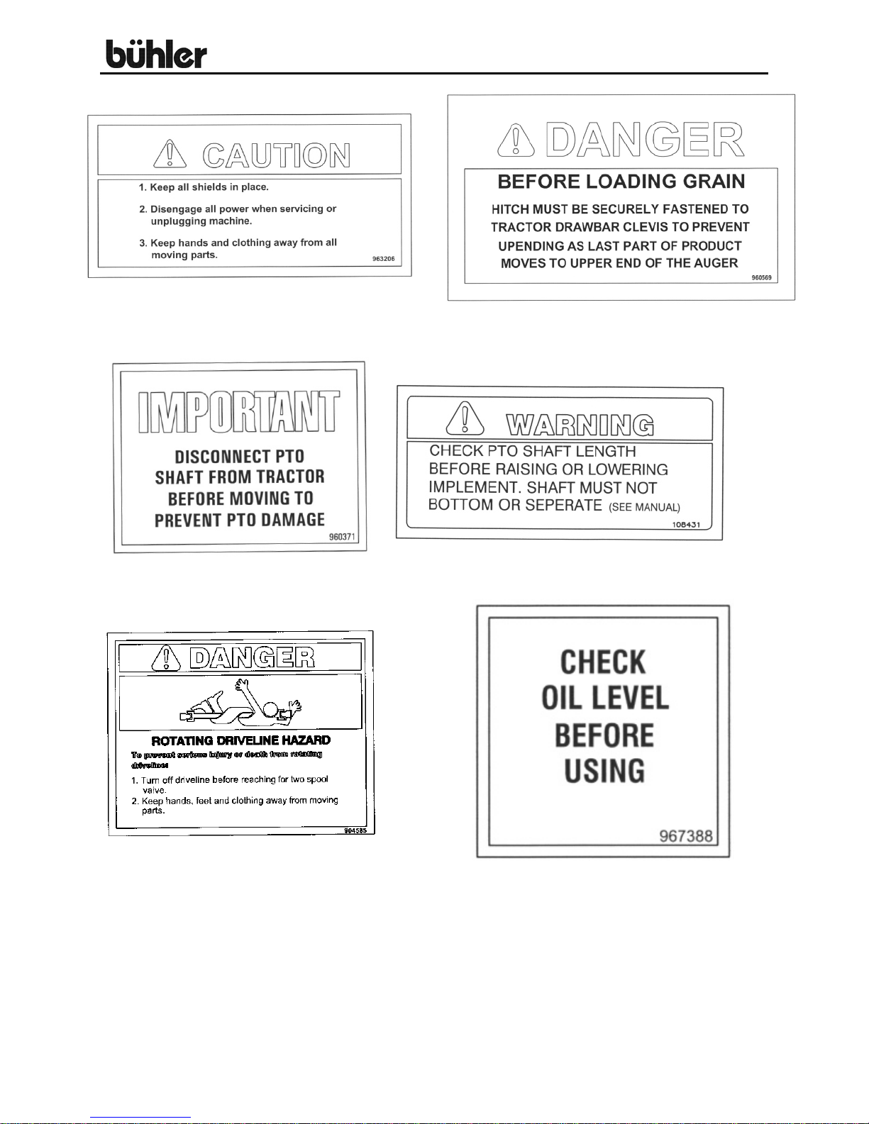
SAFETY SIGNS
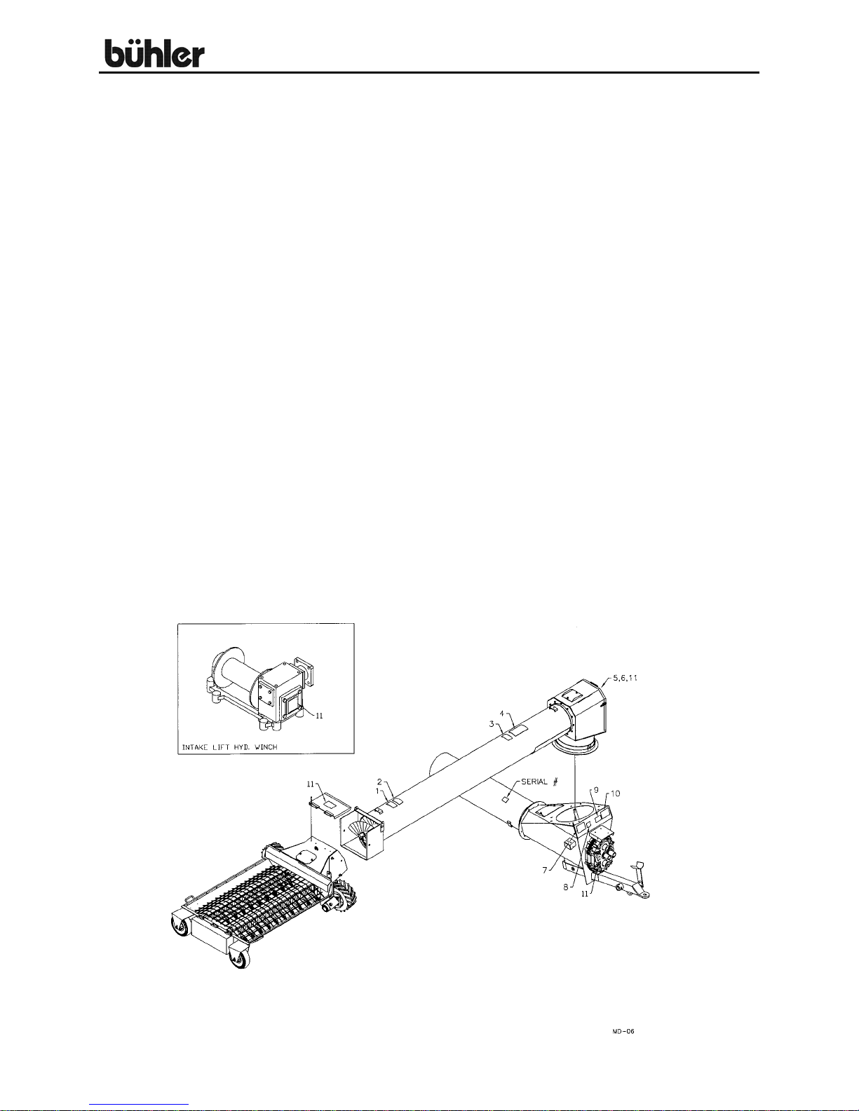
The following illustration shows the approximate location and detail of safety signs.
Keep all safety signs clean and legible and replace any that are damaged or missing.
When original parts are replaced, any safety signs affixed to those parts should be
replaced as well. Replacement safety signs are available from your local dealer.
INSTALLATION
To install safety signs, ensure the installation area is clean and dry. Decide on the exact
position before you remove the backing paper. Remove the smallest portion of the split
backing paper and align over the specified area. Carefully press in place. Slowly peel
back the remaining paper and smooth the remaining portion in place. Small air pockets
can be pierced with a pin and smoothed out.
16” AUGER SAFETY SIGNS
7
Page 11
16” Backsaver Auger
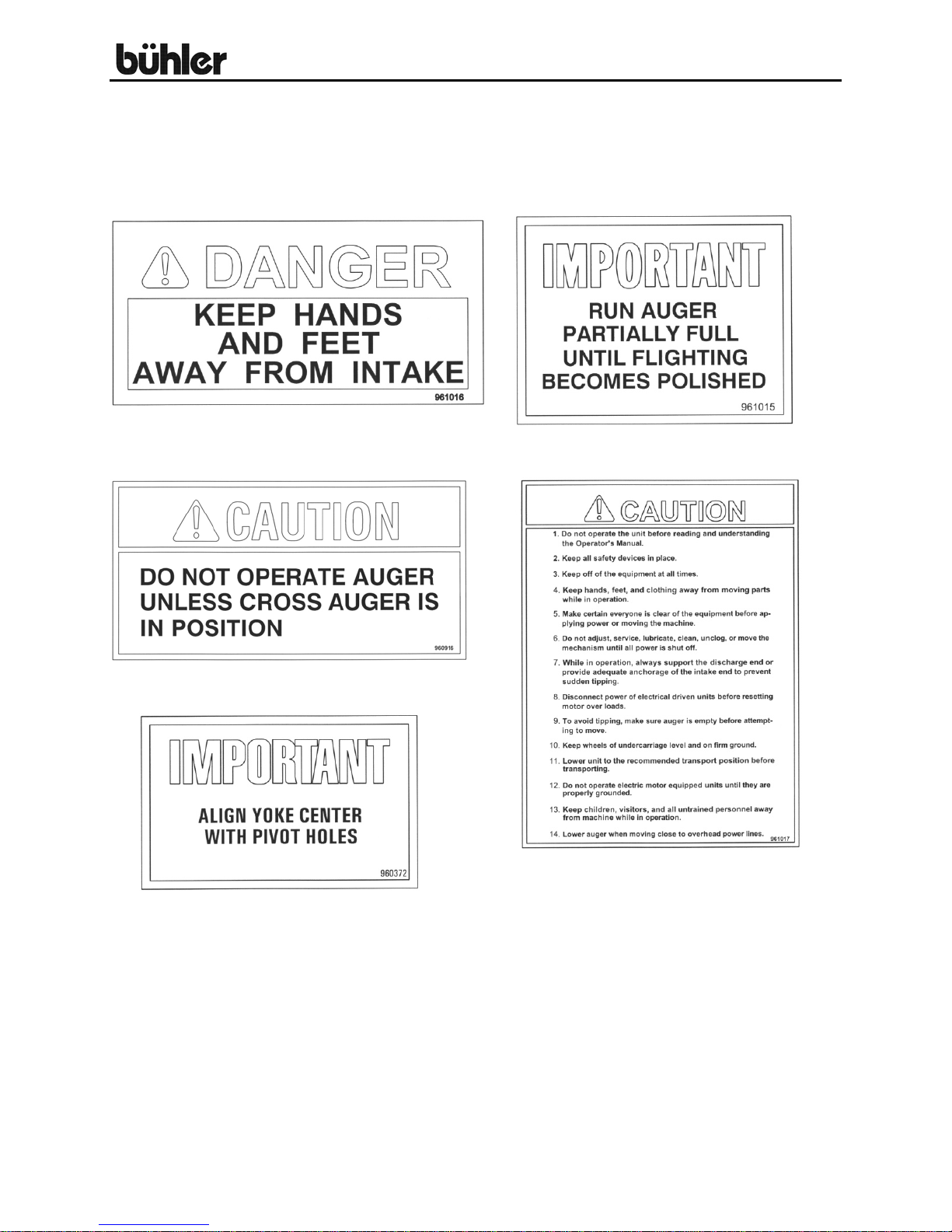
SAFETY SIGNS
Replace safety signs immediately should they become damaged, torn or illegible.
Obtain replacements from your authorized dealer using the part numbers shown.
#3
#1
#5 #4
8
Page 12
16” Backsaver Auger
#6
#7
#8 #9
#10
#11
9
Page 13

16” Backsaver Auger
ASSEMBLY INSTRUCTIONS
The assembly of this auger will require a 3-ton overhead crane and a forklift. Many of
the components are very heavy so they cannot be maneuvered into place without this
equipment.
1. Start the assembly by assembling the entire lift system (pages 32-34). With the
axle weldment (#7) turned as shown. Bolt on the stub axles (#58) using ¾” x
2 ¼” hex bolts, lock washers and hex nuts. Mount the wheel and the tire
assemblies (#48) using 5/8” x 2 ½” wheel bolts. Torque wheel bolts to 160 ft/lbs.
ALERT: Do not tighten any hardware for the rest of the lift assembly.
2. Mount the left hand undercarriage arm (#1) to the welded plate on the axle using
¾” x 2 ½” hex bolts, lock washers and hex nuts. Next attach the left hand lower
lift arm (#9) with a 1 ¼” x 7 1/8” pin (#11) and a ¼” x 1 ¾” cotter pin.
3. Assemble the two cylinders (#57), the two yokes (#13) and the link weldment
(#14). The yoke arm fits against the outside of the link and against the center
divider of the link. The cylinder ends fit in the open spaces left in the link. Join
parts using a 2” x 18 7/8” pin (#17) and a ¼” x 2 ½” cotter pin.
ALERT: Cylinder ports should be facing down.
4. Position the cylinder, link arm and yoke assembly up against the left hand lower
lift arm. Before attaching the right hand lower lift arm (#10) to the axle. At this
point you should lift up the ends of the cylinders until the assembly connecting
the lower lift arms is finished. With the cylinders raised, connect the two lower lift
arms with the torque tube weldment (#55) using ½” x 2” hex bolts, lock washers,
flat washers and hex nuts. Welded brackets on the torque tube must be turned
up
5. Bolt the cradle rest (#12) to the welded brackets on the torque tube using 5/8” x 3
½” hex bolts, lock washers and hex nuts. Connect the yoke, link and cylinder
assembly to the bottom of the lower lift using a 2 ¾” x 39” pin (#20). Fit the end
of the link between the bottom bushings on the lower lift arms. Insert the pin
through the right hand lift arm first, the link second and then the left hand arm.
Lock the ends of the pin in place with ½” x 3 ½” bolts and lock nuts.
6. Connect the upper lift arm (#8) to the upper bushings on the lower lift arms
using 2” x 9 5/8” pins (#21) and 5/16” x 3” cotter pins. These pins must be
installed with the head of the pin facing the center of the auger and the cotter pin
end facing out. Attach the ends of the yokes to the upper lift arm using a 2” x 20
½” pin (#15) and a ¼” x 2 ½” cotter pin.
10
Page 14

16” Backsaver Auger
ASSEMBLY INSTRUCTIONS – cont’d.
7. Attach the two cylinders to the welded bracket on the upper lift arm using a 2” x
17 ¼” pin (#16) and a ¼” x 2 ½” cotter pin. Attach the right hand undercarriage
arm (#2) at this point. Connect the two undercarriage arms with the tie plate (#5)
using 5/8” x 1 ¾” bolts, lock washers and hex nuts.
8. Lift the end of the lift arm assembly slightly above the undercarriage arms. Bolt
the lift arm rest tube (#6) to the top surface of the angle irons welded to the inside
of the undercarriage arms. Lower the lift arms onto the rest tube. The hardware
on the lift assembly will be tightened after the assembly is connected to the
tubing and is positioned in place.
9. After the lift assembly is complete, the main tubing is assembled (pages 27-31).
Align tubes and assemble tube number 5 (#5) to the top of number 4 (#4) using
5/8” x 1 ¾” grade 8 hex bolts, 5/8” S.A.E. flat washers and lock nuts. Two side
bridging brackets (#18) are bolted to the sides of each pipe ring connection at the
same time that the pipe rings are bolted together. Align the flighting with the
couplers at the ends and bolt together using a ¾” x 4” bolt and lock nut. Next,
assemble tube number 3 (#3) to tube number 2 (#2). Finally, bolt tube number 1
(#1) to tube number 2.
10. Pages 35-39. Couple the 12 7/8” drive shaft (page 35, #11) to the bottom end of
the flighting using a ¾” x 4” hex bolt and lock nut. Make sure the shaft fits into
the RPM gearbox (#26) before bolting to the flighting. Insert a 3/8” x 7 3/8” key
(#12) into the drive shaft and slide the input box assembly (#1) onto the drive
shaft. Line up the flange bolt holes on the input box with the pipe ring and bolt
together using 5/8” x 1 ¾” grade 8 hex bolts, S.A.E. flat washers and lock nuts.
The drive shaft is held on by inserting a 5/8” x 1 ¾” bolt, lock washer and a ½”
thick x 3” flat washer (#24) at the end of the shaft. Insert splined drive shaft (#84)
into the outer coupler on the gearbox and attach PTO shaft (#85).
ALERT: There are two holes on the top stub shaft for cotter pin installation on
the top flighting which should allow for a wide range of adjustment.
11. Pages 27-31. Attach all the bridging yokes. The main bridging yoke (#11) bolts
to the welded brackets on tube numbers using 5/8” x 1 ¾” hex bolts, lock
washers, flat washers and hex nuts. Attach the two braces (#12) to the main
yoke using ½” x 1 ½” hex bolt, lock washers and hex nuts. Tube number 1 has a
74” long yoke (#9) with a 34” brace (#10) bolted on using the same hardware.
Tube number 3 uses a 103” long yoke (#13) with a 43” brace (#14) also with the
same hardware. The final bridging yoke bolts to tube number 4 which is a 60”
long yoke (#16) with a 27 ¾” brace (#17) also using the same hardware.
11
Page 15

16” Backsaver Auger
ASSEMBLY INSTRUCTIONS – cont’d.
12. Pages 27-31. Using an overhead hoist, put a sling around tube number 1 and lift
so the bottom end is raised about 12 inches. Attach the shorter top bridging
cable first (#78). This cable goes from just below the undercarriage pivot plate
on tube number one, across the main bridging yoke and to the top end of tube
number 3. Bolt the 2” wide cable yokes (#83) to the top end of each cable using
¾” x 2 ½” hex bolts, lock washers and hex nuts. Bolt the yokes to the cable
brackets welded to tube number 3 with the same hardware. Use the bottom hole
in the yoke if possible. The other holes can be used if the cable stretches after a
few years. The long top bridging cable (#79) goes from the lower part of tube
number 1, across the main bridging yoke and to the center of tube number 5.
Use the same hardware as the short cables. The side bridging cables (#77) run
across the four side bridging brackets on each side of the pipe rings from tube
number 1 to tube number 5. Use the 1 ½” wide cable yokes (#84) at the top end
of these cables. The hardware for these cables is ½” x 1 ¾” hex bolts, lock
washers and hex nuts. The top bridging cables are tightened using the threaded
rods at the bottom end until the tubes bow up a few inches. Tension the side
cable evenly so tubes are straight left and right. Tighten cable clamps after
tensioning is complete.
ALERT: On yokes where the cable clamps hold two cables, do not use the cast
part of the cable clamp.
13. Put a sling around the tubing at a point just above the main bridging yoke. Raise
the top end of the tube assembly high enough to fit the discharge spout
(page 28, #82) over the spout opening. Bolt on spout using 3/8” x 1” hex bolts,
lock washers and hex huts.
14. Tension the flighting using the crown nut at the top of the flighting. Snug up this
nut and then give it about an extra 1/4 turn. Do not over tighten. You only want
the weight of the flighting to hang from the top bearing.
15. Pages 32-34. Bolt the undercarriage connector plates (#41) to the welded
brackets on the sides of tube number 1. Use 5/8” x 1 ¾” hex bolts, lock washer
and hex nuts on the top 2 holes. Flat head bolts on the bottom 2 bolts. Lift the
tube assembly high enough to roll the lift assembly underneath centered on the
tubing. You will need an overhead crane with a 3 ton capacity to lift the tube
assembly. The holes at the end of the undercarriage arms must line up with the
holes in the connector plates. Slide a 3” o.d. x 24 ½” long tube (#3) through all
four holes and lock in place with 1 ½” wide collars (#4), ½” x 4 ½” hex bolts, lock
washers and hex nuts. Connect the upper lift arm to the bottom of the main
bridging yoke using a 2” x 22 ½” pin (#18). Lock in place with collars (#19),
½” x 3 ¼” hex bolts, lock washers and hex nuts.
12
Page 16
16” Backsaver Auger
ASSEMBLY INSTRUCTIONS – cont’d.
16. Lift up the tubing assembly so lift assembly is a few inches above the cradles.
Center the upper lift arm on the cradle. This will require a forklift. Tighten all lift
arm and undercarriage hardware while the tube assembly is raised. Lower back
into cradle when hardware has all been tightened.
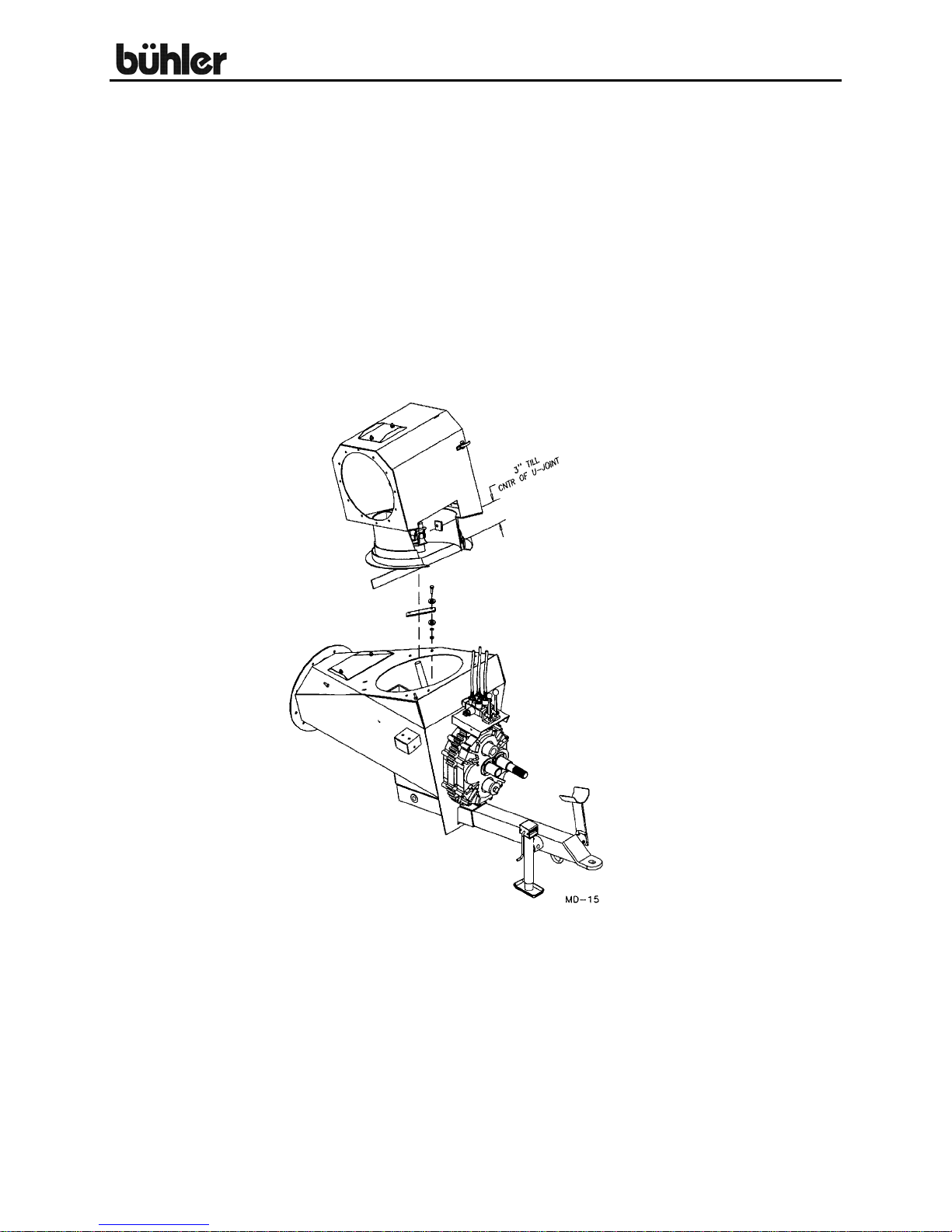
17. Using 3/8” x ¾” sq. hd. set screws and a 3/8” x 1 ½” key mount the u-joint
(page 35, #98) on the intake auger gearbox. Position the u-joint by placing a
straight edge along the bottom of the pipe ring on the intake auger top box
(page 35, #67) and measuring exactly 2 ½” from the top of the straight edge to
the center of the u-joint as shown in drawing.
18. Pages 35-39. Lift the intake auger assembly onto the input box (#1). The
splines on the U-joint must slide onto the splines on the input box gearbox. This
will require a hoist. Let the ring sit on the input box without forcing it to the exact
center if it is not positioned perfectly. Flip open the intake auger top door (#77)
and bolt on the ring using 3/8” x 1 ½” hex bolts. A 3/8” (10 gauge) flat washer
goes under the input box top cover. The 1 ¼” o.d. flat washers should be 1/8” to
3/16” from touching the edge of the ring. This is done to prevent side pressure
on the u-joint. Four 2” x 6 ½” plates (#33) act as a ring holder. Tighten bolts
using 3/8” lock washers and hex nuts. The intake auger should turn freely
around the input box.
13
Page 17

16” Backsaver Auger
ASSEMBLY INSTRUCTIONS – cont’d.
ALERT: If the intake auger is removed for repair or replacement, the bolt
coupling the flighting to the intake auger gearbox must be replaced when the
flighting is replaced. Not replacing this bolt could cause failure of the hopper
flighting.
19. Using a 3/8” x 1 ½” key and 3/8” x ¾” sq. hd. set screws, join the hopper flighting
and the intake auger flighting at the universal joint (page 36, #48). Join the
hopper and intake auger using two ¾” x 1 5/8” bolts and lock nuts. A flat washer
goes on the outside only. Parts must swivel freely after bolting together. Check
that the cross on the u-joint is in line with the two pivot bolts.
The cover (page 36, #63) bolts to the front edge of the hopper using ¼” x ¾” hex
bolts, lock washers and hex nuts. The cover is held down by the cover rod
(page 35, #64) which is pushed through the clevises welded to the intake auger
and held in place with a 3/16” x 1 ½” cotter pin. Check that all the set screws on
the u-joint have been tightened and that the u-joint has grease before closing the
cover.
ALERT: Never run the auger without this cover bolted on. The yoke center must
align with the pivot holes after assembly.
20. Pages 36-39. Bolt the 7” wide rubber edging (#59) supplied to the top edge of
the hopper using ¼” x 1” hex bolts, lock washers and hex nuts. Use 1” wide
strips on the sides of the hopper (#90) and on the outside edge (#88). These
strips fit on the inside of the hopper and help keep the rubber from tearing. The
ends of the rubber strips are joined using connector plates (#91) with ¼” x 1” hex
bolts, flat washers, lock washers and hex nuts.
21. The lift boom (page 22, #20) is bolted to a welded bracket on top of tube number
1 about 136” from the bottom pipe ring using 5/8” x 1 ¼” hex bolts, lock washers
and hex nuts. The intake auger lift cable (page 22, #85) has a safety hook at one
end. Thread the other end of the 3/8” cable around the pulley at the end of the
lift boom and then around a cable pulley in the bracket which swivels at the back
of the lift boom. Bolt the hydraulic winch (page 22, #89) and solenoid assembly
to the welded winch bracket near the bottom of tube number 1 using ½” x 2” hex
bolts, flat washers, lock washers and hex nuts. NOTE: The end of the lift cable
must be run through the winch guard (page 22, #93) before attaching the cable to
the winch. Bolt on the winch guard using ½” x 1 ½” hex bolts, lock washers and
hex nuts. There are flat irons with two holes welded near the front on the sides
of the hopper. Hook the lift cable in the upper hole on the far side of the hopper
so the hopper will turn open end toward the auger. This is the standard transport
position. The safety chain is attached to the loop at the top end of the hopper.
This chain should always be attached when transporting the auger. The lift boom
can be used on either side of the auger. The lower hole on the hopper bracket is
used for clean out only.
14
Page 18

16” Backsaver Auger
ASSEMBLY INSTRUCTIONS – cont’d.
ALERT: When the intake auger is raised from working position, the lift cable is
hooked into the loop at the top of the hopper. The open end of the hook must be
turned toward the hopper. The intake auger could detach and fall if the main
auger is raised with the hook turned the other way.
22. Pages 40 & 41. The hydraulic line on the auger must be coupled at the pipe
rings between tube number 1 and tube number 2 using a 63” hydraulic hose
(#21). Screw a 90 degree elbow (#25) into the ball valve (#26) and connect this
assembly to the bottom of the hydraulic line. Attach a 120” hydraulic hose (#24)
to this elbow. The other end of the hose connects to the tractor.
23. Connect the 8’-6” hydraulic hose (page 40, #15) with the assembled 12” lines
and fittings from the base of the cylinders to the hydraulic line on the main auger.
All fittings should be taken apart and sealed with Teflon tape before tightening.
Install the two vent plugs (page 32, #42) in the cylinders.
ALERT: The flow control valve (page 40, #16) regulates the lowering of the
auger to avoid damage which could be caused by lowering the auger too quickly.
Arrow on the flow control should be pointing toward the 6 foot hose. Be sure that
the valve is open approximately 3 ½ turns before raising the auger to full height
or the auger will not lower.
24. Pages 40 & 41. Assemble the fittings into the two spool valve assembly (#1).
There are two #12 MORB to #8 MJIC adaptors (#7) in the side ports. With the
valve turned as shown on page 31, fit two #10 MORB to #8 MJIC adaptors (#8)
in the right hand ports on top of the valve. The left hand ports which control the
mover use adaptors with a restrictor valve (#28).
25. Pages 40 & 41. Assemble the fittings into the hydraulic motors (#10). The upper
port on the motor uses a #12 MORB straight adaptor (#7) while the lower port
uses a 90 degree #12 MORB adaptor (#6). The two straight adaptors are joined
using a 79” hose (#3). Two 21 foot hoses (#2) attach to the 90 degree elbows on
the hydraulic motor. They run up between the motor and the hopper and along
the intake auger tube till the right side ports, on top of the valve (as shown).
These lines are clamped down to the top of the intake auger tube using hose
holders (page 35, #31) with 3/8” x 1” hex bolts, lock washers and hex nuts. The
hopper mover is controlled by the valve handle which lines up with the two ports
the hoses are attached to in the valve.
ALERT: The hopper mover may move quite quickly with some tractors. Be sure
everyone is clear of the area when using the mover.
15
Page 19

16” Backsaver Auger
ASSEMBLY INSTRUCTIONS – cont’d.
26. Pages 40 & 41. Attach the 139” hydraulic hoses (#5) to the relief valve (#12)
bolted to the winch hydraulic motor. These hoses run down the tube, alongside
the input box and connect to the left side ports on the top of the valve. The winch
has a pressure relief valve so the hoses must be connected to the correct ports.
Check hydraulic system drawing to verify. Two 79” hoses (#4) connect to the
sides of the valve. These both attach to the tractor.
27. The relief valve (page 40, #12) bolted to the winch hydraulic motor should be
adjusted before using. The power is adjusted on the control screw at the top of
the unit. Loosen the hex nut on the threaded shaft and adjust using an Allen
wrench. Adjust so you have enough power to lift the empty intake auger off the
ground. Lock the setting in place with the hex nut. The winch speed is adjusted
by a control screw on the side. Remove the plug and adjust the speed with an
Allen wrench. Adjust so the intake auger lifts slowly and replace the plug.
28. The standard drive position for the drive shaft (page 35, #85) in the rpm gearbox
(page 35, #26) is in the outer coupler. The center coupler on the gearbox is used
to reverse the flighting. This should be used to clean out the auger only. There
are two solid plugs in the side of the gearbox. The higher of the two plugs should
be removed and replaced with a 90 degree vent plug (page 50, #17). The lower
of the two plugs acts as an oil level plug.
29. Re-check and tighten all bolts.
30. Immediately after setting up the auger, hook it up to a tractor. Raise and lower
the auger three or four times to purge all the air out of the hydraulic line to the lift
cylinder. This will help to prevent the auger from settling when you have it in
working position above a bin.
ALERT: Always check to see that both ends of the PTO shaft are securely
attached every time the auger is used. This should always be done with the
tractor engine shut off. When transporting the auger, disconnect the PTO shaft
from the tractor. The PTO holder at the end of the hitch is used to hold the PTO
during transport.
Do not run the auger with the intake auger in the transport position. Doing this
will damage the u-joint between the intake auger and the input box.
16
Page 20

16” Backsaver Auger
LIGHT KIT ASSEMBLY
The light kit can be assembled while assembling the auger or it can be added
afterwards. The light kit will have to be used in conjunction with the reflective safety
decals in some areas. Check local laws to see if this applies in your area. The
reflectors and instructions for their placement are in the crate of parts. Always use the
light kit when moving the auger on a public roadway.
1. Pages 42 & 43. The main harness (#1) along with the two lines to the halogen
lamps (#2 & #3) connect to the two switches (#9) mounted in the switch box
welded to the input box. Use a clip (#16) and a 5/16” x ¾” hex bolts, lock washer
and hex nut to fasten the main harness to the side of the valve mount on the
input box. The main harness has a 7 pin round end. An adapter (#10) which
coverts 7 pin round to 7 pin flat is supplied with the light kit. See the wiring
schematic for the proper wiring. Hook-up at the switch.
2. Bolt one halogen lamp (#8) to the top box on the intake auger as shown in
drawing. Position the lamp so it points at the hopper. Halogen lamps are for
use during auger operation only. Switch them off during transport. The harness
for the intake auger lamp is clamped on with clip (#15) using the top bolt on the
clean out at the top of the intake auger. The other end of the harness connects
to the switch as shown in wiring schematic.
3. Bolt the second halogen lamp (#8) to the top end plate on the auger. Bolt cable
brackets (#11) to all four sets of pipe rings using the top two bolts on the pipe
ring as shown in drawing. Run the 107-foot wiring harness (#3) from the halogen
lamp at the top down to the switch. Clamp the harness to the cable brackets on
the pipe rings using clips (#15) with 5/16” x ¾” hex bolts, lock washers and hex
nuts. Pull the bottom end of the harness through the cable brackets and lower
bridging stand welded to the bottom auger tube. Connect the bottom end of the
harness to the switch as shown in the wiring schematic. A clip (#15) holds the
harness at the top of the auger using one of the bolts holding on the top end
plate as shown in drawing. Use this lamp for positioning the spout over a bin.
4. The three lines running to the switch box must be fitted through three straw relief
connectors (#20) mounted in the switch box bottom plate (#14). Assemble the
connectors with accompanying lock nuts (#21) on the three wires before making
the final connections. Bolt the bottom plate to the switch box using 5/16” x ¾”
hex bolts and lock washers. Lock the wires in place using the lock nuts which fit
onto the connectors.
17
Page 21

16” Backsaver Auger
LIGHT KIT ASSEMBLY – cont’d.
5. Remove the nuts and lock washers from the top two bolts on both
undercarriage clamp plates and bolt on the right and left blinker mount
weldments (#12 & #13). The ends should face out across the tire. Bolt an
amber light (#7) to the top of each mount. The 30-inch harness (#6) connects
to the light on the right hand side as shown in drawing. The two lights are
joined by a 13-foot harness (#5). Use nylon ties to fasten the harness to the
axle so it will not hang down. The 45 foot harness (#4) attaches at the point
where the 30 inch and 13 foot cables join. Run this wire along the right hand
undercarriage and clamp on using nylon ties. Thread the remaining wire
through the openings in the cable brackets welded to the side of the auger
tube down to the switch box. Connect the end to the main wiring harness
6. Connect the main wiring harness to the towing vehicle and check to see that
all lights are working properly. The halogen lamps should turn on and off with
the switches. The amber lights should turn on and off with the towing vehicle
lights. Use the vehicle flasher if you want the amber lights to flash.
18
Page 22

16” Backsaver Auger
OPERATING INSTRUCTIONS
All augers may be elevated up to 45°; however, for the best operating efficiency 35°
should not be exceeded. At angles over 35° the capacity and life of the auger
decreases. Use in some types of fertilizer may cause accelerated wear and corrosion
as well as added stress on lift components due to additional load. Use in fertilizer can
affect warranty.
Run auger partially full until flighting becomes polished.
Never operate an empty auger for over one minute as the flighting and housing will
experience excessive wear.
To position the auger, always tow or move the auger in the down position to a point as
close as possible to the bin or barn.
ALERT: Always keep the wheels level. Raise the auger to the desired height
and back the auger into position. Do not support the auger on the bin. As the auger
becomes full it carries a lot of weight and may cause damage to the underside of the
auger or to the bin. The auger should be firmly attached to the drawbar of the tractor at
all times during operation.
ALERT: Never place blocks under the wheels to increase the elevation of the
auger.
Be sure the wheels are free to move and no one is standing close to the auger when
raising or lowering. Never attempt to raise or lower the auger while it is in operation.
The intake auger swivels freely on the top of the input box. It can be positioned
anywhere between the tractor and the side of the auger.
ALERT: 16" Augers are designed for PTO drive tractors with 1000 rpm only.
Maximum capacity will be attained while running the main auger at or near 1000 rpm.
NOTE: The weight of the intake auger and hopper assembly must be supported by the
transport chain, whenever the auger is moved. If the weight of the intake auger is on
the winch, the winch may be damaged during transport.
The auger uses a hydraulic winch to lift the intake auger. Never have less than three
wraps of cable on the drum of the winch.
ALERT: Never operate the hydraulic winch or the hopper mover when the PTO
shaft is engaged.
A two-spool valve assembly on the back of the input box controls both the hopper
mover and the hydraulic winch. See drawing for proper hose plumbing.
19
Page 23

16” Backsaver Auger
OPERATING INSTRUCTIONS - CONT'D.
ALERT: Always maintain at least a 4” overlap on the PTO shields. Be sure
they turn freely and make certain everyone stands clear of the tractor, PTO shaft, and
auger before engaging power take-off. Be sure ends are securely connected to the
auger and tractor.
The distance between the tractor and the auger stubs should be between 40” and 42”
with the tractor and auger on level ground and the auger in full down position. This
distance is obtained by either adjusting the tractor hitch, the auger hitch or both.
Before engaging power take-off, start tractor and idle engine. Engage power take-off
slowly and bring PTO rpm up to recommended speed of 1000 rpm for 16" augers.
Before stopping auger (except in an emergency) let all grain empty out of the auger, idle
engine then disengage power take-off. Shut off tractor.
ALERT: Do not use the reverse kit to attempt to unplug the auger. The reverse
kit is designed to be used for CLEAN-OUT ONLY!
ALERT: When auger is left in raised position over night, close the ball valve on
the hydraulic line to the cylinder. This will prevent the auger from lowering, due to
hydraulic leakage, and avoid possible damage.
The hydraulic winch is designed to lift an empty intake auger only. Clean out hopper
before attempting to lift with the winch. Do not lift the main auger any higher than 35
degrees before lowering the intake auger. There will be interference between the intake
auger and the input box if you go any higher.
20
Page 24

16” Backsaver Auger
OPERATING INSTRUCTIONS - CONT'D.
One-way flow control valve can be adjusted by loosening the hex nut on the side, and
turning on the screw with the machined end. Turning the screw in decreases the speed
the auger lowers, while turning it out increases the speed. The approximate initial
setting should be 3 ½ turns out from the tight position. When set, re-tighten hex nut to
set position. NOTE: Be sure that the valve is somewhat open before raising the first
time or auger will not lower.
Be sure there is always some tension on the flighting by adjusting the end thrust bearing
at the upper end of the auger.
ALERT: Always lower auger before transporting and allow the weight of the
auger to rest on the undercarriage and not the hydraulic cylinder.
Be certain to turn jack sideways when towing auger.
ALERT: Disconnect the PTO shaft from the tractor and pin it in place in the PTO
holder when towing or maneuvering the auger. This will prevent possible damage to the
PTO shaft during cornering.
ALERT: If the PTO shaft angle exceeds 50° during a tight turn, the constant
velocity joints will be fractured and will likely fail shortly thereafter during operation.
PTO shear bolts (2 required) – 3/8" x 1" hex bolt (grade 8)
ALERT: When towing the auger, never exceed 32 kilometers per hour.
This 16” auger has a total weight of about 13,000 pounds and a hitch weight of about
2,700 pounds. You must have a vehicle rated for this amount of weight to transport this
auger.
21
Page 25

16” Backsaver Auger
THEORY OF OPERATION
22
Page 26

16” Backsaver Auger
MAINTENANCE & LUBRICATION
Check condition of winch cable regularly. Be sure it is lubricated. Replace cable if you
notice any broken strands.
Check to see that there is no downward bow in the main tubes at the start of every
augering season. Re-tension cables if required as per the assembly instructions. This
should also be checked immediately after hauling the auger for a long distance.
Use a high temperature grease for all lubrication.
Lubricate the PTO shaft as per instruction sheet.
Check grease on end thrust bearing to be sure it is running smoothly and freely.
Remove cap and grease at the start of every season.
Check hydraulic lines frequently for leaks or damage.
Grease universal joint in intake auger after every eight hours of use.
Grease the U-joint connecting the two gearboxes about every 8 hours. Do regular
checks on the oil level in the gearboxes. Fill if necessary to the height of the side plug
using SAE 90 oil. Because the gearbox runs in the grain, it is difficult to see any oil
leaks so regular checks should be done. The reducer gearbox requires 2.5 litres of
75W–90 synthetic oil. Reducer gearbox should be serviced every year or every 1000
hours. The hydraulic winch gearbox requires 2.5 litres of 80w-90 gear oil.
ALERT: When replacing bearings or tightening a loose bearing collar, always
tighten collar in the
Recommended tire pressure is 45 to 50 psi (max. 60 psi).
direction of shaft rotation using a center punch or a similar tool.
23
Page 27

16” Backsaver Auger
STORAGE
The auger should be stored in a dry place if possible. If stored outside, lower auger to
its lowest position and block up the wheels so auger will not move.
Clean auger thoroughly as dirt draws moisture and causes metal to rust. If the auger
has been used to move fertilizer, clean thoroughly and apply oil or grease on entire
flighting and inside the housing to stop and prevent further corrosion.
At this time check all moving parts for wear and order replacement parts from your
nearest dealer.
When taking the auger out of storage, clean it thoroughly and check for obstructions at
the inlet and outlet ends.
Check all bolts and set screws.
Regularly check the tightness of all cable clamps to avoid slipping. Inspect wire rope
regularly for evidence of wear or corrosion. Such inspections should take place at
progressively shorter intervals over the useful life of the rope, as wear tends to
accelerate with use and/or age. Where wear is rapid, the outside of a wire rope will
show flattened surfaces in a short time. A piece of cloth or rag, rubbed along the wire
tope will help to reveal broken wires. The effects of corrosion are not easy to detect
because the exterior wires may appear to be only slightly rusty, and the damaging
effects of corrosion may be confined to the hidden inner wires where it cannot be seen.
To prevent damage by corrosion, the rope should be kept well lubricated. Periodic
cleaning of wire rope by using a stiff brush and kerosene or with compressed air or live
steam and relubricating will help to lengthen rope life and reduce abrasion and wear on
sheaves and drums.
24
Page 28

16” Backsaver Auger
RECOMMENDED CUSTOMER GREASING PROCEDURE FOR
50 DEGREE DOUBLE C.V. PTO
A general purpose grease may be used. However, a grease containing 3%
molybdenum disulfide will allow the lube intervals to be extended to twice as long as
that listed. The first lube interval should be 16 – 24 hours of operation after initial startup; then follow the schedule below. Constant angle applications must have a lube
interval of 4 hours.
LUBE RECOMMENDATIONS
INTERVAL LOCATION AMOUNT
8 hrs. Cross & Bearings 1 pump
8 hrs. Telescoping Members 4-8 pumps (until grease comes out of end)
8 hrs. CV Ball & Socket 1-2 pumps
Greases containing various percentages of moly. are available as extreme pressure
greases. Please note that not all E.P. greases contain moly so some investigation may
be necessary. The following greases all contain 3% moly: Mobile Oil Company,
“Mobile Grease CMP”; Shell Oil Company, “Retinax AM”; and Texaco, “Molytex EP (#0)
and (#2)”.
25
Page 29

16” Backsaver Auger
MAINTENANCE
26
Page 30

16” Backsaver Auger
TUBE ASSEMBLY
27
Page 31

16” Backsaver Auger
TUBE ASSEMBLY
28
Page 32

16” Backsaver Auger
WHEN ORDERING PARTS
Always give your dealer the Model, Color and Serial Number of your machine to assist
him in ordering and obtaining the correct parts. Use the exploded view and tabular
listing of the area of interest to exactly identify the required part.
TUBE ASSEMBLY
Item # Part # Description
1 909704 Tube Weldment #1
2 909705 Tube Weldment #2
3 909706 Tube Weldment #3
4 909707 Tube Weldment #4
5 909708 Tube Weldment #5
6 905760 Flighting Weldment Tube #1
7 905763 Flighting Weldment Tube #2, 3, & 4
8 905766 Flighting Weldment Tube #5
9 905816 Bridging Plate 3" x 74" (Tube #1)
10 905817 Bridging Brace 2" x 34"
11 905826 Bridging Plate 1/2" x 5" x 84 1/2"
12 905827 Bridging Brace 1 5/16" OD x 63"
13 905828 Bridging Plate 3" x 103" Lg (Tube #3)
14 905829 Bridging Brace 2" x 43"
15 905830 Bridging Brace 2" x 31 5/8"
16 905831 Bridging Plate 3" x 60" (Tube #4)
17 905832 Bridging Brace 2" x 27 3/4"
18 906076 Side Bridging Bracket 15 7/16" x 24 7/8"
19 905811 Side Plate Weldment
20 905815 Arm Tube Weldment 3" Sp. X 45" Lg
21 905819 Pulley Holder Weldment
22 905821 Pin Weldment 3/4" x 4 1/4" Lg
23 905823 Pin Weldment 1" x 6 1/2"
24 961846 Cable Pulley 3 1/2" OD x 1 1/8" W
25 960913 1/2" x 1 13/16" Clevis Pin (pl)
26 9812430 1/8" x 1" Cotter Pin (pl)
27 961012 Hair Pin Clip #16
28 967233 1" x 10" Hex Bolt (pl)
29 84051 1" Jam Nut (pl)
30 9812433 3/16" x 1 1/2" Cotter Pin (pl)
31 909172 Quick Link 3/8'' (pl)
32 909171 Hook w/ Latch (3/4 Ton)
33 906101 Top Plate Weldment 16 3/8" OD
34 907052 Oil Seal (CR17617)
35 965252 Inner Bearing Cup (25520)
29
Page 33

16” Backsaver Auger
36 967205 Outer Bearing Cone (25580)
37 905906 End Bearing Sleeve
38 9812445 Washer Narrow Rim 1/5 x 10 Ga (br)
39 907053 1 1/2" Slotted Hex Nut (br)
40 907312 Dust Cap
41 812435 1/4" x 1 3/4" Cotter Pin
42 81549 5/16" x 3/4" Hex Bolt (pl)
43 81569 5/16" Lock Washer (pl)
44 81568 5/16" Hex Nut (pl)
45 960140 Hydraulic Line Clamp 1" x 3 1/8"
46 86170 3/8" x 1" Hex Bolt (pl)
47 81593 3/8" Lock Washer (pl)
48 81592 3/8" Hex Nut (pl)
49 967463 1/2" x 120" Hydraulic Hose (Ends Solid &.5" NPT)
50 860585 1/2" x 90° Street Elbow (Stl.)
51 960057 1/2" Ball Valve
52 960152 Adaptor (JIC to 1/2" NPT)
53 960162 1/2" x 18" Hydraulic Hose (Both Ends JIC)
54 906104 Hydraulic Tube 5/8" x 230" Lg (MJIC Both Ends)
55 906105 Hydraulic Tube 5/8"OD x 205" Lg (MJIC Both Ends)
56 964565 1/2" Cable Clamp
57 909194 3/4" Cable Clamp
58 86171 3/8" x 1 1/4" Hex Bolt (pl)
59 81593 3/8" Lock Washer (pl)
60 81592 3/8" Hex Nut (pl)
61 967285 5/8'' x 1 3/4'' Hex Bolt (Gr.8)(pl)
62 812639 5/8'' SAE Flat Washer (pl)
63 84277 1/2" x 1 1/2" Hex Bolt (pl)
64 87553 1/2" x 1 3/4" Hex Bolt (pl)
65 81637 1/2" Lock Washer (pl)
66 81636 1/2" Hex Nut (pl)
67 811702 5/8" x 1 1/4" Hex Bolt (pl)
68 84268 5/8" x 1 1/2" Hex Bolt
69 84270 5/8" x 1 3/4" Hex Bolt (pl)
70 967287 3/4" x 4" Hex Bolt (pl)
71 81677 5/8" Lock Washer (pl)
72 81676 5/8" Hex Nut (pl)
73 81513 3/4" Lock Nut (pl)
74 84346 3/4" x 2 1/2" Hex Bolt (pl)
75 81701 3/4" Lock Washer (pl)
76 81700 3/4" Hex Nut (pl)
77 906045 Side Bridging Cable Assembled 79'
906044 Side Bridging Cable Only 80'-8"
30
Page 34

16” Backsaver Auger
78 906057 Upper Bridging Cable Assembled 48'
906056 Upper Bridging Cable Only 49'-8"
79 906059 Upper Bridging Cable Assembled 85'-4"
906058 Upper Bridging Cable Only 87'-0"
80 81972 7/8" SAE Flat Washer (pl)
81 81722 7/8" Hex Nut (pl)
82 906130 Discharge Spout
83 905853 Upper Cable Yoke Plate 2" x 10"
84 960244 Side Cable Yoke Plate 1 1/2" x 10"
85 906066 Winch Cable Assembly 3/8'' x 40'
86 116766 Hose 1/2" x 16'-6" 1/2'' MNPT x 3/4''MORB
87 971518 Hydraulic Motor 101-1018
88 909169 Release Valve
89 909143 Hydraulic Winch
90 905392 Elbow 3/4" MORB x 3/4" FORB
91 F0678 Flex Spout
92 812482 5/8'' Lock Nut (Stl.)(pl)
93 909201 Guard Winch 18'' x 30''
94 811791 1/2'' x 2'' Hex Bolt (pl)
95 81638 1/2'' Flat Washer (pl)
96 907642 Dust Cap Rubber Gasket (ctd#SE49)
97 812079 Adaptor Str. 3/4'' MORB x 1/2" SWFNPT
98 909783 Bridging Brace 2" x 51 3/4"
99 906043 Upper Bridging Tightener
100 960613 Side Bridging Tightener
101 967249 5/16" X 2" Socket Head Bolt (br)
31
Page 35

16” Backsaver Auger
LIFT ARM AND UNDERCARRIAGE
32
Page 36

16” Backsaver Auger
LIFT ARM & UNDERCARRIAGE ASSEMBLY
Item # Part # Description
1 905732 Undercarriage Weldment - L
2 905733 Undercarriage Weldment - R
3 905735 Undercarriage Pin 3" OD x 1/4" W x 24 1/2"
4 905736 Undercarriage Pin Sleeve 3 1/2" OD x 1.5" Lg
5 905737 Brace Plate 5" x 25 3/8"
6 905738 Lift Arm Rest Tube 3" Sq x 57 3/4"
7 905745 Axle Weldment 5" Sq x 141 1/2"
8 908445 Upper Lift Arm Weldment 188.44" Lg
9 F0612 Lower Lift Arm - L
10 F0611 Lower Lift Arm - R
11 905779 Axle Pin 1 1/4" Rd x 7 1/8" Lg
12 905786 Cradle Rest Weldment
13 908464 Yoke Arm Weldment
14 908472 Link Weldment
15 908480 Upper Lift Arm Pin 2" Rd x 20 1/2"
16 908478 Upper Cylinder Pin 2" Rd x 17 1/4" Lg
17 908490 Lift System Link Pin 2" Rd x 18 7/8"
18 905806 Upper Lift Arm Pin 2" Rd x 22 1/2" Lg
19 905807 Upper Lift Arm Pin Collar 2 5/8" OD x 1 1/2" Lg
20 908474 Connecting Link Pin 2 3/4" Rd x 39" Lg
21 908476 Lift Arm Clevis Pin 2" Rd x 9 5/8" Lg
22 81629 1/2" x 3 1/2" Hex Bolt (pl)
23 811691 1/2" x 4 1/2" Hex Bolt (pl)
24 81637 1/2" Lock Washer (pl)
25 81636 1/2" Hex Bolt (pl)
26 81669 5/8" x 3 1/2" Hex Bolt (pl)
27 84270 5/8" x 1 3/4" Hex Bolt (pl)
28 81677 5/8" Lock Washer (pl)
29 81676 5/8" Hex Nut (pl)
30 84346 3/4" x 2 1/2" Hex Bolt (pl)
31 81701 3/4" Lock Washer (pl)
32 81700 3/4" Hex Nut (pl)
33 812435 1/4" x 1 3/4" Cotter Pin
34 967162 5/16" x 3" Cotter Pin
35 116938 1/2'' X 8'-6'' Hydraulic Hose (1/2" NPT; JIC)
36 960118 Flow Control Valve
37 865341 Tee 7/8'' SWFJIC x 7/8'' MJIC
38 906103 Hydraulic Hose 1/2" x 12" (3/4" MORB;1/2" FNPT)
39 960152 Adaptor str. 7/8'' MJIC To 1/2'' Pipe MNPT
40 967162 5/16" x 3" Cotter Pin
41 904736 Undercarriage Connector Plate
33
Page 37

16” Backsaver Auger
42 967908 3/4 - 16 ORB Vent Plug
43 909184 Oil Seal
44 909185 Inner Bearing Cone
45 909188 Inner Bearing Cup
46 909186 Hub w/ Bearing Cups (8-Bolt)
47 909779 5/8" Wheel Nut NF (16")
48 909182 Wheel 14" x 16.1" x 8
49 909189 Outer Bearing Cup
50 909187 Outer Bearing Cone
51 9812442 1 1/4" x 10 Ga Narrow Rim Washer (br)
52 960037 1 1/4" Slotted Hex Nut Gr. 2 (br)
53 81207 3/16" x 2" Cotter Pin
54 909192 Dust Cap CTD #DC27
55 907741 Torque Tube Weldment 6" Od x 53" Lg
56 811791 1/2'' x 2'' Hex Bolt (pl)
57 F0664 Cylinder 5.00 x 55.35 W/ 3 1/2'' Shaft
58 906109 Bolt On Stub Axle Weldment (8-Bolt)
59 967900 1/4'' Grease Fitting
60 967284 5/8'' x 1 3/4'' Fl Hd Skt Bolt (pl)
61 81638 1/2'' Flat Washer Std. (pl)
62 967153 2'' x 10ga Narrow Rim Washer (pl)
63 909839 Wheel Stud 5/8" NF
909181 Tire - 16.5L - 16.1Fi
F0679 Wheel & Tire Assembly
34
Page 38

16” Backsaver Auger
INTAKE SYSTEM ASSEMBLY
35
Page 39

16” Backsaver Auger
INTAKE SYSTEM ASSEMBLY
36
Page 40

16” Backsaver Auger
INTAKE SYSTEM ASSEMBLY
Item # Part # Description
1 909641 Input Box Weldment
2 960483 Intake Auger & Input Box Clean Out Lid
3 9108493 Pto Holder Pin 5/8" x 7 7/8"
4 905879 Pto Hold Weldment
5 905887 Hitch Weldment
6 967527 1" x 5" Hex Bolt (pl)
7 904557 1/2" x 8 1/2" Hex Bolt (pl)
8 909837 Gearbox Mount Plate 7" x 18 1/2"
9 909983 Valve Assembly - Two Spool
10 967148 1" Lock Nut (pl)
11 905900 Drive Shaft 2" x 12 7/8" Lg
12 906061 Drive Key 3/8" Sq x 7 3/8" Lg
13 81581 3/8" x 2 1/2" Hex Bolt (pl)
15 81593 3/8" Lock Washer (pl)
16 91592 3/8" Hex Nut (pl)
17 97553 1/2" x 1 3/4" Hex Bolt (pl)
18 81637 1/2" Lock Washer (pl)
19 81636 1/2" Hex Nut (pl)
21 84498 1/4" Lock Washer (pl)
22 81544 1/4" Hex Nut (pl)
23 812365 3/4" Lock Nut (pl)
24 906073 Washer 1/2" x 3" x 21 /32" ID
25 905882 Input Box Gearbox
26 909827 RPM Box
27 909195 Jack
30 12779 #9 Hair Pin Clip
31 964638 Hose Holder 1" x 4 1/4"
32 81620 1/2" x 1 1/4" Hex Bolt
33 960653 Box Ring Clamp 2" x 6 1/2"
34 86170 3/8" x 1" Hex Bolt (pl)
35 905973 Hopper Weldment
36 905980 Outer Flighting Weldment
37 906063 Center Drive Shaft 1 1/2" x 59 7/8" Lg
38 905988 Center Flighting Shaft Weldment
39 906003 Rear Center Flighting Holder Assembly
40 906007 Outer Flighting Holder Assembly
41 960705 Key 3/8" Sq x 1 3/4" Lg
42 906021 Key 3/8" Sq x 2 5/8" Lg
43 968627 Bearing 1 1/2" w/ Collar
44 967260 Bearing Flange (80MM-SQ)
45 960719 Sprocket 15T 1 1/2" Bore #80
46 988999 3/8" x 3/8" Setscrew Scktser (br)
37
Page 41

16” Backsaver Auger
47 9812378 3/8" x 3/4" Setscrew Sqhead (br)
48 907282 U-Joint 1 1/2" Both Ends W/ 3/8" Keyway
49 84277 1/2" x 1 1/2" Hex Bolt (pl)
50 81620 1/2" x 1 1/4" Hex Bolt (pl)
51 84048 1/2" Flat Washer (pl)
52 906011 Hopper Chain Guard Cover
53 905364 Top Clean Out Cover
54 906042 Chain #80 x 34 Pitches Includes Connector
55 909180 Flat Washer 2" OD x 13/32" ID x 7 Ga
56 909193 Hydraulic Motor 169-0093-001
57 81525 1/4" x 3/4" Hex Bolt (pl)
58 810958 1/4" x 2 1/4" Hex Bolt (pl)
59 906018 1/4" Rubber Edge 7" x 82 1/2"
60 966851 13" x 5.00" x 6" Tire w/ Wheel
61 902615 3/4" x 7" Bolt Axle (pl)
62 967437 3/4" x 1 5/8" Hex Bolt (pl)
63 906015 Pivot Cover Weldment 12" x 20 1/4"
64 906017 Pivot Cover Pin 5/8" x 20"
65 12780 #7 Hair Pin Clip
66 905919 Intake Auger Tube Weldment
67 909644 Intake Auger Top Box
68 905928 Bearing Holder Plate 2" x 16 1/2"
69 905949 Flighting Weldment 156 1/16" Lg
70 81527 1/4" x 1" Hex Bolt (pl)
71 84270 5/8" x 1 3/4" Hex Bolt (pl)
72 81677 5/8" Lock Washer (pl)
73 812639 5/8" Flat Washer (pl)
74 81676 5/8" Hex Nut (pl)
75 905881 Intake Auger Gearbox
76 905951 Bearing & Flange Set 1 3/4" Wooden
77 905937 Intake Auger Door Weldment
78 81659 5/8" x 1" Hex Bolt (pl)
79 909179 Power Mover Wheel Hub Weldment
80 960800 Tire w/ Wheel 16 x 6.5 x 8 4-Bolt
81 968404 1/2" x 1 1/4" NF Wheel Bolt
82 967105 1/2" Lock Nut (NF)(pl)
84 906629 Drive Shaft 1 3/4" x 12" (Splined)
85 F0680 PTO Shaft 2x CV 20/21 Splines
88 906019 Back Rubber Reinforcement 1" x 13"
89 960834 Back Center Rubber Reinforcement 1" x 5"
90 960660 Rubber Reinforcement 1" x 57 1/4"
91 903483 Rubber Connector Plates
92 812624 1/4" Flat Washer (pl)
909740 1 3/4" Wooden Bearing Only
38
Page 42

16” Backsaver Auger
93 84050 3/4" Flat Washer (pl) (SAE)
94 812365 3/4" Lock Nut (pl)
95 905999 Center Flighting Holder Assembly
96 964001 3/8" Flat Washer
97 960494 1 1/4" OD x 13/32" ID Washer
98 905788 U-Joint 1 3/4" Bore Both Ends 8 1/2" Lg
100 811792 3/8" x 1 1/2" Hex Bolt (pl)
101 905769 Key 3/8" Sq x 1 1/2" Lg
102 909173 Hook & Safety Chain Assembly
103 904580 Safety Chain Plate 3/8" x 3" x 5 1/2"
104 909277 Manual Holder
105 81549 5/16" x 3/4" Hex Bolt (pl)
106 81569 5/16" Lock Washer (pl)
107 81568 5/16" Hex Nut (pl)
108 909454 Pto Guard 10 3/8" x 38"
110 909294 Key 3/8" Sq x 1 1/4" Lg
111 81626 1/2" x 2 3/4" Hex Bolt (pl)
112 812364 1/2' Lock Nut (pl)
113 909466 Hub 3" OD x 1 1/4" Lg
114 988999 3/8" x 3/8" Setscrew Scktser (br)
39
Page 43

16” Backsaver Auger
HYDRAULICS
40
Page 44

16” Backsaver Auger
HYDRAULICS
Item # Part # Description
1 909983 Hydraulic Valve Assembly - 2 Spool
2 116850 Hydraulic Hose 1/2'' x 21'-0'' (3/4" FJIC Both Ends)
3 116851 Hydraulic Hose 1/2'' x 79'' (3/4" FJIC Both Ends)
4 116848 Hydraulic Hose 1/2'' x 79'' (1/2''MNPTx90° 3/4"MJIC)
5 116849 Hydraulic Hose 1/2'' x 139'' (1/2'' MNPT x 3/4" FJIC)
6 811960 Elbow 90° (1 1/16" MORB to 3/4" MJIC)
7 811748 Adaptor Str. (1 1/16" MORB to 3/4" MJIC)
8 886897 Adaptor Str. (7/8" MORB to 3/4" FJIC)
9 812079 Adaptor Str. 3/4'' MORB x 1/2'' SWFNPT
10 909193 Hydraulic Motor 169-0093-001 - Power Mover
11 971518 Hydraulic Motor 101-1018
12 909169 Relief Valve
13 909143 Hydraulic Winch
14 905392 Elbow 90° (3/4'' MORB x 3/4'' FORB)
15 116938 1/2'' X 8'-6'' Hydraulic Hose (1/2" NPT; JIC)
16 960118 Flow Control Valve
17 812069 Tee 3/4" MJIC
18 906103 1/2" x 12" Hyd Hose (3/4" MORB;1/2" FNPT)
19 811422 Adaptor str. 1/2" MNPT x 3/4 MJIC
20 F0664 Cylinder 5.00 x 55.35 W/ 3 1/2'' Shaft
21 960162 1/2" x 18" Hydraulic Hose (Both Ends JIC)
22 906104 Hyd Tube 5/8" x 230" Lg w/ MJIC Both Ends
23 906105 Hyd Tube 5/8" OD x 162" Lg w/ MJIC Both Ends
24 967463 1/2" x 120" Hd. Hose (Both Ends Solids &1/2" NPT)
25 960585 1/2" x 90° Street Elbow (Stl.)
26 960057 1/2" Ball Valve
27 960152 Adaptor (JIC to 1/2" NPT)
28 909460 Adaptor Str. Restricting (7/8" MORB to 3/4" MJIC)
(Top of Valve - To Hydraulic Winch)
(Top of Valve - To Power Mover)
41
Page 45

16” Backsaver Auger
LIGHT KIT
42
Page 46

16” Backsaver Auger
LIGHT KIT WIRING SCHEMATIC
L
Item # Part # Description
Light & Harness Kit (909209)
1 909414 Main Harness, 9'-0'' lg
2 909415 Ext. Harness to Halogen Lamp, 5'-6'' lg
3 909416 Ext. Harness to Halogen Lamp, 107'-0'' lg
4 909417 Main Extension Harness To Amber Lamps, 45'-0'' lg
5 909418 Ext. Harness #1 to Amber Lamp - 13'-0''
6 909419 Ext. Harness #2 to Amber Lamp, 2'-6'' lg
7 909420 Amber Lamp
8 909421 Halogen Lamp
9 909422 Switch - Weather Proof
10 909423 Adaptor, 7 Pin Rd to 7 Pin Flat
Brackets & Mounts
11 909219 Cable Bracket 4 25/32'' x 6''
12 909226 Blinker Mount Weld't - Rh
13 909227 Blinker Mount Weld't - Lh
14 909231 Light Switch Box Btm Pl 4'' x 7 1/2''
15 JDCAH77279 Clip
16 JDCAH78237 Clip, Plastisol
17 81549 5/16'' x 3/4'' Hex Bolt (pl)
18 81569 5/16'' Lock Washer (pl)
19 81568 5/16'' Hex Bolt (pl)
20 908916 1/2'' Strain Relief Connector
21 909427 Lock Nut, Strain Relief Connector
LIGHT KIT (F0697)
43
Page 47

16” Backsaver Auger
Cylinder F0664
Item # Part # Description
F0664
1 25123 5.0 Dia. Head plate
2 116817 Shaft Weldment 3.5 do x 70.00 Lg
3 25329 5.0 Dia. Tube Weld't
4 116818 5.0 Dia. Piston
5 87557 Locknut 1.25 UNF
6 82425 O-Ring 4.50 ID x 5.00 OD x 0.085
7 83425 Backup 4.50 ID x 5.00 OD x 0.085
8 82214 O-Ring 1.00 ID x 1.25 OD Buna
9 115130 U-Cup 4.25 OD x 3.50 ID x 0.375
10 115129 Wiper Seal 3.50 ID x 4.00 OD x 0.25
11 812081 Plug 3/4 MORB Steel
12 22370 Hydraulic Cylinder Decal
13 105420 Reference Plate JIFF Serial #
14 116129 Stop Tube 6.00 Lg
15 814406 Wear Ring 5.00 OD x 4.75 ID x 0.500 W
44
Page 48

16” Backsaver Auger
PTO F0680
Item # Part # Description
1 936433 SAL/Auto-Lock Repair Kit
2 967270 Bolt, .375-16 x 1.00 Lg., Gr. 8
3 812363 Lock Nut, .375-16
4 909358 Ball Shear SAM.
5 906505 55E Cross & Bearing Kit
6 936436 Center Housing
7 909359 Yoke & Shaft (1.31 Square)
8 908844 Guard Repair Kit
9 909360 Safety Sign
10 909361 Outer Guard
11 909362 Inner Guard
12 909363 Safety Sign (Not Shown)
13 909364 Yoke, Tube & Slip Sleeve
14 909365 Yoke
F0680 Shaft Complete
909354 Joint & Shaft Half - Tractor
909355 Joint & Tube Half - Implement
45
Page 49

16” Backsaver Auger
INTAKE AUGER GEARBOX (905881)
46
Page 50

16” Backsaver Auger
Intake Auger Gearbox (905881)
Item # Part # Description
1 960803 Housing
2 960805 End Cap
3 909366 End Cap
4 909367 Quill
5 967208 Bearing Cone LM48548
6 968412 Bearing Cup LM48510
7 960812 Gear, DP 4.23 Teeth 17
8 909368 Shaft, Cross
9 909369 Shaft, Quill
10 909370 Seal, (1.75 x 2.717x0.315)
11 960821 Square Key, 5/16'' x 1.61''
12 960809 Snap Ring
13 960808 Spacer
14 960815 Gasket
15 960814 Capscrew, 3/8''-16UNC x 1.00''
16 960818 9/16'' Pipe Plug w/ O-Ring
17 908895 O-Ring, 105mm x 3.1
905881 Complete Gearbox
47
Page 51

16” Backsaver Auger
INPUT BOX GEARBOX (905882)
48
Page 52

16” Backsaver Auger
Input Box Gearbox (905882)
Item # Part # Description
1 960803 Housing
2 960805 End Cap
3 909366 End Cap
4 909367 Quill
5 967208 Bearing Cone LM48548
6 968412 Bearing Cup LM48510
7 960812 Gear, DP 4.23 Teeth 17
8 909371 Shaft, Cross
9 909372 Shaft, Quill
10 909370 Seal, (1.75 x 2.717x0.315)
11 960821 Square Key, 5/16'' x 1.61''
12 960809 Snap Ring
13 960808 Spacer
14 960815 Gasket
15 960814 Capscrew, 3/8''-16UNC x 1.00''
16 960818 9/16'' Pipe Plug w/ O-Ring
17 908895 O-Ring, 105mm x 3.1
18 960824 Grease Washer
19 909372 Shield
905882 Complete Gearbox
49
Page 53

16” Backsaver Auger
RPM GEARBOX (909827)
50
Page 54

16” Backsaver Auger
RPM Gearbox (909827)
Item # Part # Description
1 909388 Housing
2 909389 Housing
3 909390 Bolt M8 x 110
4 909391 Washer M8 x 1mm
5 909392 Nut M8 x 1
6 909828 Output Gear M4.5 35 T
7 909979 Key 12 x 8 x 49
8 909829 Bearing 32015
9 909830 Output Shaft W/Splines
10 909831 Oil Seal 95 x 75 x 10
11 909398 Bearing 32912
12 909399 Oil Seal 60 x 80 x 10
13 909844 Idler Sleeve 19T
14 909832 Output Shaft W/Keyway
15 909402 Pin 5 Dia x 30
16 909833 Pipe Plug 3/4''
17 909404 Vent Plug 3/8''
18 909405 Pipe Plug 3/8''
19 909845 Input Shaft 19T
20 909407 Spacer
21 909409 Capscrew, 5/16''-18UNC
22 909825 Locking Collar
23 909981 Stamping Cover
909827 Complete Gearbox
51
Page 55

16” Backsaver Auger
INTAKE LIFT – HYDRAULIC WINCH (909143)
INTAKE LIFT HYDRAULIC WINCH (909143)
Item # Part # Description
909143 Complete Winch
1 909374 Housing
2 909375 Output Cap
3 909376 Input Cap
4 909377 Input Flange
5 909378 Worm
6 909379 Bolts
7 909380 Output Shaft
8 909381 Bearing
9 909382 Bolt
10 909383 Washer
11 909384 Base
12 909385 Bolt
13 909386 Washer
14 909387 Bolt
15 967050 3/8'' x 1/4'' Socket Setscrew
16 909581 Input Cap
52
Page 56

16” Backsaver Auger
SHIPPING KIT AND BUNDLE NUMBERS
The following is a list of Kit Numbers for this product and the Bundle Numbers,
Descriptions, and Quantities for each Kit.
QUANTITY BUNDLE NO. DESCRIPTION
Y16104 16" x 104’ BACKSAVER AUGER
1 F0108 Intake Auger Assembly
1 F0109 Multi-flighting Hopper Assembly
1 F0807 Input Box
1 F0128 Crate of Parts
1 F0846 Tube #1 Assembly
1 F0847 Tube #2 Assembly
1 F0850 Tube #5 Assembly
1 F0848 Tube #3 Assembly
1 F0849 Tube #4 Assembly
1 F0611 Lower Lift Right
1 F0612 Lower Lift Left
2 F0679 Wheel and Tire Assembly
1 905732 Undercarriage Left
1 905733 Undercarriage Right
1 905745 Axle
1 908445 Upper Lift Arm
53
Page 57

NOTES
Page 58

NOTES
Page 59

Page 60

Farm King Division
301 Mountain Street S.
Morden, MB R6M 1X7
Ph.: (204) 822-4467
Fax: (204) 822-6348
Allied/Inland Division
1260 Clarence Avenue
Winnipeg, MB R3T 1T2
Ph.: (204) 284-6100
Fax: (204) 477-2325
B.I.I. Division
1330 43
rd
Street N.W.
Fargo, ND 58102
Ph: (701) 282-7014
Fax: (701) 282-5865
B.C., Abbotsford
(604) 864-2665
AB, Edmonton
(780) 962-6991
SK, Regina
(306) 781-2300
ON, Woodstock
(519) 539-0435
QC, Dorion
(450) 455-4840
AR, West Memphis
(870) 732-3132
GA, Stone Mountain
(770) 908-9439
ID, Meridian
(208) 887-6006
IN, Clarksville
(812) 284-3376
KS, Wichita
(316) 265-9577
MN, Lakeville
(952) 469-5267
MT, Billings
(406) 248-7771
ND, Bismarck
(701) 223-1886
Burando Hill
Katanning
W. Australia
011-618-98-214422
011-52-158-90306
Chihuahua, Mexico
ND, Fargo
(701) 282-7003
NE, Blair
(402) 426-8211
OH, Youngstown
(330) 793-0862
OR, Beaverton
(503) 641-1865
SD, Huron
(605) 352-8616
TX, Houston
(713) 928-2632
UT, Salt Lake City
(801) 972-4321
WI, Portage
(608) 742-1370
John Kerr Equipment Ltd.
Wilcoxholm Farm
Linlithgow, W. Lothian
Scotland
011-441-506-842280
Skovde, Sweden
011-46-500-452651
Naestved, Denmark
011-45-557-29511
Buhler Manufacturing
301 Mountain Street S.
Morden MB.
R6M 1X7
Ph.: (204) 822-4467
Fax: (204) 822-6348
www.buhler.com
Printed in Canada
 Loading...