

Page 1
Page 2

Page 3

108” Allied Snowblower
TABLE OF CONTENTS
DESCRIPTION PAGE
Warranty......................................................................1
Safety Instructions & Safety Sign Locations ................2
Operating Instructions..................................................3
Assembly Instructions..................................................5
108” Allied Snowblower Drawings................................7
108” Snowblower Gearbox & Spouts Drawing.............9
108” Allied Snowblower Parts List................................10
108” Allied Snowblower PTO Drawing.........................14
108” Allied Snowblower PTO Parts Lists .....................15
Shipping Kit and Bundle Numbers...............................16
Page 4

108” Allied Snowblower
WARRANTY POLICY
Buhler Manufacturing products are warranted for a period of twelve (12) months (90 days for
commercial application) from original date of purchase, by original purchaser, to be free from
defects in material and workmanship under correct, normal agricultural use and proper
applications.
Buhler Manufacturing’s obligations under this warranty shall be limited to the repair or
exchange, at Buhler Manufacturing’s option, of any Buhler Manufacturing product or part which
proves to be defective as provided. Buhler Manufacturing reserves the right to either inspect
the product at the buyer’s location or have it returned to the factory for inspection.
The above warranty does not extend to goods damaged or subject to accident, abuse or misuse
after shipment from Buhler Manufacturing’s factory, nor to goods altered or repaired by anyone
other than an authorized Buhler Manufacturing representative.
Buhler Manufacturing makes no Express Warranties other than those, which are specifically
described. Any description of goods, including any references and specifications in catalogues,
circulars and other written material published, is for the sole purpose of identifying goods and
shall conform to such descriptions. Any sample or model is for illustrative purposes only and
does not create an Express Warranty that the goods conform to sample or model shown.
The purchaser is solely responsible for determining suitability of goods sold. This warranty is
expressly in lieu of all other warranties expressed or implied. Buhler Manufacturing will in no
event be liable for any incidental or consequential damages whatsoever. Nor for any sum in
excess of the price received for the goods for which liability is claimed.
WARRANTY CLAIMS:
Warranty requests must be prepared on Buhler Manufacturing Warranty Claim Forms with all
requested information properly completed. Warranty Claims must be submitted within a thirty
(30) day period from date of failure repair.
WARRANTY LABOR:
Any labor subject to warranty must be authorized by Buhler Manufacturing. The labor rate for
replacing defective parts, where applicable, will be credited at 100% of the dealer’s posted shop
rate. Defective parts will receive an extra 10% discount to assist with freight or other incidental
costs.
GOVERNMENT LEGISLATION:
Warranty terms and conditions are subject to Provincial or State legislation.
IMPORTANT FACTS:
Buckets and Bucket Tines Carry No Warranty
Bent Spears Carry No Warranty
Snowblower Fan Shafts Carry No Warranty
Mower Blades Carry No Warranty
Portable Auger Parts Have Two (2) Year Warranty
Loader Parts Have Two (2) Year Warranty
IMPORTANT NOTE: This warranty does not apply to rentals
1
Page 5
108” Allied Snowblower
SNOWBLOWERS
This manual is for model #1080 snowblowers with a combination three point and quick
coupler hitch. All model #1080 snowblowers use an open gear drive. The standard
model is a push type which will mount to a tractor with 1000 rpm PTO only. This model
uses a chain drive reducer in the welded gearbox assembly which runs in an oil bath. A
direct drive 540 rpm model is also available. It is supplied with category 2 pins as well
as conversion bushings to category 3. This 108" wide snowblower comes with a
hydraulic chute control as standard. A hand crank is not available. There is a shear
bolt on the auger and two on the PTO shaft to protect the machine from damage if a
large object is picked up. Any smaller objects in the snow will be thrown with it and
could cause serious injury. Do not let anyone stand behind the tractor in the area of the
discharged snow.
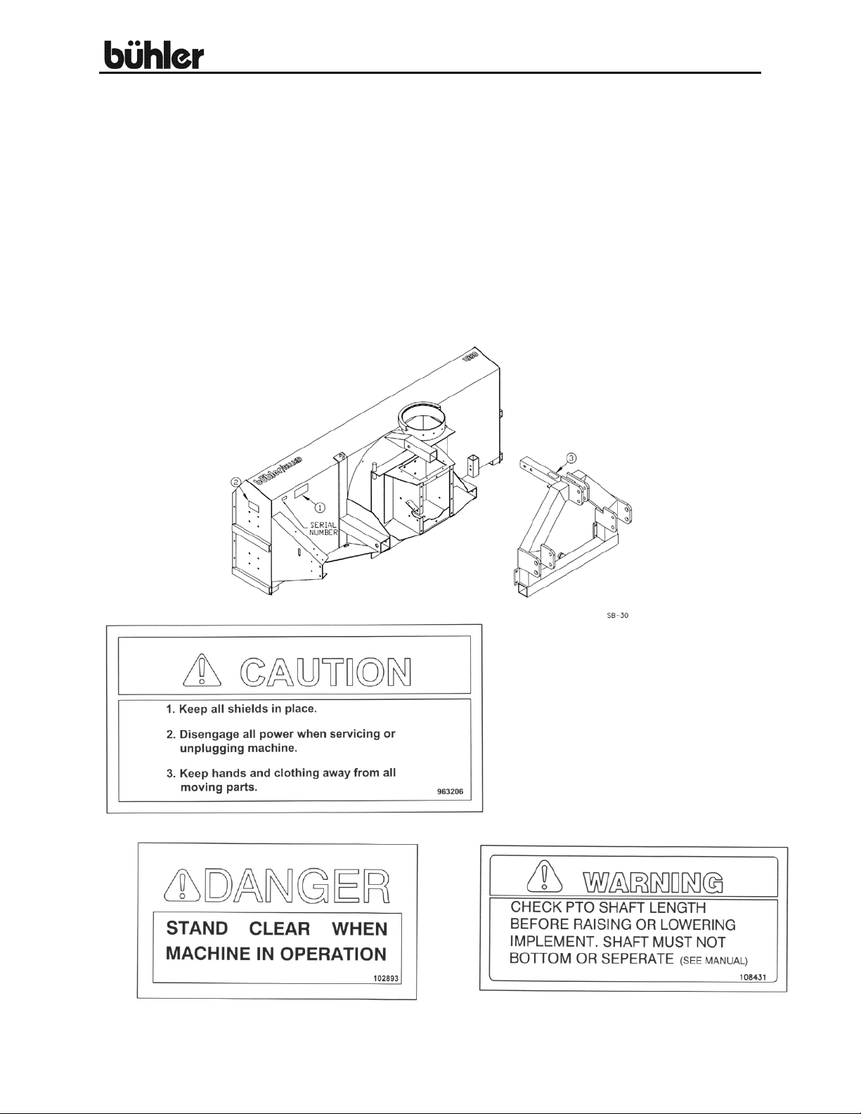
Replace safety signs immediately
should they become damaged, torn or
illegible. Obtain replacements from your
authorized dealer using the part
numbers shown.
#1
#2 #3
2
Page 6

108” Allied Snowblower
OPERATING INSTRUCTIONS
1. Do not operate the blower in the fully raised position. The three-point hitch on
some tractors raises high enough to cause the PTO shaft to bind. This can cause
damage to the PTO shaft and/or to the hitch and pins.
2. Depth of the cut can be partially controlled by tilting the blower forward or
backward. Adjust the top link of the tractor hitch so the snowblower is just slightly
tilted back when resting on the ground.
may cause the “U” joints to flutter resulting in PTO shear bolt failure.
3. The snowblower hitch should mount on three types of tractor hitches. A standard
category 2 uses the pins supplied without bushings. A standard category 3 uses
the pins supplied with the bushings. A category 3 quick hitch uses the pins with
bushings on the inside holes (holes are exactly 19” apart measured up and down.)
4. Adjust the lower link sway chains or blocks on the tractor to restrict movement of
the blower when operating.
5. The snowblowers may be purchased with either of two available spouts. Both
spouts have hydraulically controlled spout deflectors. The standard spout should
be suitable for all general snow blowing applications. The truckloader spout was
designed to blow snow directly onto the back of a truck. The maximum height of
the truck side you blow over should be approximately 10 feet.
6. Run the blower at low RPM to check operation before blowing snow.
7. The snowblower has shear bolts to protect the tractor and blower in case a large
object enters the blower. The PTO shaft uses two - 3/8" x 1" (grade 2) hex bolts
as shear bolts. The auger uses one - 5/16" x 1 ¼” (grade 5) hex bolt as a shear
bolt. Shear bolts should be fastened with a lock nut. These bolts must be kept
tight to prevent wear of the bolt and bolt holes.
8. Never run PTO shaft at over 1000 RPM.
9. Chain Tension: Slack on the lower side of the chain should be 3/8 to ½ inch.
CAUTION: Excessive backward tilt
3
Page 7

108” Allied Snowblower
OPERATING INSTRUCTIONS – cont’d.
10. Lubrication:
a) The spout clamps and rings should be periodically lubricated with gun
grease. This is particularly important on the truckloader spout which
turns harder than the standard spout due to the length and weight.
b) PTO shaft universal joints and splined slide should be greased daily.
c) Regularly oiling the chain will significantly increase the life of the chain.
d) The grease fitting on the hydraulic spout swivel arm and discharge
spout should be kept lubricated.
e) Use any 80-90 gear oil or multigrade with 80 minimum in the gearbox
up to the level plug height.
11. Periodically check all bolts for tightness. The bolt holding on the fan and the
bearing bolts are of particular importance.
12.
DANGER: Always stop blowing for servicing or unplugging. The PTO
should be disengaged before dismounting from the tractor.
13. Shear Sprocket: The shear sprocket (#46) should be checked at the beginning
of every season to make sure it will spin freely. Clean to loosen if necessary.
14. When replacing bearings or tightening a loose bearing collar, always tighten collar
in the
15.
CAUTION: Avoid raising or lowering snowblower under load. Doing so can
create excessive end pressure on the PTO shaft which could lead to bearing
failure on the snowblower.
direction of shaft rotation using a center punch or a similar tool.
4
Page 8

108” Allied Snowblower
ASSEMBLY INSTRUCTIONS
1. Hitch Assembly: With lower hitch tubes (#3) turned as shown in drawing, slide
them into the sleeves welded to the main body. These tubes are adjustable to two
different positions. The correct position for each individual tractor will be
determined when mounting the snowblower on the tractor (see section 4). Start
with the tubes pulled out to the last hole. These tubes are connected to the
snowblower with a 1 ¼” x 5 ½” pin (#6) and a hair pin clip (#12). Slide the threepoint hitch (#2) into the top sleeve on the snowblower body and hold in place with
a 1" x 4 3/8" pin (#7) and a hair pin clip (#12). Bolt the bottom of the hitch to the
ends of the hitch tubes using ½” x 2” hex bolts, lock washers, flat washers and hex
nuts.
2. Spout Assembly: Mount the discharge spout (#64 or #73) using the spout clamp
(#22) bolted to the spout ring on the snowblower. Lubricate the spout ring and
clamp. Mount the 5” stroke cylinder (#68) on the spout as shown in the drawing.
CAUTION: The ports in the cylinder are both 9/16" orb. Be sure that the
bottom edge of the deflectors are properly fitted in the guides before using the
hydraulic control.
3. Hydraulic Spout Swivel:
a) Bolt the cylinder arm base (#17) to the bottom of the hitch using 5/8” x 2”
hex bolt, lock washers and hex nuts. NOTE: There are three sets of
holes. The hole used to bolt on this base must match with the holes used
to assemble the hitch in the hitch tubes (i.e. 1
b) Mount the spout swivel (#16) onto the swivel pin welded to the back
corner of the fan housing using a 1 ¼” i.d. flat washer (#31) and a ¼” x
1 ¾” cotter pin (#32)
c) Wrap cable (#18) around spout and clamp to the ends of the swivel
using 3/8” cable clamps (#19).
d) With the spout turned forward and the swivel arm centered with the spout,
clamp the cable to the spout cable anchor using another cable clamp.
Ensure that the spout is not jammed and that there is no slack in the
cable
e) Use a standard 8” stroke cylinder (20 ¼” min., 28 ½” max. pin centers).
st
hole, second hole, etc.)
5
Page 9

108” Allied Snowblower
ASSEMBLY INSTRUCTIONS - Cont'd.
4. Mounting Blower on Tractor:
a) Mount the blower on a tractor with a category 2 or 3 standard hitch or a
category 3 quick hitch. The hitch as two holes both at the top of the hitch
and at each lift arm. When using a quick hitch, the pins must be in the
inside
point hitch. The lift arm pins also have a narrow spacing for category 2
and a wide spacing for category 3.
b) Using tape or a bright colored marking pen, mark on the outer shields of
the PTO the position where the shaft is completely pushed together and
the position where you have a 4" overlap. Watch these marks when
moving the blower through all possible operating angles to see that the
PTO shaft stays within this range. Slide the hitch in if necessary to keep
the PTO shaft in this operating range. Do not forget to change the
position of the cylinder arm (#17) by the same distance that you move the
hitch.
c) With the engine on the tractor shut off, attach the PTO shaft. The
tractor end has a 1 3/8" 21 spline end with a spring loaded locking collar.
The snowblower end has a clamp style yoke with a 3/8” keyway. Slide the
yoke onto the 1 ¾” jackshaft with the 3/8" key supplied. Lock the yoke in
place with the 5/8" x 3 ¼” bolt and lock nut fitted through the groove in the
gearbox shaft. After tightening the bolt, insert and tighten the 3/8" socket
set screw supplied.
d) Always check to see that both ends of the PTO shaft are securely
attached every time the snowblower is used. This should always be done
with the tractor engine off.
set of holes. Use the outside set of holes with a standard three-
6
Page 10
108” Allied Snowblower
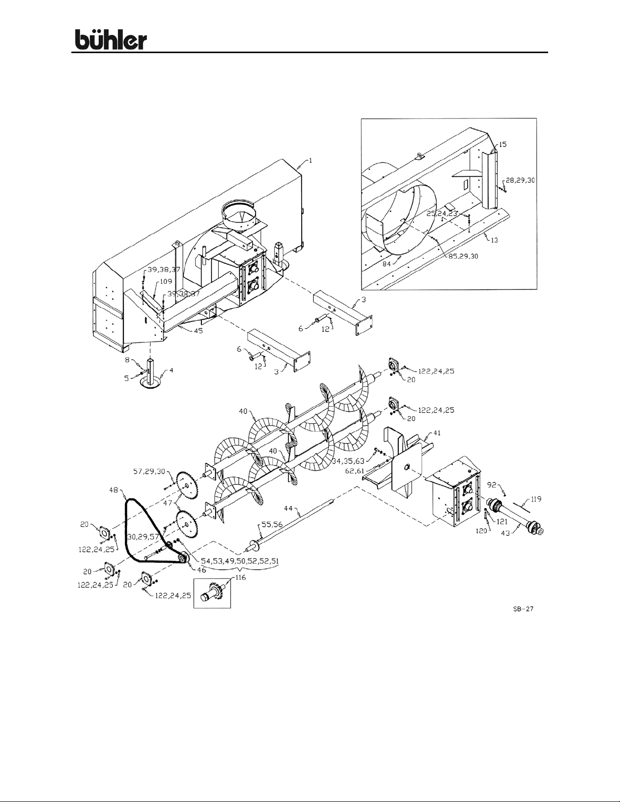
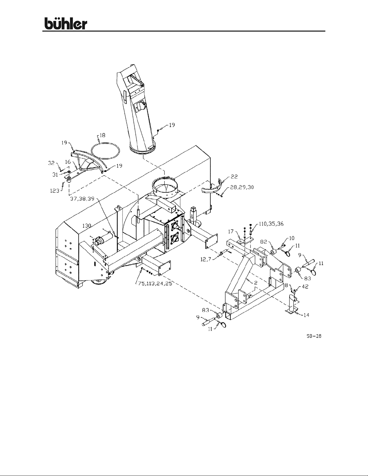
108” SNOWBLOWER
7
Page 11
108” Allied Snowblower
8
Page 12
108” Allied Snowblower
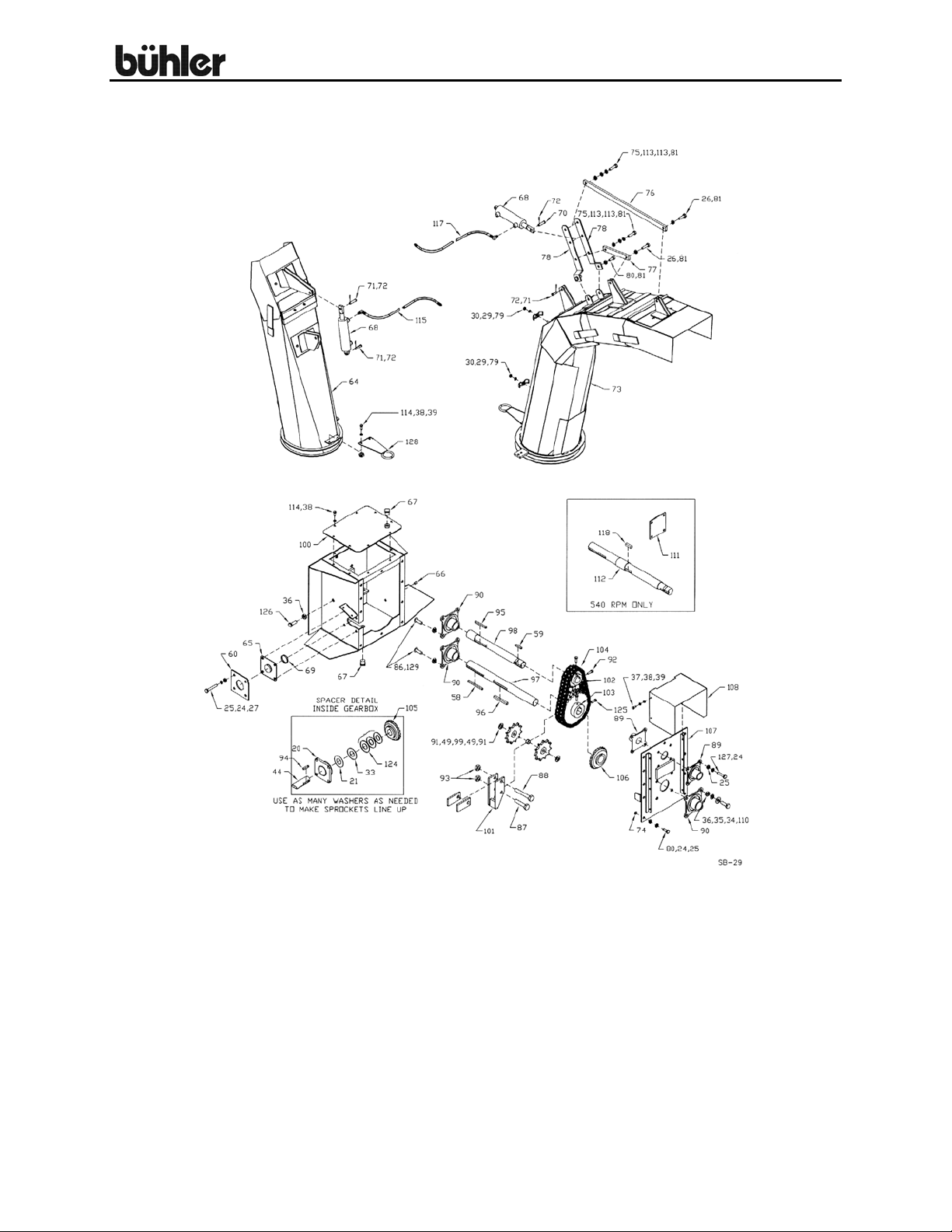
108” SNOWBLOWER GEARBOX & SPOUTS
9
Page 13

108” Allied Snowblower
WHEN ORDERING PARTS
Always give your dealer the Model, Color and Serial Number of your machine to assist
him in ordering and obtaining the correct parts. Use the exploded view and tabular
listing of the area of interest to exactly identify the required part.
108" Snowblower
Item # Part # Description
1 906491A Main Body Weldment
2 FX9244 3-point Hitch Weldment (902129)
3 965307A Lower Hitch Tube (4''SQ. X 29 1/2'')
4 902407 Skid Plate Weldment
F6707 Skid Plate Bundle
5 900712 Skid Pin
6 965205A Lower Hitch Tube Pin (1 1/4'' X 5 1/2'')
7 965206A Upper Hitch Tube Pin (1'' X 4 3/8'')
8 961012 #16 Hair Pin Clip
9 967461 Lift Pin Cat 2-3
10 965910 Top Lift Pin (Category.2)
11 965911 7/16'' Linch Pin
12 12779 #9 Hair Pin Clip
13 965209A Cutting Edge
14 965308A Jack Stand
15 965211A Chain Guard
16 965302 Hydraulic Swivel Arm
17 965213A Cylinder Arm Base
18 965654 3/8'' X 80'' Cable
19 964264 3/8'' Cable Clamp
20 968632 1 1/2'' Housing W/ Bearing - 4 Bolt
21 9812443 1 1/2'' x 18GA Narrow Rim Washer
22 965215A Spout Clamp
23 967475 1/2'' X 1 3/4'' Flush Head Bolt (skt) (pl)
24 81637 1/2'' Lock Washer (pl)
25 81636 1/2'' Hex Nut (pl)
26 87553 1/2'' X 1 3/4'' Hex Bolt (pl)
27 81628 1/2'' X 3 1/4'' Hex Bolt (pl)
28 86170 3/8'' X 1'' Hex Bolt (pl)
29 81593 3/8'' Lock Washer (pl)
30 81592 3/8'' Hex Nut (pl)
31 9812487 1 1/4'' x 10GA Narrow Rim Washer (pl)
32 81210 1/4'' X 2'' Cotter Pin (pl)
33 9812444 1 1/2'' x 14GA Narrow Rim Washer
34 81678 5/8'' BS Flat Washer (pl)
10
Page 14

108” Allied Snowblower
35 81677 5/8'' Lock Washer (pl)
36 81676 5/8'' Hex Nut (pl)
37 81549 5/16'' X 3/4'' Hex Bolt (pl)
38 81569 5/16'' Lock Washer (pl)
39 81568 5/16'' Hex Nut (pl)
40 965216 Auger (15'' O.D. X 107 3/8'' long)
41 902902 4-Blade Fan Weldment
42 965294A Jack Stand Pin
43 F9231 Standard PTO (1 3/8'' X 21 spline)
F9232 Optional PTO (1 3/4'' X 20 spline)
F9233 540 RPM PTO (1 3/8'' X 6 spline)
44 965280 Drive Shaft
45 965281A Drive Shaft Guard
46 965221A Shear Sprocket (13T, #80)
47 965222 Flighting Sprocket (40T, #80)
48 965282 Roller Chain (#80 X 109 link w/ Connector & Offset)
965273 #80 Offset Link only
49 965224A Idler Sprocket (11T. #80, 3/4'' bore)
50 965225A Idler Spacer (1 1/4'' O.D. 3/4'' i.d. X 2 5/16''lg)
51 811751 3/4'' X 5'' Hex Bolt (pl)
52 81702 3/4'' B.S. Flat Washer (pl)
53 81701 3/4'' Lock Washer (pl)
54 81700 3/4'' Hex Nut (pl)
55 81552 5/16'' X 1 1/4'' GR. 5 Hex Bolt (pl)
56 812362 5/16'' Lock Nut (pl)
57 811792 3/8'' X 1 1/2'' Hex Bolt (pl)
58 965226 Fan Key (3/8'' X 3/8'' X 5'')
59 968807 PTO Key (3/8'' X 3/8'' X 2'')
60 965296 Bearing Spacer
61 963030 1/2'' X 3'' Sq. Hd. Set Screw (pl)
62 984077 1/2'' Jam Nut (pl)
63 84270 5/8'' X 1 3/4'' Hex Bolt (pl)
64 F9241 Standard Spout Weldment
65 965647 1 1/2'' Oil Seal Plate
66 967451 1/2'' Solid Pipe Plug
67 967452 1'' Solid Pipe Plug
68 24930 Cylinder 1.75DIA X 5.0 - 9/16'' ORB
69 967453 Oil Seal (CR #15142)
70 960913 1/2'' X 1 13/16'' Clevis Pin (pl)
71 961876 1/2'' X 1 1/2'' Clevis Pin (pl)
72 9812430 1/8'' X 1'' Cotter Pin (pl)
73 F9243 Truckloader Spout Assembly 10' (965306 - Weldment)
F9234 Truckloader Spout Assembly 7' (965309 - Weldment)
74 82111 #111 O-Ring
75 811791 1/2'' X 2'' Hex Bolt (pl)
11
Page 15

108” Allied Snowblower
76 965304 Spout Link - 28 1/8''
77 965305 Spout Link - 8 3/4''
78 965238 Cylinder Arm
79 965239 Hose Clamp
80 81620 1/2'' X 1 1/4'' Hex Bolt (pl)
81 812364 1/2'' Lock Nut (pl)
82 965266 CAT. 2-3 Top Link Pin Bushing
83 965267 CAT. 2-3 Lift Arm Bushing
84 965268 Fan Housing Liner
85 967431 3/8'' X 1'' Flat Head Bolt (pl)
86 905609 5/8'' X 2 1/4'' Flat Head Bolt (pl)
87 810149 3/4'' X 3 1/2'' Hex Bolt (pl)
88 905630 3/4'' X 5'' Idler Bolt
89 906497 1 3/4'' Housing w/bearing (Ductile)
965283 1 3/4'' Bearing w/collar
906498 1 3/4'' Ductile Housing Only
90 906499 2'' Housing w/bearing (Ductile)
967375 2'' Bearing w/collar
906500 2'' Ductile Housing Only
91 84050 3/4'' SAE Flat Washer (pl)
92 985639 3/8''Dia X 1/2'' Socket Set Screw
93 812365 3/4'' Lock Nut (pl)
94 965821 3/8'' X1 3/4'' Key
95 965284 3/8'' X 3 3/4'' Key
96 965285 1/2'' X 4 1/2'' Key
97 965286 Fan Shaft (2'' X 23'')
98 965667 Jack Shaft (2''/1 3/4'' X 18 3/4'')
99 965288 Idler Sprocket Spacer
100 965660 Gearbox Cover
101 965290 Chain Tightener Weldment
102 965269 Sprocket 15T, #80 DBL, 1 3/4'' B
103 965270 Sprocket 28T, #80 DBL, 2'' B
104 965271 Chain (#80 Dbl x 40 link w/ Connector)
105 965275 Gear 22T, 1 1/2'' Bore
106 965274 Gear 22T, 2'' Bore
107 906496 Gearbox Front Cover Plate
108 965655 PTO Guard
109 965295A Idler Shield
110 84299 5/8'' X 2'' Hex Bolt (pl)
111 965298A 1 3/4'' Bearing Cover (540 RPM only)
112 965299 540 RPM Fan Shaft
113 81638 1/2'' BS Flat Washer (pl)
114 812026 5/16'' X 1'' Hex Bolt (pl)
115 115370 3/8'' X 114'' Hose w/90 Degree Elbow
116 905080 Idler Assembly - Parts Only
12
Page 16

108” Allied Snowblower
117 115371 3/8'' X 156'' Hose w/ fittings
115369 3/8 X 156 Hose 1/2 MNPT X 9/16 SWFJIC
811918 Elbow 90deg 9/16 SWMORB X 9/16 MJIC
886786 Elbow 90deg 1/4'' MNPT X 9/16'' MJIC
118 902127 1/2'' x 1 3/4'' Gear Key (540 RPM)
119 936402 PTO Safety Chain
120 967433 5/8'' x 3 1/4'' Hex Bolt (pl)
121 812482 5/8'' Lock Nut (pl)
122 84277 1/2'' x 1 1/2'' Hex Bolt (pl)
123 967164 Pound-In Grease Fitting
124 967135 1 1/2'' x 10GA Narrow Rim Washer (pl)
125 967474 3/8'' x 1 1/4'' Sq Hd Set Screw
126 84270 5/8'' x 1 3/4'' Hex Bolt (pl) (540 RPM)
968898 5/8'' x 4'' Sq Hd Set Screw (1000 RPM)
127 81624 1/2'' x 2 1/4'' Hex Bolt (pl)
128 907590 Spout Hose Holder
129 812482 5/8" Lock Nut (pl)
130 909277 Manual holder
13
Page 17
108” Allied Snowblower
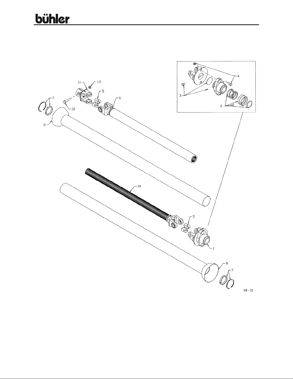
108” ALLIED SNOWBLOWER PTO
14
Page 18

108” Allied Snowblower
108'' SNOWBLOWER PTO SHAFT PARTS LIST
Item # Part # Description
F9231 Standard Shaft (21 Spline, 1 3/8'') - 1000 RPM
F9232 Optional Shaft (20 Spline, 1 3/4'') - 1000 RPM
F9233 540 RPM Shaft (6 Spline, 1 3/8'')
1 936413 Standard Shear Assembly (21 Spl, 1 3/8'')
936422 Shear Hub Only (21 Spl, 1 3/8'')
936414 Optional Shear Assembly (20 Spl, 1 3/4'')
936423 Shear Hub Only (20 Spl, 1 3/4'')
936429 540 RPM Shear Assy (6 Spl, 1 3/8'')
936424 Shear Hub Only (6 Spl, 1 3/8'')
936428 Shear Yoke Only (All Sizes)
2 936415 Safety Slide Lock Repair Kit (20 Spl, 1 3/4'')
936199 Safety Slide Lock Repair Kit (7 & 21 Spl, 1 3/8'')
3 936249 Shear Assy Repair Kit
4 908890 Shear Bolt - 3/8'' x 1'' (Gr.2) - 1000 RPM (Pack of 10)
908846 Shear Bolt - 3/8'' x 1'' (Gr.8) - 540 RPM (Pack of 10)
5 936197 Repair Kit (Option)
906548 Extended Life Repair Kit (Std)
6 936426 Yoke & Tube (Splined)
7 936417 Bearing & Snap Ring Kit
8 936418 Inner Guard
9 936419 Outer Guard
10 936425 Yoke & Shaft (Splined)
11 936421 Clamp Yoke
12 967433 5/8'' x 3 1/4'' Bolt
13 812482 5/8'' Lock Nut
15
Page 19

108” Allied Snowblower
SHIPPING KIT AND BUNDLE NUMBERS
The following is a list of kit numbers for this product and the bundle numbers,
descriptions, and quantities for each kit.
QUANTITY BUNDLE NO. DESCRIPTION
YC1080C 1000 RPM WITH STANDARD SPOUT
1 FX9244 Hitch
1 F9241 Standard Spout
1 FX0199 Body Assembly
1 F0560 Deflector Cylinder & Hose Kit
1 F9231 PTO 1000 rpm (1 3/8” x 21 spline)
YC1080CT 1000 RPM WITH TRUCKLOADER SPOUT
1 FX9244 Hitch
1 F9243 Truckloader Spout
1 FX0199 Body Assembly
1 F9118 Deflector Cylinder & Hose Kit
1 F9231 PTO 1000 rpm (1 3/8” x 21 spline)
YC1080D 540 RPM WITH STANDARD SPOUT
1 FX9244 Hitch
1 F9241 Standard Spout
1 FX0201 Body Assembly
1 F0560 Deflector Cylinder & Hose Kit
1 F9233 PTO 540 rpm (1 3/8” x 6 spline)
YC1080DT 540 RPM WITH TRUCKLOADER SPOUT
1 FX9244 Hitch
1 F9243 Truckloader Spout
1 FX0201 Body Assembly
1 F9118 Deflector Cylinder & Hose Kit
1 F9233 PTO 540 rpm (1 3/8” x 6 spline)
OPTIONAL BUNDLE NUMBERS
The following is a list of options available for the Kits listed above.
F9116 Swivel Arm Cylinder & Hose Kit
F9232 1000 rpm PTO (1 ¾” x 20 spline)
F9233 540 rpm PTO (1 3/8” x 6 spline)
Y907 7’ Truckloader Spout
- c/w Cylinder & Hoses
Y910 10’ Truckloader Spout
- c/w Cylinder & Hoses
16
Page 20

NOTES
Page 21

NOTES
Page 22

NOTES
Page 23

Page 24

Farm King Division
301 Mountain Street S.
Morden, MB R6M 1X7
Ph.: (204) 822-4467
Fax: (204) 822-6348
Allied/Inland Division
1260 Clarence Avenue
Winnipeg, MB R3T 1T2
Ph.: (204) 284-6100
Fax: (204) 477-2325
B.I.I. Division
1330 43
rd
Street N.W.
Fargo, ND 58102
Ph: (701) 282-7014
Fax: (701) 282-5865
B.C., Abbotsford
(604) 864-2665
AB, Edmonton
(780) 962-6991
SK, Regina
(306) 781-2300
ON, Woodstock
(519) 539-0435
QC, Dorion
(450) 455-4840
AR, West Memphis
(870) 732-3132
GA, Stone Mountain
(770) 908-9439
ID, Meridian
(208) 887-6006
IN, Clarksville
(812) 284-3376
KS, Wichita
(316) 265-9577
MN, Lakeville
(952) 469-5267
MT, Billings
(406) 248-7771
ND, Bismarck
(701) 223-1886
Burando Hill
Katanning
W. Australia
011-618-98-214422
011-52-158-90306
Chihuahua, Mexico
ND, Fargo
(701) 282-7003
NE, Blair
(402) 426-8211
OH, Youngstown
(330) 793-0862
OR, Beaverton
(503) 641-1865
SD, Huron
(605) 352-8616
TX, Houston
(713) 928-2632
UT, Salt Lake City
(801) 972-4321
WI, Portage
(608) 742-1370
John Kerr Equipment Ltd.
Wilcoxholm Farm
Linlithgow, W. Lothian
Scotland
011-441-506-842280
Skovde, Sweden
011-46-500-452651
Naestved, Denmark
011-45-557-29511
Buhler Manufacturing
301 Mountain Street S.
Morden MB.
R6M 1X7
Ph.: (204) 822-4467
Fax: (204) 822-6348
www.buhler.com
Printed in Canada
 Loading...