

Page 1
Page 2

Page 3

96” Allied Snowblower
TABLE OF CONTENTS
DESCRIPTION PAGE
Warranty......................................................................1
Safety Instructions & Safety Sign Locations ................2
Operating Instructions..................................................3
Assembly Instructions..................................................5
96” Allied Snowblower Drawings..................................8
96” Allied Snowblower Parts List .................................10
96” Allied Snowblower PTO Drawing...........................12
96” Allied Snowblower PTO Parts Lists .......................13
Gearbox Assembly Drawing & Parts List.....................15
Cylinder Assembly Drawings & Parts Lists..................16
Shipping Kit and Bundle Numbers...............................17
Page 4

96” Allied Snowblower
WARRANTY POLICY
Buhler Manufacturing products are warranted for a period of twelve (12) months (90 days for
commercial application) from original date of purchase, by original purchaser, to be free from
defects in material and workmanship under correct, normal agricultural use and proper
applications.
Buhler Manufacturing’s obligations under this warranty shall be limited to the repair or
exchange, at Buhler Manufacturing’s option, of any Buhler Manufacturing product or part which
proves to be defective as provided. Buhler Manufacturing reserves the right to either inspect
the product at the buyer’s location or have it returned to the factory for inspection.
The above warranty does not extend to goods damaged or subject to accident, abuse or misuse
after shipment from Buhler Manufacturing’s factory, nor to goods altered or repaired by anyone
other than an authorized Buhler Manufacturing representative.
Buhler Manufacturing makes no Express Warranties other than those, which are specifically
described. Any description of goods, including any references and specifications in catalogues,
circulars and other written material published, is for the sole purpose of identifying goods and
shall conform to such descriptions. Any sample or model is for illustrative purposes only and
does not create an Express Warranty that the goods conform to sample or model shown.
The purchaser is solely responsible for determining suitability of goods sold. This warranty is
expressly in lieu of all other warranties expressed or implied. Buhler Manufacturing will in no
event be liable for any incidental or consequential damages whatsoever. Nor for any sum in
excess of the price received for the goods for which liability is claimed.
WARRANTY CLAIMS:
Warranty requests must be prepared on Buhler Manufacturing Warranty Claim Forms with all
requested information properly completed. Warranty Claims must be submitted within a thirty
(30) day period from date of failure repair.
WARRANTY LABOR:
Any labor subject to warranty must be authorized by Buhler Manufacturing. The labor rate for
replacing defective parts, where applicable, will be credited at 100% of the dealer’s posted shop
rate. Defective parts will receive an extra 10% discount to assist with freight or other incidental
costs.
GOVERNMENT LEGISLATION:
Warranty terms and conditions are subject to Provincial or State legislation.
IMPORTANT FACTS:
Buckets and Bucket Tines Carry No Warranty
Bent Spears Carry No Warranty
Snowblower Fan Shafts Carry No Warranty
Mower Blades Carry No Warranty
Portable Auger Parts Have Two (2) Year Warranty
Loader Parts Have Two (2) Year Warranty
IMPORTANT NOTE: This warranty does not apply to rentals
1
Page 5
96” Allied Snowblower
SNOWBLOWER
This manual is for 96" Allied Snowblower with a quick coupling hitch. With this hitch, the
blower can be mounted on a tractor with either a quick hitch or the standard three-point
hitch. All 96" Allied snowblowers have a sealed oil bath gearbox. The snowblower is
the push type and will mount to a tractor with 540 rpm PTO. It is supplied with category
2 pins with conversion bushings to category 3 available. This 96" wide snowblower
comes with hydraulic chute control as standard equipment. A hand crank chute control
is available. There is a shear bolt on the auger and on the PTO shaft to protect the
machine from damage if a large object is picked up. Any smaller objects in the snow
will be thrown with it and could cause serious injury. Do not let anyone stand behind the
tractor in the area of the discharged snow.
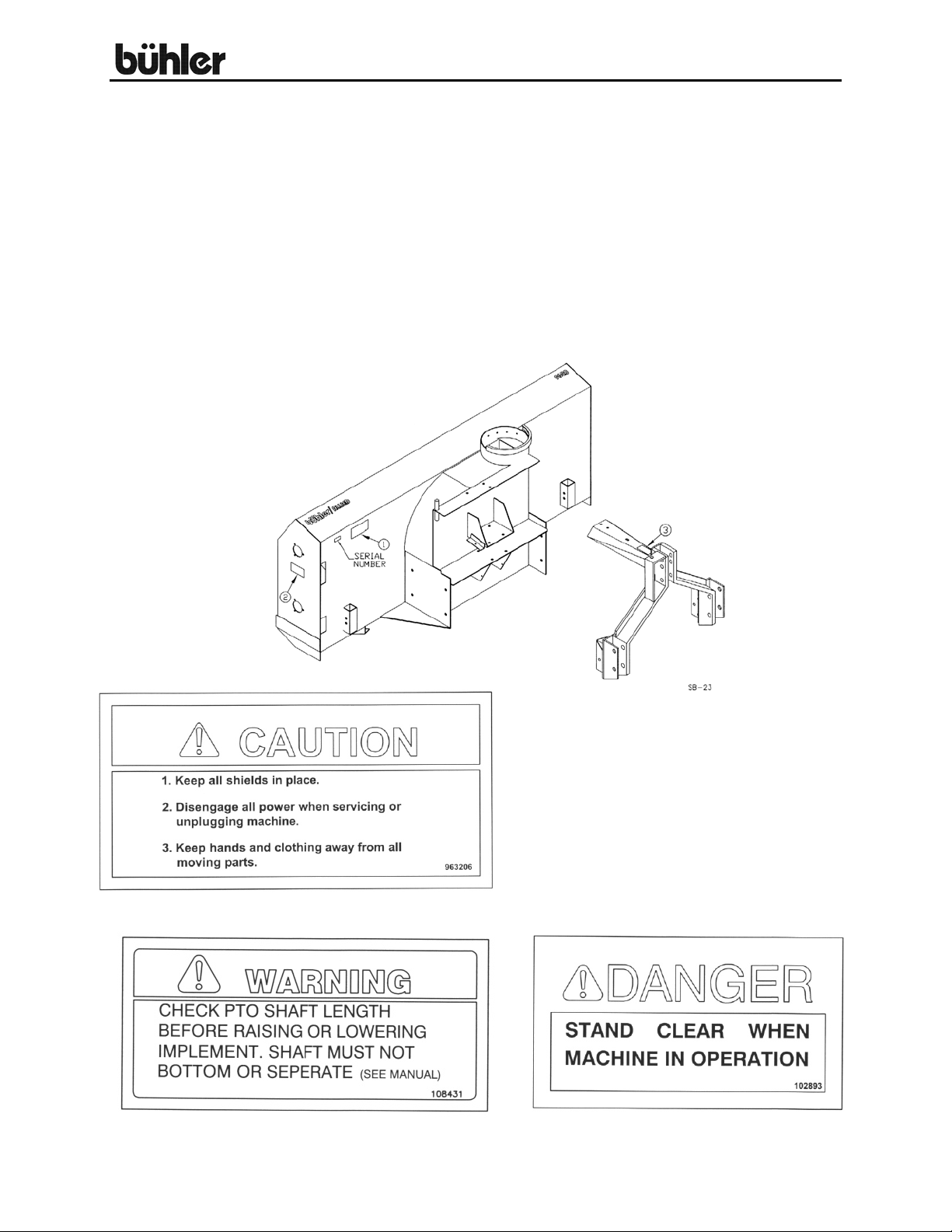
Replace safety signs immediately
should they become damaged, torn or
illegible. Obtain replacements from your
authorized dealer using the part
numbers shown.
#1
#3 #2
2
Page 6

96” Allied Snowblower
OPERATING INSTRUCTIONS
1. Do not operate the blower in the fully raised position. The three-point
hitch on some tractors rises high enough to cause the PTO shaft to bind.
This can cause damage to the PTO shaft and/or to the hitch and pins.
2. Depth of cut can be partially controlled by tilting the blower forward or
backward. Adjust the tractor quick hitch so the snowblower is just slightly
tilted back when resting on the ground.
CAUTION: Excessive backward tilt may cause the "U" joints to flutter
resulting in PTO shear bolt failure.
3. Run the blower at low rpm to check operation before blowing snow.
4. The snowblower has two shear bolts to protect the tractor and blower in
case a large object enters the blower. PTO shear bolt - two 5/16" x 1"
(Grade 8); Auger shear bolt – 5/16” x 1 ¼” (Grade 5). Shear bolts should
be fastened with a lock nut or two jam nuts. These bolts must be kept
tight to prevent wear of the bolt and bolt holes.
5. Never run PTO shaft at over 600 rpm.
6. Chain Tension: Slack on the lower side of the chain should be 3/8” to ½”.
7. Lubrication:
a) The spout clamps and rings should be periodically lubricated with gun
grease.
b) PTO shaft universal joints and square shaft slide should be greased
daily.
c) Regularly oiling the chain will significantly increase the life of the chain.
d) The grease fitting on the hydraulic spout swivel arm should be kept
lubricated.
e) Gearbox - Use any 80-90 gear oil or multigrade with 80 minimum.
8. Periodically check all bolts for tightness. The bolt holding on the fan and
the bearing bolts are of particular importance.
9. Danger: Always stop blowing for servicing or unplugging. The PTO
Should be disengaged before dismounting from the tractor.
10. Caution: Always check to see that both ends of the PTO shaft are
securely attached as per instructions every time you are preparing to use
the Snowblower.
3
Page 7

96” Allied Snowblower
OPERATING INSTRUCTIONS – cont’d
11. Shear Sprocket: The shear sprocket (#24) should be checked at the
beginning of every season to make sure it will spin freely. With time this
sprocket could corrode and seize which will not allow the shear bolt to
break if something jams in the snowblower auger. Clean to loosen if
necessary.
12. When replacing bearings or tightening a loose bearing collar, always
tighten collar in the direction of shaft rotation using a center punch or a
similar tool.
4
Page 8

96” Allied Snowblower
ASSEMBLY INSTRUCTIONS
1. Fasten the two quick hitch arms (#57) to the main body. Use eight 5/8” x
1 ¼” hex bolts, lock washers and hex nuts. Note: Lift arms for quick
coupling hitch are 30 ¾” long versus 35” for the standard three point hitch.
2. Bolt the quick hitch (#56) to the snowblower body using two ½” x 1 ¼” hex
bolts, lock washers and hex nuts. Fasten to the lift arms using three 5/8" x
1 ½” hex bolts on each lift arm. Insert a 1" top link pin at the top and two 1
1/8" lift pins at the bottom of the hitch.
3. Bolt the hitch cross brace (#2) underneath the two quick hitch arms using
two 5/8" x 1 ½” hex bolts, lock washers, flat washers and hex nuts.
4. Mount the discharge spout (#3) using the spout clamp (#51) bolted to the
spout ring on the snowblower. Lubricate the spout ring and clamp.
5.
d) Use a standard 8" stroke cylinder (20 ¼” min., 28 ¼” max. pin
e) NOTE: A hydraulic cylinder and hose kit to control the spout
6. Hand Crank (Option):
Hydraulic Spout Swivel:
a) Mount the swivel arm (#36) onto the swivel pin welded to the back
corner of the fan housing using a 1" ID flat washer (#37) and a 3/16"
x 1 ½” cotter pin (#52).
b) Wrap cable (#35) around spout and clamp to the ends of the swivel
using ¼” cable clamps (#16).
c) With the spout turned forward and the swivel arm centered with the
spout, clamp the cable to the spout cable anchor using another
cable clamp. Ensure that the spout is not jammed and that there is
no slack in the cable.
centers).
deflector is available as an option.
a) Fasten hand crank assembly (#50) using two ½” x 1 ¼” hex bolts,
lock washer and hex nuts.
b) Thread cable (#53) through hole in hand crank to even lengths and
wrap around the tube to each side of the hole four turns in opposite
directions.
c) Turn spout to center forward position and clamp cable to cable
anchor on far side of spout using clamp (#16).
5
Page 9

96” Allied Snowblower
ASSEMBLY INSTRUCTIONS – cont’d.
7. Mounting blower on tractor:
a) The pins supplied with the snowblower are for a category 2 quick
hitch. The quick coupling hitch has two holes both at the top of the
hitch and at each lift arm. When using a quick coupler, the pins
must be in the inside set of holes. Use the outside set of holes with
a standard three-point hitch.
b) Using tape or a bright colored marking pen, mark on the outer
shields the position where the shaft is completely pushed together
and the position where you have a 4"overlap. Watch these marks
when moving the blower through all possible operating
angles to see that the PTO shaft stays within this range.
c) With the engine on the tractor shut off, attach the PTO shaft. The
tractor end has a standard 6-spline end with a spring loaded locking
collar. The snowblower end has a clamp-style yoke with a 3/8" key
way. Slide the yoke onto the gearbox shaft with the 3/8" key
supplied. Lock the yoke in place with the 1/2" x 3" hex bolt and lock
nut fitted through the groove in the gearbox shaft. After tightening
the bolt, insert and tighten the 3/8" socket set screw supplied.
Caution: Always check to see that both ends of the PTO
shaft are securely attached every time the Snowblower is used.
This should always be done with the tractor engine off.
d) Check that the PTO shaft does not bottom or separate with the
blower in the extreme high and low positions. A longer optional
PTO shaft is available if the standard shaft is too short. Check for
free movement of all parts in various raised positions; particularly
the PTO shaft.
e) NOTE: Excessive U-joint wear and shear pin failure may result if
the tractor PTO angle exceeds 20 °. The drawing below gives an
approximate way to check this angle. With the PTO half extended,
the tractor output should not be over 32 inches high. Use 34 inches
if the PTO is nearly fully extended and 30 inches if it is nearly
compressed.
6
Page 10

96” Allied Snowblower
ASSEMBLY INSTRUCTIONS – cont’d.
8. PTO SHIELD
All snowblowers are supplied with a PTO shield (#61). To install, remove
the two rear bolts at the top of the gearbox (#38). Bolt the PTO shield to
the gearbox by the hinges using these same bolts. A utility spring (#62)
keeps the shield in place. Hook one end of the spring in the hole in the
shield and the other end to the hole in the brace under the gearbox.
CAUTION: Do not run the snowblower without this shield in place.
REFILLING GEARBOX WITH OIL:
If the gearbox requires refilling with oil because of repairs to the gearbox,
add oil to the level shown in drawing. Check the level regularly using the
plug in the lid. The correct level is even with the bottom of the plug.
7
Page 11

96” Allied Snowblower
96” SNOWBLOWER W/QUICK HITCH
8
Page 12

96” Allied Snowblower
9
Page 13

96” Allied Snowblower
WHEN ORDERING PARTS
Always give your dealer the Model, Color and Serial Number of your machine to assist
him in ordering and obtaining the correct parts. Use the exploded view and tabular
listing of the area of interest to exactly identify the required part.
96'' ALLIED SNOWBLOWERS
ITEM PART # DESCRIPTION
1 902403A Main Body
2 965959A Hitch Cross Brace, 1 1/2'' x 39 1/2''
3 965648 Spout Weldment
4 965904 Auger
5 965905 Fan Assy (Standard 3-Blade)
965448 Fan Assy (Optional 4-Blade)
6 812362 5/16'' Lock Nut (pl)
7 84072 3/8'' x 3/4'' Hex Bolt (pl)
8 81619 1/2'' x 1'' Hex Bolt (pl)
9 81620 1/2'' x 1 1/4'' Hex Bolt (pl)
10 81637 1/2'' Lock Washer (pl)
11 81636 1/2'' Hex Nut (pl)
12 965910 Top Link Pin (Cat. 2)
13 965911 Linch Pin
14 84111 1/2'' x 1 1/4'' Sq. Hd. Set Screw (pl)
15 984077 1/2'' Jam Nut (pl)
16 961658 1/4'' Cable Clamp
17 84268 5/8'' x 1 1/2'' Hex Bolt (pl)
18 81677 5/8'' Lock Washer (pl)
19 81678 5/8'' B.S. Flat Washer (pl)
20 81569 5/16'' Lock Washer (pl)
21 81568 5/16'' Hex Nut (pl)
22 965912 40 Tooth Sprocket, #60, 1 3/8'' Bore
23 965962A Idler Sprocket, #60 x 13 Tooth
24 965914A 13 Tooth Sprocket, #60, 1 1/4'' Bore
25 965972 Roller Chain (#60 x 117 Link w/ Conn & Offset)
26 961876 1/2'' x 1 1/2'' Clevis Pin (pl)
27 81593 3/8'' Lock Washer (pl)
28 81592 3/8'' Hex Nut (pl)
29 81676 5/8'' Hex Nut (pl)
30 86170 3/8'' x 1'' Hex Bolt (pl)
31 965917 1 3/8'' Bearing w/ Collar
32 961675A Flange Bearing (72MS)
33 965963A Chain Guard
34 965919A Drive Shaft Guard
10
Page 14

96” Allied Snowblower
35 965964 1/4'' Cable x 70'' Long
36 965923 Swivel Arm
37 967140 1'' x 10ga Narrow Rim Washer (pl)
38 BU50505 Gearbox Complete w/o Oil
39 F0585 PTO Shaft Complete
40 965925A Drive Shaft
41 968807 3/8'' x 3/8'' x 2'' Key
42 81627 1/2'' x 3'' Hex Bolt (pl)
43 902377 3/8'' x 3/8'' x 4 3/4'' Key
44 81552 5/16'' x 1 1/4'' Gr. 5 Hex Bolt (pl)
45 811702 5/8'' x 1 1/4'' Hex Bolt (pl)
46 961676 1 1/4'' Bearing w/ Collar
47 967164 Pound-In Grease Fitting
48 81549 5/16'' x 3/4'' Hex Bolt (pl)
49 81620 1/2'' x 1 1/4'' Hex Bolt (pl)
50 965803 Hand Crank Weldment
51 965970A Spout Clamp
52 9812433 3/16'' x 1 1/2'' Cotter Pin (pl)
53 965927 3/16'' Cable x 100'' Long
54 84289 5/8'' x 3'' Hex Bolt (pl)
55 965928A Idler Spacer, 3/4'' Long
56 FX9204 Allied Quick Hitch
57 965952A Quick Hitch Arm
59 812026 5/16'' x 1'' Hex Bolt (pl)
60 965966 Quick Hitch Lift Pin (Cat. 2)
61 908715 PTO Shield
62 960135 PTO Shield Spring
63 965968 Idler Shield
64 812364 1/2'' Lock Nut (pl)
65 988999 3/8'' x 3/8'' Socket Set Screw (br)
66 81593 3/8'' Lock Washer (pl)
67 81592 3/8'' Hex Nut (pl)
68 965646 Spout Adjustment Bar
69 903523 1/2'' x 1 1/2'' Adjustment Pin Weldment
70 961012 #16 Hair Pin Clip
71 902407 Skid Plate Weldment
F6707 Skid Plate Bundle
72 900712 Skid Pin (5/8'' x 3'')
73 86171 3/8'' x 1 1/4'' Hex Bolt (pl)
74 FX9102 Hand Crank Assembly (Complete Kit)
75 936402 PTO Safety Chain
76 909277 Manual Holder
11
Page 15

96” Allied Snowblower
96” ALLIED SNOWBLOWER PTO
(Standard and Optional Long)
12
Page 16

96” Allied Snowblower
96" ALLIED SNOWBLOWER PTO (Standard)
Item # Part # Description
F0585 Shaft Complete
907987 Tractor Half of PTO (Shear)
907988 Implement Half of PTO (Clamp Yoke)
1 907989 Shear Assembly
2 936199 Safety Slide Lock Repair Kit
3 936249 Shear Assembly Repair Kit
4 903297 Shear Bolt - 5/16" x 1" (Grade 8) (Pack of 10)
5 936197 Repair Kit (Option)
906548 Extended Life Repair Kit (Std.)
6 907994 Yoke & Tube
7 907991 Nylon Bearing
8 907993 Inner Shield
9 907992 Outer Shield
10 907990 Yoke & Shaft
11 907995 Clamp Yoke
12 81627 1/2" x 3" Hex Bolt (pl)
13 812364 1/2" Lock Nut (pl)
14 908002 Shear Yoke
15 936411 6 Spl. Shear Hub
(Collar, Spring, Ret. Ring, 2-Pawls)
(3/8" x 1/2" Bolt, Lube, Blank, 31-1/4" Balls)
13
Page 17

96” Allied Snowblower
96" ALLIED SNOWBLOWER PTO (Optional Long)
Item # Part # Description
F0586 Shaft Complete
907996 Tractor Half of PTO (Shear)
907997 Implement Half of PTO (Clamp Yoke)
1 907989 Shear Assembly
2 936199 Safety Slide Lock Repair Kit
3 936249 Shear Assembly Repair Kit
4 903297 Shear Bolt - 5/16" x 1" (Grade 8) (Pack of 10)
5 936197 Repair Kit (Option)
906548 Extended Life Repair Kit (Std.)
6 907998 Yoke & Tube
7 907991 Nylon Bearing
8 907999 Inner Shield
9 908000 Outer Shield
10 908001 Yoke & Shaft
11 907995 Clamp Yoke
12 81627 1/2" x 3" Hex Bolt (pl)
13 812364 1/2" Lock Nut (pl)
14 908002 Shear Yoke
15 936411 6 Spl. Shear Hub
(Collar, Spring, Ret. Ring, 2-Pawls)
(3/8" x 1/2" Bolt, Lube, Blank, 31-1/4" Balls)
14
Page 18

96” Allied Snowblower
96” ALLIED SNOWBLOWER GEARBOX
960 FK, 85", & 96" ALLIED SNOWBLOWER GEARBOX PARTS LIST
Item # Part # Description
BU50505 Gearbox Complete
1 BU50310 Gearbox Casting Only
2 BU500089-3 Pipe Plug
3 BU50457 Gearbox Cover
4 BU500167-1 Relief Valve
5 BU50458 Gearbox Gasket
6 BU50507 Cross Shaft
7 BU50502 Pinion Shaft
8 BU50329 Bevel Gear - 1 1/2" Bore
9 BU50331 Bevel Gear - 1 3/8" Bore
10 BU50428 Staking Lock Nut
11 BU50444 Staking Lock Nut
12 BU50422-1 Oil Seal (3 used)
13 BU50415 Retainer Ring (4 used)
14 BU575902 Bearing Cup (2 used)
15 BU575901 Bearing Cone (2 used)
16 BU50429 Key
17 BU50210X Shim Set
18 BU575907 Bearing Cup (2 used)
19 BU575906 Bearing Cone (2 used)
20 BU500397-6 Hex Bolt 5/16'' NC x 5/8'' GR5 (pl)
21 BU50417-1 Key
15
Page 19

96” Allied Snowblower
3.5 x 8 CYLINDER ASSEMBLY
Item # Part # Description
1 24804 Tube Weldt
2 113934 Piston Rod 1.5 Dia
3 X2098 Seal Kit
24803 Cyl Complete
1.75 X 5 CYLINDER ASSEMBLY
Item # Part # Description
24930 Cyl Complete
1 115367 Tube Weldt
2 112104 Shaft Weldt 1.0 Dia
3 X2669 Seal Kit
16
Page 20

96” Allied Snowblower
SHIPPING KIT AND BUNDLE NUMBERS
The following is a list of kit numbers for this product and the bundle numbers,
descriptions, and quantities for each kit.
QUANTITY BUNDLE NO. DESCRIPTION
YC9620Q 96” Allied Snowblower w/Hydraulic Chute Control & 3-Blade Fan
1 F0624A Body Assembly
1 FX9204 Quick Hitch
1 F9211 Spout Assembly
1 F0585 Standard PTO
YC9620Q-4 96” Allied Snowblower w/Hydraulic Chute Control & 4-Blade Fan
1 FX9204 Quick Hitch
1 F0625A Body Assembly
1 F9211 Spout Assembly
1 F0585 Standard PTO
YC9620QL 96” Allied Snowblower w/Hydraulic Chute Control, Long PTO &
3-Blade Fan
1 F0624A Body Assembly
1 FX9204 Quick Hitch
1 F9211 Spout Assembly
1 F0586 Long PTO
YC9620QL-4 96” Allied Snowblower w/Hydraulic Chute Control, Long PTO &
4-Blade Fan
1 FX9204 Quick Hitch
1 F0625A Body Assembly
1 F0586 Long PTO
1 F9211 Spout Assembly
OPTIONAL BUNDLE NUMBERS
The following is a list of options available for the Kits listed above.
F0585 – Standard PTO
F0586 – 36” PTO (optional long)
FX9102 – Hand crank Kit
FX9107 – Hydraulic Chute Control Kit
F9116 – Hydraulic Cylinder & Hose Kit for Spout Swivel
F9117 – Spout Deflector Cylinder & Hose Kit
Y902 – Quick Hitch Kit
17
Page 21

NOTES
Page 22

NOTES
Page 23

Page 24

Farm King Division
301 Mountain Street S.
Morden, MB R6M 1X7
Ph.: (204) 822-4467
Fax: (204) 822-6348
Allied/Inland Division
1260 Clarence Avenue
Winnipeg, MB R3T 1T2
Ph.: (204) 284-6100
Fax: (204) 477-2325
B.I.I. Division
1330 43
rd
Street N.W.
Fargo, ND 58102
Ph: (701) 282-7014
Fax: (701) 282-5865
B.C., Abbotsford
(604) 864-2665
AB, Edmonton
(780) 962-6991
SK, Regina
(306) 781-2300
ON, Woodstock
(519) 539-0435
QC, Dorion
(450) 455-4840
AR, West Memphis
(870) 732-3132
GA, Stone Mountain
(770) 908-9439
ID, Meridian
(208) 887-6006
IN, Clarksville
(812) 284-3376
KS, Wichita
(316) 265-9577
MN, Lakeville
(952) 469-5267
MT, Billings
(406) 248-7771
ND, Bismarck
(701) 223-1886
Burando Hill
Katanning
W. Australia
011-618-98-214422
011-52-158-90306
Chihuahua, Mexico
ND, Fargo
(701) 282-7003
NE, Blair
(402) 426-8211
OH, Youngstown
(330) 793-0862
OR, Beaverton
(503) 641-1865
SD, Huron
(605) 352-8616
TX, Houston
(713) 928-2632
UT, Salt Lake City
(801) 972-4321
WI, Portage
(608) 742-1370
John Kerr Equipment Ltd.
Wilcoxholm Farm
Linlithgow, W. Lothian
Scotland
011-441-506-842280
Skovde, Sweden
011-46-500-452651
Naestved, Denmark
011-45-557-29511
Buhler Manufacturing
301 Mountain Street S.
Morden MB.
R6M 1X7
Ph.: (204) 822-4467
Fax: (204) 822-6348
www.buhler.com
Printed in Canada
 Loading...