

Buhler FK324 Operator's Manual


Rotary Cutter
TABLE OF CONTENTS
DESCRIPTION PAGE NUMBER
Warranty 1
Safety Message 2
Safety Signs 5
Operating Instructions 6
Service Instructions 8
Assembly Instructions 9
3-Point Hitch Mounted Drawing 12
Trailing Type 13
Rotary Cutter Parts List 14
Chain Kit 18
Chain Kit Parts List 19
Chain Kit Assembly 20
#510 PTO Shaft 21
#510 PTO Shaft Parts List 22
#620 & #720 PTO Shaft 23
#620 3-Point Hitch Parts List 24
#620 Trailing parts List 25
#720 3-Point Hitch Parts List 26
#720 PTO Trailing PTO Shaft 27
#720 Trailing Parts List 28
#720 Q-Shaft 29
#720 Q-Shaft Trailing Parts List 30
#510 Gearbox 31
#510 Gearbox Parts List 32
#620 Gearbox 33
#620 Gearbox Parts List 34
#720 Gearbox 35
#720 Gearbox Parts List 36
Cylinder Assembly 37
Bundles 38

Rotary Cutter
WARRANTY POLICY
Buhler Manufacturing products are warranted for a period of twelve (12) months (90 days for
commercial application) from original date of purchase, by original purchaser, to be free from
defects in material and workmanship under correct, normal agricultural use and proper
applications.
Buhler Manufacturing’s obligations under this warranty shall be limited to the repair or
exchange, at Buhler Manufacturing’s option, of any Buhler Manufacturing product or part which
proves to be defective as provided. Buhler Manufacturing reserves the right to either inspect
the product at the buyer’s location or have it returned to the factory for inspection.
The above warranty does not extend to goods damaged or subject to accident, abuse or misuse
after shipment from Buhler Manufacturing’s factory, nor to goods altered or repaired by anyone
other than an authorized Buhler Manufacturing representative.
Buhler Manufacturing makes no Express Warranties other than those, which are specifically
described. Any description of goods, including any references and specifications in catalogues,
circulars and other written material published, is for the sole purpose of identifying goods and
shall conform to such descriptions. Any sample or model is for illustrative purposes only and
does not create an Express Warranty that the goods conform to sample or model shown.
The purchaser is solely responsible for determining suitability of goods sold. This warranty is
expressly in lieu of all other warranties expressed or implied. Buhler Manufacturing will in no
event be liable for any incidental or consequential damages whatsoever. Nor for any sum in
excess of the price received for the goods for which liability is claimed.
WARRANTY CLAIMS:
Warranty requests must be prepared on Buhler Manufacturing Warranty Claim Forms with all
requested information properly completed. Warranty Claims must be submitted within a thirty
(30) day period from date of failure repair.
WARRANTY LABOR:
Any labor subject to warranty must be authorized by Buhler Manufacturing. The labor rate for
replacing defective parts, where applicable, will be credited at 100% of the dealer’s posted shop
rate. Defective parts will receive an extra 10% discount to assist with freight or other incidental
costs.
GOVERNMENT LEGISLATION:
Warranty terms and conditions are subject to Provincial or State legislation.
IMPORTANT FACTS:
Buckets and Bucket Tines Carry No Warranty
Bent Spears Carry No Warranty
Snowblower Fan Shafts Carry No Warranty
Mower Blades Carry No Warranty
Portable Auger Parts Have Two (2) Year Warranty
Loader Parts Have Two (2) Year Warranty
IMPORTANT NOTE: This warranty does not apply to rentals
1

Rotary Cutter
ROTARY CUTTERS
The following models of Rotary Cutters are available:
MODEL #510: 60" cutter equipped for three point hitch with a shear pin protected
PTO and stump jumper.
MODEL #620: 72" cutter with a slip clutch protected PTO and a stump jumper. It
is available equipped for a three-point hitch or as a two wheel
trailing type.
MODEL #720: 84” cutter with a slip clutch protected PTO and a stump jumper. It
is available equipped for a three-point hitch or as a two wheel
trailing type.
IMPORTANT SAFETY MESSAGE FOR ROTARY CUTTER
To avoid serious injury or death, follow some basic safety rules:
Before operating equipment read, understand and review annually:
* Operator’s Manual
* Safety Signs
Avoid fall off:
* Operate only with ROPS and seatbelt equipped tractors.
Before dismounting tractor:
* Lower cutter to ground.
* Disengage PTO shaft.
* Allow moving parts to stop.
* Stop engine
* Set brake
* Remove key for unattended equipment.
Rotating Blades & Driveline:
* KEEP AWAY
* Keep guards and shields in place and in good repair.
* Allow no riders on tractor.
* Allow moving parts to stop before repair.
2

Rotary Cutter
IMPORTANT SAFETY MESSAGE FOR ROTARY CUTTER – cont’d.
Thrown Object Hazard:
* Before mowing, clear area to be cue of debris.
* Do not cut with bystanders in the area.
Raised Cutter Hazard:
* Securely support mower before working underneath.
* Lock up raised wings before transport.
* Do not cut in raised or transport position.
Highway Transport:
* Transport with clean reflectors, SMV and lights as required by local laws.
3

Rotary Cutter
IMPORTANT SAFETY MESSAGE FOR ROTARY CUTTER – cont’d.
Safety is Important to You!! Why?
Accidents Disable & Kill.
Accidents Cost
Accidents can be avoided.
Safety is the manufacturers primary concern in design, manufacture, sale & use of
rotary cutters.
In addition to the equipment design and configuration, hazard control and accident
prevention are dependant upon the owners and operators awareness, concern,
prudence and proper training in the operation, transport, maintenance and storage of
equipment.
Accidents have occurred by:
* Unqualified operators attempting to use rented or loaned rotary cutters.
* Being entangled in moving parts of drivelines by failure to maintain or keep
guards and shields in place over exposed rotating parts.
* Hitting bystanders with thrown objects by cutter with bystanders in area or failure
to maintain or keep discharge deflectors or guards in place.
* Riders or operators not using seatbelts, falling off machine and being run over by
equipment.
* Not stopping engines and allowing moving parts to stop before adjustments,
repairs, or maintenance operations.
* Raised cutter or wing falling on person working underneath by failure to securely
support or block up the cutter.
Contact your dealer today to replace any missing or damaged driveline and discharge
shielding or guard, safety signs and operator’s manual. Also, consider ROPS and
seatbelt installation for non-equipped tractors.
Safety is important to responsible owners and operators of Rotary Cutters.
4
Rotary Cutter
ROTARY CUTTER SAFETY SIGNS
#1
#4
#2
Replace safety sign immediately should it become damaged, torn or illegible. Obtain
replacements from your authorized dealer using the part numbers shown.
5
#3

Rotary Cutter
OPERATING INSTRUCTIONS
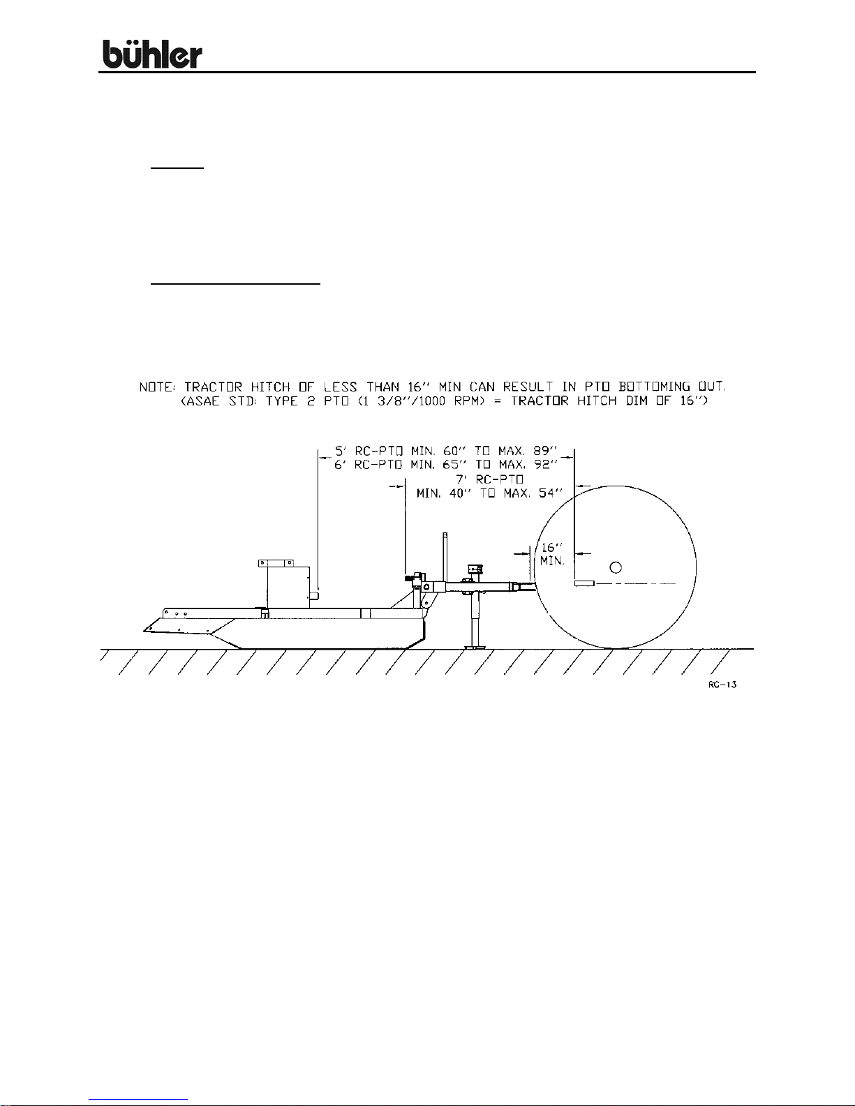
1. Connecting to tractor: All cutters are supplied with a standard 1 3/8" 6-spline
yoke on the PTO shaft.
Warning: This cutter is designed to operate only with a 540 rpm PTO. After
connecting cutter to tractor and before doing any cutting, check to see that the
PTO shaft is not touching anywhere on the cutter when raising and lowering or
when cornering.
2.
3.
PTO Shafts: Make sure the length of the PTO shaft is compatible with different
working positions of the cutter. Carefully follow the lubrication chart supplied with
the PTO shaft. When cutting, avoid joint angles over 35º. PTO shafts should be
disengaged when turning sharp corners. Using tape or a bright colored marking
pen, mark on the outer shields the position where the shaft is completely pushed
together and the position where you have a 4" overlap. Watch these marks when
moving the cutter through all possible operating angles to see that the PTO shaft
stays within this range.
PTO shafts with shear pin - Loosen the outer shield on the implement end of the
PTO and push the gearbox shaft through the end yoke. Using snap ring pliers,
put the snap ring on the end of the gearbox shaft. This is what keeps the PTO
shaft on if the shear pin breaks and the cutter should
Insert a ½” x 3 ½”
shields.
PTO shafts with slip clutch - Note: All PTO shafts with a slip clutch are shipped
with the slip clutch disengaged. There are four socket set screws on the inside of
the clutch assembly which are all turned out as far as they go to engage the
clutch. Disengage by turning set screws in fully. The clutch should slip if a hard
object such as a stump or rock is hit by the blades.
Caution: Always be certain that the PTO shaft is disengaged and the tractor
brakes are locked before making this or any other adjustment.
The clutch plates should be "burned" just before using the cutter in spring for the
first time. This is done by disengaging the clutch and then engaging the PTO
shaft for a few seconds till the clutch plates smoke. After this you engage the
clutch again as described above. This is done because the plates may lock up
during prolonged storage.
Operating tractor engine: Operate the tractor PTO at 540 rpm when doing
normal cutting. If the forward speed is too high, a lower gear can be used.
Grade 2 bolt with a lock nut to act as shear pin and replace all
not be used without it.
6
Rotary Cutter
OPERATING INSTRUCTIONS – cont’d.
4.
to harvest.
5.
Cutting: The cutter should be run with the front end a little low or just level for
normal light cutting. For brush or dense tall weeds, running front end high may
give a better shredding job. On rough ground, the front end will also tend to dig
in less. The cutter can also be used to shred stubble or top vegetables prior
5’ & 6’ Trailing Models: The wheels supplied with the cutter are for towing at
speeds of no more than 20 miles per hour. These wheels should be greased
every time you use the cutter.
7

Rotary Cutter
SERVICING INSTRUCTIONS
LUBRICATION
1.
Gearbox: The gearbox should be filled with SAE90 oil to the bottom edge of the
lower oil plug when shipped. Check this before using the cutter and at regular
intervals to see that this oil level is maintained.
2. Grease wheels, tail wheel spindle sleeve, universal joints and shield bushings on
the PTO shaft after every eight hours of use. Lubricate the telescoping PTO tube
and the PTO quick release about every twenty hours of use.
3.
4.
5.
Shielding: Always keep all shielding in place and repair or replace if damaged.
Blades: When replacing or grinding the cutting blades, both blades must be
replaced or reground at the same time to maintain the proper balance in the
cutting unit.
IMPORTANT: Use Buhler replacement blades only. Using substitute blades
may be dangerous. When changing blades, open the access door on the deck
and take the screws out of the blade pin clips. The clips are then pulled out and
the blade should fall down. Replacing the new or sharpened blades is done with
the back of the mower raised and securely blocked so it will not fall. Bolt on the
blade pin clips and close the access door.
PTO Shaft: To replace clutch lining on slip clutch PTO shafts, first disengage the
clutch by turning the four set screws all the way in. Remove outside bolts from
clutch assembly and replace clutch linings. When re-tightening bolts, stop when
the clutch spacer starts to touch the clutch plates. You should be able to just
move the spacer by hand when you have the correct bolt torque. Re-engage
clutch after assembly is complete.
8

Rotary Cutter
ASSEMBLY INSTRUCTIONS
Three point hitch mounted models:
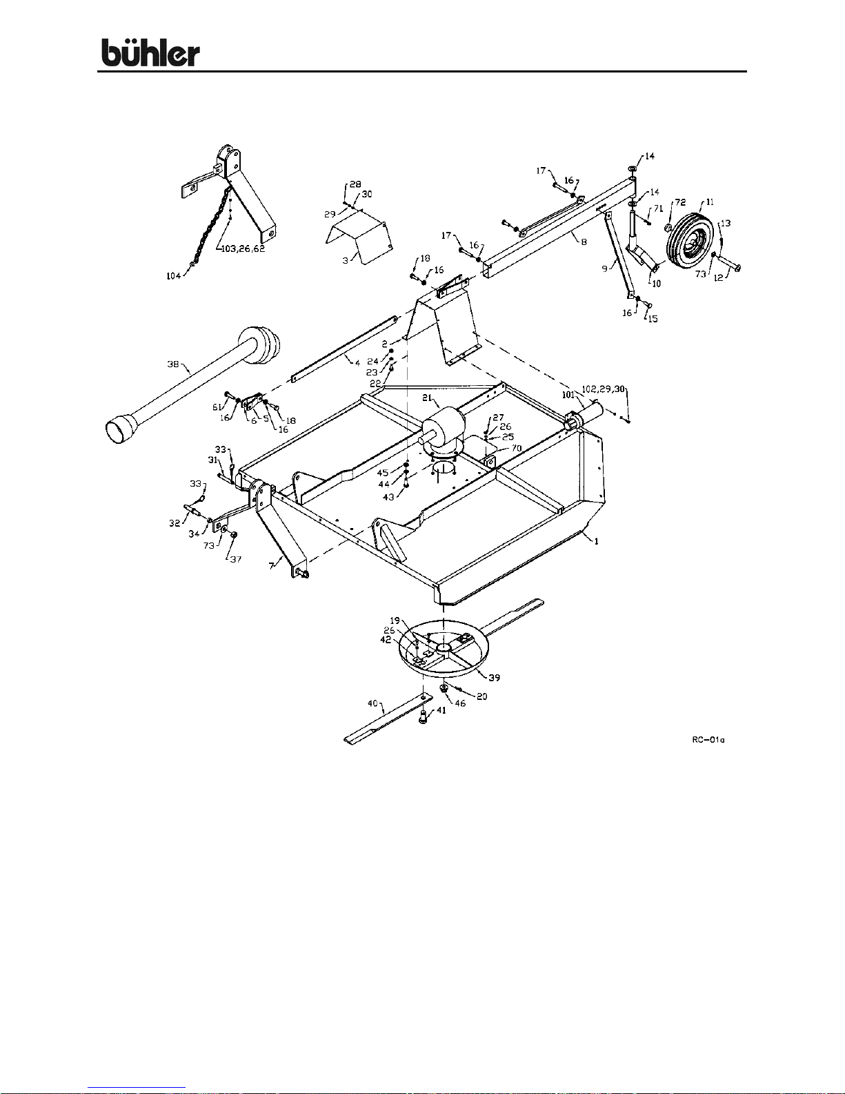
1. Mount the hitch assembly (#7) to the deck using the category 1 lift arm pins (#32)
supplied. The bushings (#34), and the 1" I.D. washer (#73) should allow the
hitch to swivel freely.
2. The ends of the two pivot arms (#5 & #6) with the offset holes bolt to the hitch
using a 5/8" x 4" bolt and lock nut. The offset should be turned down. The lift
arm (#4) bolts between the ends of the pivot arms and the brackets at the top of
the center mount (#2) using 5/8" x 2" hex bolts and lock nuts.
the lock nuts. The entire hitch assembly should swivel freely if properly
assembled. Assemble chain PTO holder (#104) to 3-point hitch (#7) using one
3/8” x 1 ½” hex bolt (#103), lock washer and hex nut.
3. Bolt the tail wheel arm (#8) to the center mount (#2) using a 5/8" x 4" bolt and
lock nut. The tube welded to the outside end of the tail wheel arm is offset
2 ¼” past the edge of the tube. The 2 ¼” offset is turned down for 5’ and 6’
cutters and up for 7’ cutters. Assemble the tail wheel (#11) in the wheel yoke
(#10) using axle pin (#12) and a ¼” x 1 ½” cotter pin. Mount the yoke in the
sleeve at the end of the tail wheel arm. Use an 18 gauge washer on each side of
the sleeve and lock in place with a ¼” x 1 ¾” cotter pin. The adjustment arms
(#9) hold the tail wheel arm in place and also set the cutting height of the cutter.
Bolt arms to the deck using hex bolts (#15) and lock nuts and to the tail-wheel
arm using 5/8" x 4" hex bolt and lock nut.
4. Connect the PTO shaft to the gearbox. A snap ring holds on the PTO shafts with
a shear pin. The clutch must be engaged on PTO shafts with a slip clutch as per
operating instructions so the clutch will slip if you hit a hard object. After
engaging clutch, bolt the PTO guard (#3) to the center mount using 5/16" x ¾”
hex bolts, lock washers and hex nuts.
5. Re-check all the fasteners. There should be free movement of all pieces held
together by a bolt and lock nut.
Do not over tighten
9

Rotary Cutter
ASSEMBLY INSTRUCTIONS
Trailing Models:
1. Mount the swivel tube assembly (#47) to the cutter deck by bolting to the
edge of the deck reinforcement using ½” x 1 ¾” hex bolts, lock washers and hex
nuts.
2. The wheel yoke arms (#48) may be assembled to cutter in two ways:
a) Wheels trailing behind mower. Assemble as shown in drawing. Bolt the
yoke arms (#48) to the tube assembly using ½” x 2" hex bolts, lock
washers and hex nuts with the wheels turned to the inside of the mower.
With the wheels in this position, the control rod clevis (#53) attaches to
the top bracket on the tube assembly as shown in drawing. Use a 1" I.D.
flat washer and a ¼” x 1 ½” cotter pin to mount the wheels.
b) Wheels forward at side of cutter. Bolt the yoke arms to the tube assembly
so the wheels are on the outside of the cutter. With the wheels in this
position, the control rod clevis (#53) attaches to the bottom bracket on the
tube assembly.
3. Bolt the tongue assembly (#63) to the cutter deck using 7/8" x 2 ½” bolts, lock
washers and hex nuts. The 1 ¼” diameter x 5/8" long bushings (#58) held in
place by a 1" I.D. flat washer (#73) should allow the tongue to swivel.
4. An 8" stroke hydraulic cylinder (#49) is required to operate the hydraulic lift on
the cutter. Using ½” x 90º elbows (#50) on the hydraulic cylinder will keep the
hoses in better alignment (for 5’ & 6’). Approximately 12 foot long hydraulic
hoses are required.
5. Bolt the welded end of the level control rod (#56) to the front tongue as shown on
drawing using a 5/8" x 2 ½” hex bolt and lock nut. The control rod clevis (#53)
must be adjusted so the cutter will sit level with the ground when it is pinned to
the swivel assembly.
Note: Be sure to use the top bracket on the swivel assembly (#47) when the
wheels are trailing behind the cutter as shown in drawing.
6. Mount the slip clutch PTO shaft on the cutter. The clutch must be engaged so it
will slip when you hit a hard object as per operating instructions. After engaging
the clutch, bolt on the PTO guard (#3) using 5/16" x ¾” hex bolts, lock washers
and hex nuts.
7. An optional jack (#67) is available to lift the tongue when mounting the cutter on
a tractor.
outside
10

Rotary Cutter
ASSEMBLY INSTRUCTIONS - CONT'D.
Trailing Models:
8. Re-check and tighten all bolts. Only pieces held by a bolt and lock nut should
have free movement.
9.
7’ Cutters Only: Bolt the PTO bearing stand (#76) to the edge of the deck using
5/8” x 1 ¾” hex bolts, lock washers and hex nut. Mount the PTO Q-shaft on the
cutter gearbox. Slide a 1 3/8” pillow bearing onto the shaft at the end of the Qshaft. With the guard mount (#77) under the pillow bearing, bolt the pillow block
to the stand using 5/8” x 2 ¼” hex bolts, lock washers and hex nuts. Connect the
second PTO shaft to the splined end of the Q-shaft. Bolt the PTO guard (#78) to
the stand using ¼” x ½” hex bolts, lock washers and hex nuts.
11
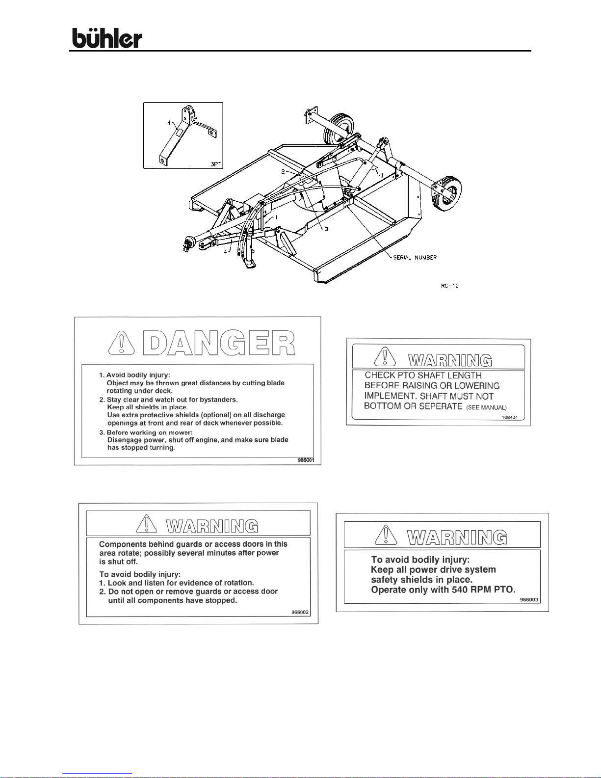
Rotary Cutter
ROTARY CUTTER – THREE POINT HITCH MOUNTED
12
 Loading...