

Page 1

740, 840 & 840G Snowblowers
TABLE OF CONTENTS
DESCRIPTION PAGE
Warranty................................................................................1
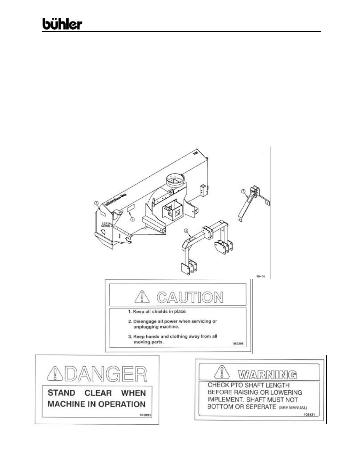
Safety Instructions & Safety Sign Locations......................2
Operating Instructions..........................................................3
Assembly Instructions ..........................................................5
Refilling #840G Gearbox.....................................................8
Snowblower Drawings.........................................................9
Snowblower Parts List.........................................................13
840G Gearbox Drawing & Parts List.................................16
Snowblower PTO Drawing..................................................17
PTO Parts Lists....................................................................18
Cylinder Assembly Drawings & Parts Lists.......................20
Shipping Bundles.................................................................21
Page 2

740, 840 & 840G Snowblowers
WARRANTY REGISTRATION AND POLICY
Buhler Manufacturing products are warranted for a period of twelve (12) months from
original date of purchase, by original purchaser, to be free from defects in material and
workmanship under correct, normal agricultural use and proper applications.
Buhler Manufacturing’s obligations under this warranty shall be limited to the repair or
exchange, at Buhler Manufacturing’s option, of any Buhler Manufacturing product or
part which proves to be defective as provided. Buhler Manufacturing reserves the right
to either inspect the product at the buyer’s location or have it returned to the factory for
inspection.
The above warranty does not extend to goods damaged or subject to accident, abuse or
misuse after shipment from Buhler Manufacturing’s factory, nor to goods altered or
repaired by anyone other than an authorized Buhler Manufacturing representative.
Buhler Manufacturing makes no Express Warranties other than those, which are
specifically described. Any description of goods, including any references and
specifications in catalogues, circulars and other written material published, is for the
sole purpose of identifying goods and shall conform to such descriptions. Any sample
or model is for illustrative purposes only and does not create an Express Warranty that
the goods conform to sample or model shown.
The purchaser is solely responsible for determining suitability of goods sold. This
warranty is expressly in lieu of all other warranties expressed or implied. Buhler
Manufacturing will in no event be liable for any incidental or consequential damages
whatsoever. Nor for any sum in excess of the price received for the goods for which
liability is claimed.
WARRANTY CLAIMS:
Warranty requests must be prepared on Buhler Manufacturing Warranty Claim Forms
with all requested information properly completed. Warranty Claims must be submitted
within a thirty (30) day period from date of failure repair.
WARRANTY LABOR:
Any labor subject to warranty must be authorized by Buhler Manufacturing. The labor
rate for replacing defective parts, where applicable, will be credited at a rate determined
by the Company, Buhler Manufacturing.
IMPORTANT FACTS:
Buckets and Bucket Tines Carry No Warranty
Bent Spears Carry No Warranty
Snowblower Fan Shafts Carry No Warranty
Mower Blades Carry No Warranty
Portable Auger Parts Have Two (2) Year Warranty
- 1 -
Page 3
740, 840 & 840G Snowblowers
SNOWBLOWER
This manual is for model #740 & #840 snowblowers with an open gear gearbox and for
model #840G snowblower, which has a sealed oil bath gearbox. When ordering parts,
specify model number and serial number. The snowblower is the push type and will
mount to a tractor with a 540 rpm PTO. It is supplied with category 1 pins and also
bushings, which convert the pins to a category 2. A category 1 quick hitch fits on all
three sizes. A category 2 quick hitch also fits #840 and #840G models. This 84" wide
snowblower comes with a hydraulic chute control as standard equipment. A hand crank
chute control is available. There is a shear bolt on the auger and on the PTO shaft to
protect the machine from damage if a large object is picked up. Any smaller objects in
the snow will be thrown with it and could cause serious injury. Do not let anyone stand
behind the tractor in the area of the discharged snow.
#1
#1
#2
#2 #3
- 2 -
Page 4

740, 840 & 840G Snowblowers
OPERATING INSTRUCTIONS
1. Do not operate the blower in the fully raised position. The three-point
hitch on some tractors raises high enough to cause the PTO shaft to bind.
This can cause damage to the PTO shaft and/or to the hitch and pins.
NOTE: PTO shaft angle should not exceed 20 degrees for
optimum performance and life. Damage may occur to PTO and/or
Snowblower if angle becomes more extreme.
2. Depth of cut can be partially controlled by tilting the blower forward or
backward. Adjust the top link of the tractor hitch so the snowblower is just
slightly tilted back when resting on the ground. Caution: Excessive
backward tilt may cause the "U” joints to flutter resulting in PTO shear bolt
failure.
3. Adjust the lower link sway chains or blocks on the tractor to restrict side
movement of the blower when operating.
4. Run the blower at low rpm to check operation before blowing snow.
5. The snowblower has two shear bolts to protect the tractor and blower in
case a large object enters the blower. PTO shear bolt (Two 5/16" x
1"-Grade 5) Auger shear bolt (1/4" x 1"-Grade 5). Shear bolts should be
fastened with a lock nut or two jam nuts. These bolts must be kept tight to
prevent wear of the bolt and bolt holes.
6. Never run PTO shaft at over 600 rpm.
7. Chain tension: Slack on the lower side of the chain should be 3/8 to 1/2
inch.
8. Lubrication:
a) The spout clamps and rings should be periodically lubricated with
gun grease.
b) PTO shaft universal joints and square shaft slide should be greased
daily.
c) Regularly oiling the chain will significantly increase the life of the
chain.
d) The grease fitting on the hydraulic spout swivel arm should be kept
lubricated.
e) For #740 & #840 only: Gearbox is open type and need not be
greased or lubricated.
For #840G only: See Section on refilling for correct oil level. Use
any 80-90 gear oil or multigrade with 80 minimum.
- 3 -
Page 5

740, 840 & 840G Snowblowers
OPERATING INSTRUCTIONS – cont’d.
9. Periodically check all bolts for tightness. The bolt holding on the fan and
the bearing bolts are of particular importance.
10. Danger: Always stop blower for servicing or unplugging. The PTO
should be disengaged before dismounting from the tractor.
11. CAUTION: Always check to see that both ends of the PTO shaft
are securely attached as per instructions every time you are preparing to
use the snowblower.
12. Shear Sprocket: The Shear Sprocket (#52) should be checked at the
beginning of every season to make sure it will spin freely. With time this
sprocket could corrode and seize which will not allow the shear bolt to
break if something jams in the snowblower auger. Clean to loosen if
necessary.
13. When replacing bearings or tightening a loose bearing collar, always
tighten collar in the direction of shaft rotation using a center punch or a
similar tool.
- 4 -
Page 6

740, 840 & 840G Snowblowers
ASSEMBLY INSTRUCTIONS
1. #740: Turn the bottom tube weldments (#9) as shown in drawing and slide them
into the sleeve welded to the main body.
#840 & #840G: Turn the bottom tubes (#93) as shown in drawing and slide them
into the sleeve welded to the main body.
ALL SIZES: The correct position for each individual tractor will be determined
when mounting the snowblower on the tractor. These tubes are connected to the
tractor with a ¾” x 4 ¼” pin (#96) and a hair pin clip (#104).
2. #740: Bolt the left (#20) and the right (#21) a-frames to the inside of the
plates welded to the hitch tubes using 7/8” x 2 ½” hex bolts (#102) and
lock nuts. Join the top of the hitch arms by bolting a 1” o.d. x 2” spacer
(#100) between the top plates using a ¾” x 4” bolt, lock washer and hex
nut through the lower outside holes. Bolt the upper hitch tube weldment
(#47) between the same plates using the same size of bolt. Use the
inside holes on the top plates for the upper tube. The other end of the top
hitch tube bolts between the welded brackets on the top edge of the fan
housing with the same hardware. Tube must be turned as shown in
drawing. Tighten all hardware.
#840 & #840G: Turn the hitch weldment (#4) as shown in drawing. Bolt
the hitch to the two bottom tubes (#93) using 7/8” x 5” bolts (#103) and
lock nuts. The upper hitch tube (#80) bolts to the top of the hitch and the
welded brackets on the top edge of the fan housing using ¾” x 4” bolts
(#97), lock washers and hex nuts. Tube must be turned as shown in
drawing. Tighten all hardware.
3. #740: A category 1 top link pin (#18) is fitted in the top holes of the hitch
arm plates. This pin is used for standard three-point hitch only. The
bushing in the lower holes is used for the quick hitch.
#840 & #840G: The hitch fits standard category 1 and 2 three-point
hitches as well as category 1 and 2 quick hitches. The highest and lowest
holes are for standard three-point only. The inside set of holes must be
used for a quick hitch. Adaptor bushings are supplied to convert from
category 1 or 2.
4. Mount the discharge spout (#6) using the spout clamps (#59) bolted to the
spout ring on the snowblower. Lubricate the spout ring and clamps.
- 5 -
Page 7

740, 840 & 840G Snowblowers
ASSEMBLY INSTRUCTIONS – cont’d.
5. Hydraulic spout swivel:
a) Mount the swivel arm (#60) onto the swivel pin welded to the back
corner of the fan housing using a 1" I.D. washer (#29) and a 3/16" x
1 ½” cotter pin (#62).
b) Wrap cable (#61) around spout and clamp to the ends of the swivel using
3/16" cable clamps (#17).
c) With the swivel in extended position (i.e. cylinder fully extended) and the
spout turned to the right, clamp the cable to the spout cable anchor using
a ¼” cable clamp (#84). Ensure that the spout is not jammed and that
there is no slack in the cable.
d) Use a standard 8" stroke cylinder (20 ¼” min., 28 ¼” max. pin centers).
e) Note: A hydraulic cylinder and hose kit to control the spout deflector is
available as an option.
6. Hand Crank (Option):
a) Fasten hand crank assembly (#5) using two ½” x 1 ¼” hex bolts, lock
washers and hex nuts.
b) Thread cable (#7) through hole in hand crank to even lengths and wrap
around the tube to each side of the hole four turns in opposite directions.
c) Turn spout to center forward position and clamp cable to cable anchor on
far side of spout using clamp (#84).
7. Mounting blower on tractor:
a) Mount the blower on a tractor with a category 1 or category 2 hitch.
b) Using tape or bright colored marking pen, mark on the outer shields the
position where the shaft is completely pushed together and the position
where you have a 4" overlap. Watch these marks when moving the
blower through all possible operating angles to see that the PTO shaft
stays within this range.
c) With the engine on the tractor shut off, attach the PTO shaft. The tractor
end has a standard 6-spline end with a spring loaded locking collar. The
Snowblower end has a clamp-style yoke with a 3/8" keyway. Slide the
yoke onto the gearbox shaft with the 3/8" key supplied. Lock the yoke in
place with the ½” x 3" hex bolt and lock nut fitted through the groove in the
gearbox shaft. After tightening the bolt, insert and tighten the 3/8" socket
set screw supplied. CAUTION : Always check to see that both
ends of the PTO shaft are securely attached every time the Snowblower is
used. This should always be done with the Tractor engine off.
d) Check that the PTO shaft does not bottom or separate with the blower in
the extreme high and low positions. A longer optional PTO shaft is
available if the standard shaft is too short. Check for free movement of all
parts in various raised positions; particularly the PTO shaft .
- 6 -
Page 8

740, 840 & 840G Snowblowers
ASSEMBLY INSTRUCTIONS – cont’d.
8. PTO Shield: All snowblowers are supplied with a PTO shield. Bolt the
shield (#74) to the hinges on the top of the gearbox on both the #740 and
#840 snowblowers using ¼” x ½” hex bolts, lock washers and hex nuts.
Insert a 3/16" cotter pin in the hole in the shield and in the hole at the
bottom corner of the gearbox. Fold back the cotter pins to hold them in
place. Hook the ends of the spring (#71) into these cotter pins to hold the
shield down. To mount the shield (#74) on the #840G snowblower,
remove the two rear bolts at the top of the gearbox (#63). Bolt the PTO
shield to the gearbox plate using these same bolts. Insert a 3/16" cotter
pin in the hole in the shield and fold to lock in place. Hook one end of the
spring (#71) into this cotter pin and the other end into a hole in the lower
gearbox plate to hold the shield in place. CAUTION: Do not run the
snowblower without this shield in place.
- 7 -
Page 9

740, 840 & 840G Snowblowers
REFILLING GEARBOX WITH OIL: #840G ONLY
If the gearbox requires refilling with oil because of repairs to the gearbox,
add oil to the level shown in the drawing. Check the level regularly using
the plug in the lid. The correct level is even with the bottom of the plug.
- 8 -
Page 10

740, 840 & 840G Snowblowers
740 & 840 SNOWBLOWERS
- 9 -
Page 11

740, 840 & 840G Snowblowers
- 10 -
Page 12

740, 840 & 840G Snowblowers
#840G SNOWBLOWER
- 11 -
Page 13

740, 840 & 840G Snowblowers
- 12 -
Page 14

740, 840 & 840G Snowblowers
WHEN ORDERING PARTS
Always give your dealer the Model, Color and Serial Number of your machine to assist
him in ordering and obtaining the correct parts. Use the exploded view and tabular
listing of the area of interest to exactly identify the required part.
#740, #840, & #840G SNOWBLOWERS
ITEM PART # DESCRIPTION
1 907241 Main Body (#740)
907235 Main Body (#840)
907240 Main Body (#840G)
2 907244 Stand Weld't - 8'' Tall
3 965294 Stand Pin Weld't 9/16'' x 2 7/8''
4 F0463 Hitch Weld't (Cat. 1 & 2)
5 965803 Hand Crank
6 965653 Discharge Spout
7 965927 3/16'' Cable x 100'' Long
8 F842 PTO Shaft (Standard)
F844 PTO Shaft (Optional Long)
9 907213 Btm Tube Weld't 20 5/8'' Lg
10 81676 5/8'' Hex Nut (pl)
11 81677 5/8'' Lock Washer (pl)
12 81620 1/2'' x 1 1/4'' Hex Bolt (pl)
13 81636 1/2'' Hex Nut (pl)
14 81637 1/2'' Lock Washer (pl)
15 81627 1/2'' x 3'' Hex Bolt (pl)
16 965821 3/8'' x 1 3/4'' Key
17 965806 3/16'' Cable Clamp
18 965807 Top Link Pin (Cat.1)
19 965808 Top Link Pin Bushing (Cat.1-2)
20 907214 A-Frame - LH (Cat. 1)
21 907215 A-Frame - RH (Cat. 1)
22 965911 7/16'' Linch Pin
23 84277 1/2'' x 1 1/2'' Hex Bolt (pl)
24 84072 3/8'' x 3/4'' Hex Bolt (pl)
25 81593 3/8'' Lock Washer (pl)
26 81592 3/8'' Hex Nut (pl)
27 81638 1/2'' B.S. Flat Washer (pl)
28 812026 5/16'' x 1'' Hex Bolt (pl)
29 967140 1'' x 10Ga Narrow Rim Washer (pl)
30 902377 Fan Key - 3/8'' x 4 3/4''
965814 3/8'' x 4 1/4'' Key (#840G Only)
31 965835 Fan Shaft, 1 1/2'' x 16 3/4''
- 13 -
Page 15

740, 840 & 840G Snowblowers
32 965816
33 965817 Bevel Gear - 1 1/2'' Bore
34 965818 1 1/4'' Bearing w/ Collar
35 961637 Bearing Retainer (Set)
36 86170 3/8'' x 1'' Hex Bolt (pl)
37 901940 5/16'' x 1 1/4'' Key (#740 & #840)
38 965413 Drive Shaft (#740), 1 1/4'' x 37 1/4''
965402 Drive Shaft (#840), 1 1/4'' x 42 1/4''
965403 Drive Shaft (#840G), 1 1/4'' x 34''
39 936402 PTO Safety Chain
40 81527 1/4'' x 1'' Hex Bolt (pl)
41 84498 1/4'' Lock Nut (pl)
42 968627 1 1/2'' Bearing With Collar
43 967260 1 1/2'' Bearing Retainer (Set)
44 965822 Fan (Standard 3-Blade)
965447 Fan (Optional 4-Blade)
45 965414 Auger (#740)
965405 Auger (#840 & #840G)
46 965415 Drive Shaft Guard (#740)
965404 Drive Shaft Guard (#840 & #840G)
47 907218 Hitch Tube Weld't 22''Lg
48 965834 Idler Spacer, 5/8'' Long
49 84111 1/2'' x 1 1/4'' Sq. Hd. Set Screw (pl)
50 984077 1/2'' Jam Nut (pl)
51 965825 40 Tooth Sprocket, #50
52 965826 13 Tooth Sprocket, #50 (Shear)
53 965827 Roller Chain (#50 x 98 Link w/ Conn)
54 965844 15 Tooth Idler Sprocket, #50
55 86171 3/8'' x 1 1/4'' Hex Bolt (pl)
56 965917 1 3/8'' Bearing With Collar
57 961675 Bearing Retainer (Set)
58 84289 5/8'' x 3'' Hex Bolt (pl)
59 965416 Spout Clamp
60 907820 Swivel Arm
61 965832 3/16'' x 62'' Cable
62 9812433 3/16'' x 1 1/2'' Cotter Pin (pl)
63 BU50506 Gearbox w/o Oil (#840G)
64 907674 7/8'' Lock Nut
65 967164 Pound-In Grease Nipple
66 81619 1/2'' x 1'' Hex Bolt (pl)
67 81549 5/16'' x 3/4'' Hex Bolt (pl)
68 81569 5/16'' Lock Washer (pl)
69 81568 5/16'' Hex Nut (pl)
70 965968 Idler Shield
Bevel Gear - 1 1/4'' Bore
- 14 -
Page 16

740, 840 & 840G Snowblowers
71 960135
72 9812432 3/16'' x 1 1/4'' Cotter Pin (pl)
73 900712 Skid Pin Weldment
74 965409 PTO Shield (#840G)
965410 PTO Shield (#740 & #840)
75 81523 1/4'' x 1/2'' Hex Bolt (pl)
76 81545 1/4'' Lock Washer (pl)
77 81544 1/4'' Hex Nut (pl)
78 812364 1/2'' Lock Nut (pl)
79 988999 3/8'' x 3/8'' Socket Set Screw
80 907221 Upper Hitch Tube Weld't 21'' Lg (Cat 1 & 2)
81 965646 Spout Adjustment Bar
82 903523 1/2'' x 1 1/2'' Adjustment Pin Weldment
83 961012 #16 Hair Pin Clip
84 961658 1/4'' Cable Clamp
85 961876 1/2'' x 1 1/2'' Clevis Pin (pl)
86 902407 Skid Plate Weldment
87 9812487 1 1/4'' x 10ga Narrow Rim Washer (pl)
88 967110 1 1/4'' x 14ga Narrow Rim Washer (pl)
89 9812439 1 1/4'' x 18ga Narrow Rim Washer (pl)
90 967135 1 1/ 2'' x 10ga Narrow Rim Washer (pl)
91 9812444 1 1/2'' x 14ga Narrow Rim Washer (pl)
92 9812443 1 1/2'' x 18ga Narrow Rim Washer (pl)
93 907250 Hitch Inner Tube 20 5/8" Lg (Cat 1 & 2)
94 907315 Pin 7/8" x 7 3/4" (Cat 1 & 2)
95 907316 Pin Sleeve 1 1/8'' x 2 7/8''Lg (Cat 1 & 2)
96 905821 Pin Rod 3/4'' x 4 1/4'' Lg
97 84336 3/4'' x 4'' Hex Bolt (pl)
98 81701 3/4'' Lock Washer (pl)
99 81700 3/4'' Hex Nut (pl)
100 965808 Sleeve 1'' OD x 2'' Lg
101 967361 Pin 7/8'' x 4'' Lg
102 966527 7/8'' x 2 1/2'' Lg Hex Bolt
103 811826 7/8'' x 5'' Hex Bolt
104 12779 #9 Hair Pin Clip
- 15 -
PTO Shield Spring
Page 17

740, 840 & 840G Snowblowers
840G SNOWBLOWER GEARBOX
MODEL #840 G SNOWBLOWER GEARBOX PARTS LIST
Item # Part # Description
BU50506 Gearbox Complete
1 BU50310 Gearbox Casting Only
2 BU500089-3 Pipe Plug
3 BU50457 Gearbox Cover
4 BU500167-1 Relief Valve
5 BU50458 Gearbox Gasket
6 BU50508 Cross Shaft
7 BU50502 Pinion Shaft
8 BU50329 Bevel Gear - 1 1/2'' Bore
9 BU50331 Bevel Gear - 1 3/8'' Bore
10 BU50428 Staking Lock Nut
11 BU50444 Staking Lock Nut
12 BU50422-1 Oil Seal (3 Used)
13 BU50415 Retainer Ring (4 Used)
14 BU575902 Bearing Cup (2 Used)
15 BU575901 Bearing Cone (2 Used)
16 BU50429 Key
17 BU50210X Shim Set
18 BU575907 Bearing Cup (2 Used)
19 BU575906 Bearing Cone (2 Used)
20 BU278811 Retainer Ring
21 BU50417-1 Key
- 16 -
Page 18

740, 840 & 840G Snowblowers
#740, #840, #840G SNOWBLOWER PTO
- 17 -
Page 19

740, 840 & 840G Snowblowers
SNOWBLOWER PTO (STANDARD)
Item # Part # Description
F842 Shaft Complete
936263 Tractor Half of PTO (Shear)
936264 Implement Half of PTO (Clamp Yoke)
1 936277 Shear Assembly
2 936199 Safety Slide Lock Repair Kit
(Collar, Spring, Ret. Ring, 2-Pawls)
3 936249 Shear Assembly Repair Kit (3/8'' x 1/2'' Bolt,
Lube, Blank, 31 - 1/4'' Balls)
*4 903296 Shear Bolt - 5/16" x 1" (Grade 5) (Pack of 10)
903297 Shear Bolt - 5/16" x 1" (Grade 8) (Pack of 10)
5 812362 5/16'' Lock Nut
6 936025 Repair Kit (Std)
906504 Extended Life Repair Kit (Option)
7 936270 Yoke & Tube
8 936319 Bearing & Sn ap Ring Kit
9 936272 Inner Shield
10 936273 Outer Shield
11 936274 Yoke & Shaft
12 936269 Clamp Yoke
13 81627 1/2'' x 3'' Hex Bolt (pl)
14 812364 1/2'' Lock Nut (pl)
* For Higher RPM Use 5/16'' x 1'' Gr. 8 Shear Shank Bolt, Supplied In Bag Of Hardware
- 18 -
Page 20

740, 840 & 840G Snowblowers
SNOWBLOWER PTO (OPTIONAL LONG)
Item # Part # Description
F844 Shaft Complete
936285 Tractor Half of PTO (Shear)
936280 Implement Half of PTO (Clamp Yoke)
1 936277 Shear Assembly
2 936199 Safety Slide Lock Repair Kit
(Collar, Spring, Ret. Ring, 2-Pawls)
3 936249 Shear Assembly Repair Kit
(3/8'' x 1/2'' Bolt, Lube, Blank, 31-1/4'' Balls)
*4 903296 Shear Bolt - 5/16" x 1" (Grade 5) (Pack of 10)
903297 Shear Bolt - 5/16" x 1" (Grade 8) (Pack of 10)
5 812362 5/16'' Lock Nut
6 936025 Repair Kit (Std)
906504 Extended Life Repair Kit (Option)
7 936281 Yoke & Tube
8 936319 Bearing & Snap Ring Kit
9 936282 Inner Shield
10 936283 Outer Shield
11 936284 Yoke & Shaft
12 936269 Clamp Yoke
13 81627 1/2'' x 3'' Hex Bolt (pl)
14 812364 1/2'' Lock Nut (pl)
* For Higher RPM Use 5/16'' x 1'' Gr. 8 Shear Shank Bolt, Supplied In Bag Of Hardware
- 19 -
Page 21

740, 840 & 840G Snowblowers
1.75 X 5 CYLINDER ASSEMBLY
Item # Part # Description
24930 Cyl Complete
1 115367 Tube Weldt
2 112104 Shaft Weldt 1.0 Dia
3 X2669 Seal Kit
3.5 x 8 CYLINDER ASSEMBLY
Item # Part # Description
24803 Cyl Complete
1 24804 Tube Weldt
2 113934 Piston Rod 1.5 Dia
3 X2098 Seal Kit
- 20 -
Page 22

740, 840 & 840G Snowblowers
740, 840 & 840G FARM KING SNOWBLOWER BUNDLES
QUANTITY BUNDLE NO. DESCRIPTION
#740 Snowblower w/hydraulic chute control, 3-blade fan – Y740
1 F0458 Body Assembly
1 F0463 Hitch
#740 Snowblower w/hydraulic chute cont rol, 4-blade fan – Y740-4
1 F0459 Body Assembly
1 F0463 Hitch
#840 Snowblower w/hydraulic chute control, 3-blade fan – Y840
1 F0454 Body Assembly
1 F0463 Hitch
#840 Snowblower w/hydraulic chute control, 4-blade fan – Y840-4
1 F0455 Body Assembly
1 F0463 Hitch
#840G Snowblower w/hydraulic chute control, 4-blade fan – Y840G
1 F0456 Body Assembly
1 F0463 Hitch
#840G Snowblower w/hydraulic chute control, 4-blade fan – Y840G-4
1 F0457 Body Assembly
1 F0463 Hitch
OPTIONS AVAILABLE
F844 – 36” Optional long PTO
F842 – Standard PTO
F9102 – Hand Crank Kit
F9106 – Hydraulic Chute Control Kit
F9116 – Hydraulic Cylinder & Hose Kit for Spout Swivel
F9117 – Spout Deflector Cylinder & Hose Kit
- 21 -
 Loading...