

Page 1

500 & 600 Snowblower
TABLE OF CONTENTS
DESCRIPTION PAGE
Warranty......................................................................1
Safety Instructions & Safety Sign Locations ................2
Operating Instructions..................................................3
Assembly Instructions..................................................5
500 & 600 Snowblower Drawings................................8
500 & 600 Snowblower Parts List................................10
500 & 600 Snowblower PTO Drawing..........................13
500 & 600 Snowblower PTO Parts Lists......................14
Cylinder Assembly Drawings & Parts Lists..................15
Shipping Bundles.........................................................16
Page 2

500 & 600 Snowblower
WARRANTY REGISTRATION AND POLICY
Buhler Manufacturing products are warranted for a period of twelve (12) months from
original date of purchase, by original purchaser, to be free from defects in material and
workmanship under correct, normal agricultural use and proper applications.
Buhler Manufacturing’s obligations under this warranty shall be limited to the repair or
exchange, at Buhler Manufacturing’s option, of any Buhler Manufacturing product or
part which proves to be defective as provided. Buhler Manufacturing reserves the right
to either inspect the product at the buyer’s location or have it returned to the factory for
inspection.
The above warranty does not extend to goods damaged or subject to accident, abuse or
misuse after shipment from Buhler Manufacturing’s factory, nor to goods altered or
repaired by anyone other than an authorized Buhler Manufacturing representative.
Buhler Manufacturing makes no Express Warranties other than those, which are
specifically described. Any description of goods, including any references and
specifications in catalogues, circulars and other written material published, is for the
sole purpose of identifying goods and shall conform to such descriptions. Any sample
or model is for illustrative purposes only and does not create an Express Warranty that
the goods conform to sample or model shown.
The purchaser is solely responsible for determining suitability of goods sold. This
warranty is expressly in lieu of all other warranties expressed or implied. Buhler
Manufacturing will in no event be liable for any incidental or consequential damages
whatsoever. Nor for any sum in excess of the price received for the goods for which
liability is claimed.
WARRANTY CLAIMS:
Warranty requests must be prepared on Buhler Manufacturing Warranty Claim Forms
with all requested information properly completed. Warranty Claims must be submitted
within a thirty (30) day period from date of failure repair.
WARRANTY LABOR:
Any labor subject to warranty must be authorized by Buhler Manufacturing. The labor
rate for replacing defective parts, where applicable, will be credited at a rate determined
by the Company, Buhler Manufacturing.
IMPORTANT FACTS:
Buckets and Bucket Tines Carry No Warranty
Bent Spears Carry No Warranty
Snowblower Fan Shafts Carry No Warranty
Mower Blades Carry No Warranty
Portable Auger Parts Have Two (2) Year Warranty
- 1 -
Page 3
500 & 600 Snowblower
SNOWBLOWER
This manual is for both models #500 and #600 snowblowers. When ordering parts,
specify model number and serial number. Both snowblowers are the push type and will
mount to a tractor with a category 1 three-point hitch or a category 1 Quick Hitch and
540 rpm PTO. The #500 has a 50" cutting width while the #600 has a 60" cutting width.
Both snowblowers come with a hand crank chute control as standard. A hydraulic
control is available as an option at extra cost. There is a shear bolt on the auger and on
the PTO shaft to protect the machine from damage if a large object is picked up. Any
smaller objects in the snow will be thrown with it and could cause serious injury. Do not
let anyone stand behind the tractor in the area of the discharged snow.
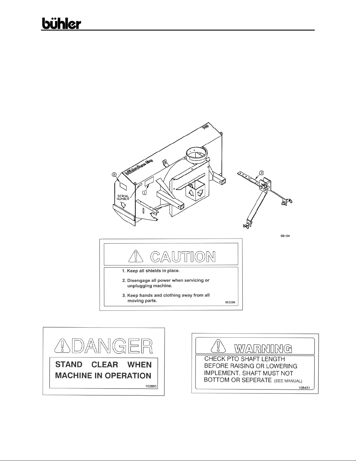
#1
#2 #3
- 2 -
Page 4

500 & 600 Snowblower
OPERATING INSTRUCTIONS
1. Do not operate the blower in the fully raised position. The threepoint hitch on some tractors raises high enough to cause the PTO
shaft to bind. This can cause damage to the PTO shaft and/or to
the hitch and pins.
NOTE: PTO shaft angle should not exceed 20° for optimum
performance and life. Damage may occur to PTO and/or
snowblower if angle becomes more extreme.
2. Depth of cut can be partially controlled by tilting the blower forward
or backward. Adjust the top link of the tractor hitch so the
snowblower is just slightly tilted back when resting on the ground.
ALERT: Excessive backward tilt may cause the “U” joints to flutter
resulting in PTO shear bolt failure.
3. Adjust the lower link sway chains or blocks on the tractor to restrict
side movement of the blower when operating.
4. Run the blower at low rpm to check operation before blowing snow.
5. The snowblower has two shear bolts to protect the tractor and
blower in case a large object enters the blower. PTO shear bolts #500 - one 3/8" x 1" (gr.8), #600 - two 5/16" x 1" (gr. 8), auger
shear bolt – ¼” x 1" (gr.2). Shear bolts should be fastened with a
lock nut or two jam nuts. These bolts must be kept tight to prevent
wear of the bolt and bolt holes.
6. Never run PTO shaft at over 600 rpm.
7. Chain Tension: Slack on the lower side of the chain should be 3/8 to ½”
8. Lubrication:
a) The spout clamps and rings should be periodically lubricated
with gun grease.
b) PTO shaft universal joints and square shaft slide should be
greased daily.
c) PTO shear yoke should be greased before using the blower
for the first time.
d) Regularly oiling the chain will significantly increase the life of
the chain.
e) Gearbox is open type and need not be greased or lubricated.
f) Hydraulic spout option – grease the swivel arm.
- 3 -
Page 5

500 & 600 Snowblower
OPERATING INSTRUCTIONS – cont’d.
9. Periodically check all bolts for tightness. The bolt holding on the
fan and the bearing bolts are of particular importance.
10. Danger: Always stop blower for servicing or unplugging.
The PTO should be disengaged before dismounting from the tractor.
11. Caution: Always check to see that both ends of the PTO shaft are
securely attached as per instructions every time you are preparing to use
the snowblower.
12. When replacing bearings or tightening a loose bearing collar, always
tighten collar in the direction of shaft rotation using a center punch or a
similar tool.
13. Shear Sprocket: The shear sprocket (#43) should be checked at the
beginning of every season to make sure it will spin freely. With time the
sprocket plate could corrode and seize which will not allow the shear bolt
to break if something jams in the snowblower auger. Clean to loosen if
necessary.
- 4 -
Page 6

500 & 600 Snowblower
#500 AND #600 SNOWBLOWER ASSEMBLY INSTRUCTIONS
1. Mount the discharge spout (#2) using the spout clamp (#3) bolted to the
spout ring on the snowblower. Lubricate the spout ring and clamp.
NOTE: A hydraulic cylinder and hose kit to control the spout deflector is
available as an option.
2. Hitch Assembly: With right and left hitch tubes (#5 & #6) turned as
shown in drawing, slide them into the sleeve welded to the main body.
These tubes are adjustable to four different positions. The correct position
for each individual tractor will be determined when mounting the
snowblower on the tractor. These tubes are connected to the
snowblower with a ¾” x 3 ¼” pin (#11) and a hair pin clip (#12). Bolt the
left (#84) and the right (#85) hitch arms to the outside of the clevises on
the hitch tubes using the lift pins (#9). NOTE: Pins should be turned to
the outside. Do not tighten any hardware until assembly is complete. Join
the top of the hitch arms by bolting a 1” O.D. x 2 ¼” spacer (#4) between
the top plates using a ¾” x 4” bolt and lock nut through the lower outside
holes. Bolt the hitch top bar (#86) between the same plates using the
same bolt through the welded tube on the bar. Use the inside holes on the
top plates for the top bar. The other end of the hitch top bar bolts to the
top of the blower fan housing with a ½” x 1 ¾” hex bolt, lock washer and
hex nut. Use the same hole position as the hitch tubes. Tighten all
hardware.
A category 1 top link pin (#8) is fitted in the top holes of the hitch arm
plates. This pin is used for standard three-point hitch only. The bushing
in the lower holes is used for the Quick Hitch.
3. Hand Crank Assembly: (Standard)
a) Bolt the crank mounting bracket (#16) to the top of the hitch using
3/8" x 1 ¼” hex bolts, lock washers and hex nuts.
b) Insert the crank tube (#15) through the mount and through the
bracket welded to the main housing. Lock the crank in place using
a washer and roll pin on each side of the bracket.
c) Thread the cable (#17) through the hole in the crank tube to even
lengths and wrap around the tube to each side of the hole four
turns in opposite directions.
d) With the spout turned forward, fasten the cable to the bracket
welded to the bottom of the spout using a ¼” cable clamp (#70).
- 5 -
Page 7

500 & 600 Snowblower
500 & 600 SNOWBLOWER ASSEMBLY INSTRUCTIONS – cont’d.
4. Hydraulic Control Assembly: (Option)
a) Bolt the hydraulic swivel assembly (#21) to the back of the fan
housing on the left side using ½” x 1 ¼” hex bolts, lock washers
and hex nuts.
b) Bolt the cylinder mounting bracket (#23) to the back of the fan
housing on the right side using the same size hex bolts.
c) Turn the spout forward and the center of the swivel arm in line with
the spout center. With the spout and swivel arm in this position,
wrap the cable (#22) around the spout and clamp to both ends of
the swivel arm and to the bracket welded to the bottom of the
spout using 3/16" cable clamps (#20).
d) Use a standard 8" stroke cylinder (20 ¼” min., 28 ¼” max. pin
centers).
5. Mounting Blower on Tractor:
a) Mount the blower on a tractor with a category 1 hitch.
b) Using tape or a bright colored marking pen, mark on the outer
shield the position where the shaft is completely pushed together
and the position where you have a 4" overlap. Watch these marks
when moving the blower through all possible operating angles to
see that the PTO shaft stays within this range.
c) With the engine on the tractor shut off, attach the PTO shaft. The
tractor end has a standard 6-spline end with a spring loaded locking
collar. The snowblower end has a clamp-style yoke with a ¼” key
way. Slide the yoke onto the gearbox shaft with the ¼” key
supplied. Lock the yoke in place with the ½” x 3" hex
bolt and lock nut fitted through the groove in the gearbox shaft.
After tightening the bolt, insert and tighten the 3/8" socket set screw
supplied. Caution: Always check to see that both ends of the
PTO shaft are securely attached every time the snowblower is
used. This should always be done with the tractor engine off.
d) Check that the PTO shaft does not bottom or separate with the
blower in the extreme high and low positions. Check to see which
of the four different hitch positions will allow you to keep about a 4"
minimum overlap on the PTO shields without bottoming out. This
position varies between different tractor models because of the
different lengths of the three-point arms. If the PTO shaft is still too
long with the hitch fully extended, the PTO shaft will have to be cut
shorter. Check for free movement of all parts in various raised
positions, particularly the PTO shaft.
- 6 -
Page 8

500 & 600 Snowblower
500 & 600 SNOWBLOWER ASSEMBLY INSTRUCTIONS – cont’d.
6. PTO Shield:
All snowblowers manufactured for the 1990 production and up are
supplied with a PTO shield. The PTO shield (#65) bolts to the gearbox
assembly using ¼” x ¾” hex bolts. Hook one end of the spring (#66) in
the hole in the back edge of the PTO shield and the other end of the
spring in the hole punched in the edge of the gearbox assembly.
CAUTION: Do not run the snowblower without the PTO shield in
place.
- 7 -
Page 9

500 & 600 Snowblower
- 8 -
Page 10

500 & 600 Snowblower
- 9 -
Page 11

500 & 600 Snowblower
WHEN ORDERING PARTS
Always give your dealer the Model, Color and Serial Number of your machine to assist
him in ordering and obtaining the correct parts. Use the exploded view and tabular
listing of the area of interest to exactly identify the required part.
500 & 600 SNOWBLOWERS
ITEM PART # DESCRIPTION
1 905595 Main Body (#500)
905596 Main Body (#600)
2 965645 Discharge Spout
3 965638 Spout Clamp
4 906770 Hitch Spacer 1''OD x 2 1/4''
5 907127 Hitch Tube Weldt - R
6 907128 Hitch Tube Weldt - L
7 F512 PTO Shaft (#500)
F612 PTO Shaft (#600)
8 965807 Top Link Pin (Cat. 1)
9 965809 Lift Pin W/ Nut And Washer (Cat.1)
10 965911 7/16'' Linch Pin
11 965624 Hitch Pin 3/4'' x 3 1/4''
12 12779 #9 Hair Pin Clip (pl)
13 968811 Pto Key - 1/4'' x 2''
14 988999 3/8''Dia. x 3/8'' Socket Set Screw
15 906667 Crank Handle
16 965634 Crank Mounting Bracket
17 965616 Crank Cable - 3/16'' x 84'' Long
18 9812438 1'' ID x 14 Ga Narrow Rim Washer (pl)
19 9812425 1/4'' x 1 1/4'' Spring Pin
20 965806 3/16'' Cable Clamp
21 965626 Hydraulic Swivel Weldment
22 965627 Hydraulic Cable - 3/16'' x 58''
23 965628 Cylinder Mounting Bracket
24 965512 Drive Shaft Guard (#500)
965644 Drive Shaft Guard (#600)
25 965818 1 1/4'' Bearing W/ Collar
26 961637 1 1/4'' Bearing Retainer
27 86171 3/8'' x 1 1/4'' Hex Bolt (pl)
28 81593 3/8'' Lock Washer (pl)
29 81592 3/8'' Hex Nut (pl)
30 86170 3/8'' x 1'' Hex Bolt (pl)
31 81620 1/2'' x 1 1/4'' Hex Bolt (pl)
32 81637 1/2'' Lock Washer (pl)
33 81636 1/2'' Hex Nut (pl)
- 10 -
Page 12

500 & 600 Snowblower
34
35 81549 5/16'' x 3/4'' Hex Bolt (pl)
36 81569 5/16'' Lock Washer (pl)
37 81568 5/16'' Hex Nut (pl)
38 965630 Fan (#500) (Standard 3-Blade)
39 965505 Auger (#500)
40 965637 40 Tooth Sprocket - #500 & #600
41 965631 Roller Chain (#50 x 94 Link w/ Conn)
42 965844 Idler Sprocket, 15T, #50
43 965826 Shear Sprocket, 13T, #50
44 965507 Drive Shaft (#500), 1 1/4'' x 25 1/2''
45 965632 Idler Spacer - 1/2'' Long
46 965069 Fan Shaft 1 1/4'' x 14 1/2''
47 961882 Bevel Gear, 1 1/4'' Bore
48 961676 1 1/4'' Bearing W/ Collar
49 961675 1 1/4'' Bearing Retainer
50 901331 Fan Key - 1/4'' x 3 1/2''
51 109343 3/16'' x 1 1/8'' Woodruff Key
52 84335 5/8'' x 2 1/2'' Hex Bolt (pl)
53 81678 5/8'' Flat Washer BS (pl)
54 81677 5/8'' Lock Washer (pl)
55 81676 5/8'' Hex Nut (pl)
56 812216 1/4'' x 1'' Hex Bolt (pl) (Gr. 2)
57 84498 1/4'' Lock Nut (pl)
58 81598 7/16'' x 1 1/4'' Hex Bolt (pl)
59 81615 7/16'' Lock Washer (pl)
60 981616 7/16'' Flat Washer BS (pl)
61 81213 3/8'' x 1'' Sq. Hd. Set Screw (pl)
62 81627 1/2'' x 3'' Hex Bolt (pl)
63 812364 1/2'' Lock Nut (pl)
64 965968 Idler Shield
65 965643 Gearbox Lid
66 960135 Pto Guard Spring
67 81525 1/4'' x 3/4'' Hex Bolt (pl)
68 81545 1/4'' Lock Washer (pl)
69 81544 1/4'' Hex Nut (pl)
70 961658 1/4'' Cable Clamp
71 9812434 1/4'' x 1 1/2'' Cotter Pin (pl)
72 965646 Spout Adjustment Bar
73 903523 1/2'' x 1 1/2'' Adjustment Pin Weldment
87553 1/2'' x 1 3/4'' Hex Bolt (pl)
965445 Fan (#500) (4-Blade)
965642 Fan (#600) (Standard 3-Blade)
907118 Fan (#600) (4-Blade)
965610 Auger (#600)
965613 Drive Shaft (#600), 1 1/4'' x 30 1/2''
- 11 -
Page 13

500 & 600 Snowblower
74
75 961876 1/2'' x 1 1/2'' Clevis Pin (pl)
76 901435 1/2'' x 2 1/2'' Clevis Pin (pl)
77 902477 Skid Plate Weldt
78 812026 5/16'' x 1'' Hex Bolt (pl)
79 9812426 1/4'' x 1 3/4'' Spring Pin (pl)
80 936402 PTO Safety Chain
81 9812487 Narrow Rim Washer 1 1/4'' x 10ga (pl)
82 967110 Narrow Rim Washer 1 1/4'' x 14ga (pl)
83 9812439 Narrow Rim Washer 1 1/4'' x 18ga (pl)
84 907133 Hitch Arm Weldt - L
85 907134 Hitch Arm Weldt - R
86 907138 Hitch Top Bar Weldt (#500)
87 84336 3/4'' x 4'' Hex Bolt (pl)
88 812365 3/4'' Lock Nut (pl)
- 12 -
961012 #16 Hair Pin Clip
907139 Hitch Top Bar Weldt (#600)
Page 14

500 & 600 Snowblower
#500 & #600 SNOWBLOWER PTO SHAFT
- 13 -
Page 15

500 & 600 Snowblower
500 Farm King Snowblower PTO Parts List
Item # Part # Description
F512 Shaft Complete
936379 Tractor Half of PTO (shear)
936380 Implement Half of PTO (clamp yoke)
1 936247 Shear Assembly
2 936168 Spring - Lock Kit (Collar, Spring, Ret. Ring, 2-3/8'' Balls)
3 936248 Shear Kit (3/8" x 1/2" Bolt, Blank, 24-1/4" Balls
4 Shear Bolt 3/8" x 1" (grade 8) - 1 required
5 812363 3/8" Lock Nut
6 936079 Repair Kit
7 936381 Yoke & Tube
8 936389 Bearing & Snap Ring Kit
9 936382 Inner Guard
10 936383 Outer Guard
11 936384 Yoke & Shaft
12 936254 Clamp Yoke
13 81627 1/2" x 3" Hex Bolt (pl)
14 812364 1/2" Lock Nut (pl)
600 Farm King Snowblower PTO Parts List
Item # Part # Description
F612 Shaft Complete
936385 Tractor Half of PTO (shear)
936386 Implement Half of PTO (clamp yoke)
1 936257 Shear Assembly
2 936168 Spring - Lock Kit (Collar, Spring, Ret. Ring, 2-3/8'' Balls)
3 936248 Shear Kit
*4 Shear Bolt 5/16" x 1" (grade 8) - 2 required
5 812362 5/16" Lock Nut
6 936093 Repair Kit
7 936375 Yoke & Tube
8 936319 Bearing & Snap Ring Kit
9 936391 Inner Guard
10 936377 Outer Guard
11 936378 Yoke & Shaft
12 936262 Clamp Yoke
13 81627 1/2" x 3" Hex Bolt (pl)
14 812364 1/2" Lock Nut (pl)
* For higher RPM use 5/16'' x 1'' (Gr. 8) Shear shank bolt - supplied in the bag of hardware
- 14 -
Page 16

500 & 600 Snowblower
1.75 X 5 CYLINDER ASSEMBLY
Item # Part # Description
24930 Cyl Complete
1 115367 Tube Weldt
2 112104 Shaft Weldt 1.0 Dia
3 X2669 Seal Kit
- 15 -
Page 17

500 & 600 Snowblower
500 & 600 FARM KING SNOWBLOWER BUNDLES
QUANTITY BUNDLE NO. DESCRIPTION
#500 Snowblower w/Hand Crank, 3-Blade Fan – Y500
1 F0430 Body Assembly
#600 Snowblower w/Hand Crank, 3-Blade Fan – Y600
1 F0434 Body Assembly
#500 Snowblower w/Hand Crank, 4-Blade Fan – Y500-4
1 F0431 Body Assembly
#600 Snowblower w/Hand Crank, 4-Blade Fan – Y600-4
1 F0435 Body Assembly
OPTIONS AVAILABLE:
F9304 Hydraulic Chute control for #500 & #600 Snowblower
(less cylinder)
FX9305 Hand crank for #500 & #600 Snowblower
F512 #500 Snowblower PTO
F612 #600 Snowblower PTO
F9117 Deflector Cylinder & Hose Kit for #500 & #600
F620 Optional Long PTO for #500 & #600
- 16 -
 Loading...