

Page 1
Installation and Operation Instructions
Sample gas cooler
EGK 10
BE450005 ◦ 05/2015
Original instructions
Page 2

Bühler Technologies GmbH, Harkortstr. 29, D-40880 Ratingen
Tel. +49 (0) 21 02 / 49 89-0, Fax: +49 (0) 21 02 / 49 89-20
Internet: www.buehler-technologies.com
E-Mail: analyse@buehler-technologies.com
Read this instruction carefully prior to installation and/or use.
Pay attention particularly to all advises and safety instructions
to prevent injuries. Bühler Technologies can not be held responsible for misusing the product or unreliable function due to
unauthorised modifications.
All rights reserved. Bühler Technologies GmbH 2015
Document information
Document No. ....................................BE450005
Version .................................................. 05/2015
Page 3

Installation and Operation Instructions
Sample gas cooler EGK 10
Contents
Contents
1 Introduction.......................................................................................................................................................... 2
1.1 Intended Use .................................................................................................................................................2
1.2 Types .............................................................................................................................................................2
1.3 Scope of delivery ...........................................................................................................................................2
2 Safety instructions ..............................................................................................................................................3
2.1 Important advice ............................................................................................................................................3
2.2 General hazard warnings...............................................................................................................................4
3 Transport and storage ........................................................................................................................................5
4 Installation and connection ................................................................................................................................ 6
4.1 Installation site requirements .........................................................................................................................6
4.2 Installation......................................................................................................................................................6
4.3 Electrical connections ....................................................................................................................................7
5 Operation and control ......................................................................................................................................... 8
5.1 Operation of the menu functions....................................................................................................................8
5.1.1 Overview of the menu items .............................................................................................................. 9
5.1.2 Detailed description of the operational principle ................................................................................9
5.2 Description of the menu functions ...............................................................................................................10
5.2.1 Main menu .......................................................................................................................................10
5.2.2 Submenu.......................................................................................................................................... 10
6 Maintenance.......................................................................................................................................................11
7 Service und repair .............................................................................................................................................12
7.1 Troubleshooting ...........................................................................................................................................12
7.2 Safety instructions .......................................................................................................................................13
7.3 Opening the housing....................................................................................................................................13
7.4 Replacing the fuse of the cooler ..................................................................................................................15
7.5 Replacing the fan.........................................................................................................................................15
7.6 Replacing the power supply board ..............................................................................................................16
7.7 Replacing the controller board MCP1..........................................................................................................17
7.8 Replacing the display...................................................................................................................................17
7.9 Cleaning and removal of the heat exchanger ..............................................................................................17
7.10 Replacing the fuse of the peristaltic pump (option - only housing version)..................................................18
7.11 Replacing the hoses of the peristaltic pump (option)...................................................................................18
7.12 Spare parts and accessories .......................................................................................................................18
8 Disposal.............................................................................................................................................................. 19
9 Attached documents ......................................................................................................................................... 20
DE450007 EGK10...............................................................................................................................................21
KX450001_EGK1_EGK1-2_EGK4S_EGK10.....................................................................................................25
Declaration of Contamination status...............................................................................................................26
iBE45000505/2015
Page 4

Installation and Operation Instructions
Sample gas cooler EGK 10
Introduction
1 Introduction
1.1 Intended Use
This unit is intended for industrial use in gas analysis systems. It's an essential component for
conditioning the sample gas to protect the analysis instrument from residual moisture in the
sample gas.
Please note the specifications in the data sheets on the specific intended use, existing material
combinations, as well as pressure- and temperature limits.
1.2 Types
The device is delivered with different configurations. The part number given on the type plate informs you about the specific configuration of your device.
1.3 Scope of delivery
– Cooler
– Product documentation (brief instruction + CD)
– Connection-/mounting accessories (optional)
2 BE450005 05/2015
Page 5
Installation and Operation Instructions
Sample gas cooler EGK 10
Safety instructions
2 Safety instructions
2.1 Important advice
Operation of the device is only valid if:
– the product is used under the conditions described in the installation- and operation instruc-
tion, the intended application according to the type plate and the intended use. In case of unauthorized modifications done by the user Bühler Technologies GmbH can not be held re-
sponsible for any damage,
– when complying with the specifications and markings on the nameplates.
– the performance limits given in the datasheets and in the installation- and operation instruc-
tion are obeyed,
– monitoring devices and safety devices are installed properly,
– service and repair is carried out by Bühler Technologies GmbH,
– only original spare parts are used.
This manual is part of the equipment. The manufacturer keeps the right to modify specifications
without advanced notice. Keep this manual for later use.
Signal words for warnings
DANGER
Signal word for an imminent danger with high risk, resulting in severe injuries
or death if not avoided.
WARNING
Signal word for a hazardous situation with medium risk, possibly resulting in
severe injuries or death if not avoided.
CAUTION
Signal word for a hazardous situation with low risk, resulting in damaged to
the device or the property or minor or medium injuries if not avoided.
NOTICE
Signal word for important information to the product.
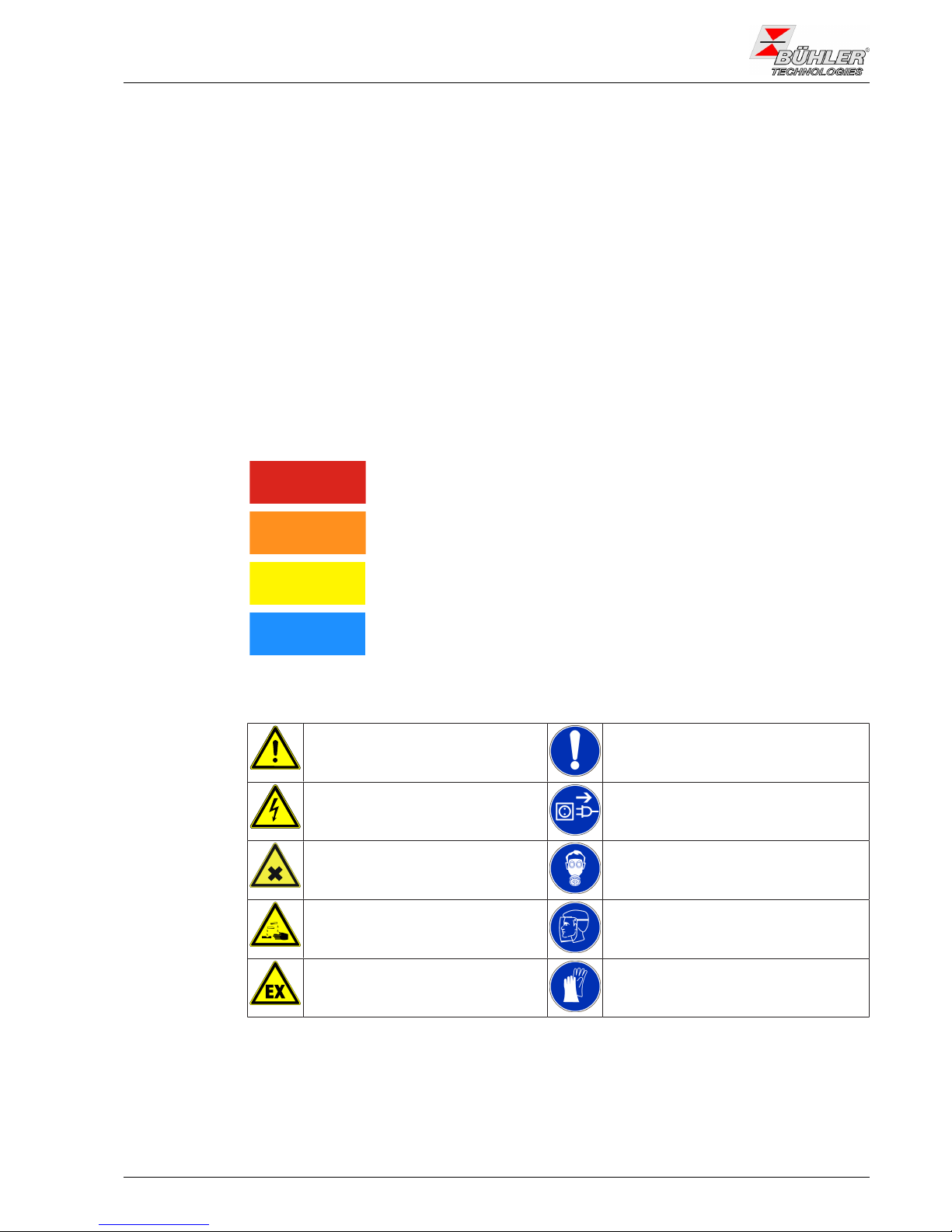
Warning signs
These instructions use the following warning signs:
Warns of a general hazard General notice
Warns of voltage Unplug from mains
Warns not to inhale toxic gasses Wear respiratory equipment
Warns of corrosive liquids Wear a safety mask
Warns of explosive areas Wear gloves
3BE45000505/2015
Page 6
Installation and Operation Instructions
Sample gas cooler EGK 10
Safety instructions
2.2 General hazard warnings
Installation of the device shall be performed by trained staff only, familiar with the safety requirements and risks.
Check all relevant safety regulations and technical indications for the specific installation place.
Prevent failures and protect persons against injuries and the device against damage.
The operator of the system must secure that:
– safety and operation instructions are accessible and followed,
– local safety regulations and standards are obeyed,
– performance data and installation specifications are regarded,
– safety devices are installed and recommended maintenance is performed,
– national regulations for disposal of electrical equipment are obeyed.
Maintenance, repair:
– Repairs on the device must be carried out by Bühler authorized persons only.
– Only perform modifications, maintenance or mounting described in this manual.
– Only use original spare parts.
When carrying out maintenance works of any kind, the relevant health and safety regulations of
the country of use must be observed.
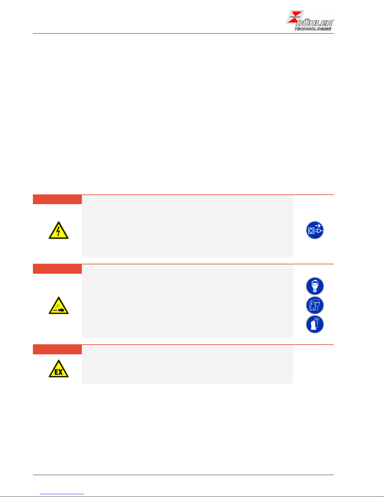
DANGER Electrical voltage
Electrocution hazard.
a) Disconnect the device from power supply.
b) Make sure that the equipment cannot be reconnected to mains unintention-
ally.
c) The device must be opened by trained staff only.
d) Regard correct mains voltage.
DANGER Toxic and corrosive gases / condensate
Sample gas / condensate can be hazardous.
a) Take care that the gas is exhausted in a place where no persons are in
danger.
b) Before maintenance turn off the gas supply and make sure that it cannot be
turned on unintentionally.
c) Protect yourself during maintenance against toxic / corrosive gases / con-
densate. Use gloves, respirator and face protector under certain circumstances.
DANGER Potentially explosive atmosphere
Explosion hazard if used in hazardous areas.
The device is not suitable for operation in hazardous areas with potentially explosive atmospheres.
Do not expose the device to combustible or explosive gas mixtures.
4 BE450005 05/2015
Page 7

Installation and Operation Instructions
Sample gas cooler EGK 10
Transport and storage
3 Transport and storage
The device should be only transported in the original case or in appropriate packing.
If the device is not used for some time, protect it against heat and humidity. Store the device in
a roofed, dry, and dust free room. Temperature should be between -20 °C and 60 °C (-4 °F and
140 °F).
5BE45000505/2015
Page 8
Installation and Operation Instructions
Sample gas cooler EGK 10
Installation and connection
4 Installation and connection
4.1 Installation site requirements
The unit is intended for wall-mounted or table-top use in enclosed areas. Adequate protection
from the weather must be provided when used outdoors.
Install the unit leaving enough room below the cooler to discharge the condensate. Leave room
above for the gas supply.
Be sure to maintain the approved ambient temperature. Do not obstruct the convection of the
cooler. The vents must have enough room to the next obstacle. The distance must especially be
a minimum of 10 cm on the air outlet side.
Ensure adequate ventilation when installing in enclosed housings, e.g. analyser cabinets. If the
convection is inadequate, we recommend aerating the cabinet or installing a fan to lower the inside temperature.
4.2 Installation
Run the gas supply to the cooler with a downward slope. The gas inputs are marked in red and
additionally labelled “IN”.
If a large amount of condensate accumulates, we recommend using a condensate pre-separator before the cooler. Our fluid separators with automatic condensate drain, 11LD spec.,
AK20V or model 165 SS, are suitable.
Glass vessels and automatic condensate drains are available for draining condensate for external mounting below the unit. When using automatic condensate drains, the gas pump must
be installed ahead of the cooler to ensure proper function of the condensate drain.
If the sample gas pump is located at the cooler outlet (suction operation), we recommend using
glass condensate traps or peristaltic pumps.
Connecting the condensate drains
Depending on the material, build a connecting line with fittings and tubing or hose between the
heat exchanger and condensate drain. For stainless steel the condensate drain can be suspended directly to the connecting tube, for hoses the condensate drain must be secured separately
using a clamp.
The condensate drain can be mounted directly to the heat exchanger.
Condensate lines must always be installed with a slope and a minimum inside diameter of DN
8/10 (5/16”).
Peristaltic pump (optional)
A peristaltic pump may also be installed a little away from the cooler. The bottom of the cooler
has two rivet M4 nuts designated for installing the pump directly below the cooler.
NOTICE
Installing peristaltic pumps limits the maximum approved operating pressure
in the system!
Operating pressure ≤ 0.5 bar
6 BE450005 05/2015
Page 9
Installation and Operation Instructions
Sample gas cooler EGK 10
Installation and connection
4.3 Electrical connections
WARNING Hazardous electrical voltage
The device must be installed by trained staff only.
CAUTION Wrong mains voltage
Wrong mains voltage may damage the device.
Regard the correct mains voltage as given on the type plate.
WARNING High voltage
Damage to the device in case of insulation testing
Do not proceed insulation tests with high voltage to the device as a whole!
Insulation test
The device is equipped with extensive EMC protection. If insulation tests are carried out the
electronic filter devices will be damaged. All necessary tests have been carried out for all concerned groups of components at the factory (test voltage 1 kV or 1.5 kV respectively, depending
on the device).
If you wish to carry out the insulation test by yourself, please test only separate groups of components.
Disconnect the compressor, the fan, the heating or the peristaltic pumps, respectively, and then
carry out the insulation tests.
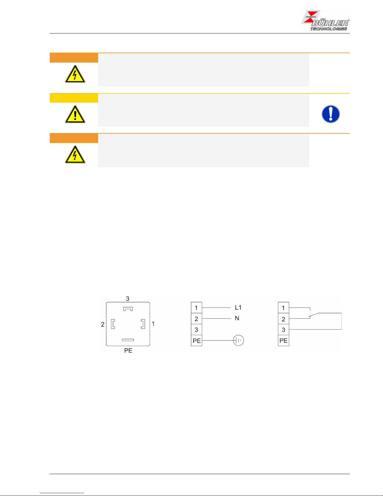
Connection via plug
The device is equipped with connectors according to DIN 43650 for mains and status output. If
the cables are mounted properly, they cannot be interchanged. Please make sure that the connectors are remounted correctly after connecting the cable. The following figures show the pin
assignment with respect to the numbers printed on the connector.
power supply
status outputpin assignment
function ok
alarm
Fig.2: A05-100002 Cooler electric supply
The mains supply must be protected with 16 A. The clamping area has a diameter of 8-10 mm.
If the unit features a peristaltic pump, it must be connected to a power source separately.
7BE45000505/2015
Page 10
Installation and Operation Instructions
Sample gas cooler EGK 10
Operation and control
5 Operation and control
NOTICE
The device must not be operated beyond its specifications.
After turning on the power supply the display shows the actual temperature of the cooling block.
The display blinks until the (set) temperature range with respect to the pre-set output dew point
is reached. The status contact is switched to "Alarm".
If the temperature range is reached, the actual temperature is shown constantly and status contact switches back.
If the display starts blinking during operation or if an error message is displayed see chapter
"Troubleshooting".
For performance limits see datasheet.
5.1 Operation of the menu functions
Overview of the operational principal:
Use this short description if you have experience with the device.
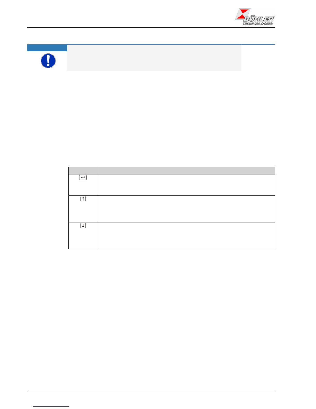
Operation is carried out by only the keys with the following functions:
Key Function
– Switch from measurement display to main menu
– Selection of the display menu item
– Accepting the changed value or selection
– Switch to the upper menu item
– Increase of the value of switching the selection
– Temporary display of the alternative measurement display (if option is in-
stalled)
– Switch to lower menu item
– Decrease of the value of switching the selection
– Temporary display of the alternative measurement display (if option is in-
stalled)
8 BE450005 05/2015
Page 11

Installation and Operation Instructions
Sample gas cooler EGK 10
Operation and control
5.1.1 Overview of the menu items
Displayed is the block temperature with a resolution of 0.5 °C / 0.9 °F. By pressing the Enter button brings the
display to the Main Menu. The unit of temperature is adjustable in the menu Global Settings (Celsius or Fahrenheit).
store value
adjust value
wait 5s: no storage
Set unit Celsius or Fahrenheit
____
____
____
____
____
____
____
____
____
____
____
____
____
____
E1_2
Display of current temperature and operating state
Main Menu
Submenu
Setting range
Display
____
Current temperature
Parameter
Parameter
Temperature
Display
Alarm high
Parameter
Alarm Low
Parameter
Top Settings
Exit
Exit
Cooler display
Set temperature
Alarm hysteresis
Upper alarm
Cooler temperature
Lower alarm
Alarm hysteresis
Exit Submenu
C - F
Global Settings
Exit Main Menu
Adjust the set point:
2°C...20°C / 35.6°F...68°F
Set the upper alarm threshold above
setpoint: tEMP 1°C...7°C / 1.8°F...12.6°F
Set the lower alarm threshold below
setpoint: tEMP -1°C...-3°C / -1.8...-5.4F
tEMP
A Hi
A Lo
E
___
___
____
C
toP
E
5.1.2 Detailed description of the operational principle
The detailed description will guide you through the menu step by step.
Connect the unit to the power supply and wait for the startup procedure to complete. At
first the software version implemented on the unit will be displayed for a brief period.
The unit will then switch directly into measured value display.
Pressing the button will take you from display mode to the main menu. (The control will
continue running whilst in menu mode.)
Use these buttons to navigate the main menu.
After confirming a main menu item the associated submenu will open
Here you can configure operating parameters:
Cycle through the submenu to configure the parameters,
then confirm the menu item to be changed.
You can now set values within specific limits.
After confirming the value the system will save it. This will automatically return you to
the submenu.
If no button is pushed for approx. 5 s, the unit will automatically return to the submenu.
Changes to values will not be saved.
The same applies to the sub- and main menu. The system will automatically return to
display mode without saving the (last) value changed. Parameters which were previously changed and saved will be retained and not reset.
NOTICE!After saving values with the Enter key they will be applied to the control.
E
To exit the main or submenu, select menu item E (Exit).
9BE45000505/2015
Page 12

Installation and Operation Instructions
Sample gas cooler EGK 10
Operation and control
5.2 Description of the menu functions
5.2.1 Main menu
Cooler
This item allows all relevant settings for the cooler. In the corresponding
submenu nominal temperature and alarm limits may be selected.
Globale settings (ToP Settings)
Selection of the global temperature unit, either degree Celsius (C) or degree Fahrenheit (F).
Note: This menu item has no sub-item. The temperature unit is directly selected.
Exit main menu
Selecting this item returns to the display mode.
5.2.2 Submenu
Cooler -> nominal temperature (temperature)
This setting determines the nominal temperature for the cooler temperature. The value can be set to a range from 2 °C (35.6 °F) to 20 °C (68 °F).
Note: The standard value at delivery is 5 °C (41 °F) (unless otherwise agreed). If
the temperature is changed the indicator may blink, until the new operating
range has been reached.
Cooler -> upper alarm limit (alarm high)
Here you can set the upper threshold for the visual signal and the alarm relay. The alarm limit is set to a range from 1 °C (1.8 °F) to 7 °C (12.6 °F) in
relation to the cooler temperature setting.
Note: The standard value at delivery is 3 °C (5.4 °F) (unless otherwise agreed).
Cooler -> lower alarm limit (alarm low)
Here you can set the lower threshold for the visual signal and the alarm relay. The alarm limit is set to a range from -1 °C (-1.8 °F) to -3 °C (-5.4 °F)
in relation to the cooler temperature setting.
Note: The standard value at delivery is -3 °C (-5.4 °F) (unless otherwise agreed).
Exit submenu
Selecting this item returns to the main menu.
10 BE450005 05/2015
Page 13

Installation and Operation Instructions
Sample gas cooler EGK 10
Maintenance
6 Maintenance
If the cooler is delivered in basic configuration, no special maintenance is necessary.
Nevertheless, depending on the configuration different options or accessories may be installed.
In this case, follow the maintenance schedule in regular intervals.
– Option peristaltic pump: Checking the hoses
– Option filter: Checking the filter element
– Option moisture detector: Calibrating the moisture detector
NOTICE!Obey all safety advices and operating rules during any maintenance work.
– Maintenance of the device shall be performed by trained staff only, familiar with the safety re-
quirements and risks.
– Only perform maintenance work described in this manual.
– Regard all relevant safety regulations and internal operating instructions during maintenance.
DANGER Electrical voltage
Electrocution hazard.
a) Disconnect the device from power supply.
b) Make sure that the equipment cannot be reconnected to mains unintention-
ally.
c) The device must be opened by trained staff only.
d) Regard correct mains voltage.
DANGER Toxic and corrosive gases / condensate
Sample gas / condensate can be hazardous.
a) Take care that the gas is exhausted in a place where no persons are in
danger.
b) Before maintenance turn off the gas supply and make sure that it cannot be
turned on unintentionally.
c) Protect yourself during maintenance against toxic / corrosive gases / con-
densate. Use gloves, respirator and face protector under certain circum-
stances.
11BE45000505/2015
Page 14

Installation and Operation Instructions
Sample gas cooler EGK 10
Service und repair
7 Service und repair
If the device shows irregularities see this chapter for troubleshooting.
Repairs on the device must be carried out by Bühler authorized persons only.
If you need help or more information
call: +49-(0)2102-498955 or your local agent
If the device doesn’t work correctly after elimination of failures and turning power on, the device
must be checked by the manufacturer. Please ship the device with suitable packing to
Bühler Technologies GmbH
- Reparatur/Service -
Harkortstraße 29
40880 Ratingen
Deutschland
In Addition, attach the filled in and signed Declaration of Decontamination status to the packing.
Otherwise, your repair order cannot be processed!
The form can be requested by e-mail to service@buehler-technologies.com.
7.1 Troubleshooting
Problem / Failure Possible cause Solution
No display – no power – check power supply
– fuse blown – check fuse and change it if ne-
cessary
Cooler not running – high temperature at the com-
pressor casing
– wait until cooled off and care
for enough ventilation
Status-LED blinks with:
– High temperature – operational temperature not
yet reached
– wait for 20 minutes maximum
– cooling capacity to low, even
though cooler is running
– make sure that air can circu-
late free and that ventilation
louvers are not obstructed
– gas flow / dew point / gas tem-
perature to high
– check application parameters,
install pre-separator
– fan broken – check fan, replace if neces-
sary
– Low temperature – controller defect – send cooler for inspection
Condensate in gas outlet – condensate vessel full – drain vessel
– stuck valve in automatic con-
densate drain
– flush both directions
– cooler overloaded – check limiting parameters
Reduced gas flow – clogged gas path – check / flush heat exchanger
– condensate outlet clogged by
ice
– send cooler for inspection
Display of an error
The display toggles between temperature and error messages.
Error 01 – broken wire – Temperature sensor defect:
send cooler for repair
Error 02 – short circuit – Temperature sensor defect:
send cooler for repair
Tab.2: Troubleshooting
12 BE450005 05/2015
Page 15

Installation and Operation Instructions
Sample gas cooler EGK 10
Service und repair
7.2 Safety instructions
– The device must be operated within its specifications.
– All repairs must be carried out by Bühler authorised personnel only.
– Only perform modifications, servicing or mounting described in this manual.
– Only use original spare parts.
DANGER Electrical voltage
Electrocution hazard.
a) Disconnect the device from power supply.
b) Make sure that the equipment cannot be reconnected to mains unintention-
ally.
c) The device must be opened by trained staff only.
d) Regard correct mains voltage.
DANGER Toxic and corrosive gases / condensate
Sample gas / condensate can be hazardous.
a) Take care that the gas is exhausted in a place where no persons are in
danger.
b) Before maintenance turn off the gas supply and make sure that it cannot be
turned on unintentionally.
c) Protect yourself during maintenance against toxic / corrosive gases / con-
densate. Use gloves, respirator and face protector under certain circum-
stances.
CAUTION Health hazard in case of leaking cooling circuit / heat exchanger
The cooling circuit is filled with coolant R134a.
The heat exchanger is filled with a coolant based on glycol.
In case of leaking / broken cooling circuit / heat exchanger:
a) Avoid contact with skin or eyes.
b) Do not ingest or inhale coolant.
ð Due to the small amount of coolant no health hazards need be feared.
ð Do not put the device back to operation if leakage of the cooling circuit hap-
pend.
7.3 Opening the housing
– Turn off gas supply.
– Switch the device off and disconnect power supply.
– Loosen gas fittings.
– Loosen the screws of the cover.
13BE45000505/2015
Page 16

Installation and Operation Instructions
Sample gas cooler EGK 10
Service und repair
– Lift off the top cover.
– Now all components are accessible.
Fig.4: A100036 EGK 10 Overview
1 Heat exchanger sample gas (filled with
glycol-based coolant)
5 Mains connector
2 Display ABT 400 6 Alarm connector
3 Compressor with closed cooling circuit,
filled with R134a
7 Condenser
4 Electronica with power supply board,
fuse and controller board MCP1
8 Fan
14 BE450005 05/2015
Page 17

Installation and Operation Instructions
Sample gas cooler EGK 10
Service und repair
7.4 Replacing the fuse of the cooler
– Open the device as described in chapter Opening the housing [_page13].
– The fuse is placed on the PBC beneath a plastic cap. Replace the fuse and push down the
plastic cap. Regard the supply voltage for selecting the correct value of the fuse.
Example:
– Fix the cover. Fasten the screws.
– Reconnect hoses.
– Reconnect power supply.
7.5 Replacing the fan
– Open the device as described in chapter Opening the housing [_page13].
– For better accessibility to the fan, remove the electronics. For this, unscrew the screws at the
bottom of the housing and remove the card holder.
– Disconnect the plug at the fan.
– Remove the 2 screws on the left and right side of the fan.
15BE45000505/2015
Page 18

Installation and Operation Instructions
Sample gas cooler EGK 10
Service und repair
– Replace the fan and reassemble the device in reverse order.
7.6 Replacing the power supply board
– Open the device as described in chapter Opening the housing [_page13].
– Remove all cables.
– Terminal diagram EGK:
no jumper set
Heating
Fan
Compressor
Peristaltic pump
Peristaltic pump
Fig.6: A100042 Power supply board
– Unscrew the screws at the corners of the PCB.
– Replace the power supply board and reassemble the device in reverse order.
16 BE450005 05/2015
Page 19

Installation and Operation Instructions
Sample gas cooler EGK 10
Service und repair
7.7 Replacing the controller board MCP1
– Open the device as described in chapter Opening the housing [_page13].
– Pull the controller board MCP1 of the power supply board.
– Insert the new MCP1. Regard the mounting direction: The electronics components must point
upwards!
– Reassemble the device in reverse order.
7.8 Replacing the display
– Open the device as described in chapter Opening the housing [_page13].
– Disconnect the flat ribbon cable from the display.
– Unscrew the 3 nuts and replace the display ABT 400.
– Reassemble the device in reverse order.
7.9 Cleaning and removal of the heat exchanger
Heat exchangers only need to be replaced or maintained when plugged or damaged. If they are
clogged, we recommend checking if using a filter will avoid future occurrences.
– Close the gas supply.
– Switch off the device and unplug from the mains.
– Disconnect the gas connections and condensate drain.
– Pull the heat exchanger up and out.
– Clean the cooling nest (hole inside the cooler block).
– Flush the heat exchanger until all contaminants have been removed.
17BE45000505/2015
Page 20

Installation and Operation Instructions
Sample gas cooler EGK 10
Service und repair
– Grease the cooled outside surface external surface with silicone grease.
– Reinsert the heat exchanger into the cooling nest with a rotating movement.
– Reconnect the gas supply and condensate drain.
– Reconnect to power.
7.10 Replacing the fuse of the peristaltic pump (option - only
housing version)
– Turn off gas supply.
– Switch the device off and disconnect power supply.
– Remove the insulation cover from the fuse holder at the pump’s mounting bracket. For this,
push the cover using a screw driver and quarter-turn it to the left.
– Replace the fuse and refit the insulation cover by quarter-turning it to the right.
– Reconnect power supply.
7.11 Replacing the hoses of the peristaltic pump (option)
– Turn off gas supply.
– Switch the device off and disconnect power supply.
– Remove the supplying and draining hoses from the pump (Take care of the safety instruc-
tions!).
– Loosen the centre knurled screw but do not remove it. Push the screw downwards.
– Pull off the cover.
– Pull the connections sidewards and remove the hose.
– Replace the hose and remount the pump in reverse order.
– Reconnect power supply.
7.12 Spare parts and accessories
Please also specify the model and serial number when ordering parts.
Upgrade and expansion parts can be found in our catalog.
Available spare parts:
Spare part Part no.
Fan 230 V 44 100 31
115 V 44 000 31
Display ABT 400 91 000 10 124
Controller board MCP 1 91 000 10 125
Mains / Controller board 230 V 91 000 10 133
115 V 91 000 10 134
Fuse cooler 230 V / 115 V 5 x 20mm,
800 mA slowblow
91 100 00 001
Fuse peristaltic pump 230 V / 115 V 5 x 20mm,
1A fast-acting
91 100 00 061
Single path heat exchanger TS10 NPT
3/8“
45 100 33
Single path heat exchanger TS10 G3/8“ 45 100 34
Single path heat exchanger, glass coated,
TS10 GB NPT 3/8“
45 100 38
Replacement hose for peristaltic pump
(option), elbow connector
91 240 30 081
Replacement hose for peristaltic pump
(option), straight connector
91 240 30 096
Tab.4: Spare parts and accessories
18 BE450005 05/2015
Page 21

Installation and Operation Instructions
Sample gas cooler EGK 10
Disposal
8 Disposal
The refrigerant circuit of the cooler contains R134a refrigerant. The heat exchanger is charged
with glycol-based coolant.
Dispose of parts so as not to endanger the health or environment. Follow the laws in the country
of use for disposing of electronic components and devices during disposal.
19BE45000505/2015
Page 22

Installation and Operation Instructions
Sample gas cooler EGK 10
Attached documents
9 Attached documents
– Data sheet: DE/DA 45 0007
– Declaration of conformity: KX 45 0001
– Decontamination statement
20 BE450005 05/2015
Page 23

DE 45 0007
02/2012
Page 1/3
Sample Gas Cooler
EGK 10
Accurate measurements of gases require gas samples with § Compact design
stable dew points even under harsh ambient conditions.
§ Easy installation
The EGK 10 is designed for high flow applications.
§ Wall or table mountable
The heart of any cooling system is the cooling block. The
§ Reliable cooling system
EGK 10 gas cooler features a cooling block made of
aluminum which accommodates a highly efficient stainless
§ CFC-free coolant
steel heat exchanger. The temperature of the cooling block is
regulated by the Bühler Constant Regulating System
§ Stainless steel heat exchanger
featuring a straight and constant temperature value.
Maintenance-free model with one gas stream.
§ Nominal capacity 1450 kJ/h
The regulating system provides a display showing the
§ Dew point stability ± 0.2 K
cooling block temperature and a relay-output indicating that
the preset working range is reached.
§ Temperature display for cooling block
The cooler can be supplied with feet adjustable from about
§ Adjustable dew point and alarm
1.5 to 6.6 cm and either mounting brackets or handles.
thresholds
§ Feet, handles or mounting brackets
available
®
Bühler Technologies GmbH
D - 40880 Ratingen, Harkortstr. 29
Tel.: + 49 (0) 2102 / 49 89-0 Fax: + 49 (0) 2102 / 4989-20
Internet: www.buehler-technologies.com
e-mail: analyse@buehler-technologies.com
Page 24

40 °C (7 Vol%)
5...50 °C 3900 3500 3100 2600 2200 70 ml
10...45 °C 3300 3000 2800 2450 2150
5...50 °C 1900 1750 1650 1450 1300
22...35 °C 3000 2800 2650 2350 2100
5...50 °C 1500 1400 1350 1200 1100
22...35 °C 2500 2350 2200 2000 1850
5...50 °C 1200 1100 1040 980 900
22...35 °C - 1800 1750 1600 1450
5...50 °C - 850 820 790 730
22...35 °C - 1350 1280 1200 1150
5...50 °C - 670 650 600 570
22...35 °C - 720 700 650 630
5...50 °C - 360 350 330 320
365 ml
730 ml
50 °C (12 Vol%)
55 °C (16 Vol%)
120 ml
150 ml
200 ml
265 ml
60 °C (20 Vol%)
65 °C (25 Vol%)
70 °C (31 Vol%)
80 °C (47 Vol%)
60 °C 80 °C 100 °C 140 °C 180 °C
Mess- und Regeltechnik GmbH
Vor Öffnen des Gehäuses
Netzstecker ziehen
Danger!Pull mains plug.
Retirer fiche de contact
A000180X
ENTERENTER
300
250
98
470
38
5-65
1
500
518
152,4
177,8
15-40
Technical Data:
Ready for operation After max. 15 minutes
Cooling capacity (at 25°C) 1450 kJ/h
Ambient temperature +5..50°C
Dew point adjustable 2 °C to 20 °C, factory setting 5 °C
Alarm threshold adjustable with respect to dew point
upper alarm threshold +1 °C to +7 °C, factory setting +3 °C
lower alarm threshold -1 °C to -3 °C, factory setting -3 °C
Dew point variations static 0.2 K
Over full operation range ± 2 °C
Power supply 115 or 230 V, 50/60 Hz
Power consumption 750 VA
Cut-in current 12 A at 230 V, 28 A at 115 V
Alarm output 250 VAC/ 150 VDC,
change over contact 2 A, 30 VA
Protection class IP 20
Housing Stainless steel
Weight incl. heat exchanger approx. 32 kg
Max. pressure p 5 bar
max
Pressure drop Dp (v = 1500 l/h) 24 mbar
Example: The ambient can be held in a range of 22...35 °C.
The gas inlet temperature is 140°C and the inlet dew point 60 °C.
In the row “dew point” =60 °C at ambient of 22...35 °C from the column 140 °C results in a value of 2000 l/h. Values
of the gas temperature between the columns can be linearly interpolated.
Flow parameters TS10
The values are given for gas with approx. 1 bar abs.
pressure. The flows are given in l/h at the cooler outlet !
(dead volume 0.86 l)
Dimensions (mm)
Inlet dew point
(moisture)
Ambient
temperature
Flow rate in Nl/h with
gas inlet temperature
Water per h
per 1000l/h
DE 45 0007
02/2012
Page 2/3
Page 25

4
5
6
0 0
9
1
2
0 0 0
1 1 0
1 1 1
1 2 1
0
0
1
2
3
4
5
6
7
441 00 01
441 00 04
441 00 05
441 00 19
912 40 30 106
912 40 30 107
DE 45 0007
02/2012
Page 3/3
We reserve the right to amend specification.
Please indicate with order:
Please extract the part number for the cooler fulfilling your requirements from the type code below.
1)
Peristaltic pumps cannot be mounted to the EGK 10. Peristaltic pumps for separate mounting are available.
Please note: Each gas path should be equipped with a peristaltic pump or an automatic condensate drain.
Art.Nr.
EGK 10
Single path heat exchanger / stainless steel / TS10 G 3/8”
Single path heat exchanger / stainless steel / TS10 NPT 3/8"
Single path heat exchanger / glass coated / TS10 GB NPT 3/8"
Power Supply
115V
230V
Gas Path / Material / Version
Without heat exchanger
1)
Condensate Discharge
Without condensate discharge
Mounting Accessories
Without mounting accessories
With mounting brackets
With feet
With mounting bracktes and feet
With handles
With ounting brackets and handles
With feet and handles
Complete accessory kit
Accessories
Automatic condensate drain 11 LD V 38
Automatic condensate drain AK 20, PVDF
Condensate vessel GL 1; glass, 0,4 l
Condensate vessel GL 2; glass, 1 l
Peristaltic pump, 230 V 50/60 Hz, 1 l/h, for separate mounting
Peristaltic pump, 115 V 50/60 Hz, 1 l/h, for separate mounting
DescriptionPart No.
Page 26

DA 45 0007
02/2012
Page 1/3
Sample gas cooler
EGK 10
Accurate measurements of gases require gas samples with §Compact design
stable dew points even under harsh ambient conditions.
§Easy installation
The EGK 10 is designed for high flow applications.
§Wall or table mountable
The heart of any cooling system is the cooling block. The
§Reliable cooling system
EGK 10 gas cooler features a cooling block made of
aluminum which accommodates a highly efficient stainless
§CFC-free coolant
steel heat exchanger. The temperature of the cooling block is
regulated by the Bühler Constant Regulating System
§Stainless steel heat exchanger
featuring a straight and constant temperature value.
Maintenance-free model with one gas stream.
§Nominal capacity 1450 kJ/h
The regulating system provides a display showing the
§Dew point stability ± 0.2 K
cooling block temperature and a relay-output indicating that
the preset working range is reached.
§Temperature display for cooling block
The cooler can be supplied with feet adjustable from about
§Adjustable dew point and alarm
1.5 to 6.6 cm and either mounting brackets or handles.
thresholds
§Feet, handles or mounting brackets
available
Buhler Technologies LLC
1030 West Hamlin Road, Rochester Hills, MI 48309
Phone: 248.652.1546 Fax: 248.652.1598
Internet: www.buhlertech.com
e-mail: sales@buhlertech.com
Page 27

104 °F(7 Vol%)
-
-
-
-
-
-
122 °F (12 Vol%)
131 °F (16 Vol%)
140 °F (20 Vol%)
149 °F (25 Vol%)
158 °F (31 Vol%)
176 °F (47 Vol%)
140°F176°F
212°F
284°F
356°F
41…122 °F
655852
43372.6 cu. in.
50…113 °F
55
50
47
41
36
41…122 °F
32
2928
2422
72 … 95 °F
50
4744
3935
41…122 °F
25
2323
2018
72 … 95 °F
42
39373331
41…122 °F
2018
17
1615
72 … 95 °F
30
29
2724
41…122 °F
1414
13
12
72 … 95 °F
23
21
2019
41…122 °F
1111
1010
72 … 95 °F
121211
10
41…122 °F
6.05.8
5.5
5.3
13.4 cu. in.
26.7 cu. in.
4.4 cu. in.
5.5 cu. in.
7.3 cu. in.
9.7 cu. in.
Mess- und Regeltechnik GmbH
Vor Öffnen des Gehäuses
Netzstecker ziehen
Danger!Pull mains plug.
Retirer fiche de contact
A000180X
ENTER
1,5”
11,81”
9,84”
3,86”
18,5”
9-2,56”0.5
19,69”
20,39”
6”
7”
0,59-1,57”
Dimensions (in.)
Example:
The ambient can be held in a range of 72 - 95°F. The gas inlet temperature is 284°F and the inlet dew point is
140°F.
In the row dew point =140°F at ambient of 72 - 95°F from the column 284°F results in a value of 33l/min.
Values of gas temperature between the columns can be linearly interpolated.
DA 45 0007
02/2012
Page 2/3
Technical Data:
Ready for operationAfter max. 15 minutes
Cooling capacity (at 77 °F) 1374 Btu/hr
Ambient temperature 40 °F to 120 °F
Dew point adjustable36 °F to 68 °F, factory setting 41 °F
Alarm threshold adjustable with respect to dew point
upper alarm threshold+1.8 °F to +12.6 °F, factory setting +5.4 °F
lower alarm threshold-1.8 °F to -5.4 °F, factory setting -5.4 °F
Dew point variations static0.2 K
Over full operation range± 3.6 °F
Power supply115 V or 230 V, 50/60 Hz
Power consumption750 VA
Cut-in current12 A @ 230 V, 28 A @ 115 V
Alarm output 250 V AC/ 150 V DC,
change over contact2 A, 30 VA
Protection classIP 20
HousingStainless steel
Weight incl. heat exchangerapprox. 70 lb.
Max. pressure p73 psi (5 bar)
max
Pressure drop Dp (v = 1500 l/h)0.35 psi (24 mbar)
Flow parameters TS10
The values are given for gas with approx. 14 psig abs. pressure.
The flows are given in lpm at the cooler outlet ! (dead volume 0.86 l)
Inlet dew point
(moisture)
Ambient
temperature
Flow rate in lpm with
gas inlet temperature
Water per h
per 10 lpm
Page 28

4
5
6
00
9
1
2
000
110
111
121
0
0
1
2
3
4
5
6
7
441 00 01
441 00 04
441 00 05
441 00 19
912 40 30 106
912 40 30 107
Please indicate with order:
Please extract the part number for the cooler fulfilling your requirements from the type code below.
1)
Peristaltic pumps cannot be mounted to the EGK 10. Peristaltic pumps for separate mounting are available.
Please note: Each gas path should be equipped with a peristaltic pump or an automatic condensate drain.
Part.No.
EGK 10
Single path heat exchanger / stainless steel / TS10 G 3/8”
Single path heat exchanger / stainless steel / TS10 NPT 3/8"
Single path heat exchanger / glass coated / TS10 GB NPT 3/8"
Power Supply
115V
230V
Gas Path / Material / Version
Without heat exchanger
1)
Condensate Discharge
Without condensate discharge
Mounting Accessories
Without mounting accessories
With mounting brackets
With feet
With mounting bracktes and feet
With handles
With ounting brackets and handles
With feet and handles
Complete accessory kit
DA 45 0007
02/2012
Page 3/3
Accessories
Automatic condensate drain 11 LD V 38
Automatic condensate drain AK 20, PVDF
Condensate vessel GL 1; glass, 0,4 l
Condensate vessel GL 2; glass, 1 l
Peristaltic pump, 230 V 50/60 Hz, 1 l/h, for separate mounting
Peristaltic pump, 115 V 50/60 Hz, 1 l/h, for separate mounting
DescriptionPart No.
Page 29

Page 30

RMA - Dekontaminierungserklärung
RMA - Decontamination Statement
DE/EN
Gültig ab / valid since:
2014/11/01
Revision / Revision
1
ersetzt Rev. / replaces Rev.
0
Seite
1 / 2
Bühler Technologies GmbH
D - 40880 Ratingen, Harkortstr. 29
Tel.: + 49 (0) 2102 / 4989-0 Fax: + 49 (0) 2102 / 4989-20
e-mail: service@buehler-technologies.com
Internet: www.buehler-technologies.com
Page
Um eine schnelle und reibungslose Bearbeitung Ihres Anliegens zu erreichen, füllen Sie bitte diesen Rücksendeschein
aus. Eine genaue Fehlerbeschreibung ist für die Ursachenanalyse nötig und hilft bei der schnellen Bearbeitung des
Vorgangs. Die Aussage „Defekt“ hilft bei der Fehlersuche
leider nicht.
Please complete this return form to ensure your claim is
processed quickly and efficiently. An accurate description of
the problem is necessary for cause analysis and will help
processing the claim quickly. Unfortunately, stating
“defective” will not help us troubleshoot the issue.
Die RMA-Nummer bekommen Sie von Ihrem
Ansprechpartner im Vertrieb oder Service.
You may obtain the RMA number from your sales or
service representative.
Zu diesem Rücksendeschein gehört eine Dekontaminierungserklärung. Die gesetzlichen Vorschriften schreiben vor, dass
Sie uns diese Dekontaminierungserklärung ausgefüllt und
unterschrieben zurücksenden müssen. Bitte füllen Sie auch
diese im Sinne der Gesundheit unserer Mitarbeiter
vollständig aus.
This return form includes a decontamination statement. The
law requires you to submit this completed and signed
decontamination statement to us. Please complete the entire
form, also in the interest of our employees’ health.
Bringen Sie den Rücksendeschein mit der
Dekontaminierungserklärung bitte zusammen mit den
Versandpapieren in einer Klarsichthülle außen an der
Verpackung an. Ansonsten ist eine Bearbeitung Ihres
Reparaturauftrages nicht möglich!
Attach the return form including decontamination
statement along with the shipping documentation to the
outside of the package, inside a clear pouch. Otherwise
we are unable to process your repair order!
Angaben zum Absender:
Sender information:
Firma / Company
Ansprechpartner /
Contact person
Anschrift / Address
Abteilung /
Department
E-Mai / E-Mail:
Tel. / Phone
Fax / Fax:
Artikelnummer /
Item number
RMA-Nr. /
RMA no.
Auftragsnummer /
Order number
Anzahl / Quantity
Rücksendegrund /
Return reason
Reparatur / Repair
Vorgangsnummer des Kunden /
Customer transaction number::
Garantie / Warranty
Zur Prüfung / For inspection
Rückgabe / Return
Fehlerbeschreibung / Description of the problem:
Ort, Datum /
Place, Date
Unterschrift / Stempel /
Signature / Stamp:
Page 31

RMA - Dekontaminierungserklärung
RMA - Decontamination Statement
DE/EN
Gültig ab / valid since:
2014/11/01
Revision / Revision
1
ersetzt Rev. / replaces Rev.
0
Seite
2 / 2
Bühler Technologies GmbH
D - 40880 Ratingen, Harkortstr. 29
Tel.: + 49 (0) 2102 / 4989-0 Fax: + 49 (0) 2102 / 4989-20
e-mail: service@buehler-technologies.com
Internet: www.buehler-technologies.com
Page
Bitte füllen Sie diese Dekontaminierungserklärung für jedes
einzelne Gerät aus.
Please complete this decontamination statement for each
individual item
Gerät / Device
RMA-Nr /
RMA no:
Serien-Nr. / Serial no.
[ ]
Ich bestätige hiermit, dass das oben spezifizierte
Gerät ordnungsgemäß gereinigt und dekontaminiert
wurde und keinerlei Gefahren im Umgang mit dem
Produkt bestehen.
I herewith declare that the device as specified above has been
properly cleaned and decontaminated and that there are no
risks present when dealing with the device.
Ansonsten ist die mögliche Gefährdung genauer zu
beschreiben:
In other cases, please describe the hazards in detail:
Aggregatzustand (bitte ankreuzen):
Aggregate state (please check):
Flüssig / Liquid
Fest / Solid
Pulvrig / Powdery
Gasförmig / Gaseous
Folgende Warnhinweise sind zu beachten
(bitte ankreuzen):
Please note the following warnings (please check):
Explosiv
Explosive
Giftig / Tödlich
Toxic / lethal
Entzündliche Stoffe
Flammable substances
Brandfördernd
Oxidizing
Komprimierte Gase
Compressed gasses
Gesundheitsgefährdend
Hazardous to health
Gesundheitsschädlich
Harmful to health
Umweltgefährdend
Harmful to the environment
Bitte legen Sie ein aktuelles Datenblatt des
Gefahrenstoffes bei!
Please include an updated data sheet of the hazardous
substance!
Ort, Datum /
Place, Date:
Unterschrift / Stempel
Signature / Stamp:
 Loading...