

Page 1

::
435
Operator’s Manual
::
485
::
535
89002109 12/2007
Page 2

Foreword
To the Owner
This manual contains information concerning the operation, adjustment, and maintenance of Buhler Versatile 4WD tractors. You
have purchased a dependable machine. With only proper care and operation can you expect to receive the performance and long
service built into this tractor.
HAVE ALL OPERATORS READ THIS MANUAL CAREFULLY AND KEEP IT AVAILABLE FOR READY REFERENCE.
The tractor was designed to pull agricultural equipment in agricultural applications at field speeds of 7.2 KPH (4.5 MPH) or greater.
Proper ballasting to provide equal traction to front and rear axles under moderate to heavy load will improve tractor performance
and life. Your Buhler Versatile dealer will instruct you in the general operation of your tractor. Your dealer’s staff of factory–trained
service technicians will be glad to answer any questions that may arise regarding the operation of your tractor.
For engine maintenance not covered in this manual, follow the instructions provided in the Cummins Engine Operator’s manual.
Before putting the tractor in service, become familiar with the procedures outlined in both manuals.
At this time biodiesel blends up to B5 are the only blends approved for use in all Cummins engines for both On highway and
Off highway markets. B5 which is a blend of 5 percent pure biodiesel (B100) and 95 percent standard petroleum diesel has
demonstrated to have no impact on engine performance, durablilty or maintenance. The industry standard known as ASTM D6751
defines the specification for B100. However, this standard currently lacks a specification for stability. Without a specification for
stability, the quality of the fuel blends higher than B5 could degrade to a point which could damaging to engines. Cummins is
supporting industry efforts to add a stability spec to the current ASTM standard, and continues to evaluate the impact of these
blends on the durability of engines. Until this spec is developed and tested, other blends of biodiesel will be unsuitable for use in
Cummins On highway and Off highway engines.
The warranty coverage that is extended to your Buhler Versatile 4WD tractor is explained in the Warranty and Limitation of Liability
Agreement form. Your dealer will provide you with a copy of the warranty and retain a copy which you have signed. After you read
the warranty, ask your dealer to explain any points that you may not understand.
Do not modify, alter, or permit anyone else to modify or alter this tractor or any of its components, or any tractor function, without
first consulting an authorized Buhler Versatile dealer. If you have any questions regarding tractor modifications, contact Buhler
Versatile Inc., 1260 Clarence Ave, Winnipeg MB, R3C 4E8.
Your safety, and the safety of those around you depends upon the care and good judgement you use while operating this equipment.
Read the safety precautions carefully.
For a complete list of the delivery service checks performed by your dealer, refer to the Delivery Report in this manual. The first
copy is your record of the service performed and the second copy, which is to be removed from the manual, is your dealer’s record.
MAKE SURE THAT BOTH COPIES ARE SIGNED BY YOURSELF AND YOUR DEALER.
After you have operated the tractor for 50 hours, have your dealer perform the factory recommended first 50–hour service. Return
this manual with your tractor to the dealer so the “First 50–Hour Service” checklist can be filled out. You will be responsible for the
cost of lubricants, fluids, filters and other items replaced as part of normal maintenance. Prior to taking the tractor to your selling
dealer for service, it is recommended that you contact them to determine any other charges for which you may be responsible.
All data given in this book is subject to production model variations. Dimensions and weights are approximations only, and the
illustrations do not necessarily show tractors in standard condition. For exact information about any particular tractor, please
consult your Buhler Versatile dealer.
CAUTION: THIS SYMBOL IS USED THROUGHOUT THIS BOOK WHENEVER PERSONAL SAFETY IS INVOLVED. TAKE TIME TO
READ AND FOLLOW THE INSTRUCTIONS.
CAUTION: PICTURES IN THIS MANUAL MAY SHOW PROTECTIVE SHIELDING OPEN OR REMOVED TO BETTER ILLUSTRATE
A PARTICULAR FEATURE OR ADJUSTMENT.
BE CERTAIN, HOWEVER, TO CLOSE OR REPLACE ALL SHIELDING BEFORE OPERATING THE MACHINE.
Improvements
Buhler Versatile Inc. is continually striving to improve its products. We reserve the right to make improvements or changes when
it becomes practical and possible to do so, without incurring any obligation to make changes or additions to the equipment sold
previously.
435/485/535
Page 3

1-2
435/485/535
Page 4

1-3
Operator’s Manual - Contents
Section 1 - Safety Information . . . . . . . . . . . . . . . . . . . . . . . . . . . . . . . . . . . . . . . . . . . . . .1-5
Section 2 - General Information . . . . . . . . . . . . . . . . . . . . . . . . . . . . . . . . . . . . . . . . . . . . .2-1
Section 3 - Operation . . . . . . . . . . . . . . . . . . . . . . . . . . . . . . . . . . . . . . . . . . . . . . . . . . . .3-1
Section 4 - Lubrication and Maintenance . . . . . . . . . . . . . . . . . . . . . . . . . . . . . . . . . . . . . .4-1
Section 5 - Troubleshooting . . . . . . . . . . . . . . . . . . . . . . . . . . . . . . . . . . . . . . . . . . . . . . . .5-1
Section 6 - Specifications . . . . . . . . . . . . . . . . . . . . . . . . . . . . . . . . . . . . . . . . . . . . . . . . .6-1
Index . . . . . . . . . . . . . . . . . . . . . . . . . . . . . . . . . . . . . . . . . . . . . . . . . . . . . . . . . . . . . . .6-23
Delivery Report . . . . . . . . . . . . . . . . . . . . . . . . . . . . . . . . . . . . . . . . . . . . . . . . . . . . . . . .6-27
435/485/535
Page 5

1-4
435/485/535
Page 6

1-5
Section 1 - Safety
Contents
Section 1 Contents - Safety Information
Introduction to the Manual . . . . . . . . . . . . . . . . . . . . . . . . . . . . . . . . . . . . . . . . . . . . . . . .1-6
Tractor Statement of Use . . . . . . . . . . . . . . . . . . . . . . . . . . . . . . . . . . . . . . . . . . . . . . . . .1-6
Precautionary Statements . . . . . . . . . . . . . . . . . . . . . . . . . . . . . . . . . . . . . . . . . . . . . . . . .1-7
Personal Safety . . . . . . . . . . . . . . . . . . . . . . . . . . . . . . . . . . . . . . . . . . . . . . . . . . .1-7
Machine Safety . . . . . . . . . . . . . . . . . . . . . . . . . . . . . . . . . . . . . . . . . . . . . . . . . . .1-7
The Tractor . . . . . . . . . . . . . . . . . . . . . . . . . . . . . . . . . . . . . . . . . . . . . . . . . . . . . .1-8
Driving the Tractor . . . . . . . . . . . . . . . . . . . . . . . . . . . . . . . . . . . . . . . . . . . . . . . . .1-8
Operating the Tractor . . . . . . . . . . . . . . . . . . . . . . . . . . . . . . . . . . . . . . . . . . . . . . .1-9
Operating the PTO . . . . . . . . . . . . . . . . . . . . . . . . . . . . . . . . . . . . . . . . . . . . . . . .1-10
Servicing the Tractor . . . . . . . . . . . . . . . . . . . . . . . . . . . . . . . . . . . . . . . . . . . . . . .1-11
Diesel Fuel . . . . . . . . . . . . . . . . . . . . . . . . . . . . . . . . . . . . . . . . . . . . . . . . . . . . .1-12
Safety Cab . . . . . . . . . . . . . . . . . . . . . . . . . . . . . . . . . . . . . . . . . . . . . . . . . . . . . .1-12
Safety Labels . . . . . . . . . . . . . . . . . . . . . . . . . . . . . . . . . . . . . . . . . . . . . . . . . . . .1-13
Additional Safety Items . . . . . . . . . . . . . . . . . . . . . . . . . . . . . . . . . . . . . . . . . . . . . . . . . .1-16
Articulation Lock . . . . . . . . . . . . . . . . . . . . . . . . . . . . . . . . . . . . . . . . . . . . . . . . .1-16
Emergency Exit . . . . . . . . . . . . . . . . . . . . . . . . . . . . . . . . . . . . . . . . . . . . . . . . . .1-16
Safety Cab . . . . . . . . . . . . . . . . . . . . . . . . . . . . . . . . . . . . . . . . . . . . . . . . . . . . . . . . . . .1-17
ROPS Maintenance and Inspection . . . . . . . . . . . . . . . . . . . . . . . . . . . . . . . . . . . .1-17
Damage to the Cab/ROPS . . . . . . . . . . . . . . . . . . . . . . . . . . . . . . . . . . . . . . . . . . .1-17
435/485/535
Page 7
1-6
F1-1
Foreword
Introduction to this manual
This manual has been prepared to assist you in the
correct procedure for breaking in, driving, operating,
and maintaining your tractor.
The manual is divided into 6 sections with contents
page at the beginning of each section itemizes the
section in detail. A detailed index is also provided at
the back of this manual.
The sections are:
Section 1 - Safety Information
Section 2 - General Information
Section 3 - Operation
Section 4 - Lubrication and maintenance
Section 5 - Troubleshooting Charts
1
Section 6 - Specifications
Read this manual carefully and keep it along with other
tractor information in the storage pocket attached to
the rear of the seat (1) for future reference. If at any
time you require advice concerning your tractor, do not
hesitate to contact your authorized Buhler Versatile
dealer. He has factory trained personnel, genuine
replacement parts, and the necessary equipment for
your service requirements.
Your tractor has been designed and built to give
maximum performance, economy and ease of operation
under a wide variety of operating conditions. Prior to
delivery, the tractor was carefully inspected, both at
the factory and by your dealer, to ensure that it reaches
you in optimum condition. To maintain this condition
and ensure trouble–free operation, it is important that
the routine services, as specified in this manual, are
carried out at the recommended intervals.
All data given in this book is subject to production
variations. Dimensions and weights are approximate
only, and the illustrations do not necessarily show
tractors in standard condition. For exact information
about any particular tractor, please consult your
authorized dealer.
Tractor Statement of Use
Buhler Versatile has designed the 435, 485 and 535
4WD articulated tractors to be used in customary
agricultural applications. Using the tractor in an
industrial only application (ie. road building) will not
be covered by warranty.
The machine is constructed to use specific tire
combinations along with additional ballast to properly
distribute weight and power for the operation of
agricultural equipment.
To obtain maximum performance and durability, the
tractor must be operated and maintained in a manner
as described in this manual. Failure to follow the
information contained in this manual may lead to
premature deterioration or personal injury.
You have made a substantial investment in this
agricultural tractor and it demands proper operation
and maintenance.
PLEASE FOLLOW YOUR OPERATOR’S MANUAL.
The company policy is one of continuous improvement,
and the right to change prices, specifications or
equipment at any time without notice is reserved.
Section 1 of this manual lists the precautions to be
observed to ensure your safety and the safety of others.
Read the safety precautions carefully and follow the
advice offered BEFORE operating the tractor.
435/485/535
Page 8

1-7
Section 1 - Safety
Precautionary Statements
Precautionary Statements
Personal Safety
Throughout this manual and on machine decals, you will find precautionary statements (“CAUTION”, “WARNING”,
and “DANGER”) followed by specific instructions. These precautions are intended for the personal safety of you
and those working with you. Please take the time to read them.
CAUTION: THE WORD “CAUTION” IS USED WHERE A SAFE BEHAVIORAL PRACTICE ACCORDING TO
OPERATING AND MAINTENANCE INSTRUCTIONS AND COMMON SAFETY PRACTICES WILL PROTECT THE
OPERATOR AND OTHERS FROM ACCIDENT INVOLVEMENT.
WARNING: THE WORD “WARNING” DENOTES A POTENTIAL OR HIDDEN HAZARD WHICH HAS A POTENTIAL
FOR SERIOUS INJURY. IT IS USED TO WARN OPERATORS AND OTHERS TO EXERCISE EVERY APPROPRIATE
MEANS TO AVOID A SURPRISE INVOLVEMENT WITH MACHINERY.
DANGER: THE WORD “DANGER” DENOTES A FORBIDDEN PRACTICE IN CONNECTION WITH A SERIOUS
HAZARD.
FAILURE TO FOLLOW THE “CAUTION”, “WARNING”, AND “DANGER” INSTRUCTIONS MAY RESULT IN
SERIOUS BODILY INJURY OR DEATH.
Machine Safety
Additional precautionary statements (“ATTENTION” and “IMPORTANT”) are followed by specific instructions.
These statements are intended for machine safety.
ATTENTION: The word “ATTENTION” is used to warn the operator of potential machine damage if a certain
procedure is not followed.
IMPORTANT: The word “IMPORTANT” is used to inform the reader of something he needs to know to prevent
minor machine damage if a certain procedure is not followed.
435/485/535
Page 9

1-8
Section 1 - Safety
Precautionary Statements
Safety
Precautionary Statements
National Safety Council statistics indicate many people die or suffer serious injury each year as a result of farm
accidents.
Don’t become a statistic or victim.
Carefully review the procedures given in this manual with all operators ANNUALLY. It is important that all
operators be familiar with, AND FOLLOW, safety precautions.
Operating instructions must be given to everyone using the tractor before operation and at least once yearly
thereafter in compliance with OSHA Regulation 1928.57 (United States).
A careful operator is the best operator. Most accidents can be avoided by observing certain precautions. To help
prevent accidents, read and take the following precautions before operating the tractor. Equipment should be
operated only by those who are responsible and instructed to do so.
The Tractor
1. Read the Operator’s Manual carefully before
using the tractor. Lack of operating knowledge
can lead to accidents.
2. Only allow properly trained and qualified persons
to operate the tractor.
3. Do not permit anyone but the operator to ride on
the tractor, especially children. The instructional
seat (optional) is used for instructing or service
diagnosing only.
4. Keep safety decals free of dirt or grime.
Replace safety decals if missing, illegible or
damaged.
5. Do not modify, alter, or permit anyone else to
modify or alter the tractor or any of its components
or any tractor function without first consulting an
authorized Buhler Versatile dealer.
6. Install all shields before starting or operating the
tractor.
7. Always use the steps and handrails
when entering and exiting the tractor. Never
jump from the tractor. There is a danger of
catching clothing on protruding parts.
Driving the Tractor
1. Always sit in the driver’s seat while starting or
driving the tractor.
2. When driving on public roads always use hazard
lights (and extremity lights where applicable).
Have consideration for other road users by pulling
to the side of the road so that any following traffic
may pass.
3. Dim the tractor lights when meeting a vehicle at
night. Make sure the lights are adjusted to prevent
blinding the driver of an oncoming vehicle.
4. Reduce engine speed before turning or applying
the brakes.
5. Any towed vehicle whose total weight exceeds that
of the towing tractor must be equipped with
brakes for safe operation.
6. Never apply the differential lock when turning.
When engaged, the differential lock will increase
the effort required to turn the tractor and increase
the turning radius.
7. Always check overhead clearance, especially
when transporting the tractor. Watch where you
are going, especially at row ends, on roads, and
around trees and low overhanging obstacles.
435/485/535
8. To avoid overturns, drive the tractor with care and
at speeds compatible with safety, especially when
operating over rough ground, when crossing
ditches or slopes and when turning corners.
Page 10

1-9
Section 1 - Safety
Precautionary Statements
9. Use extreme caution when operating on steep
slopes.
10. Keep the tractor in the same gear when going
down hill as would be used when going uphill.
Do not coast or freewheel down hills.
11. When descending steep grades, select a sufficiently
low gear to maintain control with minimum
braking.
12. Drive the tractor slowly on hillsides and curves to
eliminate the danger of tipping. Avoid slopes
which are too steep for safe operation. Avoid sharp
uphill turns.
13. When driving out of a ditch, gully or up a steep
hillside, engage the clutch slowly. Avoid sharp
uphill turns.
14. Use caution when driving near the edge of a ditch
or gully. It may cave in, causing the tractor to roll
over.
15. Use extreme caution when operating the tractor
on single wheels. The danger of tipping increases.
Do not travel at high speeds.
16. Before transporting the tractor and implement
on public roadways, check with authorities for
local regulations.
Operating the Tractor
1. Apply the parking brake, place the PTO control
in the “OFF” position, the lift control in the down
position, the remote control valve levers in the
neutral position and the transmission lever in
neutral before starting the tractor.
2. Do not start the engine or operate controls
while standing beside the tractor. Always sit in
the tractor seat when starting the engine or
operating the controls.
3. Do not bypass the transmission neutral start
circuit. Consult your authorized dealer if your
neutral start controls malfunction.
4. Use jumper cables only in the recommended
manner. Improper use can result in a tractor
runaway.
5. Avoid accidental contact with the gear shift
lever while the engine is running. Unexpected
tractor movement can result from such contact.
6. Do not get off the tractor while it is in motion.
7. Shut off the engine and PTO and apply the parking
brake before getting off the tractor.
8. Do not park the tractor on a steep incline.
17. Use the wide transport marker lights to clearly
indicate the full width of the tractor with those
tire options.
18. Ensure towed implements are equipped with slow–
moving vehicle (SMV) signs when traveling on
public roads.
19. Install additional lights on implement rear to
safeguard against rear–end collisions. Daybreak
and dusk are particularly dangerous. Buhler
Versatile tractors have seven–pin trailer connectors
to facilitate installation of extra lighting.
20. Be aware of the transport width of towed
implements. Install additional lights to the sides
of wide implements to alert passing traffic. Keep
clear of the approaching lane.
21. Use hazard warning flashers as required by law
when transporting or driving the tractor on public
roads. Use extremity lighting kit when required or
deemed necessary.
22. Use extreme caution when pulling heavy loads
at road speeds. Avoid hard application of the
tractor brakes at high speed.
9. Do not operate the tractor engine in an enclosed
building without adequate ventilation. Exhaust
fumes can cause death.
10. The cab air filter is designed to remove dust from
the air but will not exclude chemical vapor. Follow
the chemical manufacturer’s directions regarding
protection from dangerous chemicals.
11. Always wear a protective mask when working with
toxic spray chemicals. Follow the directions on
the chemical container.
12. If the power steering or engine ceases to operate,
stop the tractor immediately as the tractor will be
more difficult to control.
13. WARNING: RELIEVE PRESSURE BEFORE
STOPPING THE ENGINE TO CONNECT OR
DISCONNECT HYDRAULIC, STEERING, WATER,
OR FUEL LINES.
435/485/535
Page 11

1-10
Section 1 - Safety
Precautionary Statements
14. Pull only from the drawbar. Use only a drawbar
pin that locks in place. Pulling from the tractor
rear axle or any point above the axle may cause
the tractor to overturn.
15. Be sure hydraulic couplers are properly mounted
and will disconnect safely in case of accidental
detachment of the implement.
16. Do not leave equipment in the raised position
when the vehicle is stopped or unattended.
17. Ensure any attached equipment or accessories
are approved for use and are correctly
installed. Maintained in accordance with the
instructions issued by the equipment or accessory
manufacturer.
18. Remember that your tractor, if abused or
incorrectly used, can be dangerous and become a
hazard both to the operator and to bystanders.
Do not overload or operate with attached equipment
which is unsafe, not designed for the particular task,
or is poorly maintained.
19. The cab is designed to meet and exceed
the applicable noise level standards (86dBA).
However, noise (sound pressure level)
in the workplace can exceed this level
when the cab window is open. Therefore, it
is recommended that the operators wear suitable
ear protectors when operating in high noise level
conditions.
20. Always keep sleeves, jackets or other clothing
relatively tight and belted. Loose clothing may
catch in moving parts and result in personal injury
or death.
21. Use steps and hand holds when mounting and
dismounting the tractor or for servicing
components too high to reach from the ground.
22. Lock the seat in position and buckle your safety
belt before operating the tractor.
23. Do not operate the tractor when you are tired,
sick, or impaired in any way.
24. Never operate the tractor in confined areas, or
when visibility next to the tractor is reduced. Injury
to bystanders or damage to the tractor or
equipment may result.
25. When hitching drawn equipment to the drawbar,
only allow an assistant between the tractor and
implement if the tractor is off, in neutral and the
brakes are engaged.
26. Do not leave implements with the hydraulic
cylinders fully extended or retracted where the
heat from the sun can cause the hydraulic fluid
to expand. Hydraulic pressure can rupture the
hoses, releasing high pressure oil causing personal
injury.
27. Be careful when turning with an implement. Lift
it from the ground if possible during turns. Side
thrust caused by the implement could damage
the tire and implement.
28. Use transport locks, lower the implement to the
ground and securely block the frame before
servicing the implement. Relieve pressure from
the hydraulic system and shut off the tractor.
Operating the PTO
1. When operating PTO–driven equipment, shut off
the engine and wait until the PTO stops before
getting off the tractor and disconnecting the
equipment.
2. Do not wear loose clothing when operating the
power take–off or when near rotating equipment.
3. When operating stationary PTO–driven equipment,
ensure that the park brake is set and the gearshift
lever is in neutral, block the rear wheels front and
rear and engage the articulation lock. Do not leave
the tractor unattended. If you must leave the
tractor for any reason, stop the engine and remove
the key.
4. To avoid injury, do not clean, adjust, unclog or
service PTO driven equipment when the tractor
engine is running.
5. Make sure all PTO shields are in position at all
times.
7. Take special care in hook–up of implements to
the PTO.
435/485/535
Page 12

Servicing the Tractor
1-11
Section 1 - Safety
Precautionary Statements
Most accidents can be avoided by observing certain
precautions. To help prevent accidents, read and
take the following precautions before servicing the
tractor.
1. The cooling system operates under pressure which
is controlled by the radiator cap. It is dangerous
to remove the cap while the system is hot. Always
turn the cap slowly to the first stop and allow the
pressure to escape before removing the cap
entirely. Wear gloves when removing the cap.
2. Do not smoke while refueling the tractor. Keep
any type of open flame away.
3. Keep the tractor and equipment, particularly
brakes and steering, maintained in a reliable
and satisfactory condition to ensure your safety
and comply with legal requirements.
4. To prevent fire or explosion, keep open flames
away from the battery or cold– weather starting aids.
To prevent sparks which could cause explosion,
use jumper cables according to instructions.
5. Do not attempt to service the air conditioning
system. It is possible to suffer severe frost bite or
injury from escaping refrigerant. Special
equipment and instruments are required to
service the air conditioning system which uses
R134A refrigerant. See your authorized Buhler
Versatile dealer for service.
6. Stop the engine before performing any service on
the tractor.
7. Escaping diesel/hydraulic fluid under pressure
can penetrate the skin causing serious injury.
• DO NOT use your hand to check for leaks.
Use a piece of cardboard or paper to search
for leaks.
• Stop the engine and relieve pressure before
connecting or disconnecting lines.
• Tighten all connections before starting the
engine or pressurizing lines.
• If fluid is injected into the skin, obtain medical
attention immediately or gangrene may
result.
8. Do not modify, alter or permit anyone else to
modify or alter the tractor or any of its components
or any tractor function without first consulting an
authorized Buhler Versatile dealer.
9. Unqualified persons should not remove or attempt
to adjust a pump, injector, nozzle or any other
part of the fuel injection system. Failure to follow
these instructions can result in serious injury.
10. Continuous long–term contact with used engine
oil may cause skin cancer. Avoid prolonged
contact with used engine oil. Wash skin promptly
with soap and water.
11. Tractor wheels are very heavy. Handle with care
and ensure, when stored, they cannot fall and
cause injury.
12. Dispose of all drained fluids and removed filters
properly. Follow local laws governing disposal of
used engine oil.
13. Never oil, grease or adjust the tractor while it is
running. Do not leave the engine running while
the tractor or drawn equipment is being adjusted,
repaired or cleaned.
14. Be sure all connections are tight and lines and
hoses are undamaged. Before disconnecting
hydraulic lines, relieve all pressure. Do not overfill
the hydraulic tank.
15. Do not smoke and avoid open flames when
servicing batteries.
16. Starting fluid is highly flammable. Do not use
near fire, sparks, or open flames.
17. Remove mud, crop residue, chains and tools from
steps and operator’s platform. They may interfere
with pedal operation or entry/exit from the
tractor.
18. Never operate the tractor with a damaged tire.
The tire may explode.
19. Tighten all connections before starting the engine
or pressurizing lines.
435/485/535
Page 13

1-12
Section 1 - Safety
Precautionary Statements
Diesel Fuel
1. Under no circumstances should gasoline, alcohol
or blended fuels be added to diesel fuel. These
combinations can create an increased fire or
explosive hazard. In a closed container, such as a
fuel tank, these blends are more explosive than
pure gasoline. Do not use these blends.
2. Do not smoke while refueling the tractor or when
standing near fuel. Keep any type of open flame
away.
3. Never remove the fuel cap or refuel with the
engine running. Allow the tractor to cool off before
fueling.
4. Use the proper fuel transfer hose and nozzle. Make
sure the nozzle and hose are grounded to dissipate
static electric charges.
5. When refueling, make sure the nozzle is in
contact with the filler neck of the tractor fuel tank
before fuel starts to flow and during the entire
time fuel is flowing.
6. Maintain control of the fuel filler pipe nozzle when
filling the tank.
7. Do not fill the fuel tank to capacity. Allow room for
expansion.
8. Wipe up spilled fuel immediately.
9. Always tighten the fuel tank cap securely.
Safety Cab
Your tractor is equipped with a safety cab which must
be maintained in a serviceable condition. Be careful
when driving through doorways or working in confined
spaces with low headroom.
1. Do not modify, drill, weld, or alter the safety cab
in any way. Doing so could render you liable to
legal prosecution in some countries.
2. Never attempt to straighten or weld any part of the
main frame or retaining brackets which have
suffered damage. By doing so you may weaken
the structure and endanger your safety. Replace
all damaged parts.
3. Never attach chains or ropes to the cab or main
frame for pulling purposes.
4. Never take unnecessary risks even though your
safety cab affords you the maximum protection
possible.
5. Do not carry harmful chemicals in the cab.
Chemicals may rupture the container, and the
fumes may poison the operator.
6. The tractor cab is not designed to provide a
“sprayer safe” environment for the operator. When
applying chemicals from a spray unit, do not rely
on the cab filter elements to provide protection to
the operator from the airborne chemicals.
10. If the original fuel tank cap is lost, replace it with
a genuine replacement cap. A non–approved cap
may not be safe.
11. Keep equipment clean and properly maintained.
12. Do not drive equipment near open fires.
13. Never use fuel for cleaning purposes.
14. Arrange fuel purchases so that summer grade
fuels are not held over and used in the winter.
15. Ground fuel storage tanks to prevent static
buildup.
435/485/535
Page 14
F1-2
1-13
Section 1 - Safety
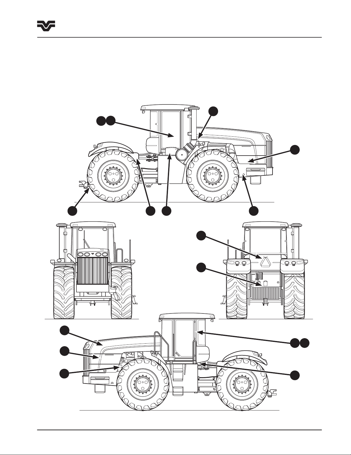
Safety Labels
Safety Labels
The following warning signs are installed on the tractor in the areas indicated. They are intended for your safety
and for those working with you. Please become familiarized with the content and location of these warning
signs.
Make sure all warning signs are legible. Clean or replace where necessary. Replacements warning signs can be
obtained from your Buhler Versatile dealer.
6
15
4
11
10
12
7
3
9
8
3
2
5
13 14
1
435/485/535
Page 15

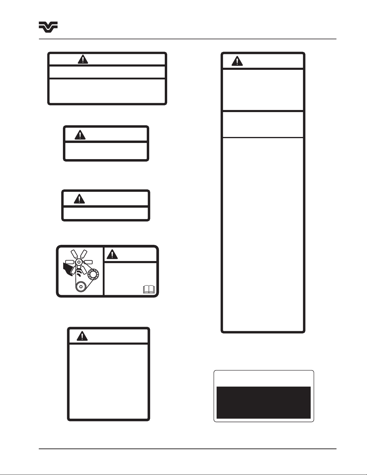
CAUTION
ATTACH IMPLEMENTS PROPERLY
Attaching clevis
type tongues
Attaching clevis
type tongues
Pull only from drawbar or three
point hitch.
Use a safety chain when towing
implement.
•
•
•
•
86000550-C
WARNING
AVOID POSSIBLE
INJURY OR DEATH
Do not start engine by shorting
across starter terminals. Engine can
start and machine can move when
starting safety switch is by-passed.
Start engine only from operator’s
seat with transmission in neutral and
the parking brake applied
86000552-C
WARNING
CONTENTS UNDER PRESSURE
Accumulator charged to 69 bar (1000 psi).
Pump service brakes at least ten times
with engine off to release pressure before
loosening any fittings connected to the
accumulator.
86034047
WARNING
ENGAGE PARK BRAKE
BEFORE EXITING
TRACTOR
86034142
CAUTION
DO NOT CONNECT JUMPER CABLE TO NEGATIVE POST OF DISCHARGE BATTERY
BATTERY BOOST INSTRUCTIONS
86000551-D
•
Apply parkbr ake, set transmis sion in neutral a nd turn all elec trical connection s off
•
Connect one end of jumper cab le to positive te rminal of boosti ng battery and ot her
end to posit ive terminal of d ischarged battery
•
Connect one end of negative c able to negative post of battery and other end to
tractor fram e at least 300 mm (12") from dis charged battery
•
DO NOT LEAN OVER BATTERIES WHILE MAKING CONNECTIONS
•
DO ENSURE POSITIVE AND NEGATIVE CLAMOS ARE NOT IN CONTACT
•
DO ENSURE VEHICLES ARE NOT IN CONTACT
•
86001239
ROLL OVER PROTECTIVE STRUCTURE
FOR TRACTORS: 435/485/535
MEETS OSHA REGULATION
PROTECTIVE STRUCTURE
PART NO: 86031286
CERTIFIED TO CSA STANDARD
86033283
F1-3A
1-14
Section 1 - Safety
Safety Labels
1. ROPS Certificate - Located left underside of cab.
2. Slow-Moving Vehicle - Located on rear of cab.
5. Implement Attaching - Located above the drawbar
at the rear of the tractor.
6. Accumulator Pressure - Located on the fender
support above the multifunction valve.
3. Tie down brackets
- Located on frames.
4. Park Brake - Located
inside cab on right hand window
8. Battery Boosting - Located on the underside of
the battery cover.
435/485/535
7. Jump starting - Located on the left
side frame next to the starter.
Page 16
CAUTION
PRESSURIZED SYSTEM
Remove cap slowly
86000548-C
CAUTION
HOT EXHAUST SYSTEM COMPONENTS
86000549-C
WARNING
ARTICULATING JOINT
STAY CLEAR OF THIS AREA WHEN ENGINE IS RUNNING
TO PREVENT PERSONAL INJURY
Engage articulation lock before lifting tractor, transporting tractor on another vehicle,
performing maintenance in articulation area or operating stationary PTO equipment.
86000554-C
Shut off engine before servicing articulation area.
Disengage lock before driving the tractor,
•
•
•
CAUTION
This roll over protective structure meets
OSHA and other safety standards when
installed in accordance with approved
factory mounting instructions
The protection afforded may be impaired if it
has been subjected to alteration, structural
damage, or involved in an overturn accident.
In these cases the entire structure must be
replaced.
BE SURE OPERATION AND SAFETY
INSTRUCTIONS ARE GIVEN TO
ANYONE USING THIS TRACTOR AT
THE TIME OF INITIAL ASSIGNMENT
AND ANNUALLY THEREAFTER.
BEFORE STARTING:
WHEN OPERATING:
BEFORE DISMOUNTING, SERVICING,
CLEANING OR ADJUSTING TRACTOR
OR IMPLEMENT:
FAILURE TO FOLLOW ALL OF THE
ABOVE INSTRUCTIONS COULD LEAD
TO SERIOUS INJURY.
Read the operator’s manual provided.
Know all the operating and safety
instructions in the operator’s manual
and on the machine.
86000553-D
•
Securely fasten your seatbelt.
•
Be sure all shields are in place.
•
Hitch only to drawbar or three point
hitch lift points.
•
No riders should be permitted in the
cab or on the tractor.
•
Make sure everyone is clear of the
machinery.
•
Do not allow children to operate the
tractor.
•
Avoid operating tractor near holes,
ditches or steep slopes.
•
Bring tractor to a complete stop. Lower
implement, shift transmission to neutral,
set park brake.
•
Stop engine and wait for all moving parts
to come to a complete halt. Remove key
if leaving tractor.
•
Avoid jerky starts or stops.
•
Use flashers and extremity lights
when required.
•
Reduce speed when turning, crossing
slopes and on rough, slick, or muddy
surfaces.
•
Be sure the transmission is in neutral,
PTO is disengaged and implement
hydraulic levers are in neutral.
•
86033512
CAUTION
This instructional seat
has been provided only
for training operators
or diagnosing machine
problems.
Keep all other riders off
the tractor and equipment.
Always wear your seat belt.
WARNING
Ke ep ha nds a nd
cl oth in g a wa y f ro m
ro tat in g f an an d bel ts .
Fa ilu re to c omp ly co ul d
re sul t in de ath
or se ri ous i nju ry.
86501511-E
F1-3B
IMPORTANT
CLUTCH PEDAL MUST BE
DEPRESSED & TRANSMISSION
MUST BE IN NEUTRAL TO
START TRACTOR
86034143
1-15
Section 1 - Safety
Safety Labels
9. Pivoting Frames - Located on the right and left
sides.
1
0. Radiator Cap Pressure - Located on the left side
of the hood at the access hole for the radiator cap.
11. Hot Exhaust - Located on the right side frame
under engine hood.
12. Engine Cooling Fan - Located on both sides of
radiator under the engine side shields
14. ROPS Caution - Located inside cab on left hand
door post.
13. Instructional Seat - Located inside cab on left
hand door post.
15. Clutch Pedal operation - Located inside cab on
right hand window
435/485/535
Page 17
F1-6
F1-4
F1-5
1-16
Section 1 - Safety
Additional Safety Items
Additional Safety Items
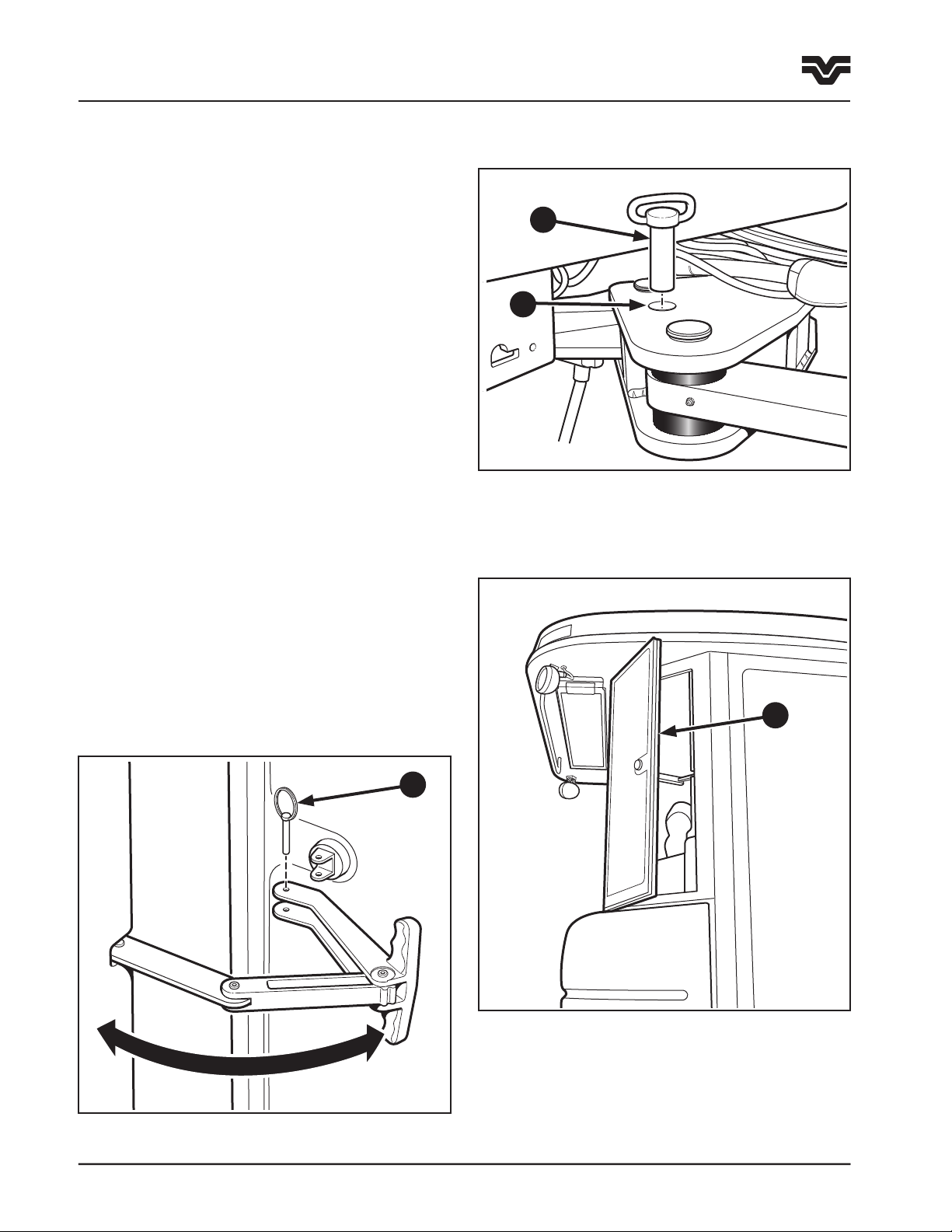
Articulation Locks
1. Use the articulation lock during stationary
applications, servicing, jacking or overhaul
operations. Do not use when the tractor is
operating.
1
2. Before engaging the lock, drive the tractor to a
level surface, put the steering straight, engage the
park brake, put the gearshift in neutral and stop
the engine.
3. Remove the pin (1) from the storage position
located on the right of the swing frame and insert
the pin through the hole on the left of swing
frame (2).
NOTE: It may be necessary to start the engine and
articulate the frame slightly to enable the
articulation pin to seat properly through the swing
frame and front frame.
Emergency Exit
1. The cab has an emergency exit located in the right
rear of the cab (3). To operate, pull out the
pin (4) attaching the lever to the glass window.
This will allow the window to open beyond
the latch. If greater access is required, the
silicone hinge/seal can be cut to remove the
window completely.
2
3
435/485/535
4
Page 18

1-17
Section 1 - Safety
Safety Cab
Safety Cab
A safety cab incorporates a Roll Over Protective
Structure (ROPS). Safety belts are standard fitted
equipment for the tractor at the time of factory
assembly. The safety belt, when used by the operator,
maximizes the protection offered by the ROPS.
WARNING: ALWAYS USE YOU SAFETY BELT WITH
THE CAB/ROPS TO PREVENT BEING THROWN
FROM THE TRACTOR IN THE EVENT OF ROLLOVER.
SAFETY BELTS SAVE LIVES WHEN THEY ARE
USED.
Information regarding the safety cab/ROPS and safety
belt are available from your authorized Buhler Versatile
dealer.
ROPS Maintenance and Inspection
After the first 50 hours of operation and every 1500 of
operation (or yearly, whichever comes first):
Damage to the Cab/ROPS
If the tractor has rolled over or the cab has been
damaged (such as striking an overhead object during
transport), it must be replaced to provide the original
protection.
IMPORTANT: Do not try to weld or straighten the
cab/ROPS.
After an accident, check for damage to the cab/ROPS,
operator’s seat, safety belt and safety belt mountings.
Replace all damaged parts before operating the
tractor.
WARNING: NEVER ATTACH, CHAINS, ROPES
OR CABLES TO THE CAB/ROPS FOR PULLING
PURPOSES. ALWAYS PULL FROM THE TRACTOR
DRAWBAR. BE CAREFUL WHEN DRIVING THROUGH
DOOR OPENINGS OR UNDER LOW OVERHEAD
OBJECTS. MAKE SURE THERE IS SUFFICIENT
OVERHEAD CLEARANCE FOR THE CAB/ROPS.
1. Check the torque of the cab/ROPS mounting bolts,
as detailed in the lubrication and maintenance
section of this manual.
2. Check the operators seat mounting bolts and safety
belt mounting bolts. Tighten the seat mounting
bolts to 40 N
damaged parts.
·m (30 ft-lbs.). Replace any worn or
WARNING: IF THE CAB/ROPS IS REMOVED OR
REPLACED, MAKE CERTAIN THAT THE PROPER
HARDWARE IS USED AND THE RECOMMENDED
TORQUE VALUES ARE APPLIED TO THE ATTACHING
BOLTS. SEE YOUR AUTHORIZED BUHLER
VERSATILE DEALER.
435/485/535
Page 19

1-18
435/485/535
Page 20

2-1
Section 2 - General Information
Contents
Section 2 Contents - General Information
Tractor Orientation . . . . . . . . . . . . . . . . . . . . . . . . . . . . . . . . . . . . . . . . . . . . . . . . . . . . . .2-2
Overall Description . . . . . . . . . . . . . . . . . . . . . . . . . . . . . . . . . . . . . . . . . . . . . . . . .2-2
Tractor Terminology. . . . . . . . . . . . . . . . . . . . . . . . . . . . . . . . . . . . . . . . . . . . . . . . .2-2
Tractor Identification Data . . . . . . . . . . . . . . . . . . . . . . . . . . . . . . . . . . . . . . . . . . . . . . . . .2-3
Vehicle Identification Plate . . . . . . . . . . . . . . . . . . . . . . . . . . . . . . . . . . . . . . . . . . .2-3
Tractor Identification . . . . . . . . . . . . . . . . . . . . . . . . . . . . . . . . . . . . . . . . . . . . . . . .2-3
Engine Identification . . . . . . . . . . . . . . . . . . . . . . . . . . . . . . . . . . . . . . . . . . . . . . .2-4
Transmission Identification . . . . . . . . . . . . . . . . . . . . . . . . . . . . . . . . . . . . . . . . . . .2-4
Front & Rear Axle Identification . . . . . . . . . . . . . . . . . . . . . . . . . . . . . . . . . . . . . . . .2-5
Protective Shielding . . . . . . . . . . . . . . . . . . . . . . . . . . . . . . . . . . . . . . . . . . . . . . . . . . . . .2-6
Engine Side Covers . . . . . . . . . . . . . . . . . . . . . . . . . . . . . . . . . . . . . . . . . . . . . . . . .2-6
Starter Solenoid Shield . . . . . . . . . . . . . . . . . . . . . . . . . . . . . . . . . . . . . . . . . . . . . .2-6
Battery Cover . . . . . . . . . . . . . . . . . . . . . . . . . . . . . . . . . . . . . . . . . . . . . . . . . . . . .2-6
Break-In period . . . . . . . . . . . . . . . . . . . . . . . . . . . . . . . . . . . . . . . . . . . . . . . . . . . . . . . .2-7
Towing the Tractor . . . . . . . . . . . . . . . . . . . . . . . . . . . . . . . . . . . . . . . . . . . . . . . . . . . . . .2-8
Transporting the Tractor . . . . . . . . . . . . . . . . . . . . . . . . . . . . . . . . . . . . . . . . . . . . . . . . . .2-9
435/485/535
Page 21

2-2
F2-3
F2-2
F2-4
F2-1
Section 2 - General Information
Tractor Orientation
Tractor Orientation
Overall Description
The Models 435, 485 and 535 tractors are
classified as 4–wheel drive articulating vehicles.
The tractors consist of front and rear frame assemblies
which steer by pivoting at the center articulation
joint.
The front frame, (1) incorporates the engine, fuel
tanks, transmission, front drive axle, and cab. The rear
frame, (2) incorporates the rear drive axle and supports
any implements that are operated by the tractor. This
type of design allows for greater flexibility of weight
distribution, depending upon operating conditions and
type of implement. The operator can ballast the tractor
to best suit the needs of the particular operation.
The construction of the tractor is a modular-type
construction. This means that the major components
are individual units which are supported within
the front and rear frames. This makes for easier
serviceability and longer life due to reduced structural
stress on components.
Tractor Terminology
This manual uses the following terms to describe
tractor function and directional relationships:
Front (1) - The engine end of the tractor. This direction
will also be referred to as the “Forward Direction
of Travel”.
Right (2) - The console side of the cab.
Rear (3) - The drawbar end of the tractor, which is
used for pulling implements.
Left (4) - The doorway side of the cab.
1
2
1
2 3
4
Articulation - The ability to steer by pivoting
between front and rear frame sections.
435/485/535
Oscillation - The ability of a vehicle to twist,
allowing travel over uneven terrain.
Page 22

F2-7
F2-6
Tractor Identification Data
MODEL
TRANSMISSION
HYDRAULIC PUMP
FWD-FACTOR
BUHLER VERSATILE INC.
TRACTOR NUMBER
ENGINE
FRONT AXLE
UNIT
REAR AXLE
HYDRAULIC LIFT
SPECIAL ORDER
F2-5
The tractor and its major components are identified
using serial numbers and/or manufacturing codes.
These codes are recorded on the Vehicle Identification
Plate, (ID plate).
NOTE: Tractor identification data must be supplied
to the dealer when requesting parts or service.
Identification data is needed to aid in identifying the
tractor if it is ever stolen.
Please record the following identification data in the
sample ID plate, right.
The following information provides the locations of the
identification data.
2-3
Section 2 - General Information
Tractor Identification Data
Vehicle Identification Plate
The Vehicle Identification Plate (1) is located on the
left rear underside corner of the cab.
The ROPS identification plate (2) is located adjacent
to it.
Tractor Identification
The tractor serial number (3) is stamped on the front
frame.
This serial number stamp is used in the event that the
Tractor Identification Plate is removed or mutilated.
1
2
3
435/485/535
Page 23

2-4
F2-9S
F2-8
F2-9P
Section 2 - General Information
Tractor Identification Data
Engine Identification
The Cummins engine used in your Buhler Versatile
4WD tractor is serviced solely by the Cummins
Engine Company through its authorized dealers and
distributors. Many Buhler Versatile dealers are
authorized Cummins dealers. If your dealer is
not, he will arrange for the engine service on
your tractor to be carried out by an authorized
Cummins engine dealer or distributor.
For service, warranty, and parts information, contact
your Buhler Versatile dealer.
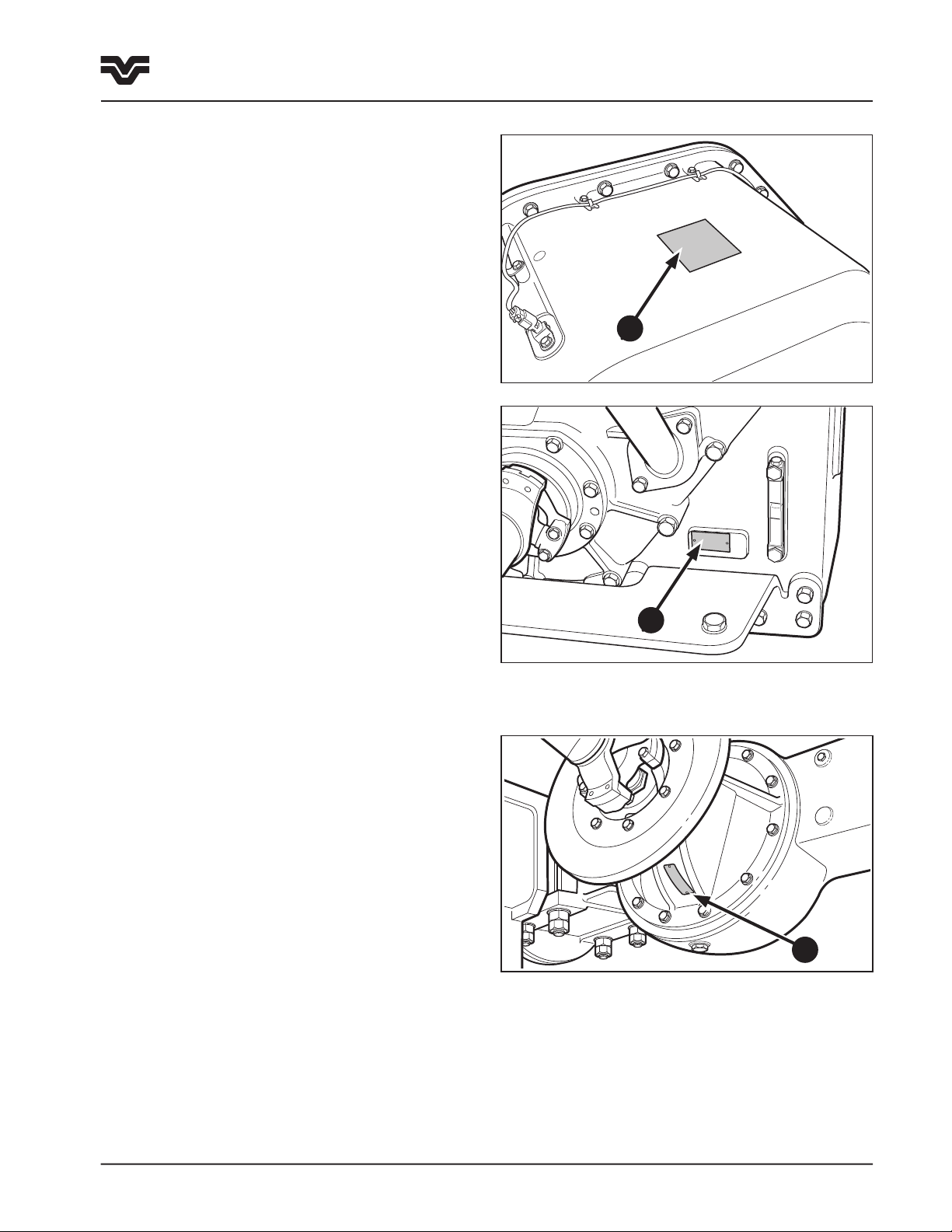
For the 435, 485 and 535 tractor (Cummins QSX15
engine), the Engine Identification Plate (1) is located
on the front left side of the engine block below the
valve cover.
Transmission Identification
Synchromesh Transmission (12 x 4 Synchronized)
The serial number plate is on the right rear of
the transmission case (2). This is a 6-digit alpha
numeric number.
1
1407 Twindisc Powershift Transmission
The serial number plate is located on the left rear of
the transmission case (3).
435/485/535
2
3
Page 24
F2-10
CAT TA22 Powershift Transmission
F2-9C2
F2-9C1
There are two serial number plates, located on the top
of the transmission case (1) and on the bottom rear
right below the transmission oil level sight glass (2).
2-5
Section 2 - General Information
Tractor Identification Data
1
Front & Rear Axle Identification
On the underside (or topside) of the input shaft is
the Differential Identification Plate (3) containing
differential model information.
NOTE: Make a copy of the information recorded in the
preceding paragraphs and keep in a safe location in
the event your operator’s manual is lost or destroyed.
2
3
435/485/535
Page 25
2-6
F2-13
F2-12
F2-11
Section 2 - General Information
Protective Shielding
Protective Shielding
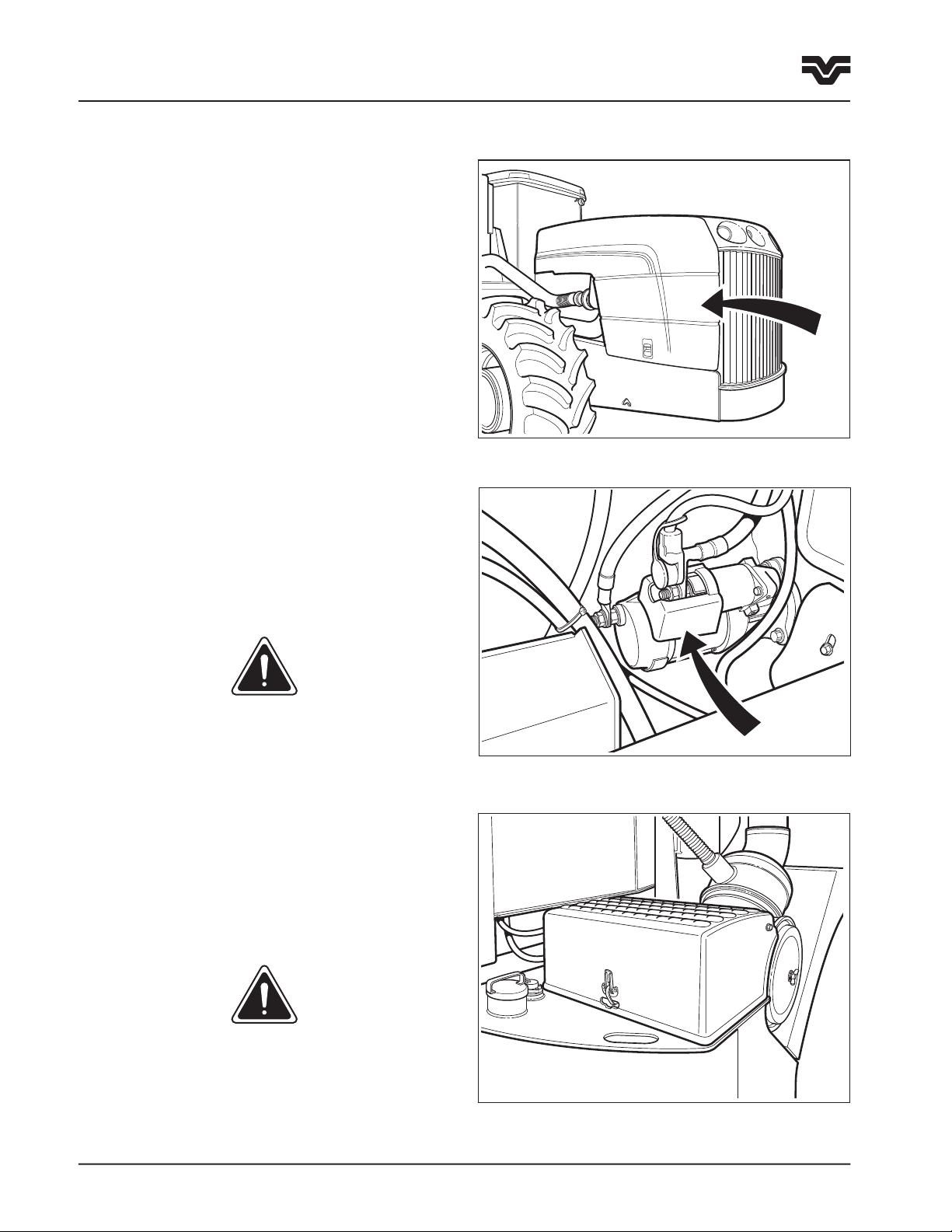
Engine Side Covers
The side covers protect the operator from hot and/or
moving parts. Do not operate the tractor unless the
engine side covers are in place and latched.
Starter Solenoid Shield
The shield covers the starter solenoid electrical
connections to prevent accidental contact. The
shield must be installed whenever the batteries are
connected to the electrical system. Always disconnect
battery before removing the shield.
DANGER: NEVER ATTEMPT TO START THE TRACTOR
BY BYPASSING THE WIRES TO THE STARTER
MOTOR.
Battery Cover
The battery cover protects the batteries from damage
and the electrical connections from accidental contact.
The battery cover must always be in place and latched
during operation.
WARNING: INSTALL ALL PROTECTIVE SHIELDS
BEFORE STARTING OR OPERATING THE TRACTOR.
435/485/535
Page 26

Break-in Periods
2-7
Section 2 - General Information
Break-In Period
The first 50 hours of operation are the most critical for
insuring long and dependable tractor life. Please carry
out the following procedures:
1. Review the tractor Pre-delivery Checklist contained
in the assembly manual with your dealer. Be sure
all applicable items on the sheet have been
checked.
2. Check all fluid levels and be sure all systems are
filled with the correct fluids for your operating
conditions.
3. Check the engine, transmission, and hydraulic oil
levels hourly during the first 10 hours of
operation.
4. Inspect the tractor for leaks hourly during the first
10 hours of operation.
5. Torque the wheel bolts to 715 N
after the first hour of operation and after every three
hour of operation for the first day. Re-tighten to the
specified torque daily until wheel hardware
maintains the specified torque.
6. Operate the engine at 3/4 load as much as possible
during the first 50 hours (3/4 load is approximately
one gear lower than would be normally used to pull
a matched load).
·m (525 ft-lbs)
Engine Break-in
The Cummins engine used in Buhler Versatile 4WD
tractors has been run on a dynamometer before
installation but not enough to be considered broken
in.
1. Do not operate the engine at more than 3/4 load
for the first 24 hours of operation. Full load should
only be held for short intervals during the next 24
hours of operation.
2. Check the oil level every 8 to 10 hours for the first
100 hours of operation.
3. Follow the recommendations outlined in the
Cummins manual supplied with your tractor.
7. Do not operate the engine at idle speed or maximum
horsepower for more than 5 minutes at a time for
the first 50 hours.
8. Check the frame pivot pin, drag link and steering
cylinder cap screw torques after the first 10 hours
of operation. Torque the frame pivot pin to 1365
N
·m (1000 ft-lbs) and the remaining pins to 175
N
·m (130 ft-lbs).
9. Have your dealer complete the “First 50-Hour
Service” checklist at the end of this manual.
435/485/535
Page 27

2-8
Section 2 - General Information
Towing the Tractor
Towing The Tractor
IMPORTANT: The tractor should only be towed a short
distance such as out of a building. Do not tow down
roadways or as a method of transport. Haul the tractor
on a trailer.
If towing the tractor is necessary, use a strong chain
or cable of sufficient strength to tow the vehicle.
Consult your Buhler Versatile Dealer. Tow the tractor
BACKWARD from the drawbar or FORWARD from both
of the front tie-down slots. Use the tie-down slots in
the front and rear frames to attach the chains to the
tractor.
WARNING: WHEN THE TRACTOR IS TOWED AND
THE ENGINE IS NOT RUNNING THERE WILL BE NO
BRAKES AVAILABLE ON THE TRACTOR RESULTING
IN A POSSIBLE COLLISION. ALWAYS USE A SOLID
TOWING BAR BETWEEN THE TRACTOR AND THE
TOWING VEHICLE. THE TOWING VEHICLE MUST
BE OF ADEQUATE SIZE TO STOP THE TOWED
TRACTOR.
IMPORTANT: Do not tow the tractor by hooking to the
engine cross brace.
1. Engage the parking brake, then shift transmission
in neutral. Attach the chain to the tractor.
2. If possible start the engine and let the engine run
so that full use can be made of the power steering
and brakes. If the engine cannot be run engage
the articulation lock. (see page 1-12)
IMPORTANT: If the engine is not operational, and
the transmission internal components are rotated by
the axle drive shafts for a long period of time,
possible transmission damage due to lack of
lubrication may result.
IMPORTANT: When the engine is running, the
clutch, transmission input shaft, and transmission
output shafts will also be driven. Be sure that
these components are functional prior to starting
the engine.
3. Release the parking brake and tow the tractor.
CAUTION: DO NOT TOW THE TRACTOR FASTER
THAN 8 KPH (5 MPH). ENGAGE THE ARTICULATION
LOCK WHEN IT IS NOT POSSIBLE TO STEER THE
TRACTOR (WITH THE ENGINE RUNNING).
WARNING: ONLY USE CABLES OF SUFFICIENT
STRENGTH TO TOW THE TRACTOR. IF A CABLE
BREAKS OR SLIPS, IT MAY WHIP WITH SUFFICIENT
FORCE TO CAUSE SERIOUS INJURY. WHEN USING
A CHAIN, ATTACH WITH THE HOOK OPEN SIDE
FACING UP; IF IT SLIPS, IT WILL DROP DOWN
INSTEAD OF FLYING UPWARD CAUSING SERIOUS
INJURY.
435/485/535
Page 28
F2-14
F1-6
Transporting the Tractor
2-9
Section 2 - General Information
Transporting
1. Haul the tractor with all four wheels on to a flatbed
trailer.
2. Remove the outer duals or triples during
transporting unless special permits allow for over width hauling. Consult local authorities for
information on over-width hauling.
3. Make an accurate measurement of the highest point
on the tractor when it is loaded on the transporter.
Consult local authorities regarding over-height
hauling based on the measurements taken.
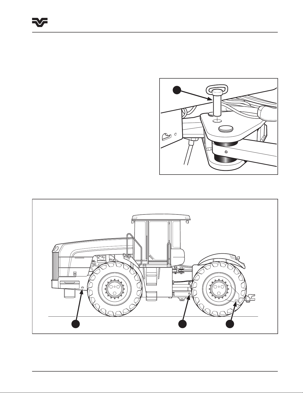
4. Tie-down brackets are located in the following
positions.
Cutout slots (1) are located on either side of the front
frame to allow a chain hook to be used to hold down
the front end of the tractor.
Tie-down brackets are located on either side of the rear
frame, in the articulation area (2) and on the drawbar
cage (3). Use a chain of adequate size, routed through
the brackets to hold down the tractor.
6. Always fully engage the park brake and install
the articulation lock pin (4) when transporting the
vehicle.
4
1
2 3
435/485/535
Page 29

2-10
435/485/535
Page 30

Section 3 Contents - Operation
3-1
Section 3 - Operation
Contents
Introduction . . . . . . . . . . . . . . . . . . . . . . . . . 3-2
Pre-operation Checks . . . . . . . . . . . . . . . . . . 3-2
Precautionary Statements . . . . . . . . . . . . . . . 3-2
Welding & Battery Charging . . . . . . . . . . . . . . 3-3
The Cab . . . . . . . . . . . . . . . . . . . . . . . . . . . . 3-4
Entering the Cab . . . . . . . . . . . . . . . . . .
Cab Features . . . . . . . . . . . . . . . . . . . . .
Emergency Exit / Rear Window . . . . . . . .
Operator’s Seat . . . . . . . . . . . . . . . . . . . . . . . 3-6
Seat Belt . . . . . . . . . . . . . . . . . . . . . . . .
Standard Seat . . . . . . . . . . . . . . . . . . . .
Deluxe Seat . . . . . . . . . . . . . . . . . . . . . .
Instructional Seat . . . . . . . . . . . . . . . . 3-11
Controls & Instruments Overview . . . . . . . . . 3-12
Forward Operator Controls . . . . . . . . . . 3-12
Overhead Controls . . . . . . . . . . . . . . . . 3-13
Right Side Console Controls . . . . . . . . . 3-14
Steering Wheel and Column Adjustments . . . 3-16
Park Brake . . . . . . . . . . . . . . . . . . . . . . . . . 3-16
Foot Brake & Decelerator Pedal . . . . . . . . . . 3-17
Forward Operator Control Console . . . . . . . . 3-18
Overhead Control Details . . . . . . . . . . . . . . . 3-20
Climate Control & Air Conditioning . . . . . . . . 3-21
Electronic Instrument Cluster . . . . . . . . . . . 3-25
Indicator, Warning Lamps & Alarm . . . .
EIC Tractor Performance Monitor . . . . . .
Fault Codes . . . . . . . . . . . . . . . . . . . . .
EIC Calibration . . . . . . . . . . . . . . . . . . 3-41
Right Side Console Controls . . . . . . . . . . . . 3-46
Synchromesh Transmission . . . . . . . . . .
Powershift Transmission . . . . . . . . . . . .
Hand Throttle . . . . . . . . . . . . . . . . . . .
Cruise Control . . . . . . . . . . . . . . . . . . .
Autoshift (CAT TA22 Transmission) . . . .
Differential Lock . . . . . . . . . . . . . . . . .
Remote Hydraulic Controls - Manual . . . . . . 3-47
Remote Hydraulic Controls -
Electro-Hydraulic . . . . . . . . . . . . . . . . . . . . 3-49
Tractor Start-up and Engine Operation . . . . . 3-50
Cold Weather Starting. . . . . . . . . . . . . . 3-51
Tractor Boosting . . . . . . . . . . . . . . . . . .
3-4
3-4
3-5
3-6
3-7
3-9
3-27
3-36
3-40
3-46
3-46
3-46
3-47
3-47
3-47
3-53
Tractor Operation . . . . . . . . . . . . . . . . . . . . 3-54
Hand Throttle Operation . . . . . . . . . . . .
Decelerator Pedal . . . . . . . . . . . . . . . . .
Cruise Control Operation . . . . . . . . . . . .
Stopping the Tractor . . . . . . . . . . . . . . .
Transmission Operation . . . . . . . . . . . . . . . . 3-57
Synchromesh Transmission Operation . .
1407 Powershift Transmission Operation
CAT TA22 Powershift Transmission Operation
Drawbar Operation . . . . . . . . . . . . . . . . . . . 3-67
External Lighting . . . . . . . . . . . . . . . . . . . . 3-70
Hydraulic System Overview . . . . . . . . . . . . . 3-72
Hydraulic Schematic Diagram . . . . . . . .
Remote Control Valve Operation - Manual . . . 3-74
Lockout Levers . . . . . . . . . . . . . . . . . .
Hydraulic Flow Controls . . . . . . . . . . . .
Hydraulic Quick Couplers . . . . . . . . . . .
Operating Continuous Flow Hydraulic
Equipment . . . . . . . . . . . . . . . . . . . . . 3-80
Hydraulic Motor Applications . . . . . . . . 3-81
Remote Control Valve Operation -
Electro-Hydraulic . . . . . . . . . . . . . . . . . . . 3-82
Electro-Hydraulic Control Pods . . . . . . .
Engagement Switch . . . . . . . . . . . . . . .
Manual Operation . . . . . . . . . . . . . . . .
Programmable Operation . . . . . . . . . . .
Flow Control Adjustment . . . . . . . . . . .
Hydraulic Quick Couplers . . . . . . . . . . .
Connecting Single-Acting Cylinders . . . .
Connecting Double-Acting Cylinders . . .
Operating Continuous Flow Hydraulic
Equipment . . . . . . . . . . . . . . . . . . . . . 3-89
Hydraulic Motor Application . . . . . . . . .
Bleeding Remote Cylinders . . . . . . . . . .
Wheels, Tires & Articulation Blocks . . . . . . . 3-91
Wheel Installation-Single . . . . . . . . . . . 3-91
Wheel Installation-Dual . . . . . . . . . . . .
Wheel Installation-Triple . . . . . . . . . . . .
Tire Selection . . . . . . . . . . . . . . . . . . .
Articulation Blocks . . . . . . . . . . . . . . . .
Ballasting . . . . . . . . . . . . . . . . . . . . . . . . . 3-98
Ballasting Weights . . . . . . . . . . . . . . . . . . 3-102
3-54
3-54
3-54
3-56
3-57
3-59
3-61
3-73
3-75
3-77
3-78
3-83
3-84
3-85
3-85
3-87
3-88
3-89
3-89
3-90
3-90
3-92
3-93
3-95
3-96
435/485/535
Page 31

3-2
Section 3 - Operation
Introduction
Introduction
Read this section thoroughly. It details the location
and operation of the various instruments, switches
and controls on this tractor.
Do not start the engine or attempt to drive or operate
the tractor until you are fully accustomed to all the
controls. If in doubt about any aspect of operation of
the tractor, consult your authorized dealer.
Pay particular attention to the break–in
recommendations in section 2 to ensure that your
tractor will give the long and dependable service for
which it was designed.
Perform lubrication and maintenance schedules as
detailed in Section 4.
Pre–operation Checks
After completing the daily lubrication and maintenance
operations, perform a walk around visual inspection of
the tractor. Pay particular attention to the following
items:
• Fan belt for cracks
• Engine area for accumulation of debris
• Hoses, lines, and fittings for leaks or damage.
• Tires for damage
• Hardware for looseness
• Driveline and hydraulic pump areas for leaks or
debris accumulation
• Make sure the tractor is ballasted properly for the
work to be performed (see “Ballasting” in this
Section)
• Check dual or triple wheel mounting bolt torque
Make any necessary repairs before using the tractor.
Precautionary Statements
• DO NOT OPERATE THE TRACTOR IN A CLOSED
BUILDING.
• BEFORE STARTING THE ENGINE, BE SURE ALL
OPERATING CONTROLS ARE IN NEUTRAL OR
OFF AND THE PARK BRAKE IS ENGAGED.
• OPERATE ALL CONTROLS ONLY FROM THE
OPERATOR’S SEAT.
• STOP THE ENGINE BEFORE SERVICING THE
TRACTOR.
• KEEP ALL SHIELDS IN PLACE.
• STOP THE ENGINE BEFORE RAISING THE
ENGINE SIDE SHIELDS.
• USE HAND HOLDS AND STEPS WHEN MOUNTING
AND DISMOUNTING THE TRACTOR.
• USE THE ARTICULATION LOCK IN STATIONARY
APPLICATIONS AND SERVICING. DO NOT USE
WHEN THE TRACTOR IS MOVING.
• ON HIGHWAYS, SIGNAL BEFORE STOPPING,
TURNING, OR SLOWING THE TRACTOR.
• USE PROPER SAFETY DEVICES TO WARN OF
SLOW–MOVING VEHICLE WHEN DRIVING ON
PUBLIC ROADS. CHECK WITH LOCAL
AUTHORITIES CONCERNING HIGHWAY TRAVEL.
• WIDE TRANSPORT MARKER LIGHTS ARE
SUPPLIED WITH ALL TIRE OPTIONS. USE
THEM.
435/485/535
Page 32

Welding & Battery Charging
3-3
Section 3 - Operation
Welding & Battery Charging
Precautions: Welding
To avoid damage to the electronic/electrical systems,
always observe the following:
1. Always disconnect
before carrying out any welding on the tractor or on
any implement attached to the tractor.
2. Position the welder ground cable clamp as close to
the welding area as possible. Never weld on one
frame member (i.e., front or rear frame) and have
the ground strap of the welder on the other frame.
Doing this can cause damage to the hoses,
articulation bearings, and wire harnesses in the
articulation joint area.
3. Never allow welding cables to lay on, near or across
any electrical wiring or electronic component while
welding is in progress.
4. On Powershift transmission equipped units, remove
the electrical connectors attached to the
transmission electronic controller, even when
the negative cable of the battery is disconnected,
to provide additional protection to the transmission
controller.
5. Always have an assistant standing by with a fire
extinguisher to put out any fires that may start due
to welding procedures.
6. Always completely clean the area to be welded so
that it is free of any grease, fuel or oil before
welding.
BOTH cables from the batteries
Precautions: Battery Charging
1. Never make or break any of the charging circuit
connections, including the connection at the
batteries, when the engine is running.
2. Never short any of the charging components to
ground.
3. Do not use a booster battery of higher than 12 volts
nominal voltage.
4. Always observe correct polarity when installing the
batteries or using a booster battery to jump start
the engine. Follow the instructions in this manual
when jump starting the tractor. Connect positive to
positive and negative to negative.
5. Always disconnect the negative cable from the
batteries when charging the batteries in the tractor
with a battery charger.
WARNING: BATTERIES CONTAIN SULPHURIC ACID.
IN CASE OF CONTACT WITH SKIN, FLUSH THE
AFFECTED AREA WITH WATER FOR FIVE MINUTES.
SEEK MEDICAL ATTENTION IMMEDIATELY.
AVOID CONTACT WITH THE SKIN, EYES OR
CLOTHING. WEAR EYE PROTECTION AND
PROTECTIVE CLOTHING WHEN WORKING NEAR
BATTERIES.
435/485/535
Page 33

3-4
F3-3
UNLOCK
Position 1
LOCK
Position 2
F3-2
F3-1
Section 3 - Operation
Cab Features
The Cab
Entering the Cab
The cab has been designed for operator comfort and
convenience. The roof and floor are insulated to reduce
noise.
3
1
CAUTION: THE CAB IS NOT DESIGNED TO PROVIDE
A ”SPRAYER SAFE” ENVIRONMENT FOR THE
OPERATOR. WHEN APPLYING CHEMICALS FROM A
SPRAY UNIT, DO NOT RELY ON THE CAB FILTER
ELEMENTS TO PROVIDE PROTECTION TO THE
OPERATOR FROM AIRBORNE CHEMICALS.
Cab features include:
• Air suspension operators seat
(Optional semi active seat)
• Tinted glass
• Opening rear window
• Fresh air heater/defroster
• Air-conditioning
• Interior lighting
• Instructional seat (optional)
• Storage tray
• Trouble light (optional)
• Cigarette lighter and ashtray
• Radio/CD (optional)
• Accessory power sockets
3
2
4
The cab is entered through the single door (1) using
the entry ladder (2) and grab handles (3) located on
the left side of the tractor. The door is hinged at the
rear and is held in the fully open position by a gas
spring.
The push-button door latch is located on the outside
bottom corner of the door (4).
The door latch can be locked with the ignition key.
The latch is unlocked in position 1 and locked in
position 2.
To open the door from inside squeeze the door latch
(5) while pushing door open.
The inside latch will open the door even if the door is
locked from the outside.
435/485/535
5
Page 34

F1-4
Rear Window / Emergency Exit
F1-5
The right rear window, (1), can be opened to provide
ventilation. The window can be locked open, closed,
or positioned partially open.
To lock the window, pull the handle in and forward in
an arc. The handle will fold, go over center and lock.
3-5
Section 3 - Operation
Cab Features
To open the window, pull the handle back and push
out. The handle will unfold. There are four detents in
the handle, which will hold the window in a partially
open position. To lock in the full open position,
continue rotating the handle outward until the handle
stops. This is also an over center position, which will
prevent the window from closing unless the latch is
pulled.
The rear window also serves as an emergency exit in
the event that the cab door cannot be opened. To
operate, pull out the pin (2) attaching the handle to
the glass window.
This will allow the window to open wide enough for
exit. If greater access is required, the silicone hinge/
seal can be sliced through with a knife to remove the
window completely.
1
2
435/485/535
Page 35

3-6
F3-4
Section 3 - Operation
Cab Features - Seating
Operator’s seat
The tractor is equipped with a choice of operator’s
seat.
The Standard Seat
The Deluxe Seat
(Equipped with: adjustable headrest, heated seat
cushion, semi-active air suspension system.)
NOTE: Before operating the tractor, it is important to
adjust the seat, steering wheel, and controls to the
most comfortable position.
Seat Belt
1
WARNING: THIS TRACTOR IS EQUIPPED WITH A
RETRACTABLE SEAT BELT. ALWAYS USE THE SEAT
BELT.
The seat belt automatically adjusts for the size of the
individual in the seat.
To fasten the belt, pull the belt from the reel and push
the tongue end (1) into the buckle end (2) until a click
indicates it is properly engaged.
To release the belt, push the red release button (3) on
the buckle and remove the tongue from the buckle.
To clean the belt, sponge with clean, soapy water. Do
not use solvents, bleach or dye on the belt as these
chemicals will weaken the webbing.
Replace the belt when it shows signs of fraying,
damage or general wear.
2
3
435/485/535
Page 36

F3-5
Standard Seat
The seat is equipped with controls to permit the
following adjustments for personal comfort.
NOTE: All adjustments should be made in the following
order while sitting in the seat.
Adjust the seat using the following procedures:
NOTE: With the engine off, adjust the seat by
turning the ignition switch to the “ACC” position.
DO NOT START THE ENGINE.
1. Height/Weight Adjustment
Raise - Depress the top of the switch. Release when
the desired height is obtained.
Lower - Depress the bottom of the switch. Release
when the desired height is achieved.
3-7
Section 3 - Operation
Cab Features - Seating
1
2
2. Backrest Angle Adjustment
Lift the lever and tilt the backrest to the desired
position. Release the lever to lock the backrest in
position.
NOTE: The backrest will tilt backward far enough to
contact the rear window.
3. Fore/Aft Position Adjustment
Pull up on the lever and move the seat fore/aft
through the 178 mm (7”) adjustment range to the
desired position. Release the lever to lock the seat
into position.
4. Fore/Aft Float
Pull up on the lever to allow the seat to float fore and
aft 51 mm (2”).
seat into position.
Push down on the lever to lock the
3
6. Storage tray
Pull out for access.
5
4
6
5. Lateral Float
Pull up on the lever to allow the seat to float laterally
51 mm (2”). Push down on the lever to lock the seat
into position.
435/485/535
Page 37

3-8
F3-6
Section 3 - Operation
Section 3 - Operation
Cab Features
Cab Features - Seating
6. Dampener Adjustment
The firmness of the ride can be adjusted as follows:
Soft - Rotate the control knob clockwise to decrease
the firmness of the seat bounce.
Firm - Rotate the control knob counterclockwise to
increase the firmness of the seat bounce.
7. Swivel Adjustment
The seat can be adjusted to:
• Lock in the forward position.
• Lock in one position to the left of center.
• Lock in one of four positions to the right of center
(increments of 7° for a total of 28° rotation)
• Provide a free swing position without locking in any
position.
To adjust the seat swivel:
1. Move the swivel control lever partially to the
rear.
9
7
6
2. Swing the seat to the desired position.
3. Release the lever to lock the seat into position.
NOTE: Moving the control lever fully rearward will
provide the free swing position.
8. Lumbar Adjustment
Adjust as follows:
Increase support - Rotate the wheel down.
Decrease support - Rotate the wheel upwards.
9. Armrest Angle Adjustment
Rotate the roller on each armrest to adjust to the
desired angle.
Both armrests can also be raised up to the full vertical
position for easy access.
8
435/485/535
Page 38

F3-7
Deluxe Seat
The seat is equipped with controls to permit the
following adjustments for personal comfort.
NOTE: All adjustments should be made in the following
order while sitting in the seat.
Adjust the seat using the following procedures:
NOTE: With the engine off, adjust the seat by
turning the ignition switch the “ACC” position.
DO NOT START THE ENGINE.
1. Height/Weight Adjustment
Depress the top of the switch to raise the seat. Release
when the desired height is obtained.
Depress the bottom of the switch to lower the seat.
Release when the desired height is achieved.
3-9
Section 3 - Operation
Cab Features - Seating
1
6
5
2
2. Backrest Angle Adjustment
Lift the lever and tilt the backrest to the desired
position. Release the lever to lock the backrest in
position.
NOTE: The backrest will tilt backward far enough to
contact the rear window.
3. Fore/Aft Float
Pull up on the lever to allow the seat to float fore and
aft 51 mm (2”). Push down on the lever to lock the
seat into position.
4. Lateral Float
Pull up on the lever to allow the seat to float laterally
51 mm (2”). Push down on the lever to lock the seat
into position.
5. Swivel Adjustment
4
3
7. Storage tray
Pull out for access.
7
Pull up on the lever to swivel the seat. Push down on
the lever to lock the seat into position.
6. Fore/Aft Position Adjustment
Pull up on the lever to move the seat forward
or backward to the desired position. Push down
on the lever to lock the seat into position.
435/485/535
Page 39

3-10
F3-8
Section 3 - Operation
Cab Features - Seating
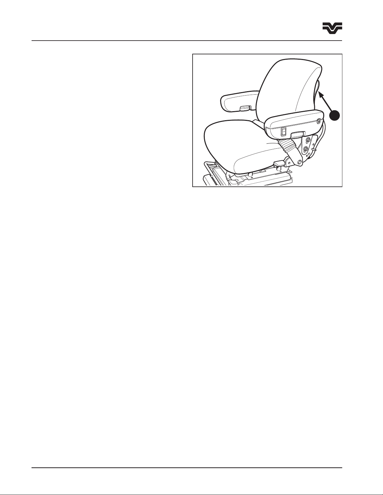
7. Heated seat cushion
The seat incorporates a thermostatically controlled
heating element within the seat cushion which
maintains a comfortable working temperature in cold
conditions. Depress the top of the switch to activate.
The indicator switch lamp will illuminate. To switch
off, depress the bottom of the switch.
8. Dampener Adjustment
The seat incorporates a semi-active suspension system
that greatly reduces vibration to the operator.
NOTE: The suspension system is factory calibrated
and should only be serviced by an authorized Buhler
Versatile dealer.
Depress the top of the switch to increase the increase
the firmness of the ride.
Depress the bottom of the switch to soften the ride.
9. Lumbar Adjustment
10
11
7
8
Adjust as follows:
Increase support - Rotate the wheel down.
Decrease support - Rotate the wheel upwards.
10. Armrest Angle Adjustment
Rotate the roller on each armrest to adjust to the
desired angle.
Both armrests can also be raised up to the full vertical
position for easy access.
11. Headrest Adjustment
The headrest can by raised to the desired position by
pulling upward, using the handle incorporated in the
back of the headrest.
9
435/485/535
Page 40

F3-9
Instructional Seat (Optional)
3-11
Section 3 - Operation
Cab Features - Seating
An instructional seat (1) with seat belt is available for
the purpose of providing seating for training a new
operator on the operation of the tractor.
WARNING: INSTRUCTIONAL SEAT IS USED ONLY
FOR INSTRUCTING OR SERVICE DIAGNOSING ONLY.
DO NOT PERMIT OTHERS TO RIDE, ESPECIALLY
CHILDREN. SEAT BELT MUST BE WORN AT ALL
TIMES.
A strap is provided to secure the seat cushion in a
raised position (2) when the seat is not being used for
training. This will expose the utility tray incorporating
a cup holder and storage tray.
The seat back is designed to carry a laptop computer
in the lowered position (3).
1
2
3
435/485/535
Page 41

3-12
OFF
HEAD
LOWER
F2
SYSTEM STATUS
SPEED
PTO RPM
AREA
ENG
HRS
START
STOP
PTO ON
HYD FILTER
TRANS PRESS
INTERCOOLER
ALTERNATOR
COOL LEVEL
COLD START
AIR FILTER
TRAILER BRAKE
TRAILER 1
DIFF LOCK
FUEL LEVEL
ENG OIL PRESS BATTERY VOLTS
GEAR
L
H
n/min
RPM
km/h
MPH
540
PTO
1000
SERVICE
HOUR HOUR OFF
ALARM
PTO
AREAFUEL
ON
%SLIP
1000
USED GAL
IMP WIDTH
CAL
540
RESV
DISTFTMETERS
VOLTS
ENGINE
ENGINE
ENGINE
TRANS FILTER
HYD TEMP
% SLIP
DISTANCE
SELECT
CABIN
TEMP
PANEL DIM
TIMED
EXIT
F1
15
5
10
COOLANT TEMP
ETHER
UPPER
OVER
RIDE
ACC
OFF
STOP
RUN
START
F1 F2
F3-10
Section 3 - Operation
Cab Controls & Instruments
Controls and Instruments Overview
The information on the following pages identifies,
locates and describes the function of the controls and
instruments located in the cab.
WARNING: DO NOT OPERATE THE TRACTOR UNTIL
YOU ARE THOROUGHLY FAMILIAR WITH THE
LOCATION AND OPERATION OF ALL CONTROLS.
7
10
The controls have been divided into the following four
areas:
Forward Operator Controls
Overhead Controls
Right Side Console Controls
Additional Cab Controls
89
7
6
5
4
11
12
13
14
15
3
2
1
20
19
18
17
16
435/485/535
Forward Operator Controls
(steering wheel omitted for clarity)
Page 42

A
U
T
O
T
E
M
P
C
O
N
T
R
O
L
F3-11
Forward Operator Controls
3-13
Section 3 - Operation
Cab Controls & Instruments
1. Key-start/stop switch, 4 position
2. Engine shut down override switch
3. Electronic Instrument Cluster (EIC) including:
4. 11 touch sensitive switches for selecting
EIC functions and aid in calibration
5. Tractor Performance Monitor (TPM)
6. Fuel level and battery voltage bar graphs
7. 26 Indicator and warning lamps
8. Central display (LCD) indicates:
Top - transmission gear information
Middle - engine speed
Bottom - hours, ground speed, PTO speed as
selected
9. Coolant temperature and oil pressure bar graphs
10. 6 touch sensitive function switches: timed exit,
panel light, cabin temperature, engine hours
11. Multi-function switch: horn, turn signal, high/low
beam
15. Clutch control pedal
16. Brake pedal
17. Decelerator pedal
18. Ashtray
19. Steering wheel tilt control lever
20. Roof beacon (optional)
Overhead Controls
21. Dome lights
22. Front windscreen wiper/washer switch
23. Rear windscreen wiper/washer switch (optional)
24. Heater/air-conditioning vents
25. Recirculation vent
26. Air conditioner on/off switch
27. Temperature control selection switch
28. Fan switch
12. Master light switch, 4 position
13. Hazard warning switch
14. Ether (cold start) button
21 22 23 27 28 29 2124 26
29. Radio (optional)
30. Rearview mirror
31. Right hand console lamp
25
3031
Overhead Controls
435/485/535
Page 43

3-14
ON
N
N
N
N
N
N
N
N
F3-13
AUTO
F3-12
(SET)
OFF
CRUISE
N
1
3
2
4
N
L
H
M
R
N
ON
STOP
AUTO
Section 3 - Operation
Cab Controls & Instruments
54321
13
12
11
10
Right Side Console Controls - Synchromesh Transmission with Manual Hydraulics
1. Gear selector
2. Range selector
3. Hydraulic lever control 1-6
4. PTO - Power Take Off (optional)
5. Fuse & relay panel cover
6. Flow controls 1-4
7.
CAT TA22 transmission autoshift switch (optional)
8. Differential lock switch (optional)
9. Hand throttle control lever
10. Cruise control +/- increment/decrement switch
11. Cruise control on/off switch
12. Cup holder
13. Cigarette lighter
14. Electro-hydraulic control pods (optional)
15. Electro-hydraulic engagement switch
8
4
8
679
15 14
7
Synchromesh transmission with optional
Electro-hydraulics
435/485/535
Page 44

3-15
(SET)
OFF
CRUISE
N
F3-14
ON
STOP
AUTO
ON
N
N
N
N
N
N
N
N
F3-13
AUTO
Section 3 - Operation
Cab Controls & Instruments
4321
12
11
10
Right Side Console Controls - Optional 1407 Twindisc or CAT TA22 Powershift Transmission
1. Bumpshift lever
2. Hydraulic lever control 1-6
3. PTO - Power Take Off (optional)
4. Fuse & relay panel cover
5. Flow controls 1-4
6.
CAT TA22 transmission autoshift switch (optional)
6. Differential lock switch (optional)
7. Hand throttle control lever
9. Cruise control +/- increment/decrement switch
10. Cruise control on/off switch
11. Cup holder
12. Cigarette lighter
13. Electro-hydraulic control pods (optional)
14. Electro-hydraulic engagement switch
9
with Manual Hydraulics
Powershift transmission with optional
Electro-hydraulics
7
67
3
58
14 13
6
435/485/535
Page 45

3-16
F3-28
ETHER
F3-15
F3-120
GEAR
Section 3 - Operation
Cab Controls & Instruments
Steering Wheel and Column
The steering column may be adjusted for tilt and
telescope to provide a comfortable operating
position.
Steering Wheel Tilt Control
To tilt the steering wheel, pull the tilt control lever
(1) upward. Position the steering wheel at the desired
angle and lock in position by releasing the control lever.
The steering wheel can be tilted upward to the top
stop to allow easy exit from the seat.
Steering Wheel Telescopic Adjustment
To telescope the steering wheel rotate the center
locking knob (2) counterclockwise and unlock the
steering column. Slide the steering wheel up or down
to the desired position and lock the column in place
by rotating the locking knob (2) clockwise.
IMPORTANT: Your tractor is equipped with hydrostatic
power steering. Never hold the steering wheel against
either of the articulation stops for more than 10
seconds or for more than a total of 10 seconds in any
one minute. Failure to observe this precaution may
result in damage to the steering system components.
Parking Brake
The parking brake (3) is located on the floor to the
right of the operator’s seat. To engage the parking
brake, pull the lever up. To disengage, raise the lever
up slightly, then depress button (4) and push the lever
down.
2
1
CAUTION: THE PARKING BRAKE MUST BE
ENGAGED BEFORE THE OPERATOR LEAVES THE
SEAT.
NOTE: A two-minute pulsating audible alarm will
sound with a flashing parking brake lamp to remind
the operator to engage the parking brake if the tractor
engine is stopped without the parking brake applied.
The parking brake indicator lamp will illuminate when
the parking brake is applied.
IMPORTANT: To prevent the tractor from being driven
with the parking brake applied a flashing “P” will be
displayed in the transmission LCD of the EIC (5) and
the parking brake warning lamp will flash along with a
continuous audible alarm. Tractors equipped with the
CAT TA22 transmission require that the parking brake
be engaged before the engine will start.
435/485/535
3
4
5
Page 46

3-17
F3-56
Section 3 - Operation
Cab Controls & Instruments
Foot Brake
The foot brake pedal (5) is located in the lower right
corner of the operator’s console near the cab floor. The
pedal should be depressed to bring the tractor to a
stop once the clutch pedal is fully depressed.
CAUTION: KEEP THE CAB FLOOR AREA FREE FROM
DEBRIS OR OBJECTS WHICH MAY OBSTRUCT THE
OPERATION OF THE BRAKE PEDAL. KEEP THE
PEDAL CLEAN AND DRY TO PREVENT YOUR FOOT
FROM SLIPPING OFF THE PEDAL.
DANGER: NEVER LEAVE THE OPERATOR’S SEAT
WITHOUT FIRST BRINGING THE TRACTOR TO A
COMPLETE STOP USING THE FOOT BRAKE, AND
THEN ENGAGING THE PARKING BRAKE.
DANGER: NEVER OPERATE THE TRACTOR IF THE
FOOT OR PARKING BRAKE DOES NOT FUNCTION
PROPERLY.
5
6
DANGER: NEVER RELY SOLELY ON THE
TRANSMISSION TO HOLD THE TRACTOR
STATIONARY WHEN PARKED; ALWAYS ENGAGE
THE PARKING BRAKE.
Decelerator Pedal
At the lower front of the right console is the decelerator
pedal (6) which can be used to reduce engine speed
when turning or while shifting. Fully depressing the
decelerator pedal will reduce the engine to an idle
speed of 1400 RPM. If the pedal is not fully depressed,
engine speed will be reduced proportionally. When
the pedal is released, engine speed will return to the
previous throttle setting.
IMPORTANT: Do not release the decelerator before
completing the turn. If the transmission is in a high
gear, the tractor will accelerate quickly, reducing the
time to correct tractor direction.
435/485/535
Page 47

3-18
F3-19
OVER
RIDE
ACC
OFF
STOP
RUN
START
F3-16
OVER
RIDE
ACC
OFF
STOP
RUN
START
Section 3 - Operation
Cab Controls & Instruments
Forward Operator Control Console
The following description details the controls located
in the forward operator’s console.
A
B
C
Ignition Switch
The ignition switch (1) has four key positions.
Position A - Accessories “ON,” Engine “OFF”
Position B - Engine and electrical equipment “OFF”
Position C - Warning lights and instruments “ON.”
Engine RUN position.
Position D - Starter motor operates
Engine Shut Down Override Switch
The rocker switch (2) allows the operator to override
the automatic shut down. See “Operating the Engine”
for details on the automatic shut down feature. The
switch should only be used to move the tractor to a
safe area for investigation and repair. Push the top of
the switch to override the shut down system. Push the
bottom of the switch to return to normal (automatic
shut down) operation.
D
1
Rotary Beacon Switch (optional)
The rocker switch (3) controls the operation of the
beacon. Push the top of the switch to operate the
beacon. Push the bottom of the switch to turn the
beacon off. Tractors without rotary beacons have a
blanking plate in place of the switch.
Ashtray and Cigarette Lighter
The ashtray (4) can be tilted out for convenient use.
To clean the ashtray, pull it upward and out from the
dash and empty.
The cigarette lighter (page 3-14) is located on the
left of the right hand console. Push the lighter in to
activate. It will automatically pop out when heated.
Return lighter to it’s socket after use.
3
2
4
435/485/535
Page 48

F3-17
OFF
HEAD
LOWER
ETHER
UPPER
Master Light Switch
F3-18
OFF
HEAD
LOWER
UPPER
The master light switch (1) has 4 positions.
Position A - Full counterclockwise is off.
Position B - Headlights and parking lights
C
3-19
Section 3 - Operation
Cab Controls & Instruments
D
Position C - Headlights and parking lights and lower
work lights
Position D - All work lights, headlights and parking
lights.
Hazard Warning Light Switch
Push the top of the rocker switch (2) to activate the
hazard lights. Push the bottom of the switch to turn
the hazard lights off.
Multi Function Switch
The lever type multifunction switch (3) operates the
horn, turn signals, headlight flash and is used to select
high or low beam.
Turn Signals - Move the lever upward to indicate a
right turn, or downward to indicate a left turn. The turn
signal warning light on the warning light bar will flash
when the signals are operated. The opposite warning
light on the warning light bar will also light, but will
remain steady. The turn signal must be manually
returned to neutral after the turn is completed.
An audible warning will sound if the turn signals are
left on for more than two minutes
Headlights (High/Low Beams) - With the master light
switch in positions B, C or D, the multifunction switch
lever can be pulled toward the steering column to
change the headlights between high and low beam.
B
A
2
1
3
C
D
B
A
4
Headlight Flash - With the master light switch in
position A (Off), the multifunction switch lever can be
pulled toward the steering column to flash the high or
low beams of the headlights.
Horn - Press the button on the end of the multifunction
switch lever to activate the horn.
Ether Cold Start Button
The ether cold start button (4) is used to inject ether,
a highly combustible substance, into the engine
intake manifold. Ether will ignite in the engine at
temperatures far below those needed to ignite diesel
fuel.
Use the ether to assist the engine starting in
temperatures at or below 0° C (32° F).
Note: See cold-weather starting on page 3-51 for
detailed operation.
435/485/535
Page 49

3-20
F3-20
F3-142
MIRROR
L
R
Section 3 - Operation
Cab Controls & Instruments
Overhead Controls
The following description details the overhead controls
located in the cab roof.
Front Windshield Wiper/Washer Switch
The front windshield wiper switch (1) is a three
position switch.
Position A - Off
Position B - Slow
Position C - Fast
Press the switch to operate the screen washer.
When the front windshield wiper switch is turned off,
the wiper arm will always park on the right side of the
windshield.
Rear Window Wiper/Washer Switch (optional)
The rear window wiper switch (2) is also a three
position switch and operates as the front windshield
switch.
B
C
A
1 2
C
B
A
Position A - Off
Position B - Slow
Position C - Fast
Press the switch to operate the screen washer.
When the rear window wiper switch is turned off,
the wiper arm will always park on the left side of the
window.
Power Heated Mirrors (optional)
The power heated mirrors controls are located on the
right side in the cab roof.
The mirror controls consist of a momentary rocker
switch (3) which activates the mirrors heating elements
for nine minutes before automatically switching off.
The mirrors are adjusted with the joystick (4). Turning
the joystick left or right to select the required mirror,
moving the joystick up and down or left and right to
obtain the desired position.
3 4
435/485/535
Page 50

Climate Controls
F3-22
AUTO TEMP CONTROL
F3-21
Heater
Before activating the heater, open the heater valve on
the rear/right side of the engine block (1). Under most
cold-weather conditions it is not necessary to have the
valve completely open.
During hot weather, shut the heater valve off. This will
ensure that no engine coolant will flow into the heater
core.
Make sure the air conditioner is deactivated except
during defrosting. To increase the cab interior
temperature for cold weather operation, start the engine
and make sure the coolant temperature bar graph
indicates two or more bars. Rotate the temperature
control switch (3) to increase the temperature. Adjust
the fan speed switch (4) to increase or decrease air
flow.
3-21
Section 3 - Operation
Cab Controls & Instruments
1
Air Conditioning Operation
CAUTION: THE AIR CONDITIONING SYSTEM USES
R134A REFRIGERANT. DO NOT MIX WITH OTHER
REFRIGERANTS. DO NOT ATTEMPT TO TOP OFF
THE SYSTEM WITH ANY OTHER REFRIGERANTS.
CONSULT A QUALIFIED TECHNICIAN FOR ALL AIR
CONDITIONING REPAIRS.
The climate controls consist of a rocker switch (2)
which activates the air conditioning, and two rotary
switches, controlling the temperature (3) and the
pressurizer fan (4).
Depress the top of the air conditioning rocker switch
(2) to activate the air conditioner. Depress the bottom
of the switch to deactivate the air conditioner.
The temperature control switch (3) is used to maintain
a constant temperature. Rotate the temperature
control switch counterclockwise to increase cooling.
Adjust the fan speed switch (4) to increase or decrease
air flow.
2 3 4
To aid in defrosting the windshield and side windows
the air conditioner and heater may be operated at the
same time. The air conditioner will remove moisture
from the air while the heater warms the air in the
cab. When the windows are clear, deactivate the air
conditioner.
435/485/535
Page 51

3-22
F3-114
F3-57
A
U
T
O
T
E
M
P
C
O
N
T
R
O
L
F3-23
F3-24
Section 3 - Operation
Cab Controls & Instruments
IMPORTANT: Always turn the air conditioner off when
cooled or dehumidified air is not required. This is
especially important during cold weather as damage to
the compressor could result. For proper air conditioner
operation, the cab air filter must be serviced regularly.
(See Lubrication & Maintenance section).
Pressurizer Vents
The pressurizer has adjustable and fixed vents to
direct air flow as required.
Fixed vents (not shown) direct air to the windshield to
aid defrosting and defogging.
Two adjustable vents (1) can be directed onto the
front side windows and door to aid defrosting and
defogging.
Four adjustable vents (2) face the operator.
Vent (3) is for air re-circulation.
321
4
Rotate the vents inside their housings to direct air as
required. The slide lever inside the vent can be moved
side to side to direct air flow to the left or right.
For additional comfort, a floor vent (4) is
provided at the bottom of the right hand console.
Sun Blind
A sun blind is provided front and rear. Pull down
on the bottom frame (5) and extend to the desired
position. Push up to retract.
Mirror
An interior rear view mirror (6) is provided for your
convenience. It is located on the right post and is
adjustable.
5
NOTE: To provide a wider view, the mirror has a
convex lens. This causes objects to appear farther
away than they are.
Console Light
A console light (7) is provided to illuminate the right
console. The light comes on when the master light
switch is set to positions B, C or D. (see page 3-19).
435/485/535
7
6
Page 52

F3-26
F3-27
F3-25
Trouble Light (Optional)
A trouble light is located in the left, rear corner
of the cab, under the rear deck. The light has a
5.5 M (18
(1) move the locking lever (2) to the left and carefully
pull the light downward while unwinding the cable
from the holder. The light base is magnetic which
enables attachment to the tractor for convenience
while working.
The light switch (3) is a two-position switch. With the
switch lever in the off position (vertical), the light is off.
With the switch lever in the on position (horizontal),
the light will come on when the cab door is open.
') power cord attached. To remove the light
3-23
Section 3 - Operation
Cab Controls & Instruments
4
3
2
The trouble light, when it is stowed in it’s cradle, is used
in conjunction with the cab dome lights to illuminate
the cab interior when the cab door is open.
NOTE: The trouble light has been designed to turn off
when the door is closed.
To stow the trouble light, reel in the cable with the
crank handle (4) inserting the pin (5) into its socket,
and lock in position with the lever (2).
Power Outlets
Three power outlets are located in the rear deck
behind the operator’s seat.
Outlet (6), 12 volt, 1-pin accessory connector.
Outlet (7), 12 volt, 3-pin accessory connection.
Outlet (8), 16-pin diagnostic connector.
Outlet (9), Cummins diagnostic connector.
Outlet (10), CAT TA22 transmission diagnostic
connector (Optional CAT TA22 Installation only)
NOTE: On earlier models a Cummins engine diagnostic
cable, BVI p/n: 86033779 is supplied with the tractor
and is located in the storage tray under the seat. This
cable connects to the 16 pin connector (8) and the
Cummins insite tool harness.
1
10
9
8
7
5
6
The 3-pin accessory plug (7) has 3 terminals.
Pin 1 - Key switched 12 volt power source protected
by a 20-amp fuse.
Pin 2 - Live 12 volt power source
protected by a 20-amp fuse.
Pin 3 - Ground.
1
2
3
435/485/535
Page 53

3-24
F3-118
F3-110
A
B
C
F3-26
Section 3 - Operation
Cab Controls & Instruments
Dome Lights
Two dome lights (1) are provided in the cab roof to
illuminate the interior. Each light can be set to one of
three positions.
Position A - On when the door is open
Position B - Off
Position C - On
Cab-Mounted Accessory Bracket (Optional)
The cab has an optional bracket for mounting cab
accessories, ie: Implement Monitor Boxes, Gauges, CB
Radio, and Cellular Phone. The bracket is equipped
with three power outlets:
Socket (4) is a 12 volt, 1-pin accessory connector.
Plugs (5&6) are 12 volt, 3-pin accessory connections.
These plugs have 3 terminals:
Pin 1 - Key switched 12 volt power source protected
by a 20-amp fuse.
Pin 2 - Live 12 volt power source
protected by a 20-amp fuse.
1
4
5
6
Pin 3 - Ground.
Radio (Optional)
A radio/cassette or radio/CD player can be installed in
the cab of your tractor.
P/N: 86032815 - radio/cassette
P/N: 86032814 - radio/CD player
If you require installation of either of these units,
please contact your Buhler Versatile dealer.
A separate instruction manual is supplied with
each radio and should be followed for proper radio
operation.
Rotary Beacon (Optional)
A rotary beacon with a magnetic base can be mounted
in one of three locations on the roof cap.
The power cable is connected to the socket (7) located
to the left of the door underneath the roof cap.
The beacon is operated by the switch on the right
hand side of the forward control console.
1
2
3
7
The rotary beacon kit is available from you a Buhler
Versatile dealer, P/N: 86031163
435/485/535
Page 54

F3-29
Electronic Instrument Cluster
3-25
Section 3 - Operation
Electronic Instrument Cluster - EIC
7
2
1
2 3
4
526
Introduction
The following information details the operation and
programming of the Electronic Instrument Cluster
(EIC).
example of a normal operating display.
When the key-start switch is turned on, a self-test of
all the Liquid Crystal Display (LCD) segments and
warning lamps is activated, the audible alarm will
sound for approximately one second and all lamps
will be illuminated briefly to confirm that the bulbs
are functioning. The LCD background areas are
illuminated when the tractor key switch is turned on.
They also have dimmer controlled back lighting.
The EIC is divided into the following areas:
1. The central LCD displays transmission gear
information at the top. Engine speed in the middle
and operating hours/ground speed and PTO speed
at the bottom.
2. There are 26 colored indicator or warning lamps,
which provide operating information or give warning
of system malfunctions.
The above illustration of the EIC shows an
3. Fuel level and battery volts are displayed
in the right bar graphs.
4. The Tractor Performance Monitor (TPM) is
displayed on the right side of the cluster. The
TPM provides information on 3-point hitch
and other selected system information. Fault code
information is also displayed.
5. Eleven touch-sensitive switches select EIC
functions for display within the TPM. The switches
are also used for calibration purposes.
6. Four touch-sensitive switches are used to control
timed exit, cabin temperature (optional), engine
hours and instrument lighting.
7. Coolant level and engine oil pressure are displayed
in the left bar graphs.
435/485/535
Page 55

3-26
F3-31
F3-30
n/min
RPM
Section 3 - Operation
Electronic Instrument Cluster - EIC
Audible Alarm
An audible alarm will sound under the following
conditions:
• when the ignition is first switched on.
• when a warning light illuminates or a bar graph
indicates a malfunction.
The alarm will alert the operator that a malfunction
has occurred.
Depending on the severity of the malfunction, the
alarm will sound as follows:
Non-Critical Alarm - An audible alarm sounds for one
second only. The tractor will continue to operate, but
the cause of the alarm should be investigated and
corrected.
Critical Alarm - A continuous pulsating tone will
sound until the malfunction is corrected or the engine
is switched off. The engine “STOP” message will flash
in the center display for 30 seconds before automatic
engine shut down occurs. The cause of the malfunction
should be located and corrected immediately to
prevent damage to the tractor.
The audible alarm has a rotary volume control (1)
located on the left side of the steering column below
the front controls. Rotate the alarm cover to adjust
the volume.
1
Automatic Engine Shut Down
An automatic engine shut down feature is standard
equipment. This feature will automatically shut down
the engine within 30 seconds under the following
conditions:
• Transmission oil pressure low
• Engine oil pressure low
• Intake manifold temperature high-critical
• Engine coolant temperature high-critical
• Engine coolant level low
• Electrical charging system voltage low
• Engine oil temperature high-critical
WARNING: THE ENGINE SHUT DOWN FEATURE
IS FULLY AUTOMATIC. IT CAN BE OVERRIDDEN
BY THE OPERATOR TO DRIVE THE TRACTOR TO A
SAFE LOCATION. THE OVERRIDE SWITCH IS TO THE
RIGHT OF THE STEERING COLUMN AND SHOULD
ONLY BE USED TO MOVE THE TRACTOR FAR
ENOUGH TO AVOID A DANGEROUS SITUATION.
(See “Engine Shut down Override Switch Operation”
page 3-18).
435/485/535
Page 56

Electronic Instrument Cluster - EIC
F3-29
F3-32
TRAILER BRAKE
TRAILER 1
5 6 7 8 9 10 11 12 13 14
4
3-27
Section 3 - Operation
15
3
2
1
22
23
Indicator, Warning Lamps and Audible Alarm
The twenty-six colored status lamps, shown above,
provide operating information or give warning of
system malfunction. The malfunction warning lamps
are accompanied by an audible alarm.
16
17
18
192021242526
The status lamps/audible alarm function as follows:
1. Left Turn Signal
The Turn Signal lamp (1) will flash in unison with
tractor left-hand turn signal. An audible alarm will
sound if the turn signals are left on for more than two
minutes.
2. Trailer 1 Turn Signal
Not used.
3. Trailer Brake
Not used.
3
2
1
435/485/535
Page 57

3-28
F3-34
F3-33
Section 3 - Operation
Electronic Instrument Cluster - EIC
In the event of an engine fault occurring, 1 of 3
warning lamps will flash depending on the level of the
fault.
4. Engine Maintenance - Attention (white lamp)
Illuminates when engine maintenance is required.
A fault code is also displayed.
5. Engine Maintenance - Warning (yellow lamp)
Illuminates when a non-critical fault occurs in the
electronic engine control system. As soon as possible,
contact your Buhler Versatile dealer.
6. Engine Maintenance - Critical (red lamp)
Illuminates when a critical fault occurs in the electronic
engine control system.
the engine “STOP” message will flash in the center
display for 30 seconds before automatic engine shut
down occurs. The cause of the malfunction should be
located and corrected immediately to prevent damage
to the tractor.
7. Air Filter Restriction
The Air Filter lamp will illuminate accompanied by
the non-critical alarm if the fault has existed for 10
seconds. Stop the tractor and service the air filter to
prevent engine damage.
The alarm will sound and
4 5 6 7
8. Cold Start
The Cold Start lamp will illuminate when outside
temperature is at or below 0° C (32° F).
Use the ether cold start to assist engine starting in
cold weather, (see page 3-51).
9. Coolant Level Low
The Coolant Level lamp will illuminate when coolant
drops below the sender level. A critical alarm will
sound. Check for leaks and refill cooling system.
10. Alternator Charge Indicator
The Alternator lamp will illuminate steady if the
alternator is not charging the battery. The lamp will
flash and the non-critical alarm will sound if an
overcharge condition occurs.
11. Intercooler Overheated
The Intercooler lamp will illuminate and the noncritical alarm will sound when an overheat condition
occurs. The cause of the alarm should be determined
and corrected before further operation or engine
damage may occur.
8 9
10
11
435/485/535
Page 58

F3-35
12. Transmission Oil Pressure
The Transmission Oil Pressure lamp will illuminate
accompanied by the critical alarm, indicating that the
transmission lubrication circuit oil pressure is low.
The engine “STOP” message will flash for 30 seconds
before automatic shut down occurs.
Stop the engine and investigate the cause.
13. Transmission Filter
The Transmission Filter lamp will illuminate indicating
a restricted or blocked filter. The filter is now in a bypass
condition and is no longer filtering the oil returning to
the transmission. The filter should be serviced within
1 hour of operation.
14. Hydraulic Oil Temperature
The Hydraulic Oil Temperature lamp will illuminate
indicating that the hydraulic oil temperature is too
high. Stop the engine and investigate the cause.
Section 3 - Operation
Electronic Instrument Cluster - EIC
12 13
14
15
17
18
3-29
16
15. Hydraulic Filter
The Hydraulic Filter lamp will illuminate indicating
a restriction or blockage in one of the two filters. The
filter is now in a bypass condition and is no longer
filtering the oil returning to the reservoir. The filter
should be serviced within 1 hour of operation.
16. PTO On (Optional)
The PTO lamp will illuminate when the PTO switch is
engaged.
17. Diff Lock (Optional)
The Diff Lock lamp will illuminate when the differential
lock switch is engaged.
18. Right Turn Signal
The Turn Signal lamp will flash in unison with tractor
right-hand turn signal. An audible alarm will sound
if the turn signals are left on for more than two
minutes.
435/485/535
Page 59

3-30
F3-36
Section 3 - Operation
Electronic Instrument Cluster - EIC
19. Parking Brake
The Parking Brake lamp will illuminate when the park
brake is applied (raised).
WARNING: TO AVOID PERSONAL INJURY, ALWAYS
APPLY THE PARKING BRAKE BEFORE LEAVING
THE TRACTOR SEAT.
20. System Status
The System Status lamp is illuminated when all
systems are normal. It flashes when a malfunction is
detected in a system monitored by the warning lamps
or bar graphs.
21. Headlight High Beam
20 1921
The High Beam lamp will illuminate when the tractor
lights are switched to high beam.
22. F1
For future expansion/accessories
23. F2
For future expansion/accessories
24. Safety Belt
The Safety Belt lamp illuminates when the ignition
switch is turned to the “RUN” position and stays
illuminated for five seconds to remind the operator to
fasten the safety belt.
25. Auto Diff Lock
The Auto Diff Lock lamp illuminates when Auto
differential lock is engaged.
26. Timed Exit
Press to toggle between delayed lighting settings.
Lamp illuminates when timer is set.
27. Panel Dim
2322
25 2426
27 28 29
Press to toggle between illumination settings. (see
page 3-35 for details).
28. Cabin Temperature (optional)
Press to indicate cabin temperature in TPM display.
29. Engine Hours
Press to display engine hours.
435/485/535
Page 60

F3-38
Bar Graph Displays (LCD)
The four bar graphs each consist of twenty LCD
segments.
All bar graph sensors are continuously tested for faults.
If a fault occurs, the bar graph will flash and a fault
code will be stored.
Engine Coolant Temperature
The outside left bar graph (1) registers coolant
temperature. One segment of the bar graph will
be displayed if the engine is cold. The number of
segments displayed will increase as the engine warms
up. With the engine at normal operating temperature,
up to fifteen segments will be displayed. The normal
working range is indicated by the green area of the
adjacent range display.
Should the coolant temperature exceed a
predetermined level, the coolant temperature bar
graph will flash. The critical alarm will sound and the
legend “STOP” will flash in the central display for 30
seconds before automatic engine shut down occurs.
3-31
Section 3 - Operation
Electronic Instrument Cluster - EIC
1 2
Stop the engine immediately and investigate the
cause.
NOTE: The bar graph indicates engine coolant
temperature only. It is not an indication of coolant
level. The engine coolant must be checked daily.
Engine Oil Pressure
The inside left bar graph (2) indicates engine oil
pressure. With normal engine oil pressure, up to
sixteen segments of the bar graph will be displayed.
This is represented by the green area of the adjacent
range display.
Should engine oil pressure fall below a designated
level, the bar graph will flash. The critical alarm will
sound, the word “STOP” will flash in the central
display for 30 seconds before automatic engine shut
down occurs.
Stop the engine immediately and investigate the
cause.
NOTE: The bar graph indicates engine oil pressure only.
It is not an indication of oil level. The engine oil level
must be checked daily by means of the dipstick.
435/485/535
Page 61

3-32
F3-40
F3-39
Section 3 - Operation
Electronic Instrument Cluster - EIC
Fuel Level
The inside right bar graph (3) indicates fuel level.
Each segment of the bar graph display represents
one-twentieth (approximately 5 percent) of the total
fuel content of the tank.
When the fuel level falls so that only two segments of
the bar graph are displayed, the bar graph will flash
continually and the non-critical alarm will sound for
one second.
The system also has a feature to assist the operator
during refueling procedures. An audible indicator
alerts the operator when the tanks are filled to 3/4
capacity (15 bars) and 19/20 or 95% (19 bars).
NOTE: This feature only operates when the ignition
switch is set to the “RUN” position.
3 4
CAUTION: ALWAYS SHUT THE ENGINE OFF DURING
REFUELING PROCEDURES
Battery Volts
The outside right bar graph (4) indicates battery
voltage.
Central Display
Three liquid crystal displays (LCD) are located in the
center of the instrument cluster.
5. The top LCD is the digital transmission gear shift
position display.
6. The center LCD is the digital engine speed
display.
7. The lower LCD will display selected information as
follows:
• Tractor ground speed (MPH or km/h)
• PTO speed (rev/min)
5
6
7
• Engine hours accumulated (actual time)
• Service alert - as required
• Timed exit - as required
435/485/535
Page 62

F3-42
F3-41
Transmission Gear Shift Position Display
The top LCD provides a display of the gear selected.
The left figure (1) displays a letter as follows:
F - Forward gear selected*
N - Neutral selected
R - Reverse gear selected*
A - Automatic shift selected (Powershift option only)
P - Parking brake applied*
CL - Clutch depressed* (Synchromesh only)
The right figure (2) displays gear 1-12 or 1-16
depending on the transmission options.
*If the letter “P” is flashing, the display is indicating
an “Operator Prompt” where the parking brake is
inappropriately on or off or out of sequence with
the transmission control lever. To return to normal
operation, release or apply the parking brake as
appropriate. Return the transmission control lever to
neutral, release the parking brake, then shift to either
forward or reverse as desired.
3-33
Section 3 - Operation
Electronic Instrument Cluster - EIC
1 2
NOTE: A tractor equipped with synchromesh
transmission will only display gear shift position when
moving.
Engine Speed Display
With the engine running, the digital value (3) of the
engine RPM will be displayed, together with the RPM
legend (4) in the center LCD.
The engine LCD registers in increments of 10 RPM.
If a critical engine or driveline fault should occur,
the word “STOP” will flash for 30 seconds before
automatic engine shut down occurs.
3
4
435/485/535
Page 63

3-34
F3-46
F3-43
Section 3 - Operation
Electronic Instrument Cluster - EIC
Selectable Display
Using the key pad, the lower display will allow the
operator to select one of following displays:
Ground Speed Display (Speedometer)
The Ground speed (5) and the MPH or km/h legend
(6) will be displayed when the tractor is moving.
Switching between MPH or km/h is covered within
EIC programming in this section. When the display
is set to another mode the ground speed may be
recalled at any time by touching the GROUND SPEED
button (7).
NOTE: The speedometer senses rotation of the rear
axle and may be subject to errors caused by the effects
of wheel slip, tire pressures/condition, etc. If the
optional radar sensor is installed, the tractor senses
true ground speed for greater measurement accuracy.
5 6
NOTE: The lower central display will automatically
show ground speed if the tractor is traveling at more
than 20 km/h (12.4 MPH ).
Engine Hour Meter
When the KEY-START switch is turned on, the LCD
will display the hours the engine has operated (8) and
the hour meter symbol (9).
Driving the tractor will cause the display to change
automatically to ground speed. The hour meter display
may be recalled at any time by touching ENGINE
HOUR button (10).
With the engine running, the hour meter will
accumulate hours in increments of 0.1 hours until
1999.9 hours are reached. After that time, the hour
meter will accumulate complete hours only, e.g. 2000,
2001 hours, etc.
NOTE: Accumulated hours are stored in the computer
permanent memory which is not affected by
disconnecting the tractor batteries.
The hour meter may be programmed to remind the
operator when the next scheduled service is due.
7
11
89
10
Service Alert
When a Service Alert is reached, the word “SERVICE”
(11) will flash along with the selected display. See
“Setting the service alert intervals” on page 3-41.
435/485/535
Page 64

Timed Exit
The Timed Exit feature enables the worklights and
headlights to be set to remain on for a period of time
after the tractor has been switched off.
The TIMED EXIT button (1) is used to set up the
exit timer. Pressing the switch once will temporarily
display the status of the timer in the lower section
of the central LCD panel. Pressing the TIMED EXIT
button while the status is displayed will cycle forward
through each of the possible timer settings. The timer
may be set in 10-second increments up to a maximum
of 60. When the timer is set to zero, the display will
show “OFF.”
3-35
Section 3 - Operation
Electronic Instrument Cluster - EIC
When the key switch is turned off, the worklights and
headlights will stay on for the specified number of
seconds.
A “Timed Exit” status light (2) illuminates whenever
the timer is set.
Panel Dim
The PANEL DIM button (3) controls the brightness of
the EIC backlight and the warning lights.
The EIC maintains four brightness settings:
1. Daytime Dim
2. Daytime Bright
3. Night Dim
4. Night Bright
Pressing the PANEL DIM (3) button toggles between
“Bright” and “Dim” settings. When the headlight/
worklight rotary switch is in the “OFF” position, The
“Daytime” settings are active. With the headlight/
worklight rotary switch “ON” the “Night” settings are
active.
1 23
4
The brightness of the active set-point can be set to any
level between 1 (dim) and 11 (brightest). To increase/
decrease the brightness level, hold down the PANEL
DIM switch (3) while pressing the UP arrow button
(4). To decrease the brightness level, hold down the
PANEL DIM button (3) and press the DOWN arrow
button. Each time the arrow button is pressed, the
brightness will increase or decrease by one level. All
four settings will be saved when the key is turned off.
435/485/535
Page 65

3-36
F3-53
PTO
%SLIP
DIST
AREA
DISTANCE
% SLIP
SELECT
PTO RPM
CABIN
TEMP
AREA
HOUR
FUEL
VOLTS
HOUR
AREA
AREAFUEL
F3-47
Section 3 - Operation
EIC - Tractor Performance Monitor (TPM)
EIC Tractor Performance Monitor (TPM)
Introduction
The Tractor Performance Monitor (TPM) is located in
the lower right-hand corner of the EIC display.
The monitor is controlled by eleven touch sensitive
buttons as detailed.
The following information can be accessed by toggling
the select button (1) together with the arrow buttons
(2) to obtain the required display. Shortcut display
button (3), where available, can also be used.
Diagram (F3-53) shows an overview of the display
navigation.
123
Selectable Display Information
• Distance measurement in feet or meters
• Area per hour forecaster (acres or hectares)
• Area accumulated (acres or hectares)
• Wheel slip percentage with adjustable alarm
point (optional feature)
• Fuel per hour
435/485/535
• Fuel per area
• Cabin temperature
• Battery voltage
• PTO speed (optional)
Page 66

F3-48
SPEED
PTO RPM
AREA
START
STOP
HOUR
AREA
FT
% SLIP
DISTANCE
SELECT
Selectable Display Information
F3-49
SPEED
PTO RPM
AREA
START
STOP
OFF
AREA
ON
FT
% SLIP
DISTANCE
SELECT
F3-136
The following information may be selected for
display:
Area Per Hour Forecaster
(see page 3-43 for calibration)
Area Per Hour Forecast is displayed by pressing the
AREA button (1) or toggling the SELECT button. The
“AREA/HOUR” legend (2) will display, together with a
forecast of the area that will be worked in one hour (3)
if the current rate of work is continued.
This forecast is based on the last 5 seconds running
average. The forecast may be in acres (FT) (4) or
hectares (METERS).
3-37
Section 3 - Operation
EIC - Tractor Performance Monitor (TPM)
2 13
The unit of measure can be changed between FT/
METER. See “EIC programming” in this section.
NOTE: If the radar option is not installed, area per
hour calculations are based on axle speed and are
subject to inaccuracies caused by wheel slip that may
be present.
Area Accumulator (see page 3-43 for calibration)
Accumulated area (total area worked) (5) is displayed
by depressing the AREA button (1) until “AREA” and
“ON” (6) will be displayed. Area is displayed in acres
or hectares. Touch the START/STOP
button (7) and
the word “OFF” (8) will display indicating the area
counter is shut off. Toggle between Area Per Hour and
Area Accumulator by pressing AREA button (1)
NOTE: A remote implement status switch
P/N: 9702509, can also be added to the tractor, by
the use of a harness located under the rear frame next
to the trailer plug. RF049B (green wire) and RF144
(black wire) (9). If extra length is needed a harness
can be purchased from you Local Buhler Versatile
dealer: P/N 86034242. In order for the harness to
work, the wire located on the tractor trailer plug pin
4 must be disconnected and the expose wire covered
with electrical tape. The green wire RF049C must be
installed into pin 4 of the tractor trailer socket. By
adding a contact switch to a trailing implement, the
area counter can be turned on and off by lowering and
raising the implement.
English display (acres), designated by “FT” legend
(10) starts to accumulate in increments of 0.1 acres.
When 1000 acres are reached, area accumulation
continues in whole acres. When 9999 acres are
reached, the display will reset to zero.
6 5
10
9
4
8
1
7
435/485/535
Page 67

3-38
F3-51
SPEED
PTO RPM
AREA
START
STOP
VOLTS
% SLIP
DISTANCE
SELECT
F3-50
SPEED
PTO RPM
AREA
START
STOP
ALARM
%SLIP
% SLIP
DISTANCE
SELECT
Section 3 - Operation
EIC - Tractor Performance Monitor (TPM)
Metric display (hectares), designated by METERS
legend starts to accumulate in increments of .01
hectares. When 100.0 hectares are reached, area
accumulation continues in increments of 0.1
hectares until 1000 is reached. The display will then
accumulate whole hectares. When 9999 hectares are
reached, the display will reset to zero.
With AREA selected, area accumulation can be reset
to zero by holding down the START/STOP button for
three seconds until a “beep” is heard from the audible
alarm.
NOTE: If the radar option is not installed, area
calculations are based on axle speed and are subject
to inaccuracies caused by wheel slip that may be
present.
Wheel Slip (with Radar Option)
Touch the % SLIP selector button (1). The “% SLIP”
legend (2) will display together with a two-digit slip
value (3) in the main TPM display. The slip value
is detected by the comparison of theoretical ground
speed (axle rotation sensor) with true ground speed
(radar sensor).
WARNING: THE RADAR GROUND SPEED SENSOR
EMITS A LOW INTENSITY MICROWAVE SIGNAL
WHICH WILL NOT CAUSE ANY ILL EFFECTS IN
NORMAL USE. ALTHOUGH THE SIGNAL INTENSITY
IS LOW, DO NOT LOOK DIRECTLY INTO THE FACE
OF THE SENSOR WHILE IN OPERATION SO AS TO
AVOID EYE DAMAGE.
Slip Alarm (with Radar Option)
A slip alarm point may be entered - see “EIC
Programming.” When wheel slip exceeds the value
entered, the alarm will sound for one second. If wheel
slip is selected, the “% SLIP” (2) legend will be
displayed. In addition, the “ALARM” (4) legend will
flash and continue to flash until wheel slip is reduced
below the preset level.
3
1 42
Battery Voltage
Touch the SELECT button (5) until the “VOLTS”
legend (6) is displayed together with a digital display
of battery voltage (7) to the nearest tenth volt.
435/485/535
6 57
Page 68

F3-52
SPEED
PTO RPM
AREA
START
STOP
OFF
ON
DIST
FT
% SLIP
DISTANCE
SELECT
F3-55
SPEED
PTO RPM
AREA
START
STOP
HOUR
FUEL
GAL
% SLIP
DISTANCE
SELECT
AREA
F3-54
SPEED
PTO RPM
AREA
START
STOP
% SLIP
DISTANCE
SELECT
Distance Measurement
3-39
Section 3 - Operation
EIC - Tractor Performance Monitor (TPM)
Touch the SELECT button (1) again and the “DIST
FT” (2) or “DIST METERS” legend will be displayed.
The tractor will now measure distance in feet or
meters. Operate the tractor normally and press the
START/STOP button (3) at the point where distance
measuring is to begin. The “ON” legend (4) will be
displayed along with a digital display of distance
traveled (5). At the end of the distance, again press the
START/STOP button (3). A digital display of distance
traveled (5) in feet or meters will be displayed with the
“OFF” legend (6). If the START/STOP button is again
pressed, additional feet or meters will be added to
the existing measurement. Pressing the START/STOP
button (3) for more than three seconds will zero the
display.
Cabin Temperature (Optional)
In tractors fitted with the automatic temperature
control system, cabin temperature can be displayed
by depressing the CABIN TEMP button (7) or by
toggling the SELECT button (8). The “Ct” legend (9)
will display, together with temperature reading (10).
5
4
6
9
10
12 3
8
7
Fuel Per Hour
Fuel per hour is displayed by toggling the SELECT
button (11). The FUEL/HOUR legend (12) will display
together with rate of fuel consumption in liters or
gallons per hour (13). (For switching between metric
and imperial see page 3-42).
Fuel Per Area
Fuel per area is displayed by selecting fuel per hour
mode and then toggling the UP and DOWN arrow
buttons (14). The fuel per area legend (15) will display
together with the related fuel consumption in liters or
gallons per hour/area.
11131512
14
435/485/535
Page 69

3-40
F3-122
SPEED
PTO RPM
AREA
START
STOP
CAL
% SLIP
DISTANCE
SELECT
F3-61
SPEED
PTO RPM
AREA
START
STOP
% SLIP
DISTANCE
SELECT
F3-137
Section 3 - Operation
EIC - Tractor Performance Monitor (TPM)
Fault Codes
In the event that a fault occurs within the tractor
electrical circuits, a malfunction warning symbol
“READ YOUR MANUAL,” (1) will flash on and off
and the code will be stored. The tractor is factory set
to display normal TPM functions and to store fault
codes.
To view fault codes as they occur, see “Turning active
fault display on/off” on page 3-42
Fault codes (2) will be displayed as flashing threedigit number preceded by the letter “F.”
The fault code indicates the tractor circuit or sensor
in which the fault lies and the type of fault, e.g., short
circuit, open circuit, sensor failure, etc.
A complete detailed list of fault codes, their cause and
remedy may be seen in “Section 5 - Troubleshooting
Charts.
If necessary, contact your Buhler Versatile authorized
dealer and quote the fault code number.
Entering Fault Codes (Mode 2)
1. Hold the SELECT button (3) for two seconds
1
2
8
4
6
2. The TPM will display “1” (4) and “CAL (5).” Use
the UP/DOWN arrows (6) to change the display (4)
to “2”
3. Hold the SELECT
button (3) for two seconds to enter
into Mode 2 (Fault Codes)
Viewing Fault Codes
Touch the LEFT/RIGHT arrow buttons (7) to cycle
through stored fault codes. Each fault code will be
displayed along with the number of times the fault
has occurred, the engine hours of the most recent
occurrence, and the position of the fault code in the
stored list.
The illustration, F3-137 shows a typical fault code
display.
8 - Fault Code, 9 - Item number, 10 - Number
of occurrences, 11 - Engine hours of the last
occurrence.
To Exit Mode 2
Touch the START/STOP (8) button to return to the
calibration menu. Touch the START/STOP
again to return to normal operation.
button (8)
5
3
9
10
11
7
8
435/485/535
Page 70

EIC Calibration
F3-122
SPEED
PTO RPM
AREA
START
STOP
CAL
% SLIP
DISTANCE
SELECT
F3-123
SPEED
PTO RPM
AREA
START
STOP
IMP WIDTH
CAL
% SLIP
DISTANCE
SELECT
Electronic Instrument Control System (EIC) Calibration
The EIC system is factory pre-calibrated with the
required operating presets and fault codes, however, it
is necessary to verify Mode 1 calibration settings and
become familiar with the calibration procedure.
To access the Electronic Instrument Control System
for programming and calibration, follow the “Entering
Operator Calibration (Mode 1)”. All programming and
calibration is done with the key switch in the “RUN”
position and the engine off.
Entering Operator Calibration (Mode 1)
1. Hold the SELECT button (1) for two seconds
3-41
Section 3 - Operation
EIC - Calibration
2. The TPM will display “1” (2) and “CAL (3).” (If it
does not, use UP and DOWN arrow
button (4) to
change the display to “1”)
3. Hold the SELECT
button (1) for two seconds to enter
into mode 1 (Operator Calibration)
4. Touch the SELECT
button (1) to cycle through the
six Operator Calibration screens:
Calibration Screen
Without
TPM
With
TPM
Implement width 1 1
Slip percent threshold - 2
Service alert/intervals 3 3
Area preset 4 4
Fault code display on/off 5 5
English/Metric units selection 6 6
1. Setting the implement width
The implement width is used in all area calculations
performed by the TPM. It is a measure of the working
width of the implement.
1. Enter the width of the implement. The selected
(flashing) digit (5) can be changed by touching
the UP and DOWN arrow
be selected by touching the LEFT and RIGHT arrow
buttons (6).
2. Once the implement width has been entered, touch
the SELECT
button (1) to confirm the change.
buttons (4). Other digits may
4
12 3
4
5
6
1
435/485/535
Page 71

3-42
F3-125
MPH
km/h
540
PTO
1000
SERVICE
F3-140
Section 3 - Operation
EIC - Calibration
2. Slip percent threshold
On tractors equipped with an optional radar speed
sensor, the slip alarm can be used to notify the
operator whenever the wheel slip percentage is above
a certain threshold.
1. To set the slip alarm threshold, enter the desired
maximum percent slip (1). The selected (flashing)
digit can be changed by touching the UP and
DOWN arrow buttons (2). Other digits may be
selected by touching the LEFT and RIGHT arrow
buttons (3). The alarm can be disabled entirely by
setting the threshold value to zero.
2. Once the desired threshold value has been entered,
touch SELECT button (4) to confirm the change.
3. Setting the service alert intervals
The two service alert intervals can be used to remind
the operator that regular scheduled maintenance
is required. The service alerts are based on engine
hours. If, for example, a service alert is set to 50
hour intervals, it will become active at 50 hours,
100 hours, 150 hours, etc. Once a service interval
becomes active, the word “SERVICE” (5) will flash in
the lower portion of the central display until the alert
is cleared by the operator.
6
2
1
3
4
5
1. To set a service alert interval, enter the desired
number of hours. The selected (flashing) digit can
be changed by touching the UP and DOWN arrow
buttons (2). Other digits may be selected by touching
the LEFT and RIGHT arrow
2. Once the interval has been entered, touch the
SELECT
3. If a service interval is active, the service alert
display will be flashing. Hold the START/STOP
button (6) to clear the alert.
button (4) to confirm the change.
buttons (3).
435/485/535
Page 72

F3-61
SPEED
PTO RPM
AREA
START
STOP
% SLIP
DISTANCE
SELECT
F3-121
SPEED
PTO RPM
AREA
START
STOP
GAL CAL
FT
% SLIP
DISTANCE
SELECT
F3-124
SPEED
PTO RPM
AREA
START
STOP
CAL
% SLIP
DISTANCE
SELECT
AREA
4. Setting the area preset
The area accumulator calculates the total area covered
by the tractor. The accumulated area is stored in the
area preset when the tractor is switched off. When the
tractor is started again, area accumulation starts from
the stored preset.
1. To modify the area preset, enter the desired area.
The selected (flashing) digit (3) can be changed by
touching the UP and DOWN arrow
digits may be selected by touching the LEFT and
RIGHT arrow
buttons (5).
buttons (4) . Other
3-43
Section 3 - Operation
EIC - Calibration
2
4
2. The area preset may be cleared by holding the
START/STOP
button (2) for two seconds.
3. Once the desired area preset has been entered,
touch the SELECT
button (1) to confirm the change.
5. Turning active fault display on/off
Whenever a fault is detected by the electrical system,
a fault code is stored in the EIC memory, and the
flashing book icon appears in the TPM display. If
active fault display is turned on the fault code will also
be displayed as a flashing number in the TPM.
1. To toggle active fault display, touch the UP and
DOWN arrow
button (4). When active fault display
is on, the display will show “ON” (6) and fault
code. When active fault display is off, the display
will only show “OFF”.
2. Touch the SELECT
button (1) to confirm the
change.
6. Selecting between Imperial and Metric units
The EIC can display measurements in either English
(Imperial) units, or in Metric units.
3
5
1
4
6
1
2
1. To select the desired display units, touch the UP
and DOWN arrow
selected, the display will show “˚F”, “GAL”, and
“FT”. When Metric units are selected, the display
buttons (4). When English units are
will show “˚C”, “L”, and “METERS”.
2. Touch the SELECT
change.
To exit Mode 1
button (1) to confirm the
Touch the START/STOP button (2) to return to
the calibration menu. Touch the START/STOP
button (2) again to return to normal operation.
4
1
435/485/535
Page 73

3-44
AD-9
SPEED
PTO RPM
AREA
START
STOP
CAL
DIST
% SLIP
DISTANCE
SELECT
OFF
AD-10
SPEED
PTO RPM
AREA
START
STOP
CAL
DIST
% SLIP
DISTANCE
SELECT
ON
AD-8
SPEED
PTO RPM
AREA
START
STOP
% SLIP
DISTANCE
SELECT
AD-7
SPEED
PTO RPM
AREA
START
STOP
CAL
% SLIP
DISTANCE
SELECT
Section 3 - Operation
EIC - Calibration
Entering Wheel speed calibration (Mode 20)
A 100 meter (328 ft) track is required to perform
wheel speed calibration.
1. Drive tractor to the start of the designated test
area.
2. Stop the tractor 10 m before the start line.
3. Press and hold the SELECT button (1) on the Tractor
Performance Monitor (TPM) display for 2 seconds
until TPM displays “1”.
4. Touch the UP arrow button (2) until the TPM
displays “20”.
5. Press and hold the SELECT button (1) on the TPM
for 2 seconds until TPM displays “DIST CAL 0”.
1
2
6. Select a low gear and drive the tractor forward.
7. As the tractor crosses the “Start Line” touch the
SELECT button (1) once. The TPM will display
“DIST CAL 1”
8. Continue driving until the tractor reaches the
“Finish Line”.
435/485/535
1
1
Page 74

AD-12
SPEED
PTO RPM
AREA
START
STOP
CAL
DIST
% SLIP
DISTANCE
SELECT
AD-11
SPEED
PTO RPM
AREA
START
STOP
CAL
DIST
% SLIP
DISTANCE
SELECT
ON
AD-13
SPEED
PTO RPM
AREA
START
STOP
METERS
% SLIP
DISTANCE
SELECT
9. As the tractor crosses the “Finish Line” touch the
SELECT button (1) once. The TPM will display
“DIST CAL 2”.
3-45
Section 3 - Operation
EIC - Calibration
1
10. Touch select button (1) again to save the
calibration. The TPM will display “DIST CAL 3”.
11. Touch start/stop button (2) twice to exit mode 20.
12. Drive the tractor around and stop 10 m before the
finish line.
Distance check
1. Touch the distance button (3) once. If the TPM does
not display “0 meters or feet” hold the start/stop
button (2) for 2 seconds to clear the display.
2. Select a low gear and drive the tractor forward.
3. As the tractor crosses the “Finish Line” touch
the start/stop (2) button once. The TPM will begin
accumulating distance traveled
2
1
3
2
4. Continue driving until the tractor reaches the “Start
Line”.
5. As the tractor crosses the “Start Line” touch
the start/stop (2) button once. The TPM should show
approximately 100 m (+/- 5 m), (328 ft (+/- 15 ft).
If not, re-run distance check.
435/485/535
Page 75

3-46
F3-65
(SET)
OFF
CRUISE
N
F
M
R
F3-62
(SET)
OFF
CRUISE
1
3
2
4
N
L
H
M
R
N
Section 3 - Operation
Right Side Console Controls
Right Side Console Controls
Synchromesh Transmission Control Levers
The synchromesh transmission is controlled by two
control levers. Range shift lever (1) and gearshift lever
(2).
The transmission has three forward gears, low, medium,
high and reverse gear controlled by the range shift
lever (1). Within each range, including reverse, there
are four synchronized speeds, 1 to 4, controlled by
gearshift lever (2). The synchronized speeds allow for
easier shifting within each range. This combination
allows for twelve forward speeds and four reverse
speeds.
Powershift Transmission Control Lever with
Neutral Lock (1407 Twindisc and CAT TA22
Transmission)
The Powershift transmission control lever (3) is used
to select forward or reverse travel and to change
transmission speeds. Move the lever forward for forward
travel and rearward for reverse travel. A neutral-lock
switch (4) is also fitted to the lever.
12
NOTE: The control lever may only be moved to the
forward or reverse positions if the neutral lock latch
on the control lever knob is depressed. Neutral may be
selected without depressing the neutral lock latch.
The Powershift transmission control lever is also used
to make instantaneous upward or downward speed
changes. Move and then release the lever to the right
for upward changes and to the left for downward
changes. See “Transmission Operation” in this section
for details.
Hand Throttle Control Lever
The lever (5) controls engine speed. Push forward to
progressively increase engine speed. Pull rearward to
reduce engine speed.
Cigarette lighter
Push the lighter (6) in until it latches. When it pops
out, remove from its socket and return after use.
Cup holder
A cup holder (7) is provided for convenience.
4
3
976 8
5
435/485/535
Page 76

F3-69
(SET)
OFF
CRUISE
N
1
3
2
4
N
N
R
ON
STOP
F3-66
F3-63
N
R
ON
STOP
AUTO
Cruise Control Operation
Cruise control automatically keeps the engine speed
at a specified RPM. Two switches control cruise
mode operation. The “CRUISE/OFF” switch (1)
enters and exits cruise mode. The “+/- (SET)” switch
(2) adjusts the cruise setting. When cruise mode is
activated, the engine returns to the last cruise
setting, if possible, based on throttle lever position.
PTO Engagement Switch - yellow (optional)
To engage the PTO depress the button (3) in the
center of the PTO engagement switch (4) and pull the
knob upwards. To disengage the PTO, push the knob
down.
3-47
Section 3 - Operation
Right Side Console Controls
1 2
CAT TA22 Transmission Autoshift Switch
(optional)
Press and release the front/symbol of autoshift
momentary switch (5) to engage the transmission auto
shift. The letter “A” will be displayed in the powershift
display when autoshift is engaged. Press and release
the switch again to disengage the autoshift function.
See page 3-64 for details of operation.
Differential Lock Switch (optional front & rear)
Press the front/symbol of differential lock switch
(6) to engage the self-holding differential. The DIFF
LOCK warning light will illuminate on the EIC when
the differential lock is engaged. Press the rear of the
switch to disengage. See page 3-66 for details of
operation. The differential lock will disengage if the
back part of the switch is depressed, if the foot brake
is applied or when ground speeds exceed 16 KPH (10
MPH).
Remote Hydraulic Valve Controls - Manual
Note: See “Remote Control Valve Operation” on page
3-74 for details of operation before use.
7
5
4
3
6
Up to six remote hydraulic control levers (7) are
located on the right console. These are color-coded to
match the quick couplers at the rear of the tractor.
The levers have four positions: neutral, extend (or
raise), retract (or lower) and float, as indicated by the
decals. When not in use, the levers should be in the
neutral position where they can be locked to prevent
accidental actuation.
Lockout Levers - Manual
Below each control lever is a corresponding lockout
lever (8) to prevent or limit travel of the control lever.
See page 3-75 for details of operation.
8
435/485/535
Page 77

3-48
F3-64
Section 3 - Operation
Right Side Console Controls
Hydraulic Flow Controls - Manual
Hydraulic flow to the remote valves 1 to 4 is controlled
by four rotary knob style flow controls (8). Each
knob can be rotated clockwise to increase flow and
counterclockwise to decrease flow.
The knobs are color coded for identification with the
remote valve it controls.
operation.
See page 3-77 for details of
8
9
435/485/535
Page 78

F3-67
ON
N
N
N
N
N
Remote Hydraulic Valve Control -
Electro-hydraulic (Optional)
Each lever (3) activates a four position remote electrohydraulic valve. From neutral pull the lever rearward
to the stop for raise. Push forward one position at a
time for neutral, lower and float.
Each lever is color coded for identification with the
remote valve it controls.
Note: See “Remote Electro-hydraulic Control Valves”
on page 3-83 for details of operation before use.
Electro-hydraulic Engagement Switch (gray)
Depressing button (1) in the center of the engagement
switch (2) while pulling upwards on the knob will
engage the electro-hydraulic controls for the rear
remote valves.
Pushing the knob down will disengage the electrohydraulic controls and all hydraulic flow to the rear
remote valves.
3-49
Section 3 - Operation
Right Side Console Controls
1 32 4
IMPORTANT: The remote valve electro-hydraulic
engagement switch is provided as an isolator stop
switch. It can be used to immediately stop operation
of the rear remote hydraulics by quickly depressing
the knob. The stop switch only controls the remote
valves and has no effect on the three point hitch
link operation, thereby isolating operation of the rear
remote hydraulics from the three point hitch link
operation.
Remote Valve Electro-hydraulic Flow Control
Knobs
Each remote valve has a flow control knob (4) to meter
oil flow. The knob controls flow from 4 to 102 L/MIN
(1 to 27 GPM). Turn the knob so the higher vertical
decal stripe is visible to increase the rate of oil flow.
Turn the knob so the lower vertical decal stripe is
visible to decrease the rate of oil flow.
for details of operation before use.
Remote Valve Electro-hydraulic Manual/
See page 3-87
programmable Operation Switches
Each remote valve has a manual/programmable
operation switch (5). When the top of the switch is
activated the lever (3) operates in the manual mode.
When the bottom of the switch is activated the lever
(3) can be operated with a programmed release to
neutral.
use.
See page 3-85 for details of operation before
5
435/485/535
Page 79

3-50
Section 3 - Operation
Tractor Start-up and Engine Operation
Tractor Start-Up and Engine Operation
WARNING: AVOID POSSIBLE INJURY OR DEATH
FROM A MACHINE RUNAWAY. DO NOT START
THE ENGINE BY SHORTING ACROSS STARTER
TERMINALS. THE ENGINE CAN START AND THE
MACHINE CAN MOVE WHEN THE STARTING SAFETY
SWITCH IS BYPASSED.
CAUTION: PREVENT INADVERTENT TRACTOR
OR IMPLEMENT MOVEMENT. BE SURE THE
HYDRAULIC CONTROL LEVERS ARE IN NEUTRAL
AND THE 3-POINT HITCH IS SET TO THE LOWEST
POSITION PRIOR TO STARTING THE TRACTOR
WHEN ATTACHED TO AN IMPLEMENT.
THE TRACTOR CAN MOVE AS SOON AS THE
ENGINE IS STARTED BY TURNING THE STEERING
WHEEL, EVEN WITH THE PARK BRAKE ENGAGED
AND THE TRANSMISSION IN NEUTRAL. BE SURE
ALL PERSONNEL ARE CLEAR OF THE TRACTOR
BEFORE STARTING.
Engine Starting
IMPORTANT: Protect the turbocharger during startup by not opening the throttle or accelerating above
1000 RPM until the engine oil bar graph reads in the
normal range.
Avoid excessive engine speed during warm-up.
1. Fasten your seat belt.
2. Put the transmission in neutral.
3. On tractors equipped with a PTO, put the switch to
the “OFF” position. A safety switch on PTO equipped models permits engine starting only
when the PTO is off.
4. Engage the park brake.
5. Check to be sure that the remote hydraulic levers
are in the neutral position.
6. On tractors equipped with a 3-point hitch, make
sure that the hitch controls are set to the lowest
position.
7. Set the engine throttle to the lowest position.
8. Turn the ignition to “RUN” to activate the electrical
accessories. Observe the warning lamps to be sure
they are functioning.
Prestart Inspection
Do the following before starting the engine each day:
1. Check the engine oil level and adjust, if
necessary.
2. Check the coolant level and adjust, if necessary.
3. Check and clean the radiator and grill for dirt and
debris, if required.
4. Check the transmission and hydraulic oil tank
levels and adjust, if necessary.
6. Check differential oil levels.
7. Inspect the condition of all belts, lights, switches,
hoses, lines, fittings, seals, tires, nuts and bolts.
Replace or tighten, if required.
8. Check the drawbar and 3-point hitch for wear,
especially around metal-to-metal contact parts.
9. Check wheel bolt torques.
9. Engage the clutch pedal
10. Turn the ignition to the “START” position to crank
the engine, and release when the engine starts.
The switch has a starter protection feature built-in.
If the switch is rotated to the start position, and
then released to the run position, it will be
necessary to rotate the switch to the stop position in
order to make another attempt to start the tractor.
This will prevent an accidental engagement of
the engine starter motor when the engine is already
running.
IMPORTANT: To prevent starter motor damage, never
crank the engine for more than 30 seconds. If the
engine does not start within 30 seconds, wait 2
minutes to cool the starter motor before recranking.
11. Once the engine has started, allow it to idle
and warm up before adding a working load.
IMPORTANT: Pay attention to the warning light bar
and electronic monitor for any indication of a problem.
Stop the tractor immediately and investigate the
problem.
435/485/535
Page 80

F3-17
OFF
HEAD
LOWER
ETHER
UPPER
Cold-Weather Starting
The ether cold starting aid may be used to assist
the engine starting in temperatures at or below 0°C
(32°F).
CAUTION: STARTING FLUID IS HIGHLY FLAMMABLE.
DO NOT USE NEAR FIRE, SPARKS, OR FLAMES. BE
SURE ALL OPERATORS READ THE CAUTIONARY
INFORMATION ON CONTAINERS.
3-51
Section 3 - Operation
Cold Weather Starting
NOTE: The vehicles electronic control system prevents
ether from being injected into the engine if the engine
coolant temperature is above 27˚ C (80˚ F).
After following steps 1 to 10 under “Engine Starting,”
proceed as follows:
1. If the engine does not start within 15 seconds
of cranking, depress the ether aid button (1) for
two seconds while the engine is cranking to inject
starting fluid and then release. If the engine does
not start after 15 more seconds, release the
ignition switch. Allow the starter motor to cool
down for two minutes, and repeat the procedure.
NOTE: The ether injection function only operates
while the start motor is cranking the engine.
IMPORTANT: Use only one starting fluid charge per
engine crank cycle of 30 seconds. Never hold the
button longer than 5 seconds, as damage to the
electric solenoid valve may result.
2. If, after the engine starts, it runs roughly while at
low idle with an outside ambient temperature
below 0° C (32° F), it is permissible to press the
cold start button and inject an additional amount
of starting fluid into the engine to aid in engine
warm-up.
1
IMPORTANT: Pay attention to the warning light bar
and electronic monitor for any indication of a problem.
Stop the tractor immediately and investigate the
problem.
NOTE: If the engine fails to start after three attempts,
use a block heater or other means to warm the
engine.
NOTE: The cold start system injects a 4.8 cc metered
shot of starting fluid into the engine with each
depression of the switch.
ATTENTION: Use a maximum of three injections of
starting fluid into the engine for initial start-up and
engine warm-up. If the engine will not start or will not
smooth out, shut the tractor off and investigate the
cause. See “Engine Troubleshooting” in Section 4 of
this manual.
3. Once the engine has started, allow it to warm up
before putting it under load.
435/485/535
Page 81

3-52
F3-68
Section 3 - Operation
Cold Weather Starting
Engine Block Heater
Block heaters are standard equipment on Buhler
Versatile tractors. The block heater cord (1) is
located on the right side of the engine beneath the
turbocharger.
A 3-wire 15-amp extension cord is required to
connect the block heater to a grounded 115-volt
electrical outlet.
WARNING: TO AVOID SHOCKS OR OTHER INJURIES,
NEVER USE AN UNGROUNDED OR INADEQUATE
EXTENSION CORD. ALWAYS USE A GROUNDED
3-WIRE EXTENSION CORD WITH A 3-WIRE PLUG
WHICH IS RATED FOR AT LEAST A 15-AMPERE
LOAD, AND PROTECTED BY A SUITABLE FUSE OR
CIRCUIT BREAKER.
To operate the heater, plug the heater cord in for at
least four hours before attempting to start the engine.
Maximum starting ability is usually obtained after four
hours of heater operation.
Disconnect the cord when the engine has started.
Make sure that the cable is safely secured after use.
1
WARNING: ELECTRICAL SHOCK HAZARD! BE
SURE CORDS ARE PROPERLY GROUNDED. DO NOT
HANDLE IF WET. DO NOT PLUG THE HEATER IN IF
NOT IMMERSED IN COOLANT, IT MAY OVERHEAT
AND BURST CAUSING INJURY.
435/485/535
Page 82

3-53
Section 3 - Operation
Tractor Boosting Procedure
Tractor Boosting
CAUTION: WHEN SERVICING BATTERIES,
DISCONNECT THE NEGATIVE (BLACK) CABLES
BEFORE THE POSITIVE (RED) CABLES. WHEN
CONNECTING CABLES, CONNECT THE POSITIVE
(RED) CABLE FIRST, THEN THE NEGATIVE (BLACK).
THIS WILL REDUCE THE POSSIBILITY OF SPARKING
AND BATTERY EXPLOSION.
WARNING: ALL BATTERIES GENERATE
HYDROGEN GAS, WHICH IS HIGHLY FLAMMABLE.
IF IGNITED BY A SPARK OR FLAME, THE GAS MAY
EXPLODE VIOLENTLY CAUSING A SPRAY OF ACID,
FRAGMENTATION OF THE BATTERY AND POSSIBLE
SEVERE PERSONAL INJURY, PARTICULARLY TO
THE EYES.
THEREFORE, AS A SAFETY PRECAUTION:
Connection Procedure
1. Set the park brake, put the transmission in neutral,
PTO clutch control and all accessories OFF.
2. Attach one end of the booster cable (red) to the
positive terminal of the booster batteries and the
other end of the same cable (red) to the positive
terminal of the center battery on the tractor.
3. Attach one end of the negative cable (black) to the
negative terminal of the booster battery, and the
other end of the same cable (black) to a ground
on the tractor frame at least 305 mm (12
from the discharged batteries.
TO THE NEGATIVE POST OF THE DISCHARGED
BATTERIES.
4. Be sure that the clamps from one cable do not
touch the clamps of the other cable. Do not lean
over the battery when making connections.
5. Start the tractor following normal engine starting
procedures.
6. When the tractor starts, remove the booster cables.
Disconnect the negative cable (black), then the
positive cable (red).
DO NOT CONNECT
")
• WEAR PROTECTIVE CLOTHING AND GOGGLES.
• DO NOT SMOKE OR EXPOSE THE BATTERY TO
OPEN FLAME.
• DO NOT CONNECT OR DISCONNECT LIVE
CIRCUITS.
FOLLOW THE CONNECTION PROCEDURE AS
OUTLINED.
7. If the tractor fails to start, charge the batteries.
The 435, 485 and 535 tractors have three batteries
connected in parallel. Each battery having 950 CCA
(BCI Group 31).
435/485/535
Page 83

3-54
F3-69
(SET)
OFF
CRUISE
N
1
3
2
4
N
F3-56
Section 3 - Operation
Tractor Operation
Tractor Operation
Hand Throttle Control Lever
The tractor is equipped with a hand throttle, located
on the right console. Rated operating speed is 2100
RPM. Idle speed is 875 RPM. High idle no load speed
is 2225 RPM.
To increase engine speed, move the lever (1) forward
(rabbit). Pulling the lever backward will reduce engine
speed (turtle).
Fuel consumption can be reduced by operating at
lower engine speeds under light load.
Decelerator Pedal
At the lower front of the right console is the decelerator
pedal (4) which can be used to reduce engine speed
when turning or while shifting. When fully depressed,
engine speed will drop to 1400 RPM. If the pedal
is not fully depressed, engine speed will be reduced
proportionally. When the pedal is released, engine
speed will return to the previous throttle setting.
2 3 1
IMPORTANT: Do not release the decelerator before
completing the turn. If the transmission is in a high
gear, the tractor will accelerate quickly, reducing the
time to correct tractor direction.
Cruise Control Operation
Cruise control automatically keeps the engine speed
at a specified RPM. Two switches control cruise mode
operation. The “CRUISE/OFF” button (2) enters and
exits cruise mode. The “+/–(SET)” button (3) adjusts
the cruise setting.
When cruise mode is activated, the engine returns to
the last cruise setting, if possible, based on throttle
lever position.
The cruise function can be set to any engine RPM
between idle and high idle, but the operating cruise
RPM cannot exceed the RPM set by the hand throttle.
For example, if the cruise setting is 1800 RPM but
the hand throttle is at a normal 1700 RPM position,
cruise will not increase the RPM above 1700 RPM.
Operating cruise RPM always stays about 100 RPM
under the normal throttle RPM setting.
Setting - Move the throttle handle higher than the
desired cruise setting and press the “CRUISE” button
(2) to enter cruise operation.
435/485/535
4
The engine cruise will not engage unless the throttle
lever is set to a higher operating speed than the cruise
set point. The engine speed will remain at the cruise
setting RPM.
Adjust the cruise setting with the “+/–(SET)” button
(3). Set the cruise mode with the throttle lever at
Full Throttle (throttle lever fully forward) whenever
possible. Cruise function will disengage if the cruise
RPM is set to a value equal to the throttle position
RPM, moving the throttle to a higher position will
return cruise function.
The “+/–(SET)” button will change the setting 10
RPM per momentary push. When the button is held
down, the RPM will continue to move up or down.
However, the dash RPM display will not keep up with
RPM changes when the button is held down. In this
case, it is advisable to estimate the setting by ear, wait
for the dash to catch up, and fine tune the RPM using
momentary pushes.
Page 84

It is never possible to set the cruise higher than the
F3-56
F3-69
(SET)
OFF
CRUISE
N
1
3
2
4
N
current throttle lever position.
If the last cruise setting was above the throttle position,
the system will remember that cruise setting unless
the “+/–(SET)” button is pressed in cruise mode. The
cruise RPM will return to the stored cruise setting if
the throttle is moved above that RPM.
The electronic system remembers the current cruise
control setting at all times. The cruise setting remains
in memory after the cruise switch is turned off,
after the engine is shut off, or if the batteries are
disconnected.
Alternate Engine Speed Overrun
The alternative engine speed overrun feature of the
electronic engine controls provide a higher ground
speed when traveling over the road with the tractor.
3-55
Section 3 - Operation
Tractor Operation
2 3 1
All QSX 15 engines in 435, 485 and 535 tractors
have a rated engine speed of 2100 RPM. Actual high
idle engine speed, when the throttle lever is placed
in the full forward position, is 2225 +/– 50 RPM.
Overrun of the engine will occur in normal loaded
operating conditions when tractor ground speed is
below approximately 18.5 KPH (11.5 MPH).
In situations where engine load is minimal and
tractor ground speed is high, above 18.5 KPH (above
11.5 MPH), the Electronic Engine Control System
will progress to an alternate engine speed overrun
condition. The full throttle overrun will now be 2350
+/– 50 RPM). An example of this would be a tractor
traveling at 12.9 KPH (8 MPH), over the road, with
the throttle lever fully forward and the cruise switch
in the OFF position. Maximum engine RPM shown on
the EIC of the tractor will be 2225 +/– 50 RPM. If the
transmission is shifted into a higher gear and ground
speed increases above 18.5 KPH (11.5 MPH), the
engine will accelerate to a new higher speed, with the
EIC now displaying a maximum engine speed of 2350
+/– 50 RPM.
If tractor ground speed is reduced below 18.5 KPH
(11.5 MPH), the system will revert to the 6% normal
overrun mode.
IMPORTANT: Loads placed on the engine while roading
(implements, road grade) will affect tractor ground
speed and the alternate speed overrun feature.
4
Deceleration (manual or pedal) - When in cruise mode
and hand throttle (1) moves lower than the cruise
setting, the cruise RPM decreases as well and stays
100 RPM less than the normal RPM for that throttle
position. The RPM will increase back up to the cruise
setting if the throttle handle is moved forward again.
Example: With the throttle handle at Full Throttle,
the cruise is set to 1800 RPM. When the throttle
handle is moved back past the normal 1800 RPM
position, the cruise speed will drop to 1700 RPM and
continue to decrease as the throttle decreases. When
the handle moves back up to full throttle, the cruise
speed increases until it reaches 1800 RPM again.
435/485/535
Page 85

3-56
Section 3 - Operation
Tractor Operation
Using the deceleration pedal (4) in cruise mode
works the same as moving the throttle handle. If the
decelerator pedal causes the engine speed to decrease
past the cruise setting, the cruise speed will decrease
as well. When the decelerator pedal is released, the
cruise RPM will return to the specified setting.
possible to use the “+” button to increase the cruise
setting higher than the current throttle position.
Exiting Cruise Mode - Pressing the “OFF” button (2)
exits cruise mode and returns to the normal engine
speed for the current throttle position. The cruise
function can be used in this way for two-speed
applications. The throttle position for high speed, the
cruise setting for low speed.
It is not
Stopping the Tractor
1. Gradually slow down the tractor. Set the throttle as
low as possible.
2. Disengage the clutch, apply the brake and put the
controls into neutral.
3. Reduce the engine speed to Idle. Run the engine
for 3 to 5 minutes before shutdown to allow the
engine to cool.
4. Shut down the engine and remove the key.
Turn all electrical accessories OFF.
5. Ensure that the parking brake is engaged before
exiting the tractor.
IMPORTANT: If the engine has overheated, allow it
to idle an extended length of time to reduce the
temperature. If the temperature does not return to
normal or the coolant level warning lamp is ON,
shut down the tractor immediately.
CAUTION: KEEP THE CAB FLOOR AREA FREE FROM
DEBRIS OR OBJECTS WHICH MAY OBSTRUCT THE
OPERATION OF THE BRAKE PEDAL. KEEP THE
PEDAL CLEAN AND DRY TO PREVENT YOUR FOOT
FROM SLIPPING OFF THE PEDAL.
DANGER: NEVER LEAVE THE OPERATOR’S SEAT
WITHOUT FIRST BRINGING THE TRACTOR TO A
COMPLETE STOP USING THE FOOT BRAKE, AND
THEN ENGAGING THE PARKING BRAKE.
DANGER: NEVER OPERATE THE TRACTOR IF THE
FOOT OR PARKING BRAKE DOES NOT FUNCTION
PROPERLY.
DANGER: NEVER RELY SOLELY ON THE
TRANSMISSION TO HOLD THE TRACTOR
STATIONARY WHEN PARKED, ALWAYS ENGAGE
THE PARKING BRAKE.
435/485/535
Page 86

F3-72
(SET)
OFF
CRUISE
1
3
2
4
N
L
H
M
R
N
Transmission Operation
3-57
Section 3 - Operation
Transmission Operation
Synchromesh Transmission Operation
The Synchromesh transmission has three forward
ranges and one reverse range. Within each range,
including reverse, there are four synchronized speeds.
The synchronized speeds allow for easier shifting
within each range. This combination allows for twelve
forward speeds and four reverse speeds.
All shifting is done manually, in conjunction with the
clutch. The transmission incorporates a shaft brake,
which is designed to stop transmission rotation when
shifting between ranges. This is activated when the
range lever is in neutral and the clutch pedal is fully
depressed.
IMPORTANT: Engage the clutch at a low throttle
setting and as light a draft load as possible to extend
clutch and synchronizer life. Do not engage the clutch
when the throttle is set higher than 1700 RPM while
under load. Raise the implement whenever possible
during shifting.
Use the decelerator pedal to bring the engine speed
down when shifting or engaging the clutch.
Range Shifting
1. Be sure the engine speed is below 1700 RPM.
Whenever possible, reduce engine speed to idle.
2. Depress the clutch fully and bring the tractor to a
complete stop. Place the range shift lever (1) in
neutral. Wait three to four seconds to allow the
transmission to slow down to a near stopped
condition before selecting the desired range. Shift
pattern decals are located behind the shift lever
indicating range position.
3. If you are not able to move to the desired position,
turn the steering wheel to the left or right to allow
gears to mesh.
4. Slowly release the clutch pedal to achieve a smooth
start.
5. Reset the engine speed to operating range.
The range shift decal located in front of the range shift
lever positions for high (H), medium (M), low (L), or
reverse (R) range.
All gears in the transmission are constantly in mesh.
When a range is selected, shift collars splined to the
shafts are being engaged with the range gears.
The
tractor must be at full stop in order to shift between
ranges.
The transmission bearings and gears are pressure
lubricated. The lubrication circuit consists of a gear
pump located on and driven by the transmission, an
oil cooler located in front of the engine radiator, a filter
located inside the frame at the front of the tractor, and
the oil distribution manifold on the transmission. The
transmission case acts as a reservoir.
Should the transmission oil pressure warning lamp
come on, (page 3-29) immediately shut down the
tractor and contact your Buhler Versatile dealer to
investigate the cause of lubrication failure.
CAUTION: KEEP THE CAB FLOOR AREA FREE FROM
DEBRIS OR OBJECTS WHICH MAY OBSTRUCT
THE OPERATION OF THE CLUTCH PEDAL. KEEP
THE PEDAL CLEAN AND DRY TO PREVENT YOUR
FOOT FROM SLIPPING OFF THE PEDAL, CAUSING
ABRUPT ENGAGEMENT.
2 1
435/485/535
Page 87

3-58
F3-71
N
1 3
2 4
F3-70
N
L H
M R
Section 3 - Operation
Transmission Operation
Gear Shifting within a Range
IMPORTANT: It is recommended that shifting gears
with the tractor in motion be limited to light draft
or rolling loads and only within a set range. Do not
attempt to shift between ranges without first coming
to a complete stop.
1. Depress the clutch pedal fully.
2. Move the gearshift lever (2) to the required gear.
Shift patterns are located in front of the shift
levers indicating gear position.
NOTE: It is not necessary to reduce engine speed
for shifts within a range, but is recommended to
increase the life of shift components.
3. Release the clutch pedal slowly to insure a smooth
transmission engagement.
NOTE: While it is possible to shift with the tractor
in motion within a range, under heavy loads the
tractor will probably come to an abrupt stop before
the shift is complete. For your safety, it is
recommended that the operator throttle down,
raise any implements, and stop before attempting
any shifts.
Forward/Reverse Shifting
Shuttle shifting should not be attempted between the
forward and reverse ranges while the tractor is still
moving. Harsh transmission engagement will occur as
well as damage to the range shift mechanisms in the
transmission.
Range shift pattern
Gear shift pattern
1. Bring the tractor to a complete stop before shifting
the range lever.
2. Select the range desired.
3. Release the clutch pedal slowly to achieve a smooth
start.
435/485/535
Page 88

1407 Twindisc Powershift Transmission
F3-77
GEAR
Operation
The 1407 Twindisc Powershift transmission gears are
constantly in mesh. Gear shifting is done by the use
of eight electronically controlled hydraulic clutches in
the transmission.
There are twelve forward speeds and two reverse
speeds.
Clutch selection is controlled by electric solenoid
valves which direct hydraulic oil to the required
clutches. When the operator selects a gear, an
electronically controlled shift system activates the
solenoids required for the specified gear.
The clutch pedal is used to modulate pressure to
the master clutch allowing the operator to feather
engagement to any of the first seven forward gears or
first reverse gear. Use of the clutch pedal allows for
safe, accurate positioning of the tractor when hitching
up implements or operating in confined spaces.
Optimum inching control, particularly with heavy
loads, is best achieved in lower gears and by reducing
engine RPM.
3-59
Section 3 - Operation
Transmission Operation
The transmission controller has built-in error codes
which may appear on the display of the tractor. Refer
to “Transmission Troubleshooting” in Section 5 for an
explanation and possible causes of the error codes.
Transmission Shifting
When the tractor is started, the transmission display
module will display N3 showing that the shifter is in
neutral position and that it is the default 3rd gear
selection. Depressing the clutch pedal with the tractor
stationary will automatically change the transmission
to the first gear setting. By shifting the shift lever
forward the transmission automatically will go to any
gear selected from 1st to 7th gears.
NOTE: When gears 4 thru 7 are selected, the
programming starts the tractor in 3rd gear and
automatically shifts up to the pre-selected gear.
435/485/535
Page 89

3-60
F3-65
(SET)
OFF
CRUISE
N
F
M
R
Section 3 - Operation
Transmission Operation
The 1407 Twindisc Powershift transmission is
operated by a single control lever (1). Because the
transmission has only one control lever, it is extremely
easy to use.
1
NOTE: The control lever is equipped with a neutral
lock button (2). The control lever may only be moved
to the forward or reverse positions if the neutral lock
button on the control lever knob is depressed. Neutral
may be selected without depressing the neutral lock
button.
The control lever is used to select forward or reverse
travel and to change transmission speeds. Move
the lever forward for forward travel and rearward for
reverse travel.
IMPORTANT: Shifting the transmission at low throttle
setting and a light draft load will extend clutch life.
The control lever is also used to make instantaneous
upward or downward gear ratio changes. Nudge the
lever to the right for upward changes and to the left for
downward changes. (In this context, “nudge” means
move the lever and then release.)
Consecutive gear ratio changes may be made, either
by nudging the lever several times or by holding the
lever to the left or right and allowing the transmission
to shift through the gear ratios automatically.
2
NOTE: Reverse gears are displayed as Rl and R2.
Automatic Range Select
Depressing the clutch pedal while the tractor is moving
causes a neutral condition, allowing the electronic
control to automatically select a transmission range
matching tractor ground and engine speeds when the
clutch pedal is released. For example, if the tractor is
in ninth gear forward and the operator depresses the
clutch pedal, tractor ground speed will be reduced but
engine RPM will remain the same. The transmission
controller will sense the reduction in ground speed
and automatically shift the transmission down to a
gear that will match the ground speed when the clutch
pedal is released.
If the clutch pedal is held down and the tractor comes
to a rolling stop, the transmission controller will shift
the tractor to first gear.
The transmission will not shift to neutral unless the
control lever is put in the neutral position.
Forward/Reverse Shifting
The automatic modulation feature of the 1407 Twindisc
Powershift transmission allows the transmission to be
shuttled from a pre-selected forward gear (1st through
7th gear) to R1 using the control lever. Shuttling the
control lever back to forward will return the tractor to
the pre-selected gear up to 7th gear.
It is not necessary to come to a complete stop for this
shuttle shifting operation.
435/485/535
Page 90

CAT TA22 Powershift Transmission Operation
F3-65
(SET)
OFF
CRUISE
N
F
M
R
Transmission Description
The transmission is a 16 forward and 4 reverse speed
constant mesh countershaft design. It accomplished
this by utilizing five shafts: input, intermediate,
planetary output, transfer gear output, and reverse.
It involves 7 rotating clutch groups (8 with optional
PTO) and 2 stationary clutch groups.
The transmission clutches are controlled by the
transmission control module and the transmission
shifts in response to operator inputs (direction selector
position, upshift/downshift requests, inching pedal
position, autoshift mode, etc). There are two different
modes of normal transmission operation: manual shift
mode and autoshift mode.
Transmission Operation
The TA22 Powershift transmission is operated by a
single control lever (1). Because the transmission has
only one control lever, it is extremely easy to use.
NOTE: The control lever is equipped with a neutral
lock button (2). The control lever may only be moved
to the forward or reverse positions if the neutral lock
button on the control lever knob is depressed. Neutral
may be selected without depressing the neutral lock
button.
3-61
Section 3 - Operation
Transmission Operation
1
2
The control lever is used to select forward or reverse
travel and to change transmission speeds. Move
the lever forward for forward travel and rearward for
reverse travel.
IMPORTANT: Shifting the transmission at low throttle
setting and a light draft load will extend clutch life.
The control lever is also used to make instantaneous
upward or downward gear ratio changes. Nudge the
lever to the right for upward changes and to the left for
downward changes. (In this context, “nudge” means
move the lever and then release.)
Consecutive gear ratio changes may be made, either
by nudging the lever several times or by holding the
lever to the left or right and allowing the transmission
to shift through the gear ratios automatically.
NOTE: Reverse gears are displayed as Rl and R4.
435/485/535
Page 91

3-62
Section 3 - Operation
Transmission Operation
Before start up
Always refer to the Pre-operation Checks and Cab
•
Features
• Ensure transmission bumpshift lever is in neutral.
• Fully apply parking brake.
PTO switch is in the disengaged position (Optional
•
Equipment)
During initial Start up
During power up the transmission control system
initializes and ensures that the machines does not
move until the direction selector is first moved to
or in neutral and then moved to a non-neutral gear.
Following successful completion of all power-up
function, normal operation is established.
In order to optimize cold weather shifting and
inching performance, the transmission automatically
undergoes a clutch cycling function that engages all
the input clutches one at a time to top pressure. By
doing so, the clutch passages of the input clutches
will be purged of air and will enable better shifting and
inching response when cold. This function will only
activate if the transmission hydraulic oil temperature
is below 30°C at the time of startup.
Upon engine startup, this feature will disengage clutch
8 (Neutral Clutch) and engage the input clutches one
at a time. The parking brake must be engaged in order
for this feature to initiate.
The entire cycle should take about 10 seconds after
the start of the function. During this time, slight
periodic engine lug may be noted. This is normal.
If machine movement is desired immediately after
startup, the operator can cancel the cycling feature by
disengaging the parking brake and shift into gear. The
clutch cycling feature will automatically discontinue
and disengage to allow full transmission control to the
operator.
NOTE: Shifting and inching performance in some
gears may not be optimum if the cycling feature is
interrupted.
NOTE: The clutch cycling feature does not initiate if
there are speed sensor or parking brake faults.
Transmission and Parking Brake Operational
Interaction
The transmission shall neutralize whenever the parking
brake is engaged. A SPDT switch in the parking brake
circuit determines parking brake engagement status.
The transmission will not shift into gear unless the
parking brake status is “OFF”.
Cold Temperature Operations
Upon start-up of the transmission, if the transmission
hydraulic oil temperature is below 20°C, all function
associated with inching, auto-modulation, and shuttle
shift will be limited to F1 and R1.
NOTE: Once the target gear (or direction is achieved)
full gear range is available for normal in gear
operation.
NOTE: Once the transmission oil is at or above 20°C,
the cold oil operation function will be disabled. Once
disabled, it will not be re-enabled until the next ECM
power cycle or if the transmission oil temperature
drops below 18°C.
Shift Inhibits
Transmission overspeed protection: If the transmission
controller detects that a downshift will produce speeds
exceeding the established engine overspeed, the shift
will not be performed. The operator must slow down
the machine by decreasing the throttle or apply the
service brakes before the downshift will occur.
NOTE: Engage a suitable low gear before traveling
downhill.
Inching
When the inching pedal is depressed to less than 6% of
pedal travel (0% being fully depressed), the directional
clutch will immediately disengage (note that the clutch
will partially disengage when the pedal is depressed to
about 35% of travel). Releasing the clutch pedal will
proportionally increase the directional clutch pressure
slowly from zero to a predetermined inching pressure.
When the clutch pedal is fully released (greater than
85% of pedal travel), then the clutch pressure will be
automatically modulated to full pressure. Inching is
used for shifts out of neutral or for maneuvering slowly
for implement hookup.
435/485/535
Page 92

3-63
Section 3 - Operation
Transmission Operation
Default gear for launching the machine will be F5 and
R1. Inching will be allowed from F1 to F10 and R1 to
R2 (subject to clutch energy analysis).
CAUTION: Inching time is NOT limited, and thus if
an operator holds the inching pedal below the automodulate threshold, excessive heat can be generated
and clutch damage can occur.
Auto-modulation
This strategy is used to shift the machine out of neutral
to any gear within the max allowed inching gear range.
This feature should be used in loaded conditions to
minimize clutch energies and ensure a smooth shift
out of neutral. Auto-modulation should be used to
launch the machine during normal operation. Only
use the inching method if fine speed control is needed
for maneuvering or implement hook-up.
ATTENTION: Selected Gear will match the Operator
Requested Gear except for when the shifter is in
Neutral. When the shifter is in Neutral, the selected
gear will show what forward gear the operator will get
when the shifter is place in forward.
Shuttle Shifts (Directional Shifts)
Shuttle shift is used to go from forward direction to
reverse, or vise versa, as quickly as possible without
the use of the inching pedal. This is accomplished by
using single clutch shifts. Shuttle shift will be allowed
between F1 and R1, F2 and R1, F3 and R1, F4 to R1,
and F5 to R2 (subject to clutch energy analysis). If a
shuttle shift is initiated from gears above the allowed
gear, the transmission controller will downshift the
transmission to the allowed gear and then initiate the
shuttle shift.
In order to perform a shuttle shift, move the shifter
from the current direction into the opposite direction
quickly and smoothly. The shifter must not linger in
the Neutral position for more than 0.3 seconds. If
the shifter stays in Neutral for more than 0.3 seconds
before being moved to the opposite direction of travel,
then a shift to Neutral will be initiated followed by
an auto-modulation shift into gear. This can cause
undesirable shift harshness and the desired gear may
not be achieved.
Speed Matching
Speed matching will enable the operator to push in
the inching pedal or shift to Neutral while coasting
and have the transmission automatically select a gear
to better match the current machine speed when the
inching pedal is released or the shifter is placed back
into gear. Transmission will speed match from F16
down to default or maximum launch gear for starting
(F10).
Manual Shift Mode
During manual shift operation, the transmission shifts
in response to specific operator actions: moving the
bumpshift lever forward or back for direction change, or
from side to side for upshift or downshift, (gear change)
or depressing the inching pedal (manual modulation
control). The transmission will override the operator
requested gear only when an operator request can not
be accommodated due to performance limitations or
to match the transmission gear to the transmission
input/output speed ratio (speed matching).
There are predetermined delays between upshifts
and downshifts. If rapid upshifts or downshifts are
requested, and if the shifts can not be carried out
in the requested time, the transmission will queue
the requested shifts and upshift or downshift at the
quickest time allowed. This strategy will allow better
shifts by letting the engine speed recover before the
next shift. This will also reduce the risk of engine stall
caused by rapidly upshifting and reduce the risks of
engine overspeed caused by rapidly downshifting.
Queued shifts can be canceled by using the bumpshift
lever to downshift. For example, if the transmission
is in F7 currently and the requested gear is F15, by
moving the bumpshift lever to the left (downshift)
once, the requested gear will become F7.
Queued shifts can also be used in autoshift modes.
When in gear and using the autoshift mode, queued
shifts can be accumulated if rapid upshift or downshift
are requested beyond the established gear limits.
Automatic Shift Mode
During autoshift operation, the transmission upshifts
and downshifts automatically based on the strategy
of the selected autoshift mode but without exceeding
the maximum requested gear.
435/485/535
Page 93

3-64
F3-138
GEAR
F3-139
AUTO
Section 3 - Operation
Transmission Operation
Autoshift
This auto shift mode can be used to simulate the
functionality of a typical automatic transmission on an
automobile. Machine speed is controlled by throttle
position and load. The transmission will upshift to the
maximum sustainable gear and downshift when load
increases or speed reduction is requested.
Autoshift mode can be used to achieve the maximum
performance of the machine. If the load to the
machine increases and the engine is lugged down
below the optimum operating point in any gear, the
transmission will automatically downshift to provide
optimum performance. When the load condition has
passed, the transmission will automatically upshift to
maximize speed and output of the machine.
Transmission shift points are determined by
transmission output speed (engine speed).
Once in autoshift mode, selecting a certain gear
using the shifter will set the maximum gear that the
transmission can operate up to. For instance, if the
operator upshifts to F12, then the machine will only
shift up to F12, even if it is capable of operating in
gears above F12. Similarly, if the max gear is set at
F12 and the machine is loaded and only capable of
operating in F9, then it will stay in F9 until the load
condition has subsided.
1
2
Rules of Operation
During autoshift, all manual upshifts and downshift
requests using the bumpshift lever to upshift /
downshift will be utilized to change the max gear
limit. All shifts will be performed automatically based
to autoshift shift points.
NOTE: The autoshift mode is meant to operate with
the throttle set to full. If operating at part throttle,
the machine may not upshift because the upshift
point might not be reached at part throttle conditions.
Similarly, if the throttle is lowered to the point where
the downshift point is reached, it will downshift even
if the machine is not loaded.
Autoshift Enable and Termination
The autoshift mode will be engaged through the use
of the momentary SPDT auto function switch (1).
Press and release the front/symbol of the switch to
engage autoshift. Press and release the switch again
to disengage the autoshift function. The letter “A”
will be displayed in the powershift display (2) when
autoshift is engaged.
Once engaged, the transmission enters autoshift mode
between F1 and the max gear limit set to the current
desired gear. The operator is then allowed to upshift or
downshift to change the max gear limit.
When autoshift mode is disengaged through the use of
the auto function switch, the transmission will remain
in the current gear and enter manual shift mode.
During autoshift, if the inching pedal is pressed or if
the shifter is placed into Neutral, the function will be
terminated immediately.
Upon inching pedal release or placing the shifter
•
back into gear, gear selection will be based upon
the selection made by the Speed Matching
function.
If the inching pedal was pressed down or the
•
shifter placed into Neutral while operating in a gear
that is at or above the max allowed launch gear, and
if the tractor coasted to slow speeds or stop, unless
changed by the operator while the inching pedal is
down or in Neutral, the max allowed start gear will
be used to launch the machine.
• Otherwise, the gear previously operated in that is
below the max allowed launch gear will be used.
The transmission will not resume autoshift mode
•
until the operator request the activation autoshift
through the auto function switch.
If a shuttle shift is attempted while in autoshift,
•
the shuttle shift will be initiated through the normal
shuttle shift routine and autoshift will be
disabled.
435/485/535
Page 94

3-65
Section 3 - Operation
Transmission Operation
If the machine is operating at the max gear limit
and the operator manually request a downshift,
the transmission controller will downshift the
transmission as long as the downshift will not cause
engine overspeed, even when the downshift point is
not satisfied.
Inching Pedal Calibration
To ensure the proper operation of the inching pedal
and to prevent false diagnostics at machine start-up,
an inching pedal calibration is required during the
initial factory startup of the machine.
In order to perform the inching pedal calibration, use
the following steps:
• Turn the key switch to “OFF”.
•
Place shifter in Neutral and the inching pedal is in
the fully released position.
Turn key to ON position and wait until the machine
•
display is running normally.
Acknowledge and troubleshoot any faults that are
•
displayed (make sure no faults exist for the inching
pedal sensor and limit switch).
Without performing any other functions, depress
•
fully (and hold for minimum of 1 second) and
release fully the inching pedal four times in a row.
(Note that the limit switch must toggle with the
inching pedal firmly depressed).
• Note any fault conditions on the machine display.
By the fourth pedal press, a message should appear
•
on the display indicating a successful inching pedal
calibration. If a successful inching pedal calibration
does not show up on the display, check for
diagnostics on the inching pedal sensor and switch
and verify the sensor and switch are working
properly.
Diagnostic/Protection Mode
In the event that the transmission controls detect a
malfunction, an operator warning is generated while
action is taken to minimize damage to the machine.
The response strategy when a solenoid or machine
function error occurs is to keep the machine in the
current operating condition if possible.
If a fault occurs that prevents further operation in
the current gear, then the transmission will shift into
neutral immediately.
Advanced Default Mode (Limp Home/Default Mode)
If the transmission is shifted to neutral due to fault
conditions (either by the operator or the transmission
controller), further operation in gears up to F6 (if
available) will be allowed. Shifts out of Neutral up to
F6 can be initiated. If requested gear is not available
the highest available gear less than the requested gear
will be engaged.
If a short to battery fault occurs on clutches 1, 2, 3,
4, 8, or 9, and if the transmission shifts into Neutral
(either requested by operator or the transmission
controller), the transmission will remain in Neutral
until corrective action has been taken to clear the
fault. Default Mode cannot be initiated during these
clutch faults due to the lack of modulation profile
for the output clutches (lack of adequate lube for
modulation).
NOTE: If a solenoid fault occurs in gears above F6,
the transmission will be allowed to maintain gears
above F6 if possible, but once shifted below F6 or
into Neutral, the F6 limit will apply.
NOTE: The Advanced Default Mode will be incorporated
in the software only. Loss of power to the ECM will
result in all solenoids de-energizing.
If fault conditions exist involving the inching pedal
•
sensor or switch, follow troubleshooting guides
to resolve the fault conditions. Perform the inching
pedal calibration once the faults has been
resolved.
NOTE: The calibration can be performed whenever the
machine is powered up, but is not necessary every time
since the calibration values are stored into permanent
memory in the transmission ECM. The inching pedal
calibration is required if hardware adjustments or
replacements are made to the inching pedal assembly
items (pedal linkage, sensor, switch, etc.)
435/485/535
Page 95

3-66
F3-73
F3-35
Section 3 - Operation
Transmission Operation
Differential Lock (optional front & rear)
The tractor may be factory equipped with an
electronically controlled front and rear axle differential
lock. This will provide additional tractive effort on
hillsides or wet ground. The switch (1) is a three
position momentary switch located on the right
console. To activate, push and hold for two seconds the
front of the switch. An indicator light will illuminate
on EIC (2). The differential lock can be locked when
the tractor is moving or stopped.
IMPORTANT: Do not engage the differential lock when
the tractor wheels are spinning or when the wheels are
turning at different speeds, such as an end of the field
turn. Drivetrain damage may result.
To disengage the differential lock, push the rear of the
switch down until the indicator light on the EIC turns
off. Depressing the brake pedal will also disengage the
differential lock.
1
Disengage the differential lock when not required, such
as during high speeds and road travel, turning and
parking, or when additional traction is not needed.
CAUTION: DO NOT USE THE DIFFERENTIAL LOCK
WHEN DRIVING THE TRACTOR ON ROADS OR
STEERING MAY BE IMPAIRED.
2
435/485/535
Page 96

F3-76
F3-75
Drawbar Operation
The drawbar height is fixed and must not be altered.
It is designed to produce maximum traction for the
wheelbase, tire size, weight distribution and ballast of
the tractor. The drawbar length is non adjustable.
The drawbar is free-swinging and should be positioned
for the best performance and the least side draft.
There are five drawbar positions available. To swing
the drawbar, pull the hairpin clips (1) from the wear
blocks (2). Remove the wear blocks, swing the drawbar
to the desired position and reinstall the wear blocks.
Choose a position that is right for the job and insert
the pin and wear block in that position to keep the
drawbar from moving.
It is recommended that the drawbar be pinned in
position at all times. On occasion, it may be necessary
to allow the drawbar to swing freely for implements
that place side loads on the rear of the tractor. The
drawbar can be used in a swinging application but
may require replacement of the drawbar wear block
after extended use.
3
Section 3 - Operation
Drawbar Assembly
1
2
4
7
3-67
Clevis-type implement hitches should be connected
only to the lower plate of the drawbar. Other hitches
should be connected between the plates as shown on
the decal on top of the drawbar wear block.
Automatic Hitch Pin
The drawbar is equipped with a hitch pin that will
automatically drop in place when hitching up to
implements.
To operate, place the hitch pin (3) in the raised
position. Retaining ring (4) fits in the upper notch (5)
of the clevis to hold the hitch pin in the raise position.
Release strap (6) must be positioned in front of the
retaining ring as shown. The drawbar is now prepared
to hitch to the implement.
When backing the tractor to attach the implement,
the implement hitch will contact the release strap
(6) when aligning the drawbar. As the release strap
is pushed forward it dislodges the retaining ring (4).
Hitch pin (2) will drop as the retaining ring (4) slides
down the incline (7) on the front of the clevis. The
implement is now attached to the tractor without
requiring the operator to leave the cab of the tractor.
6
5
435/485/535
Page 97

3-68
F3-80
F3-74
Section 3 - Operation
Drawbar Assembly
WARNING: NEVER ALLOW ANYONE TO STAND
BETWEEN THE TRACTOR AND IMPLEMENT WHILE
BACKING THE TRACTOR TO THE IMPLEMENT.
ALWAYS BRING THE TRACTOR TO A COMPLETE
STOP PLACE THE SHIFT LEVERS IN NEUTRAL AND
ENGAGE THE PARKING BRAKE BEFORE ALLOWING
ANYONE BEHIND THE TRACTOR TO HITCH THE
IMPLEMENT.
After the hitch pin (3) drops into place, retaining ring
(4) locks into the lower notch (7) of the clevis preventing
the hitch pin from inadvertently unhitching.
IMPORTANT: Always install a safety retaining pin in
the hitch pin (8) to secure the hitch pin and prevent
any accidental unhitching of the implement.
To manually unhitch the implement, first pivot the
retaining ring (4) up away from notch (7) then pull the
hitch pin from the clevis.
7
4
3
8
The vertical load on the drawbar must be considered
as ballast and added to the weight of the tractor.
Do not exceed the maximum operating weight of the
tractor.
WARNING: ALWAYS SECURE THE DRAWBAR TO
PREVENT SWINGING WHEN TRANSPORTING
EQUIPMENT OR WHEN OPERATING
ANY EQUIPMENT EXCEPT GROUND ENGAGING
EQUIPMENT.
38.1 mm (1-1/2”) Drawbar Pin Conversion Kit
A 38.1 mm (1-1/2") drawbar pin conversion kit
is available from your Buhler Versatile dealer,
P/N: 86030679 (Automatic). This kit allows the
existing drawbar pin to be replaced with a 38.1 mm
(1-1/2
") diameter pin to fit implements with 38.1 mm
(1-1/2
") tongue holes.
Drawbar Loading
The maximum recommended weight that can be
carried on the drawbar is as follows:
Max. Vertical Load 4535 kg (10,000 lbs.)
IMPORTANT: Loads on the drawbar increase greatly
when traveling in rough conditions. Reduce speed
to reduce the possibility of damage to the tractor or
implement.
435/485/535
Page 98

F3-78
Implement Safety Chains
Implements that have safety chains can be attached to
the tractor using the tie-down slots (1) and the chain
slot (2) on the drawbar and drawbar cage. Make sure
the chain has enough slack in it to allow the tractor to
turn and not restrict implement turning.
The safety chain should be strong enough to carry
the gross weight of the implement to be towed by the
tractor. Check the implement operator’s manual for
weight and safety chain attachment instructions.
Your Buhler Versatile dealer can assist in properly
attaching safety chains to the tractor.
3-69
Section 3 - Operation
Drawbar Assembly
Implement Transport
Use the following precautions when attaching and
towing implements with the tractor:
• Hook equipment to the drawbar only.
• Be sure that the drawbar is locked in position with
the side wear blocks to keep it from swinging side
to side.
• When transporting implements on the highway,
place the drawbar in the center position to stabilize
the tractor and towed implement.
• Use the drawbar pin retainer on the drawbar at all
times to prevent the equipment from unhitching
from the tractor.
• Use safety chains from the drawbar and drawbar
cage to the implement when on public roads to
prevent the equipment from rolling into oncoming
traffic or ditches should the hitch pin be lost.
• Use a safe towing speed as specified by the
implement manufacturer.
• Use safety warning equipment as required by law.
12
CAUTION: WHEN TOWING LOADS OR IMPLEMENTS
ABOVE 16 KM/H (10 MPH), THE TOWED IMPLEMENT
MUST NOT EXCEED THE WEIGHT OF THE
TRACTOR, UNLESS THE IMPLEMENT IS EQUIPPED
WITH BRAKES. IF EQUIPPED WITH BRAKES, THE
IMPLEMENT WEIGHT MUST NOT EXCEED 2 TIMES
THE TRACTOR WEIGHT.
435/485/535
Page 99

3-70
F3-83
OFF
HEAD
LOWER
UPPER
F3-82
F3-81
Section 3 - Operation
External lighting
External Lighting
Your tractor is equipped with external lighting for
safety and night time/low light operation.
Lighting is controlled by the master light switch (1).
A functional description of the master light switch can
be found on page 3-19.
Illustration F3-82 shows the location of the following
external lighting:
Road lights (2) (high/low beam) x 2
Lower work lights (3&4) x 8
Upper work lights (5) x 4 (optional)
Signal/hazard lights (6) x 4
Tail/brake/signal lights (7) x 2
Extremity/signal (8) x 2
Extendable extremity lights (8), located in the front
fender are utilized when the tractor is configured with
dual and triple tires.
To adjust, release the two locking bolts (9) and extend
the lights to cover the full width of the tires. Lock in
place by tightening bolts.
6
5
2
3
4
8
6
5
7
3
HID-Xenon work lamps located in position (4) are either
factory fitted or are available from your authorized
Buhler Versatile dealer. These lamps provide a more
natural light output 2.5 times greater than standard
halogen bulbs.
C
D
B
A
1
8
4
8 9
435/485/535
Page 100

F3-85
F3-84
Trailer Socket
F3-116
The trailer socket is attached to the hydraulic remote
coupler bracket at the rear of the tractor.
It is a seven-pin connector that can be used for a
trailer light hookup or as an outlet to attach an optional
implement status switch.
The pins in the socket are identified as follows:
Pin 1 - Ground
Pin 2 - Work lamps
Pin 3 - Left flasher
Pin 4 - Stop lamps
Pin 5 - Right flasher
3-71
Section 3 - Operation
External lighting
Pin 6 - Tail lamps
Pin 7 - Auxiliary (key switched 12 volt source protected
by a 20 amp fuse)
There is a male connector available through your
Buhler Versatile dealer, (BVI p/n: 59624), that can be
purchased to accommodate trailer wire harnesses.
Toolbox/storage tray
A toolbox/storage tray is located on the left front frame
of the tractor. The toolbox lid will accommodate a
lock.
6
5
7
1
2
3
4
435/485/535
 Loading...