

Buhler 480 Assembly Instructions Manual

#480 Grain Cleaner
TABLE OF CONTENTS
DESCRIPTION PAGE
Warranty......................................................................1
Safety Instructions .......................................................2
Operation.....................................................................3
Assembly Instructions..................................................5
#480 Grain Cleaner Drawings......................................11
Intake Auger Swivel Arm Drawing ...............................15
#480 Grain Cleaner Parts List......................................16
Grain Cleaner Screens ................................................20
Shipping Bundles.........................................................22

#480 Grain Cleaner
WARRANTY POLICY
Buhler Manufacturing products are warranted for a period of twelve (12) months (90 days for
commercial application) from original date of purchase, by original purchaser, to be free from
defects in material and workmanship under correct, normal agricultural use and proper
applications.
Buhler Manufacturing’s obligations under this warranty shall be limited to the repair or
exchange, at Buhler Manufacturing’s option, of any Buhler Manufacturing product or part which
proves to be defective as provided. Buhler Manufacturing reserves the right to either inspect
the product at the buyer’s location or have it returned to the factory for inspection.
The above warranty does not extend to goods damaged or subject to accident, abuse or misuse
after shipment from Buhler Manufacturing’s factory, nor to goods altered or repaired by anyone
other than an authorized Buhler Manufacturing representative.
Buhler Manufacturing makes no Express Warranties other than those, which are specifically
described. Any description of goods, including any references and specifications in catalogues,
circulars and other written material published, is for the sole purpose of identifying goods and
shall conform to such descriptions. Any sample or model is for illustrative purposes only and
does not create an Express Warranty that the goods conform to sample or model shown.
The purchaser is solely responsible for determining suitability of goods sold. This warranty is
expressly in lieu of all other warranties expressed or implied. Buhler Manufacturing will in no
event be liable for any incidental or consequential damages whatsoever. Nor for any sum in
excess of the price received for the goods for which liability is claimed.
WARRANTY CLAIMS:
Warranty requests must be prepared on Buhler Manufacturing Warranty Claim Forms with all
requested information properly completed. Warranty Claims must be submitted within a thirty
(30) day period from date of failure repair.
WARRANTY LABOR:
Any labor subject to warranty must be authorized by Buhler Manufacturing. The labor rate for
replacing defective parts, where applicable, will be credited at 100% of the dealer’s posted shop
rate. Defective parts will receive an extra 10% discount to assist with freight or other incidental
costs.
GOVERNMENT LEGISLATION:
Warranty terms and conditions are subject to Provincial or State legislation.
IMPORTANT FACTS:
Buckets and Bucket Tines Carry No Warranty
Bent Spears Carry No Warranty
Snowblower Fan Shafts Carry No Warranty
Mower Blades Carry No Warranty
Portable Auger Parts Have Two (2) Year Warranty
Loader Parts Have Two (2) Year Warranty
IMPORTANT NOTE: This warranty does not apply to rentals
1
#480 Grain Cleaner
SAFETY INSTRUCTIONS
1. Keep all safety shields in place.
2. Do not stand close to the cleaner while it is operating.
3. Keep hands, feet and clothing away from moving parts.
4. Shut off power to adjust, service or clean.
5. Make certain electric motors are grounded.
6. All wiring should be done by a competent electrical contractor to assure
the motor is receiving the correct voltage and the cable will carry the
correct load.
7. If an electric switch is used for starting the cleaner put a padlock on it to
prevent unauthorized persons or children from starting the cleaner.
8. Periodically check all nuts and bolts to see that they are tight.
9. Tow the cleaner only at low speeds (approx. 45 mph)
10. Use a slow moving vehicle sign and warning lights if it is necessary to
move the cleaner on a roadway.
11. The bolts which clamp on the drum screen straps should be turned so the
end of the bolt trails the direction of rotation as explained in the assembly
instructions.
2
#480 Grain Cleaner
MODEL #480 GRAIN CLEANER OPERATING INSTRUCTIONS
OPERATION
The Cleaner will remove not only "f ines" and chaff, but also large trash such as cob
pieces or stalks. A 3 hp, 1725 RPM electric motor is recommended to drive the cleaner.
The electric motor and a weatherproof switch to control the motor must be supplied by
the customer. Be certain that the power source is properly grounded.
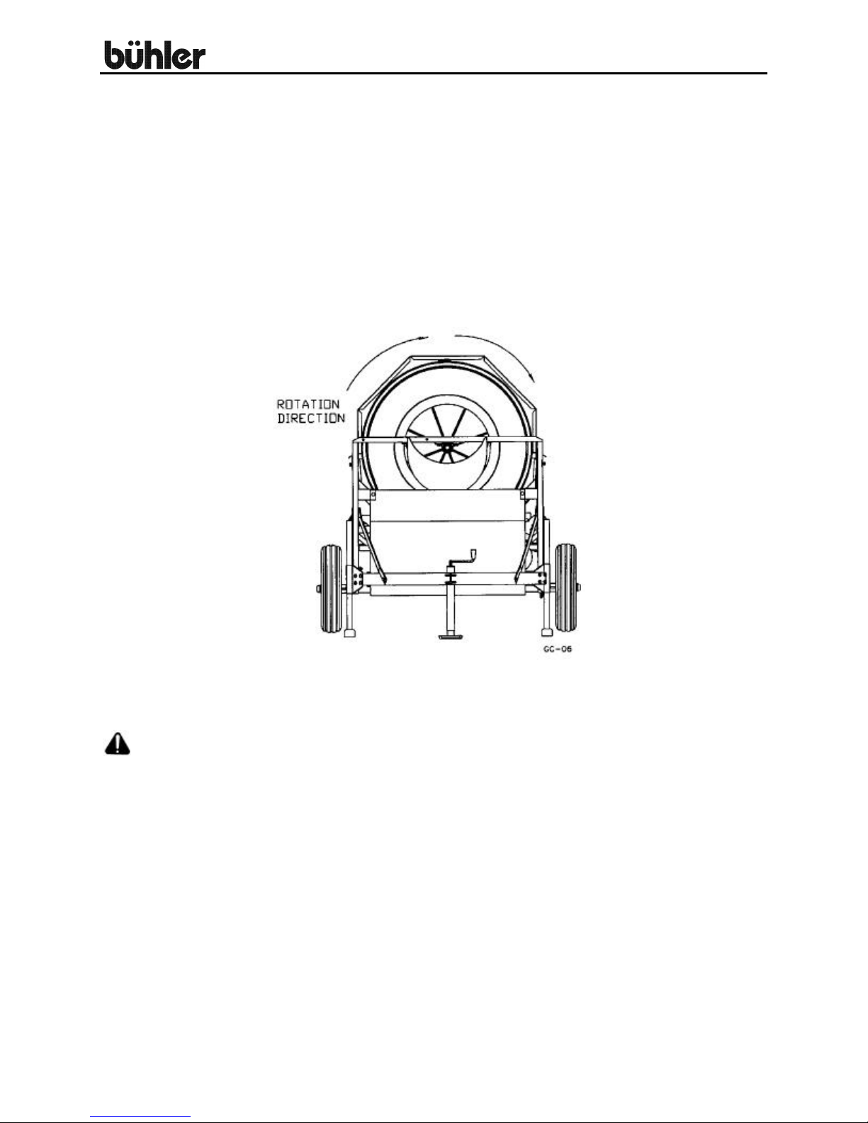
When viewed from the front end (the intake end), the outside drum turns approximately
19 revolutions per minute and rotates clockwise as shown in drawing below.
The jack is used both to hook up the cleaner for transport and to adjust the slope of the
cleaner.
CAUTION: During operation the cleaner should rest on the two adjustable front
legs, not the jack. Adjust the cleaner height to achieve maximum capacity without grain
loss through th e trash chute. The cone flow control must also be adjusted so trash can
get through while minimizing grain loss.
The capacity of the cleaner will vary with the type of grain and moisture content. Adjust
the flow on the intake auger to match cleaner capacity. The cleaner should be run until
empty before stopping. Do not leave grain in cleaner or start the cleaner with a load of
grain on it.
SCREENS
A variety of screens are available to suit your needs. Screens should be mounted so
the lap joints are on one of the screen support bars.
3

#480 Grain Cleaner
MODEL #480 GRAIN CLEANER OPERATING INSTRUCTIONS - CONT'D.
8" x 11' INTAKE AUGER OPTION
An 8" x 11' utility auger is available as an option. A swivel arm to connect the auger to
the cleaner and a cradle for transport are supplied with all cleaners. The utility auger
requires a 2 hp, 1725-RPM electric motor to be supplied by the customer. The utility
auger comes with a flow control so input can be matched to cleaner capacity.
FRAME SIDE PANEL AND TRASH PAN OPTION
A kit consisting of side panels for the frame and a trash pan to catch fines is available
as an option. The trash pan has an auger, which feeds the fines to an opening at one
end of the pan.
SERVICE
Belt tension must be maintained to assure maximum belt lift. Check the belt tension
frequently and remove any trash, which might accumulate in the pulley grooves. If the
cleaner has the trash pan option, be sure to clean out any remaining grain in the trough
to keep it from rotting. When hauling the cl eaner for a long distance, always check the
wheel bolts before leaving.
TOWING
Towing speed should not exceed 45 miles per hour. Use a safety chain when towing on
the highway.
STORAGE
Store the cleaner inside a dry place to prevent deterioration of the belts. Clean
thoroughly before placing in storage.
4
#480 Grain Cleaner
MODEL #480 GRAIN CLEANER ASSEMBLY INSTRUCTIONS
The following instructions refer to the intake end of the cleaner as the front and the
output end as the rear.
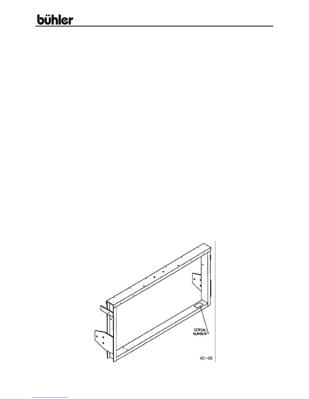
1. (Page 11)
Join the front and rear frame (#1 and #2) together using the frame sides (#3 and
#4) and ½” x 1 ¼” cap screws, lock washers and hex nuts. The right hand frame
(#3) has two extra 5/16" holes, which must be turned so they face up at the front
of the cleaner. The frame ends and sides must be squared before the bolts are
tightened.
2. (Page 11)
Mount the wheels on the axle assembly (#6). The easiest way to mount the axle
under the cleaner is by lifting the frame assembly with a hoist or front end loader
and then bolting on the axle braces (#7 & 8) between the frame sides and the
axle. The front axle brace (#8) has an extra hole 5 ½” from one end which must
be turned facing down. Two frame braces (#10) are bolted to the brace using
this hole. The other end of the brace bolts to the front frame. Use ½” x 1 ¼” cap
screws, lock washers and hex nuts for all the braces.
3. (Page 11)
Bolt the hitch assembly (#5) to the front frame using ½” x 1 ¼” cap screws.
Mount the jack (#13) to the round sleeve on the hitch brace. The jack is used
when hooking up the cleaner for towing and to adjust the slope of the cleaner.
Insert the two front legs (#14) and lock in place using a ½” x 4 ½” pin (#15) and a
spring clip. If the cleaner is purchased with a trash pan, the next step should be
the pan assembly (step #11). These instructions follow the instructions for the
basic cleaner. If there is no pan, continue with step #4.
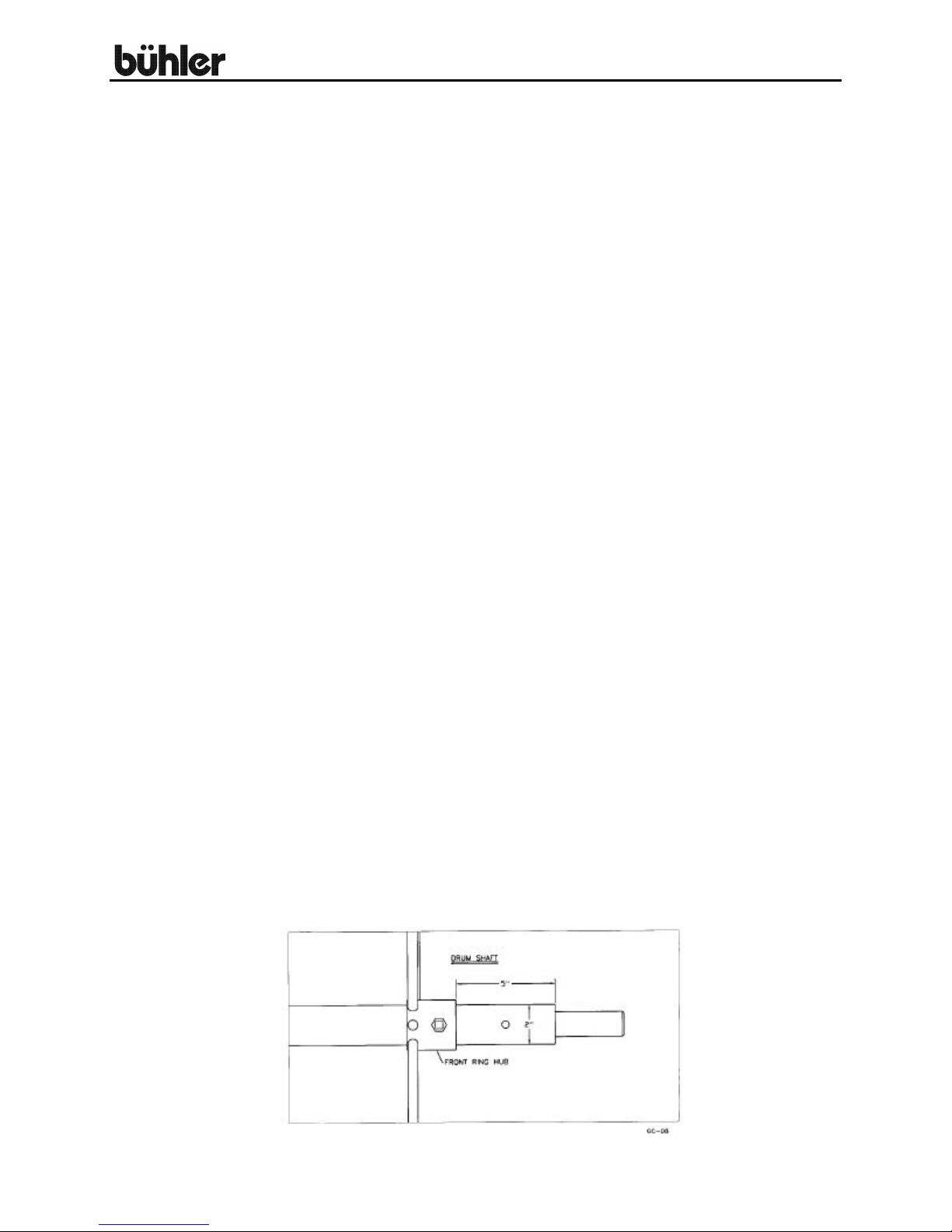
4. (Page 13)
Assemble the cone and drum on the drum shaft (#39) before mounting the
assembly on the grain cleaner frame. The cone assembly inside the drum is
shown at the bottom of the drawing. Check to see that all rings are turned as
shown. The cone sleeve (#36) fits between the rear center drum ring (#34) and
the rear drum ring (#35). Do not forget to slide the cone flow control (#43) and
cone support ring (#42) onto the drum shaft before tightening any rings. Use a
3/8" x ¾” set screw and hex nut to tighten rings. Begin by positioning the front
drum ring (#32) on the drum shaft as shown in the drawing below.
5
#480 Grain Cleaner
MODEL #480 GRAIN CLEANER ASSEMBLY INSTRUCTIONS - CONT'D.
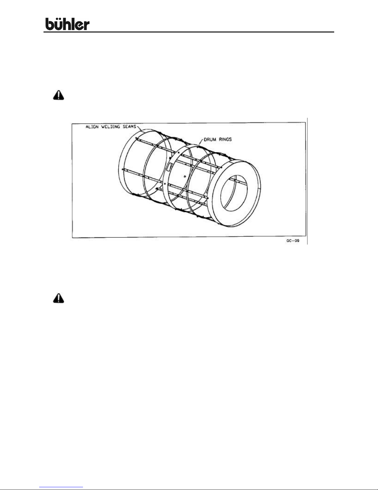
4. Bolt on every other drum support bar (#37) using 5/16" x 1" carriage bolts,
lock washers and hex nuts. This will enable you to align the outside holes
and leave plenty of room to work on the cone inside the drum.
ALERT: The welding seams on the drum rings must all be aligned as shown in
drawing below.
The cone is assembled inside the drum before finishing the outer drum
assembly. Bolt the cone screen supports (#38) inside the cone rings
using 5/16" x 1" carriage bolts, lock washers and hex nuts. Bolt on the
rest of the drum support bars and lock all rings on the drum shaft.
ALERT: Only three of six drum bars have holes for self tapping screws. Space
these with the three without holes.
6
 Loading...