

Buhler 360 User Manual

#360 Grain Cleaner
WARRANTY REGISTRATION AND POLICY
Buhler Manufacturing products are warranted for a period of twelve (12) months from
original date of purchase, by original purchaser, to be free from defects in material and
workmanship under correct, normal agricultural use and proper applications.
Buhler Manufacturing’s obligations under this warranty shall be limited to the repair or
exchange, at Buhler Manufacturing’s option, of any Buhler Manufacturing product or
part which proves to be defective as provided. Buhler Manufacturing reserves the right
to either inspect the product at the buyer’s location or have it returned to the factory for
inspection.
The above warranty does not extend to goods damaged or subject to accident, abuse or
misuse after shipment from Buhler Manufacturing’s factory, nor to goods altered or
repaired by anyone other than an authorized Buhler Manufacturing representative.
Buhler Manufacturing makes no Express Warranties other than those, which are
specifically described. Any description of goods, including any references and
specifications in catalogues, circulars and other written material published, is for the
sole purpose of identifying goods and shall conform to such descriptions. Any sample
or model is for illustrative purposes only and does not create an Express Warranty that
the goods conform to sample or model shown.
The purchaser is solely responsible for determining suitability of goods sold. This
warranty is expressly in lieu of all other warranties expressed or implied. Buhler
Manufacturing will in no event be liable for any incidental or consequential damages
whatsoever. Nor for any sum in excess of the price received for the goods for which
liability is claimed.
WARRANTY CLAIMS:
Warranty requests must be prepared on Buhler Manufacturing Warranty Claim Forms
with all requested information properly completed. Warranty Claims must be submitted
within a thirty (30) day period from date of failure repair.
WARRANTY LABOR:
Any labor subject to warranty must be authorized by Buhler Manufacturing. The labor
rate for replacing defective pa rts, where app licable, will be cre dited at a rate d etermined
by the Company, Buhler Manufacturing.
IMPORTANT FACTS:
Buckets and Bucket Tines Carry No Warranty
Bent Spears Carry No Warranty
Snowblower Fan Shafts Carry No Warranty
Mower Blades Carry No Warranty
Portable Auger Parts Have Two (2) Year Warranty
- 1 -
#360 Grain Cleaner
SAFETY INSTRUCTIONS
1. Read and understand the operator’s manual before operating.
2. Keep all safety shields and devices in place.
3. Make certain everyone is clear before operating or moving the machine.
4. Keep hands, feet and clothing away from moving parts.
5. Shut off power to adjust, service or clean.
6. Tow the cleaner only at low speeds (approx. 20 mph)
7. Use a slow moving vehicle sign and warning lights if it is necessary to
move the cleaner on a roadway.
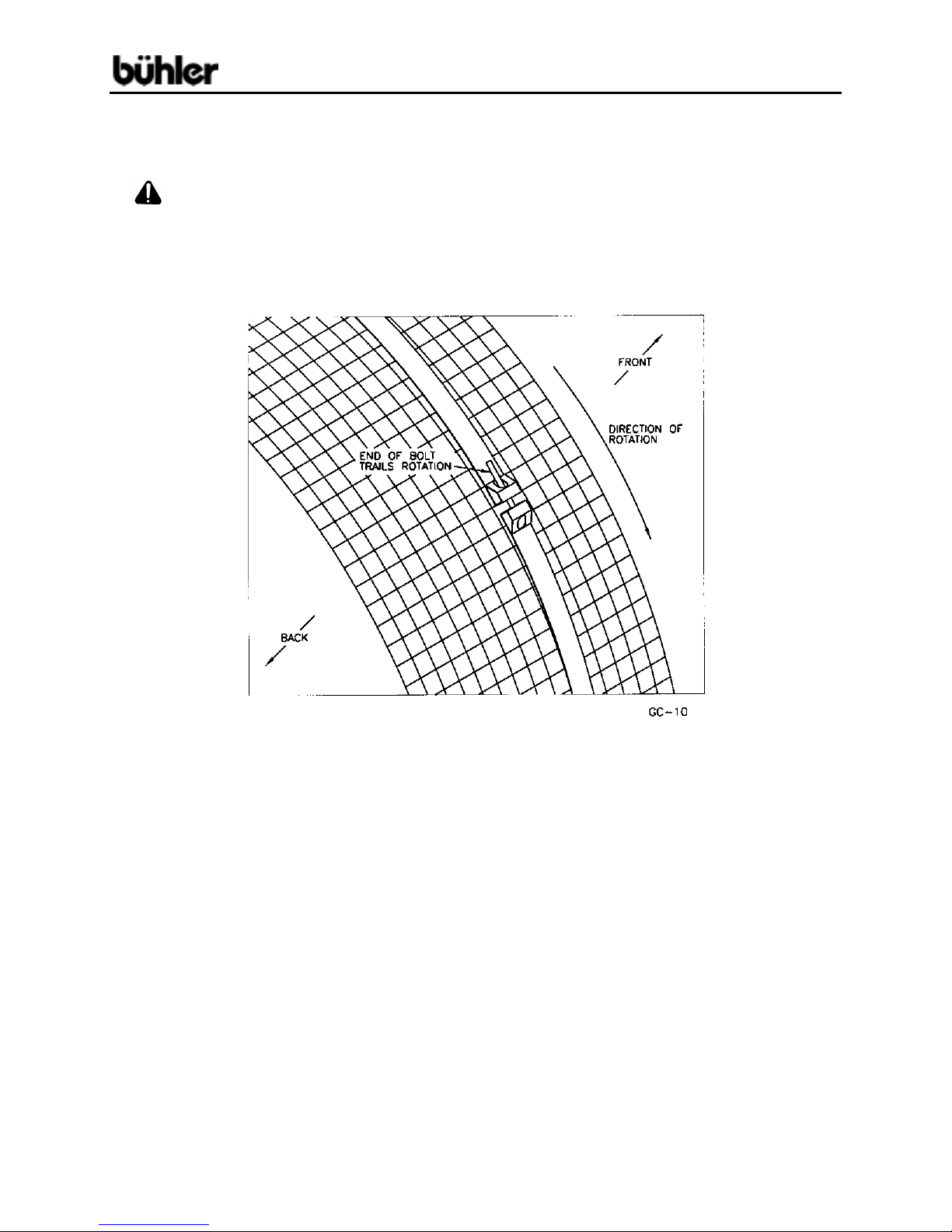
8. The bolts which clamp on the drum screen straps should be turned so the
end of the bolt trails the direction of rotation as explained in the assembly
instructions.
9. Disconnect power before resetting motor overload.
10. Make certain electric motors are grounded.
- 2 -

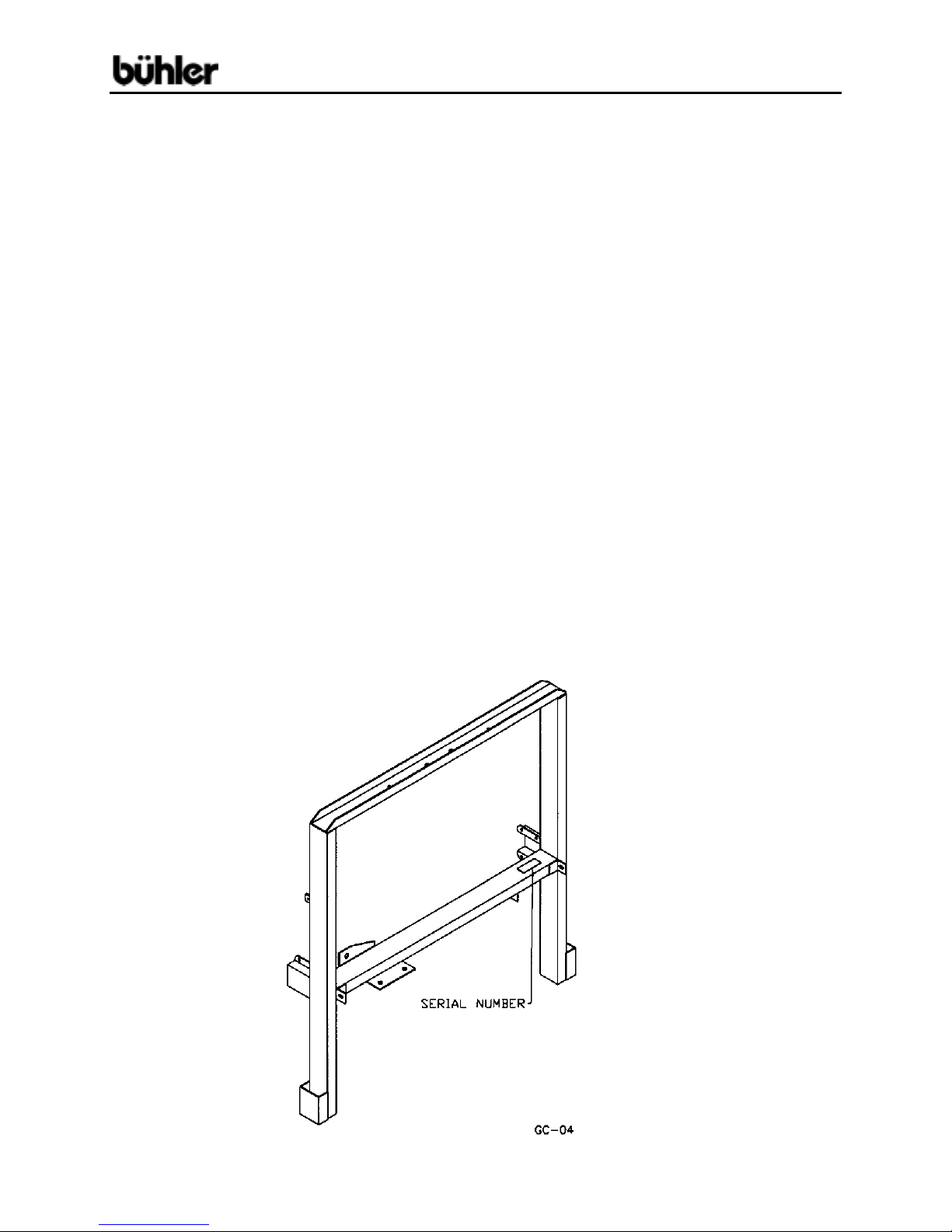
#360 Grain Cleaner
MODEL #360 GRAIN CLEANER ASSEMBLY INSTRUCTIONS
ALERT: The following instructions refer to the intake end of the cleaner as the
front and the output end as the rear.
1. Join the front frame (#1) and rear frame (#2) with two frame sides (#3) using four
frame clamp plates (#6) with 5/16" x ¾” cap screws, lock washers and hex nuts.
Bolt the frame cross brace (#4) between the frame sides using two frame clamps
(#5). The hitch (#7) is pushed through the holes in the rear frame and frame
cross brace and fastened to the frame cross brace with a 3/8" x 4" cap screw and
lock nut. The hitch length is adjusted by moving the position of the frame cross
brace.
CAUTION: All bolts connecting the fame must be firmly tightened. Any loose
bolts could result in the frame separating while towing the cleaner.
2. Slide the front legs (#11) into the sleeves at the bottom of the front frame.
A 3/8" x 2" cap screw, lock washer and hex nut through each leg is used to
adjust the height of the front of the cleaner. Place a wheel spacer (#12) on the
stub shafts and mount the wheels (#13). The wheels are held on by a 1" I.D. flat
washer and a ¼” x 1 ½” cotter pin. A 5/16" x ¾” cap screw, lock washer and hex
nut is bolted through one of the holes at the top of the leg to keep it from sliding
out.
3. Mount two 1" pillow bearings (#16) on the reducer shaft (#18) and bolt the
bearings to the bottom of the reducer mount welded to the front frame as shown
in drawing. Use ½” x 1 ¾” cap screws, lock washers and hex nuts. Bolt the idler
arm (#25) to the same reducer mount using a 5/8" x 1 ¾” cap screw and lock nut.
The end of the idler arm with the small hole is turned to the outside of the frame.
Mount the idler pulley (#24) to the other end of the idler arm. A 5/8" I.D. flat
washer is placed between the idler pulley and the idler before tightening with a
5/8" jam nut. A 3" pulley (#19) is mounted on the inside of the reducer shaft and
a 15" pulley (#26) is mounted on the outside.
4. Bolt the motor mount (#33) to the front frame with two motor mount clamps (#34)
using 3/8" x 1" cap screws, lock washers and hex nuts. The tightener hole in the
side of the motor mount must face the tightener bracket welded to the front
frame. Connect the belt tightener rod (#35) between the motor mount and the
welded bracket on the frame using two 3/8" hex nuts. Bolt the motor guard (#32)
and 1 H.P. electric motor (not supplied) to the motor mount using 5/16" x 1" cap
screws, lock washers, flat washers and hex nuts. Mount a 2 ½” pulley (#29) on
the electric motor and connect this pulley and the 15" pulley (#26) with a B-62
V-belt (#28). Tighten belt using belt tightener rod (#35).
- 3 -

#360 Grain Cleaner
MODEL #360 GRAIN CLEANER ASSEMBLY INSTRUCTIONS – cont’d.
5. Assemble the three drum rings (#'s 67, 68, & 69); cone flow control (#76) and two
drum screen support rings (#71) on the drum shaft (#70). The cone flow control
comes between the front and center drum rings while the drum screen support
rings are placed on each side of the center drum ring. Be certain that all three
drum rings are turned as shown in drawing. Support the ends of the drum shaft
on stands so the rings can be turned till the outer holes in all three rings and the
screen support rings are aligned. The holes for the cone screen support bars
(#73) should also be aligned when the outer holes in the drum rings are in line.
6. The six cone screen support bars (#73) are bolted between the front and center
drum rings to form a cone. Use 5/16" x ¾” cap screws, lock washers and hex
nuts at the center ring and 5/16" x ¾” carriage bolts, lock washers and hex nuts
at the front ring. Join the three drum rings and the two screen support rings with
six drum screen support bars (#72) using 5/16" x ¾” carriage bolts, lock washers
and hex nuts. Do not tighten any nuts until all bolts are in place. Lock the drum
rings and the cone flow control onto the drum shaft by inserting a 3/8" x 1" set
screw into the hubs and tightening.
7. Mount 1" pillow bearings (#16) on each end of the drum shaft. Lift the drum
assembly into the frame with the cone end towards the front frame (end with
adjustable legs). Bolt the rear pillow bearing to the top of the rear frame using
½” x 1 ¾” cap screws, lock washers, flat washers and hex nuts. Bolt the front
pillow bearing underneath the top cross brace of the front frame. The intake
auger pivot (#36) is placed on the top side of the same cross brace and bolted on
together with the bearing using ½” x 2" cap screws, lock washers, flat washers
and hex nuts. Place the B-133 V-belt (#22) around the front end of the drum
before bolting on the front bearing. The rear drum ring should be positioned with
1 ¼” gap to the rear frame to allow clearance at the front end.
8. Mount the drum belt on the 3" pulley (#19) at the inside of the reducer shaft
(#18). Tighten the belt with the idler pulley (#24) by hooking one end of the belt
tightener spring (#23) in the end of the idler arm (#25) and the other end in the
bracket welded to the inside edge of the front frame.
CAUTION: Spring may be unhooked while installing drum screen to allow
easier rotation of drum.
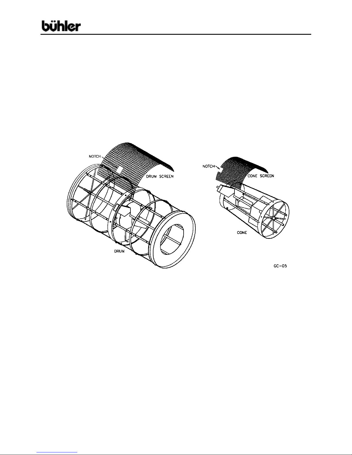
9. Mount the three cone screen sections (#75). Two of the cone segments will have
to be notched to fit around the trash outlets on the center ring (see drawing
below). After fitting the cone segments, pin them to the cone with ¼” x ¾” selftapping screws and flat washers. Strap the ends of the cone screens to the front
and center rings using the two cone straps (#'s 77, & 78). Tighten straps with ¼”
x 2 ½” round head bolts and ¼” square nuts. After strapping, the screen is
tightened by inserting the remaining self-tapping screws.
- 4 -
#360 Grain Cleaner
MODEL #360 GRAIN CLEANER ASSEMBLY INSTRUCTIONS – cont’d.
CAUTION: All the strap bolts holding the drum screens should be turned so
the end of the bolt trails the direction of rotation as shown in the drawing. This is
done so the end of the bolt will not accidentally hook onto your hand or clothing
while the drum is rotation.
- 5 -
#360 Grain Cleaner
MODEL #360 GRAIN CLEANER ASSEMBLY INSTRUCTIONS – cont’d.
Both drum screens must also be notched to fit around the trash outlets as shown
in the drawing below. A convenient way to hold the screen in position during
assembly is by hooking several small springs across the lap joint. Two springs to
hold the screen in place (#87) are included in the bag with each cleaner. After
notching, pin the screens to the outer drum with ¼” x ¾” self-tapping screws and
flat washers. Before fastening screen, be sure that the screen is flat against the
drum rings and the screen supports all the way around the drum. Straps (#77)
are fastened around the screens at the front and back rings, on each side of the
trash outlets on the center ring and around each of the drum screen support rings
(#71). Tighten straps and insert the remaining self-tapping screws.
10. Insert the discharge pan (#8) into the rear fra me betw een the fra me sides and
the top and center cross braces. Bolt to frame sides using ¼” x 2" cap screws,
lock washers, flat washers and hex nuts. Fasten top edge of discharge pan to
the top cross brace on the rear frame using ¼” x ¾” self-tapping screws. Fit the
rear drum shield (#9) around the rear of the drum and fasten to the top of the rear
frame using ¼” x ¾” self-tapping screws. The rear drum shield is also bolted to
the discharge pan using ¼” x ¾” cap screws, lock washers and hex nuts. Mount
the pulley guard (#17) to the front frame by bolting it to the angle irons welded to
the ends of the center cross brace using 5/16" x ¾” cap screws, lock washers,
flat washers and hex nuts. Fasten the intake pan (#10) under the top cross
brace of the front frame using 3/8" x ¾” cap screws, lock washers and hex nuts.
11. Intake Auger (Optional)
Insert the intake auger swivel (#37) into the intake auger pivot (#36), which is
already bolted to the top of the front frame. Bolt the intake auger connector plate
(#40) to the intake auger using 3/8" x ¾” cap screws, lock washers and hex nuts.
Join the intake auger connector plate and the intake auger swivel with a
½” x 7 ½” pin (#38) and cotter pin.
- 6 -
 Loading...