

Buhler 2180 User Manual

Buhler
Versatile
2145
2160
2180
2210
Genesis II
89007102 01/06

TO THE OWNER:
The warranty coverage that is extended to your tractor is explained in the Warrantyand Limitation of Liability form.
Your dealer will provide you with a copy of the warranty and retain a copy which y ou have signed. After you read
the warranty, ask your dealer to explain any points that you may not understand.
This tractor was designed to power and propel itself. It is intended for use in normal and customary agricultural
applications.
Do not modify or alter or permit anyone else to modify or alter this tractor or any of its components or any tractor
function without first consulting an authorized Buhler Versatile dealer. If you have any questions regarding tractor
modifications, contact Buhler Versatile Inc., 1260 Clarence Avenue, Winnipeg, MB R3C 4E8
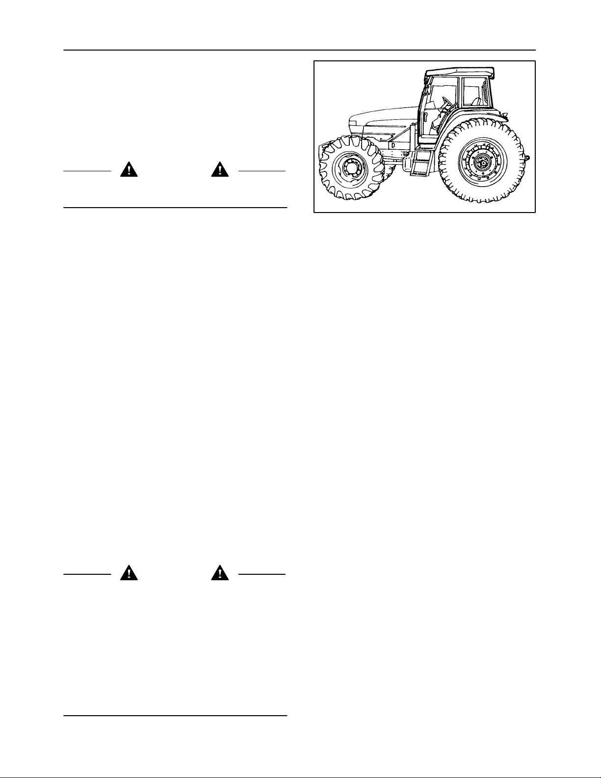
A safety cab incorporating a Roll Over Protection Structure (ROPS) and a seat belt were standard equipment
for the tractor at the time of factory assembly. If the safety cab/ROPS has been modified or removed by the original purchaser, it is recommended that you equip your tractor with a safety cab/ROPS and seat belt. A safety
cab/ROPS is effective in reducing injuries during tractor overturn accidents. Overturning a tractor without a
ROPS can result in serious injury or death. Safety cab/ROPS and seat belts are available for your tractor. If your
tractor is not equipped with a safety cab/ROPS and seat belt, see your Buhler Versatile dealer.
Your safety and the safety of those around you depends upon the care and good judgment you use while operating this equipment. Read the safety precautions carefully.
For a complete list of the delivery service checks performed by your dealer, refer to DELIVERY REPORT in this
manual. The first copy is your record of the service performed and the second copy, which is to be removed from
the manual, is your dealer’s record. MAKE SURE THAT YOU AND THE DEALER SIGN BOTH COPIES.
After you have operated the tractor for 50 hours, take your tractor and this manual to your selling dealer. He w ill
perform the factory recommended 50-hour service. You will be responsible for the cost of lubricants, fluids, filters
and other items replaced as part of normal maintenance. Prior to taking the tractor to your selling dealer for service, it is recommended that you contact them to determine any other charges for which you may be responsible.
All data given in this book is subject to production variations. Dimensions and weights are approximate only and
the illustrations do not necessarily show tractors in standard condition. For exact information about any particular
tractor please consult your Buhler Versatile dealer.
CAUTION
This symbol is used throughout this book whenever personal safety is involved. Take time to read and
follow the instructions. Be careful!
Pictures in this manual may show protective shielding open or removed to better illustrate a particular
feature or adjustment.
Be certain, however, to close or replace all shielding before operating the machine.
IMPROVEMENTS
Buhler Versatile Inc. is continually striving to improve its products. We reserve the right to make improvements
or changes when it becomes practical and possible to do so, without incurring any obligation to make changes
or additions to the equipment sold previously.

CALIFORNIA EMISSION CONTROL WARRANTY STATEMENT
YOUR WARRANTY RIGHTS AND OBLIGATIONS
The California Air Resources Board and Buhler Versatile are pleased to explain the emission control system warranty on your engine. In California, new 1996 and later heavy-duty off-road engines from 175 to 750 HP must be designed, built, and equipped to meet the State’s stringent
anti-smog standards. Buhler Versatile must warrant the emission control system on your engine for the periods of time listed below, provided
there has been no abuse, neglect, or improper maintenance of your engine.
Your emission control system includes parts such as the fuel injection system and the air induction system.
Where a warrantable condition exists, Buhler Versatile will repair your heavy-duty off-road engine at no cost to you, including diagnosis, parts,
and labor.
Manufacturer’s Warranty Coverage:
The 1996 and later heavy-duty off-road engines are warranted from the original date of delivery for five years or 3,000 hours of operation,
whichever occurs first. If any emission -related part on your engine is defective, the part will be repaired or replaced by Buhler Versatile.
Owner’s Warranty Responsibilities:
D As the heavy-duty off-road engine owner, y ou are responsible for the performance of the required maintenance listed in your owner’s
manual. Buhler Versatile recommends that you retain all receipts covering maintenance on your heavy-duty off-road engine, but Buhler
Versatile cannot deny warranty solely for the lack of receipts or for your failure to ensure the performance of all scheduled maintenance.
D As the heavy-duty off-road engine owner, you should, however, be aware that Buhler Versatile may deny you warranty coverage if your
heavy-duty off-road engine or a part has failed due to abuse, neglect, improper maintenance, or unapproved modifications.
D Your engine is designed to operate on commercially available diesel fuel only. Use of any other fuel may result in your engine no longer
operating in compliance with California’s emissions requirements.
D You are responsible for initiating the warranty process. The ARB suggests that you present your heavy-duty off-road engine to a Buhler
Versatile dealer as soon as a problem exists. The warranty repairs should be completed by the dealer as expeditiously as possible.
If you have questions regarding your warranty rights and responsibilities, you should contact the Buhler Versatile Warranty Department.
D Prior to the expiration of the warranty, you must give notice of any failure of an emission control warranted part. Such notice must be
given to Buhler Versatile or an authorized dealer, and you must deliver the engine to the repair location.
D You, the owner,are responsible for incidental costs incurred by yourself or your employees as a result of a warrantable failure. Examples
of such costs are communication expenses, meals and lodging.
D The owner is responsible for any business costs or losses, any “downtime” expenses and any “cargo” damage which result from the
failure of a warranted part. Buhler Versatile is not responsible for other incidental or consequential damages, including but not limited
to fines, theft, vandalism or collisions.
Parts covered:
This emission control system warranty applies to the following 675TA/KA emission control parts.
Fuel Injection Pump
Fuel Injectors
Turbocharger
Intake Manifold
Charge Air Cooler
Exhaust Manifold
Any replacement part, equivalent in performance and durability, may be used in the performance of any maintenance or repairs and must
be provided without charge to the owner. The use of these parts does not reduce the warranty obligations of Buhler Versatile. However,Buhler
Versatilerecommends the use of new, genuine Buhler Versatile service parts or Buhler Versatile approved rebuilt parts and assemblies. Buh ler Versatile also recommends that the engine be serviced by a Buhler Versatile authorized dealer.
Buhler Versatile Responsibilities
Warranty work will be provided at no charge to the owner at any authorized dealer, using new genuine Buhler Versatile service parts or Buhler
Versatile approved rebuilt parts or assemblies..
The owner will not be charged for diagnostic labor which leads to the deter mination that a warranted part is defective, if the diagnostic work
was performed at a warranty station.
Buhler Versatile is liable for damages to other engine components caused by the failure under warranty of any warranted part.
Warranty Limitations
Buhler Versatile is not responsible for failures resulting from abuse or neglect by owner or operator.
Buhler Versatile warrants to the ultimate purchaser and each subsequent purchaser that the engine is designed, built, and equipped so as
to conform with all applicable regulations adopted by the Air Resources Board, and that it is free from defects in materials and workmanship
which cause the failure of a warranted part.
Any warranted part which is not scheduled for replacement as required maintenance, or which is scheduled only for regular inspection to
the effect of “repair or replace as necessary” is warranted for the warranty period.
Any warranted part which is scheduled for replacement as required maintenance is warranted for the period of time prior to the first scheduled
replacement point for that part.
Buhler Versatile is liable for damages to other engine components caused by the failure under warranty of any warranted part.
0-1

SECTION 0 -- SAFETY
FEDERAL EMISSIONS WARRANTY
Buhler Versatile warrants that your new 2003 and later heavy-duty off-road diesel engine was designed, built, and equipped to conform to
applicable U.S. Environmental Protection Agency regulations for a period of use of five years or 3,000 hours of operation, whichever occurs
first.
The new model year, class of diesel engine, and emission application determination for your engine are identified on the emission control
information label affixed to the top of your engine’s rocker arm cover. The warranty period begins on the date the new equipment is sold to
the first retail purchaser.
Any emission control system parts which are proven defective during normal use will be repaired or replaced during the warranty period. The
warranty repairs and service will be performed by any authorized Buhler Versatile dealer at the dealer’s place of business, with no charge
for parts or labor (including diagnosis).
As the engine owner, you are responsible to perform all the required maintenance listed in your owner’s manual. Buhler Versatile will not deny
an emission warranty claim solely because y ou have no record of maintenance; however, a claim may be denied if your failure to perform
maintenance resulted in the failure of a warranted part. Receipts covering regular maintenance should be retained in the event of questions
and these receipts should be passed on to each subsequent owner of the engine.
It is recommended replacement parts used for maintenance or repairs be Buhler Versatile Service Parts to maintain the quality originally
designed into your emission certified engine. The use of non-Buhler Versatile parts does not invalidate the warranty on other components
unless the use of such parts causes damage to warranted parts.
Buhler Versatile wishes to assure the emission control systems warranty is being properly administered. If you believe you have not received
the service entitled to under this warranty, you should contact the Buhler Versatile Service Department.
Service Department
Buhler Versatile Inc.
1260 Clarence Avenue, Box 7300
Winnipeg, MB R3C 4E8
(204) 284--6100
Please note that the Emission Warranty does not cover:
1. Systems and parts that were not first installed on the new equipment or engine as original equipment by Buhler Versatile.
2. Part malfunctions caused by abuse, misuse, improper adjustment, modification, alteration, tampering, disconnection, improper or
inadequate maintenance, or use of non-recommended fuels and lubricating oils.
3. Accident caused damage, acts of nature, or other events beyond Buhler Versatile’s control.
4. Replacement of expendable items made in connection with scheduled maintenance.
5. Parts requiring replacement, inspection or adjustment maintenance intervals for reasons other than being defective.
6. Parts which are not Buhler Versatile Service Parts.
7. Loss of time, inconvenience, loss of use of equipment/engine or commercial loss.
8. Equipment with altered or disconnected hourmeter where the hours cannot be determined.
9. Equipment normally operated outside the United States.
10. Non-defective parts replaced by other than Buhler Versatile dealers.
Coverage
This emission control system warranty applies to the following 675TA/** emission control parts.
Fuel Injection Pump
Fuel Injectors
Turbocharger
Intake Manifold
Charge Air Cooler
Exhaust Manifold
0-2

SECTION 0 -- SAFETY
CONTENTS
SAFETY 0-4........................................................
GENERAL INFORMATION 1-1.......................................
OPERATION 2-1...................................................
LUBRICATION AND MAINTENANCE 3-1..............................
TROUBLESHOOTING 4-1...........................................
SPECIFICATIONS 5-1..............................................
INDEX 5-27.........................................................
DELIVERY REPORT 5-31............................................
SERVICE REPORTS 5-40.............................................
0-3

SECTION 0 -- SAFETY
PRECAUTIONARY STATEMENTS
PERSONAL SAFETY
Throughout this manual and on machine decals, you will find precautionary statements (“CAUTION”,
“WARNING”,and “DANGER”) followed by specific instructions. These precautions are intended for the personal
safety of you and those working with you. Please take the time to read them.
CAUTION
The word “CAUTION” is used where a safe behavioral practice according to operating and maintenance
instructions and common safety practices will protect the operator and others from accident
involvement.
WARNING
The word “WARNING” denotes a potential or hidden hazard which has a potential for serious injury. It
is used to warn operators and others to exercise every appropriate means to avoid a surprise
involvement with machinery.
DANGER
The word “DANGER” denotes a f orbidden practice in connection with a serious hazard.
FAILURE TO FOLLOW THE “CAUTION”, “WARNING”, AND “DANGER” INSTRUCTIONS MAY RESULT IN
SERIOUS BODILY INJURY OR DEATH.
MACHINE SAFETY
Additional precautionary statements (“ATTENTION” and “IMPORTANT”) are followed by specific instructions.
These statements are intended for machine safety.
ATTENTION: Theword“ATTENTION” is used to warn the operator of potential machine damage if a certain
procedure is not followed.
IMPORTANT: Theword“IMPORTANT” is used to inform the reader of something he needs to know to prevent
minor machine damage if a certain procedure is not followed.
0-4

SECTION 0 -- SAFETY
0-5

SECTION 0 -- SAFETY
SAFETY PRECAUTIONS
A careful operator is the best operator. Most
accidents can be avoided by observing certain
precautions. To help prevent accidents, read and
take the following precautions before operating
the tractor. Equipment should be operated only
by those who are responsible and instructed to
do so.
THE TRACTOR
1. Read the Operator’s Manual carefully before
using the tractor. Lack of operating knowledge can lead to accidents.
2. Only allow properly trained and qualified
persons to operate the tractor.
3. To prevent falls, use the assist rails and step
plates when getting on and off the tractor.
Keep steps and platform clear of mud and
debris.
4. Do not permit anyone but the operator to ride
on the tractor. There is no safe place for extra
riders.
5. Replace all missing, illegible or damaged
safety decals.
6. Keep safety decals free of dirt or grime.
7. Do not modify or alter or permit anyone else
to modify or alter the tractor or any of its
components or any tractor function without
first consulting an authorized dealer.
8. Install all shields before starting or operating
the tractor.
DRIVING THE TRACTOR
1. Always sit in the driver’s seat while starting
or driving the tractor.
2. When driving on public roads, have consideration for other road users. Pull to the side of
the road so that any following traffic may
pass.
3. Dim the tractor lights when meeting a vehicle
at night. Make sure the lights are adjusted to
prevent blinding the driver of an oncoming
vehicle.
4. Reduce speed before turning or applying the
brakes. Lock the brake pedals together when
travelingatroadspeedsorwhenonthe
highway. Brake both wheels simultaneously
when making an emergency stop.
5. Use extreme caution and avoid hard application of the tractor brakes when towing heavy
loads at road speeds.
6. Any towed vehicle whose total weight
exceeds that of the towing tractor must be
equipped with brakes for safe operation.
7. Never apply the differential lock when
turning. When engaged, the differential lock
will prevent the tractor from turning.
8. Always check overhead clearance, especially when transporting the tractor.Watch where
you are going, especially at row ends, on
roads and around trees and low overhanging
obstacles.
9. Use extreme caution when operating on
steep slopes.
10. To avoid overturns, drive the tractor with care
and at speeds compatible with safety,
especially when operating over rough
ground, when crossing ditches or slopes and
when turning corners.
11. If the tractor becomes stuck or the tires are
frozen to the ground, engage a reverse gear
to free the tractor and prevent overturning.
12. Keep the tractor in the same gear when going
downhill as would be used when going uphill.
Do not coast or freewheel down hills.
0-6

SECTION 0 -- SAFETY
OPERATING THE TRACTOR
1. Apply the parking brake, place the PTO
control in the “OFF” position, the lift control
lever in the down position, the remote control
valve levers in the neutral position and the
transmission lever in neutral before starting
the tractor.
2. Do not start the engine or operate controls
(other than the external hydraulic lift
switches) while standing beside the tractor.
Always sit in the tractor seat when starting
the engine or operating the controls.
3. Do not bypass the transmission neutral start
switch. Consult your authorized dealer if
your neutral start controls malfunction. Use
jumper cables only in the recommended
manner. Improper use can result in a tractor
runaway.
4. Avoid accidental contact with the gear shift
lever while the engine is running. Unexpected tractor movement can result from
such contact.
5. Do not get off the tractor while it is in motion.
6. Shut off the engine and PTO and apply the
parking brake before getting off the tractor.
7. Do not park the tractor on a steep incline.
8. Do not operate the tractor engine in an
enclosed building w ithout adequate ventilation. Exhaust fumes can cause death.
9. The cab air filter is designed to remove dust
from the air but will not exclude chemical
vapor. Follow the chemical manufacturers
directions regarding protection from dangerous chemicals.
10. Always wear a protective mask when working
with toxic spray chemicals. Follow the
directions on the chemical container.
11. If the power steering or engine ceases to
operate, stop the tractor immediately as the
tractor will be more difficult to control.
13. Tighten all connections before starting the
engine or pressurizing lines.
14. Pull only from the swinging drawbar. Use
only a drawbar pin that locks in place. Pulling
from the tractor rear axle or any point above
the axle may cause the tractor to overturn.
15. If the front end of the tractor tends to rise
when heavy implements are attached to the
three-point hitch, install front end weights.
Do not operate the tractor with a light front
end.
16. Always select Position Control when attaching equipment and when transporting equipment. Be sure hydraulic couplers are
properly mounted and will disconnect safely
in case of accidental detachment of the
implement.
17. Do not leave equipment in the raised position
when the vehicle is stopped or unattended.
18. Ensure any attached equipment or accessories are correctly installed, are approved for
use with the tractor, do not overload the
tractor and are operated and maintained in
accordance with the instructions issued by
the equipment or accessory manufacturer.
19. Remember that your tractor, if abused or
incorrectly used, can be dangerous and
become a hazard both to the operator and to
bystanders. Do not overload or operate with
attached equipment which is unsafe, not
designed for the particular task or is poorly
maintained.
20. The cab is designed to provide the minimum
noise level at the operator’s ears and, in fact,
meets or exceeds applicable standards in
this respect. However,noise (sound pressure
level) in the workplace can exceed 86dB(A)
when working between buildings or in
confined spaces, when the cab windows are
open. Therefore, it is recommended that the
operators wear suitable ear protectors when
operating in high noise level conditions.
12. Stop the engine and relieve pressure before
connecting or disconnecting hydraulic,
steering or fuel lines.
0-7

SECTION 0 -- SAFETY
OPERATING THE PTO
1. When operating PTO-driven equipment, shut
off the engine and wait until the PTO stops
before getting off the tractor and disconnecting the equipment.
2. Do not wear loose c lothing when operating
the power take-off or when near rotating
equipment.
3. When operating stationary PTO-driven
equipment, always apply the tractor parking
brake and block the rear wheels front and
back.
4. To avoid injury, do not clean, adjust, unclog
or service PTO driven equipment when the
tractor engine is running.
5. Make sure the PTO master shield is in
position at all times a nd always replace the
PTO cover when the PTO is not in use.
SERVICING THE TRACTOR
Most accidents can be avoided by observing
certain precautions. To help prevent accidents,
read and take the following precautions before
servicing the tractor.
1. The cooling system operates under pressure
which is controlled by the radiator cap. It is
dangerous to remove the cap while the
system is hot. Always turn the cap slowly to
the first stop and allow the pressure to
escape before removing the cap entirely.
2. Do not smoke while refuelling the tractor.
Keep any type of open flame away. Wait for
the engine to cool before refuelling.
5. Do not attempt to service the air conditioning
system. It is possible to be severely frost
bitten or injured by escaping refrigerant.
Special equipment and instruments are
required to service the air conditioning
system. See your authorized dealer for
service.
6. Stop the engine before performing any
service on the tractor.
7. Escaping diesel/hydraulic fluid under pressure can penetrate the skin causing serious
injury.
• DO NOT use your hand to check for leaks.
Use a piece of cardboard or paper to
search for leaks.
• Stop the engine and relieve pressure
before connecting or disconnecting
lines.
• Tighten all connections before starting
the engine or pressurizing lines.
• If fluid is injected into the skin, obtain
medical attention immediately or gangrene may result.
8. Do not modify or alter or permit anyone else
to modify or alter the tractor or any of its
components or any tractor function without
first consulting an authorized dealer.
9. The fuel oil in the injection system is under
high pressure and can penetrate the skin.
Unqualified persons should not remove or
attempt to adjust a pump, injector nozzle or
any other part of the fuel injection system.
Failure to follow these instructions can result
in serious injury.
3. Keep the tractor and equipment, particularly
brakes and steering, maintained in a reliable
and satisfactory condition to ensure your
safety and comply with legal requirements.
4. To prevent fire or explosion, keep open
flames away from battery or cold weather
starting aids. To prevent sparks which could
cause explosion, use jumper cables according to instructions.
10. Continuous long term contact with used
engine oil may cause skin cancer. Avoid
prolonged contact with used engine oil.
Wash skin promptly with soap and water.
11. Tractor wheels are very heavy. Handle with
care and ensure, when stored, that they
cannot fall and cause injury.
12. Dispose of all drained fluids and removed
filters properly.
0-8

SECTION 0 -- SAFETY
DIESEL FUEL
1. Under no circumstances should gasoline,
alcohol or blended fuels be added to diesel
fuel. These combinations can create an
increased fire or explosive hazard. In a
closed container such as a fuel tank, these
blends are more explosive than pure
gasoline. Do not use these blends.
2. Ignition switch to OFF position.
3. Never remove the fuel cap or refuel with the
engine running. Allow the tractor to cool off
before fueling.
4. Do not smoke while refuelling the tractor or
when standing near fuel. Keep any type of
open flame away.
5. Use the proper fuel transfer hose and nozzle.
Make sure the nozzle and hose are grounded
to dissipate static electric charges.
6. When refueling, make sure the nozzle is in
contact with the filler neck of the tractor fuel
tank before fuel starts to flow and during the
entire time fuel is flowing.
7. Maintain control of the fuel filler pipe nozzle
when filling the tank.
8. Do not fill the fuel tank to capacity. Allow
room for expansion.
9. Wipe up spilled fuel immediately.
10. Always tighten the fuel tank cap securely.
12. Keep equipment clean and properly maintained.
13. Do not drive equipment near open fires.
14. Never use fuel for cleaning purposes.
15. Arrange fuel purchases so that summer
grade fuels are not held over and used in the
winter.
16. Never operate electrical or electronic equipment (such as cell phones) while around fuel
or while refueling.
SAFETY CAB
Your tractor is equipped with a safety cab which
must be maintained in a serviceable condition.
Be careful when driving t hrough doorways or
working in confined spaces with low headroom.
1. Do not modify, drill, weld or alter the safety
cab in any way. Doing so could render you
liable to legal prosecution in some countries.
2. Never attempt to straighten or weld any part
of the main frame or retaining brackets which
have suffered damage. By doing so you may
weaken the structure and endanger your
safety. Replace all damaged parts.
3. Do not secure any parts on the main frame or
attach your safety cab with other than the
special high tensile bolts and nuts specified.
4. Never attach chains or ropes to the cab or
main frame for pulling purposes.
11. If the original fuel tank cap is lost, replace it
with a genuine replacement cap. A non-approved cap may not be safe.
5. Never take unnecessary risks even though
your safety cab affords you the maximum
protection possible.
0-9
SECTION 0 -- SAFETY
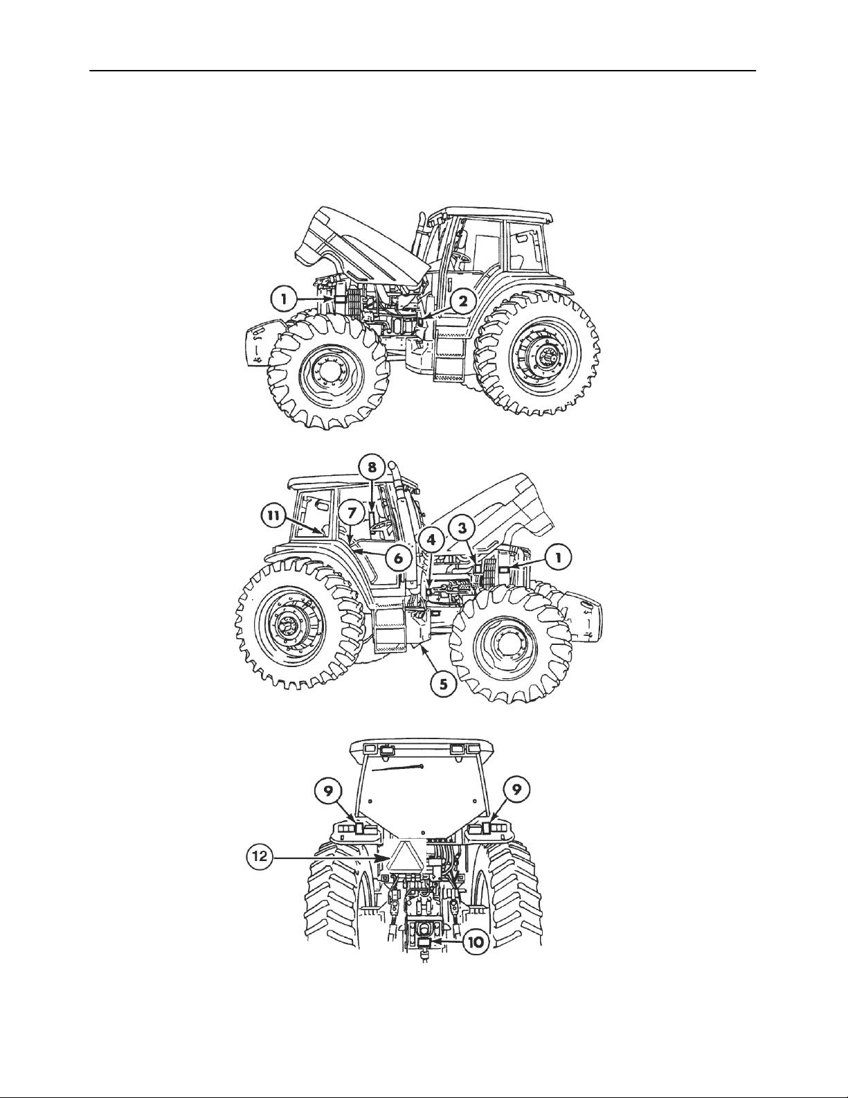
SAFETY DECALS
The following decals were installed on the tractor in
the areas indicated. They are intended for your
safety and for those working with you. Please take
this manual and walk around your tractor to note the
content and location of these decals.
Review these decals and the operating instructions
detailed in this manual with the machine operators.
Keep the decals legible. If they are not, obtain
replacements from your authorized dealer.
0-10
SECTION 0 -- SAFETY
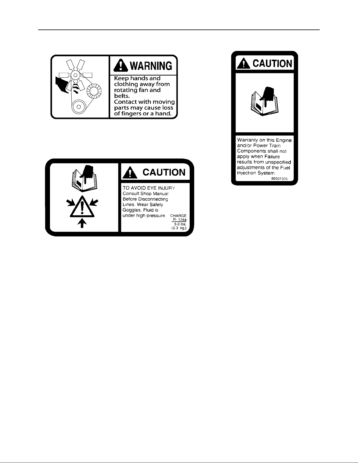
86501511
1. Location : Right and left side of radiator support
86501508
2. Location : Inside left engine access door
3. Location : Engine air cleaner
support on the right side above
the alternator.
0-11
4.
b
Location : Starter motor
SECTION 0 -- SAFETY
5 – Warning: To avoid
possible eye damage from
microwave signals emitted
by this radar sensor Do Not
look directly into the sensor
face.
5. Location : Radar sensor mount bracket
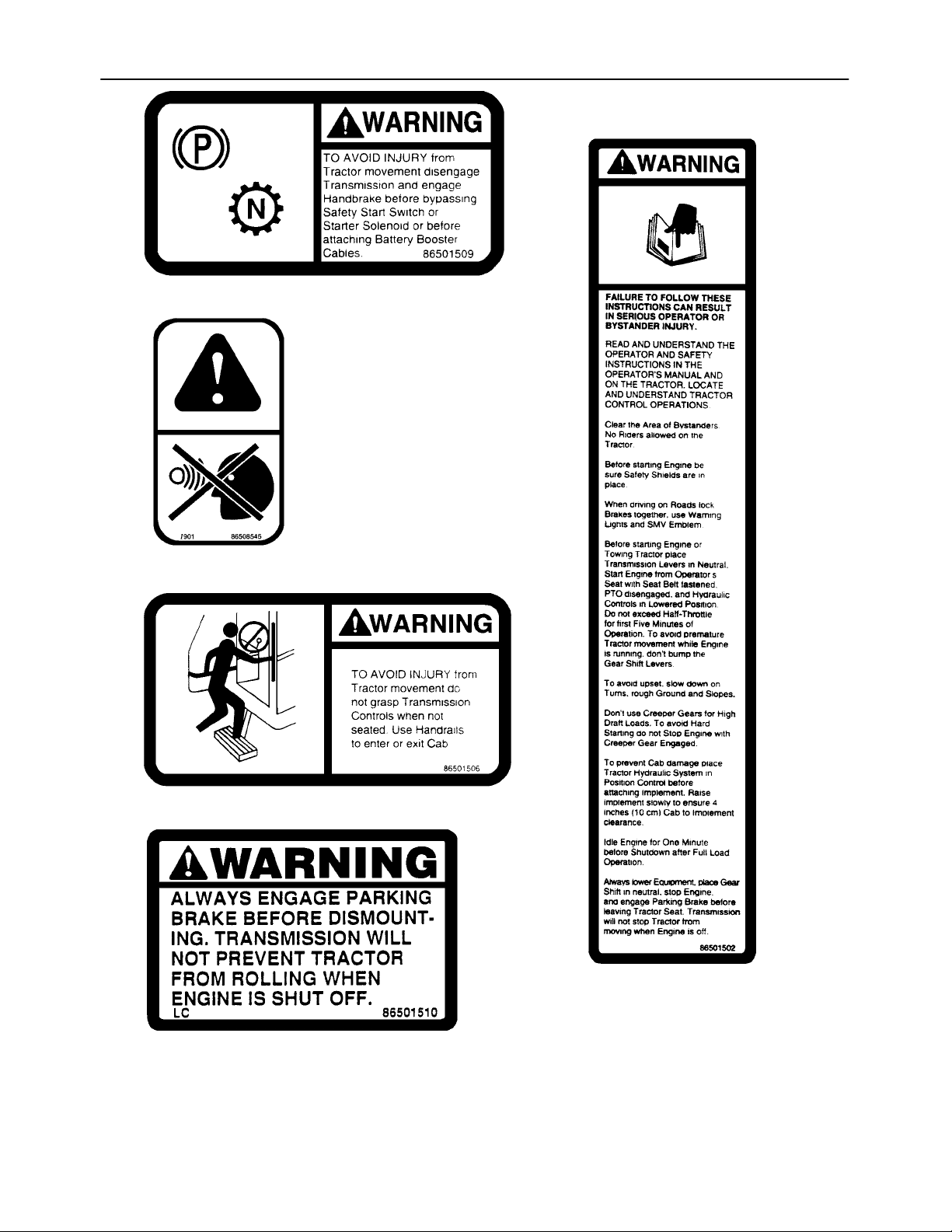
6. Location : Front of right side console
8. Location : Left-hand “B” pillar in the ca
7. Location : Top of right side console
0-12
SECTION 0 -- SAFETY
86516374
9. Location : Rear of both rear fenders
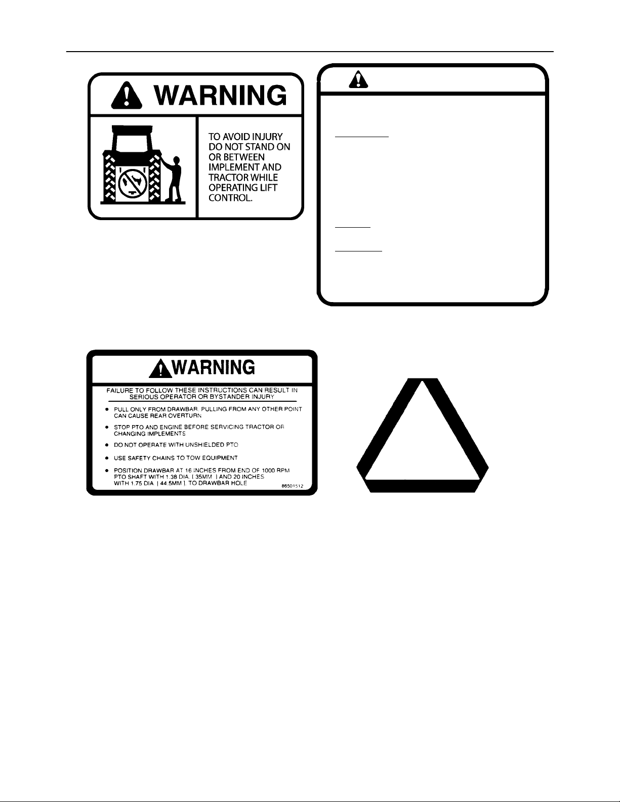
WARNING
IF INSTRUMENT PANEL FLASHES “STOP” AND
CONTINUOUS ALARM SOUNDS:
IMMEDIATEL
1. DEPRESS TOP OF SHUTDOWN OVERRIDE
SWITCH.
2. DOWNSHIFT TO 7TH GEAR OR LOWER.
3. PROCEED TO SAFE STOPPING AREA
AND STOP ENGINE.
4. DETERMINE CAUSE AND TAKE CORRECTIVE
ACTION.
DO NOT
ALARM SOUNDING.
IMPORT
FAILURE TO DEPRESS SWITCH WITHIN 30
SECONDS AFTER ALARM SOUNDS WILL STOP
ENGINE. CAUSING LOSS OF POWER-ASSIST TO
STEERING AND BRAKES.
11. Location : Lower front corner of right
Y
ATTEMPT TO DRIVE FURTHER W ITH
ANT
86002744
side window
10. Location : Below PTO stub shaft
12 – Slow-moving vehicle sign
Part #5144870
0-13
SECTION 0 -- SAFETY
SAFETY CAB/ROPS
Safety Cab/ROPS
A safety cab incorporating a Roll Over Protective
Structure (ROPS) and seat belt were standard
equipment for the tractor at time of factory assembly.
The seat belt, when used by the operator, maximizes
the protection offered by the ROPS.
WARNING
Always use your seat belt with the cab/ROPS.
Seat belts save lives when they are used.
Information regarding the safety cab/Roll Over
Protective Structure and seat belt are available from
your authorized dealer.
ROPS Maintenance and Inspection
After the first 50 hours of operation and every 300
hours of operation (or six months, whichever comes
first):
70-000-389
1
1. Check the torque of the cab/ROPS mounting
bolts. Refer to “Operation 41” in the “Lubrication
and Maintenance” section.
2. Check the operator’s seat mounting bolts and the
seat belt mounting bolts. Tighten bolts to 54 N·m
(40 ft lbs). Replace any worn or damaged parts.
Damage to the Cab/ROPS
If the tractor has rolled over or the cab/ROPS has
been damaged (such as striking an overhead object
during transport), it must be replaced to provide the
original protection.
After an accident, check for damage to the (1)
cab/ROPS, (2) operator’s seat, (3) seat belt and seat
belt mountings. Before you operate the tractor,
replace all damaged parts.
IMPORTANT: Do not try to weld or straighten the
cab/rops.
WARNING
Never attach chains, ropes or cables to the
cab/ROPS for pulling purposes; this will cause
the tractor to tip backwards. Always pull from the
tractor drawbar. Be careful when driving through
door openings or under low overhead objects.
Make sure there is sufficient overhead clearance
for the cab/ROPS.
If the cab/ROPS is removed or replaced, make
certain that the proper hardware is used and the
recommended torque values are applied to the
attaching bolts.
0-14

SECTION 0 -- SAFETY
UNIVERSAL SYMBOLS
As a guide to the operation of your tractor, various universal symbols have been utilized on the instruments, controls, switches, and fusebox. The symbols are shown below with an indication of their meaning.
0-15
EHR Power
40A

SECTION 0 -- SAFETY
0-16
SECTION 1 - GENERAL INFORMATION
INTRODUCTION TO THIS MANUAL
This manual has been prepared to assist you in the
correct procedure for running-in, driving, operating
and maintaining your tractor.
The manual is divided into five sections as detailed
in the “Contents” page. An index is provided at the
back of the manual.
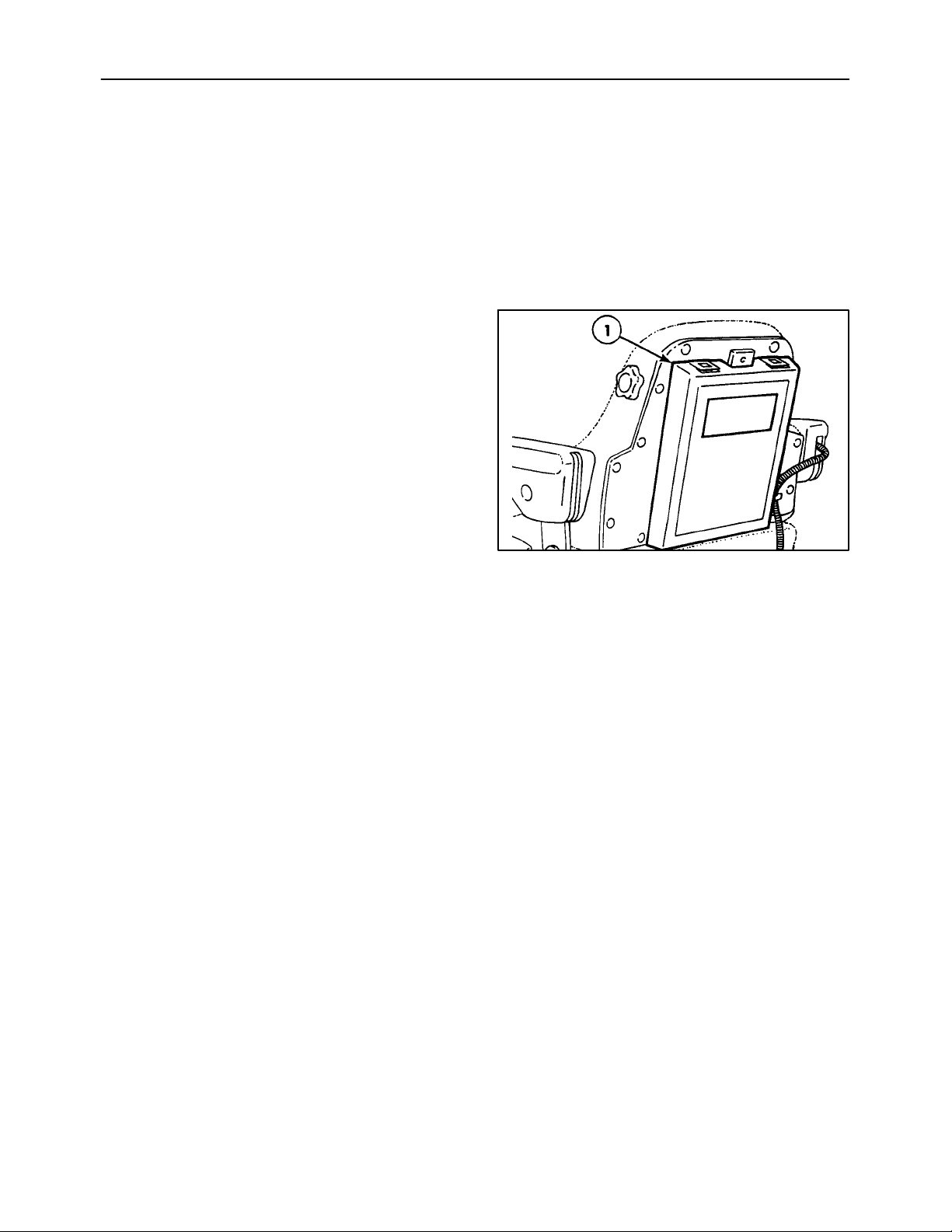
OPERATOR’S MANUAL HOLDER
A manual holder, 1, is attached to the rear of the seat.
Store the operator’s manual and other tractor
information in the holder.
Read this manual carefully and keep it in the manual
holder for future reference. If at any time you require
advice concerning your tractor, do not hesitate to
contact your authorized dealer. He has factorytrained personnel, genuine replacement parts, and
the necessary equipment to carry out your service
requirements.
Your tractor has been designed and built to give
maximum performance, economy and ease of
operation under a wide variety of operating
conditions. Prior to delivery, the tractor was carefully
inspected, both at the factory and by your dealer, to
ensure that it reaches you in optimum condition. To
maintain this condition and ensure trouble-free
operation, it is important that the routine services, as
specified in this manual, are carried out at the
recommended intervals.
All data given in this book is subject to production
variations. Dimensions and weights are approximate
only, and the illustrations do not necessarily show
tractors in standard condition. For exact information
1
about any particular tractor, please consult your
authorized dealer.
The company policy is one of continuous improvement, and the right to change prices, specifications
or equipment at any time without notice is reserved.
References to the right and left sides of the tractor are
determined by sitting in the operator’s seat facing the
direction of forward travel.
Pages 0-5 through 0-12 list the precautions to be
observed to ensure your safety and the safety of
others. Read the safety precautions carefully and
follow the advice offered BEFORE operating the
tractor.
1-1
SECTION 1 - GENERAL INFORMATION
TRACTOR IDENTIFICATION
TRACTOR IDENTIFICATION DATA
The tractor and major components are identified
using serial numbers and/or manufacturing codes.
The following provides the locations of the
identification data.
NOTE: Tractoridentification data must be supplied to
the dealer when requesting parts or service.
Identification data is needed to aid in identifying the
tractor if it is ever stolen.
Record the identification data in the sample ID plates
or on the lines provided.
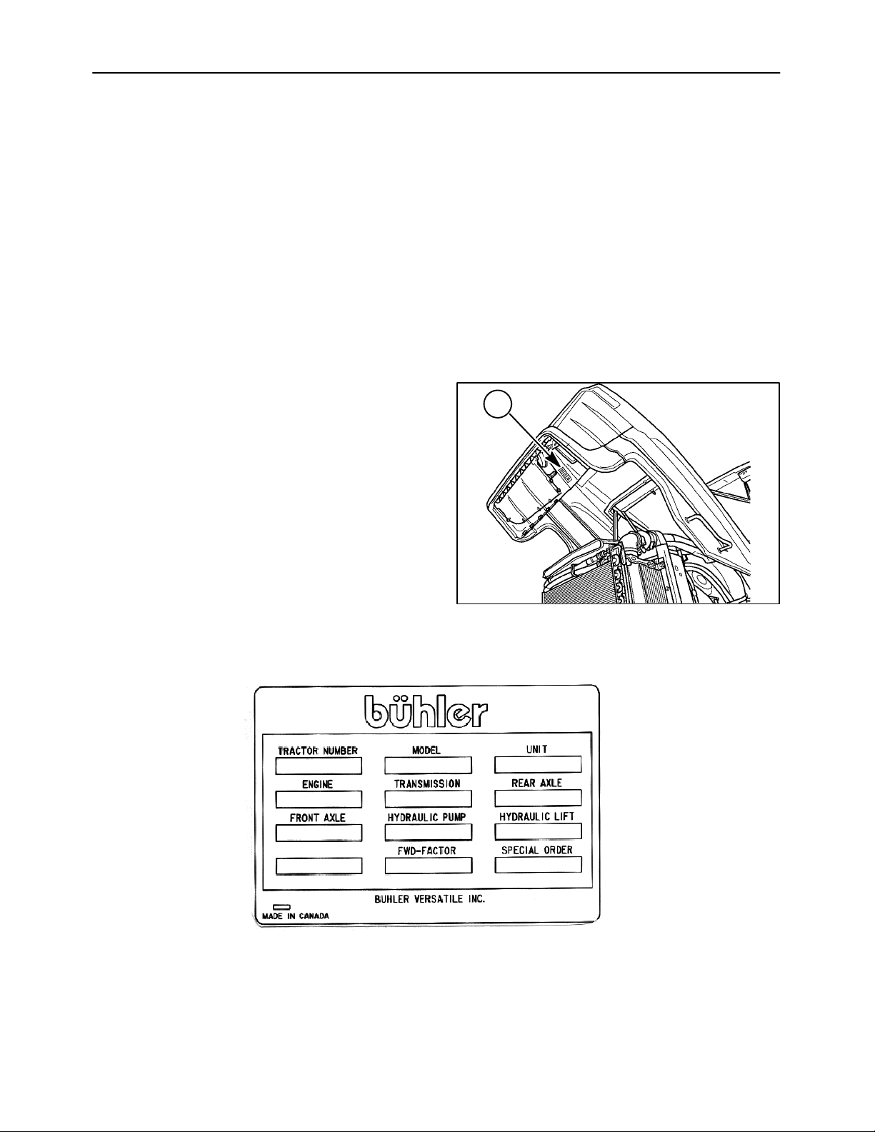
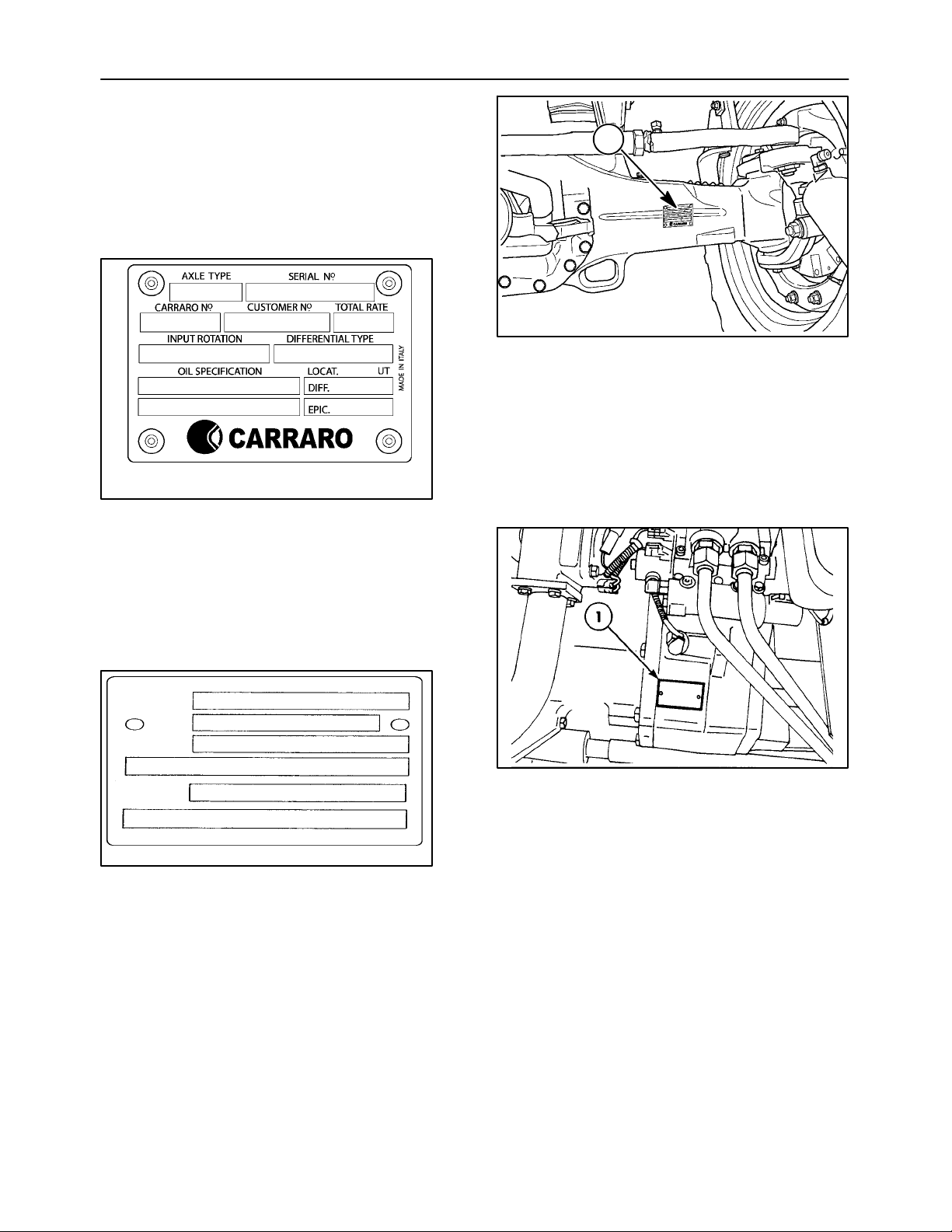
VEHICLE IDENTIFICATION PLATE
The vehicle identification plate, 1, is located inside
the right front lower side panel of the hood.
Record the information on the sample ID plate.
1
2
1-2
SECTION 1 - GENERAL INFORMATION
TRACTOR IDENTIFICATION
The serial number and identification information is
stamped on the top of the front support, 1. Record all
the numbers on the following line.
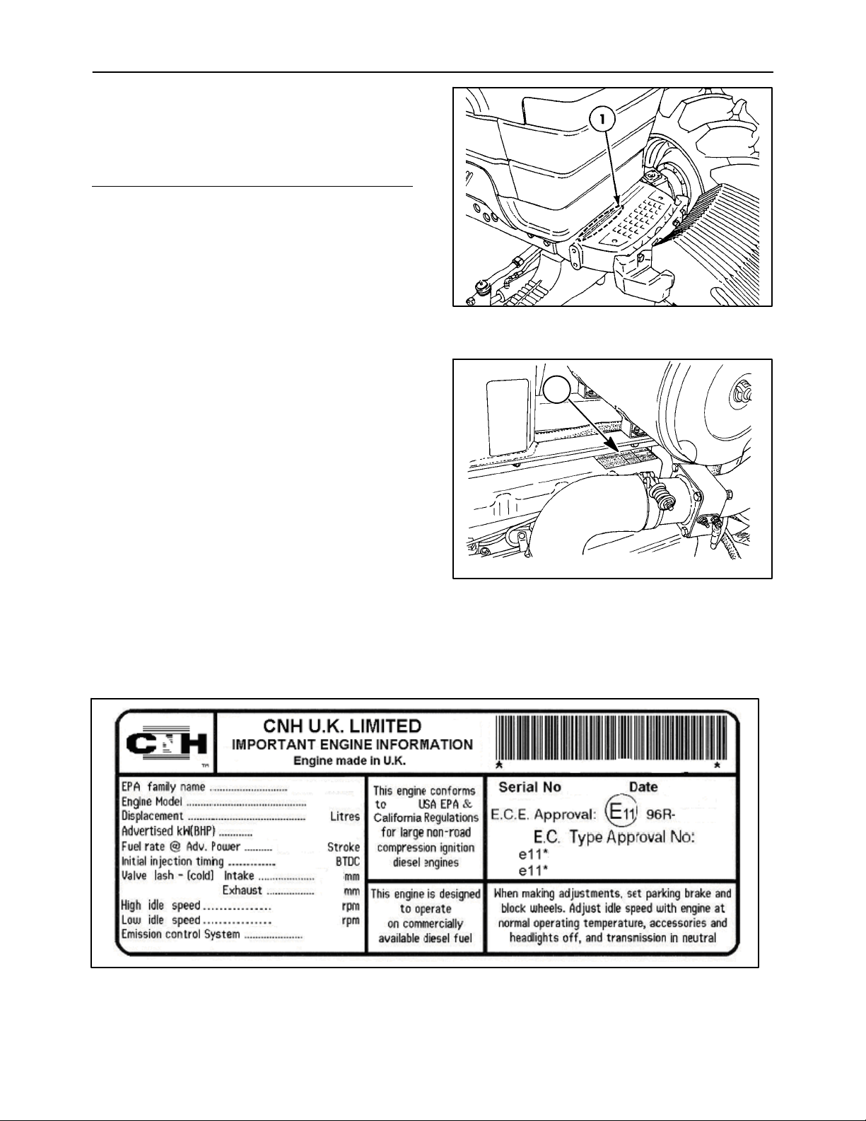
ENGINE IDENTIFICATION
The engine identification information is located on a
tag, 1, on the top front of the engine rocker cover.
Record the information on the sample ID plate. The
decal will appear similar to the illustration below.
3
1
4
1-3
SECTION 1 - GENERAL INFORMATION
FOUR WHEEL DRIVE (FWD) FRONT AXLE
IDENTIFICATION
The serial number and axle type are on the plate
located on the right rear of the axle housing, 1.
Record the information on the sample ID plate.
1
5
TRANSMISSION IDENTIFICATION
The serial number and type are located on the plate
on the lower right side of the transmission, 1.
Record the information on the sample ID plate.
MODEL
SPEC
SERIAL
EQUIP
6
1-4
SECTION 1 - GENERAL INFORMATION
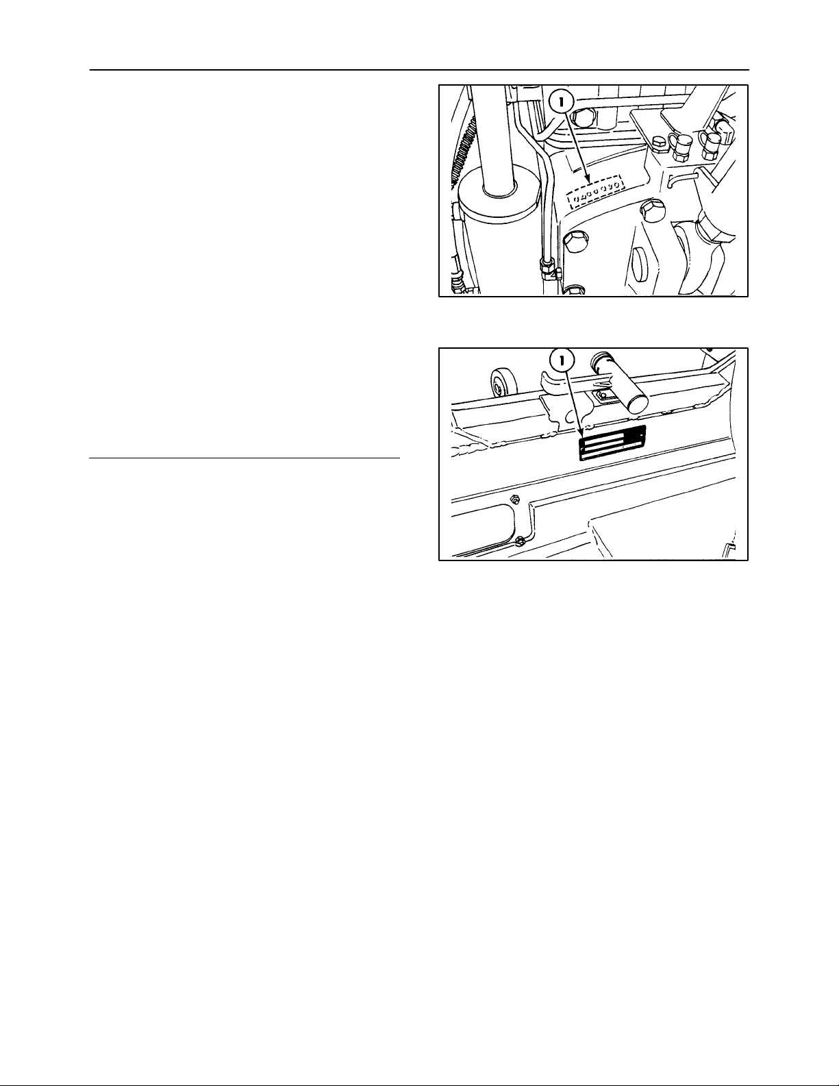
REAR AXLE IDENTIFICATION
The serial number is also stamped on the left side of
the PTO boss on the rear axle housing, 1.
CAB IDENTIFICATION
The serial number is on the certification plate on the
rear crossbar, 1.
Record the serial number on the following line.
7
8
1-5
SECTION 1 - GENERAL INFORMATION
PROTECTIVE SHIELDING
INTRODUCTION
Protective shields have been installed on your
tractor. The shields are intended for your safety and
for those working with you.
SHIELD LOCATIONS
Use the following as a guide and familiarize yourself
with the location of the protective shields.
WARNING
Install all protective shields before starting or
operating the tractor.
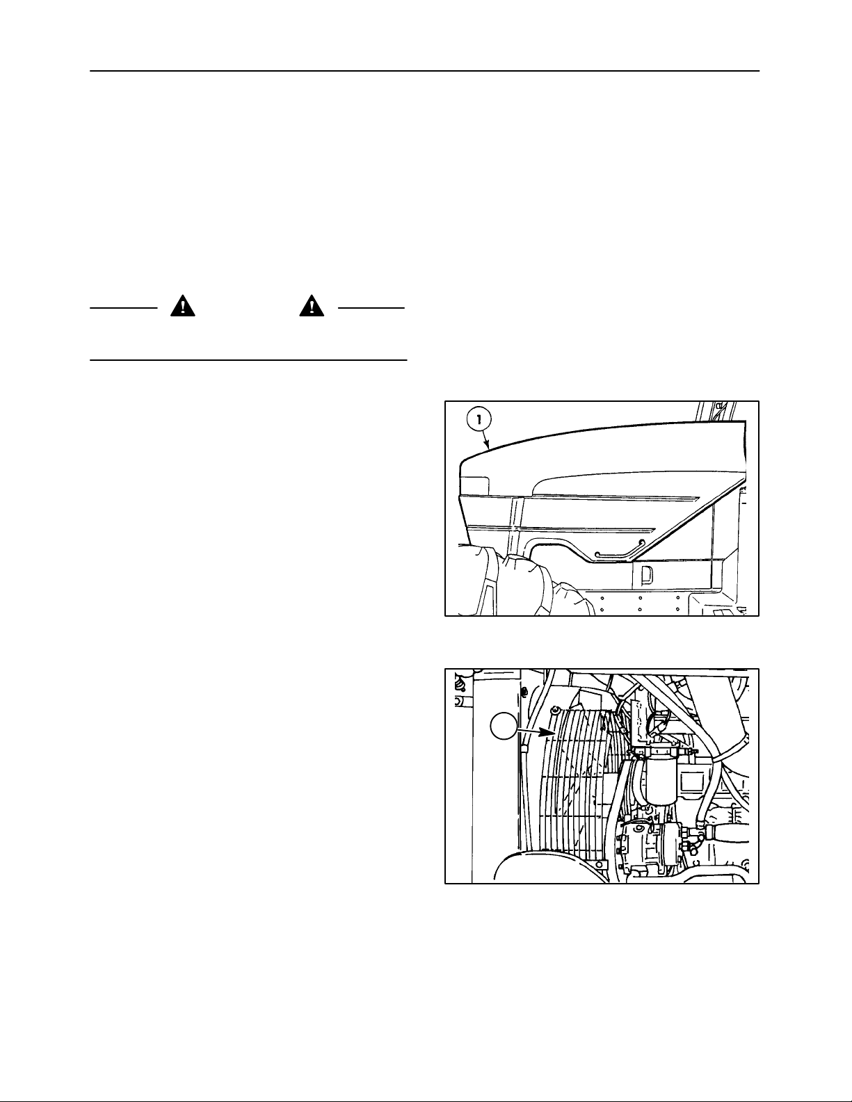
ENGINE HOOD
The hood, 1, covers the engine’s moving parts. The
hood must be closed before operating the tractor.
FAN SHIELDS - LEFT SIDE
The shield, 1, covers the left side of the fan.
9
1
10
1-6
SECTION 1 - GENERAL INFORMATION
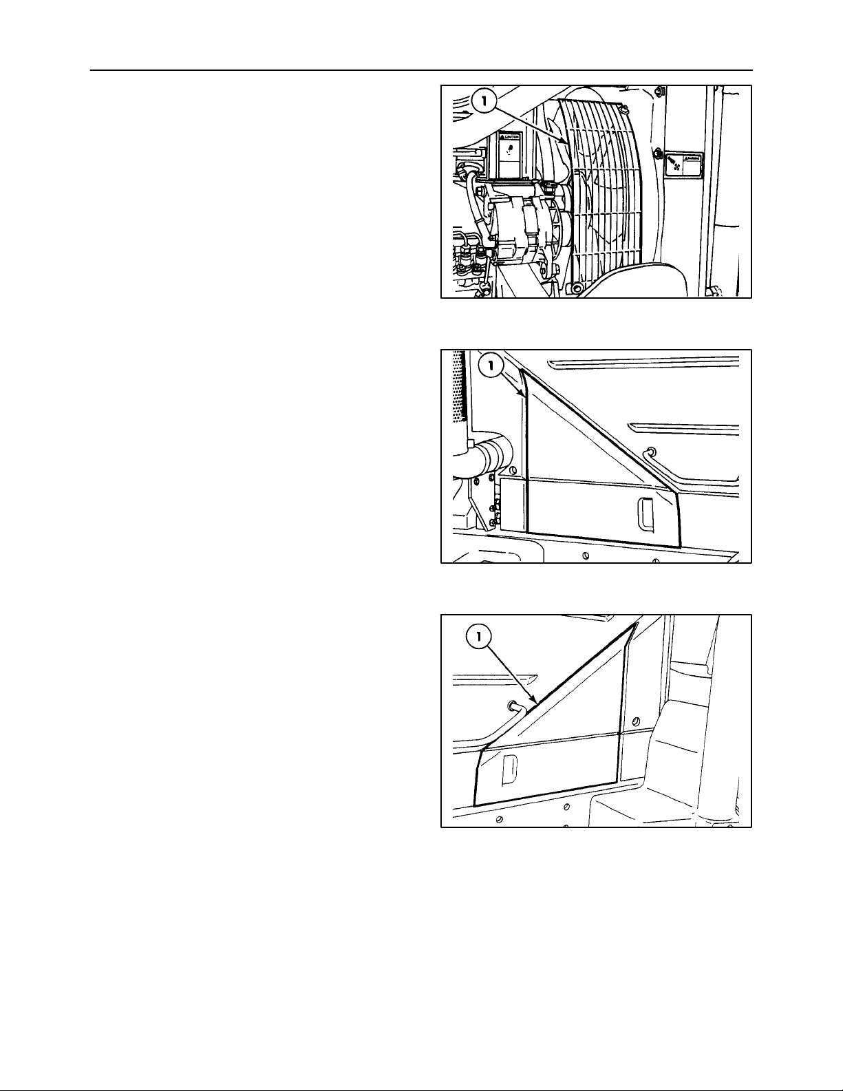
FAN SHIELDS - RIGHT SIDE
The shield, 1, covers the right side of the fan.
ENGINE ACCESS DOOR - RIGHT SIDE
The door, 1, covers the right rear engine
components.
11
ENGINE ACCESS DOOR - LEFT SIDE
The door, 1, covers the left rear engine components.
12
13
1-7
SECTION 1 - GENERAL INFORMATION
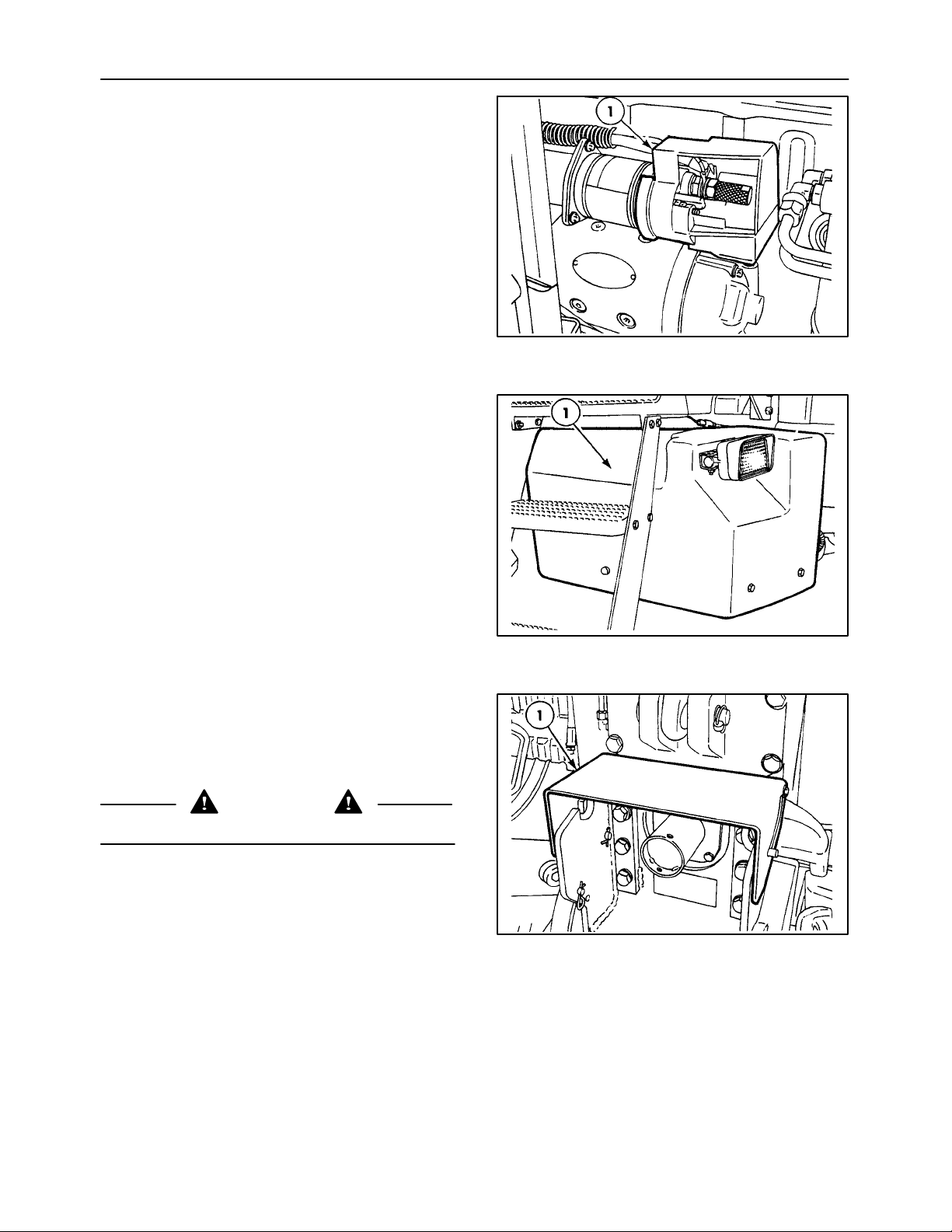
STARTER SOLENOID SHIELD
The shield, 1, covers the starter solenoid electrical
connections to prevent accidental contact. The
shield must be installed whenever the batteries are
connected to the electrical system.
BATTERY COVER
The cover, 1, protects the batteries from damage and
the electrical connections from accidental contact.
14
TRACTOR MASTER PTO SHIELD
The shield, 1, covers the tractor PTO stub shaft. The
shield can be pivoted to make installing a PTO shaft
easier.
CAUTION
Do not remove or modify the shield.
15
16
1-8
SECTION 1 - GENERAL INFORMATION
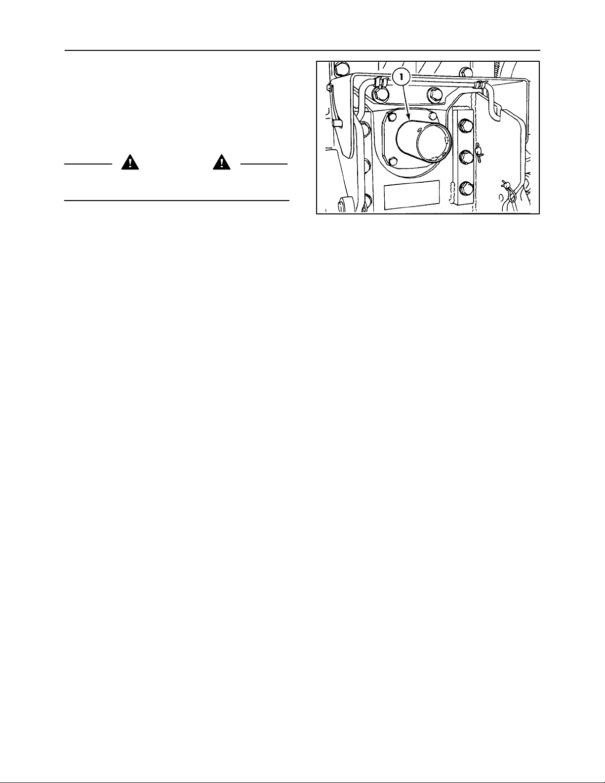
TRACTOR PTO STUB SHAFT COVER
Install the cover, 1, over the tractor’s PTO stub shaft
when the shaft is not attached to an implement. Turn
the shield counterclockwise to remove, and
clockwise to install.
Store the cover when removed.
WARNING
Install all protective shields before starting or
operating the tractor.
17
1-9

SECTION 1 - GENERAL INFORMATION
CONTROLS AND INSTRUMENTS - OVERVIEW OF LOCATION AND FUNCTION
The information on the following pages identifies,
locates and briefly describes the function of the
controls and instruments located in the cab.
The controls have been divided in to the following
four areas:
1. Forward operator controls
2. Foot and floor controls
3. Overhead controls
4. Right side console controls
IMPORTANT: The following information in this
section provides a general overview of location and
function but does not provide detailed operational
information. Thoroughly read Section 2 - “Operation”
for details on how to use the controls and read the
instruments before operating the tractor.
WARNING
Do not operate the tractor until you are
thoroughly accustomed with the location and
operation of all controls.
1-10
SECTION 1 - GENERAL INFORMATION
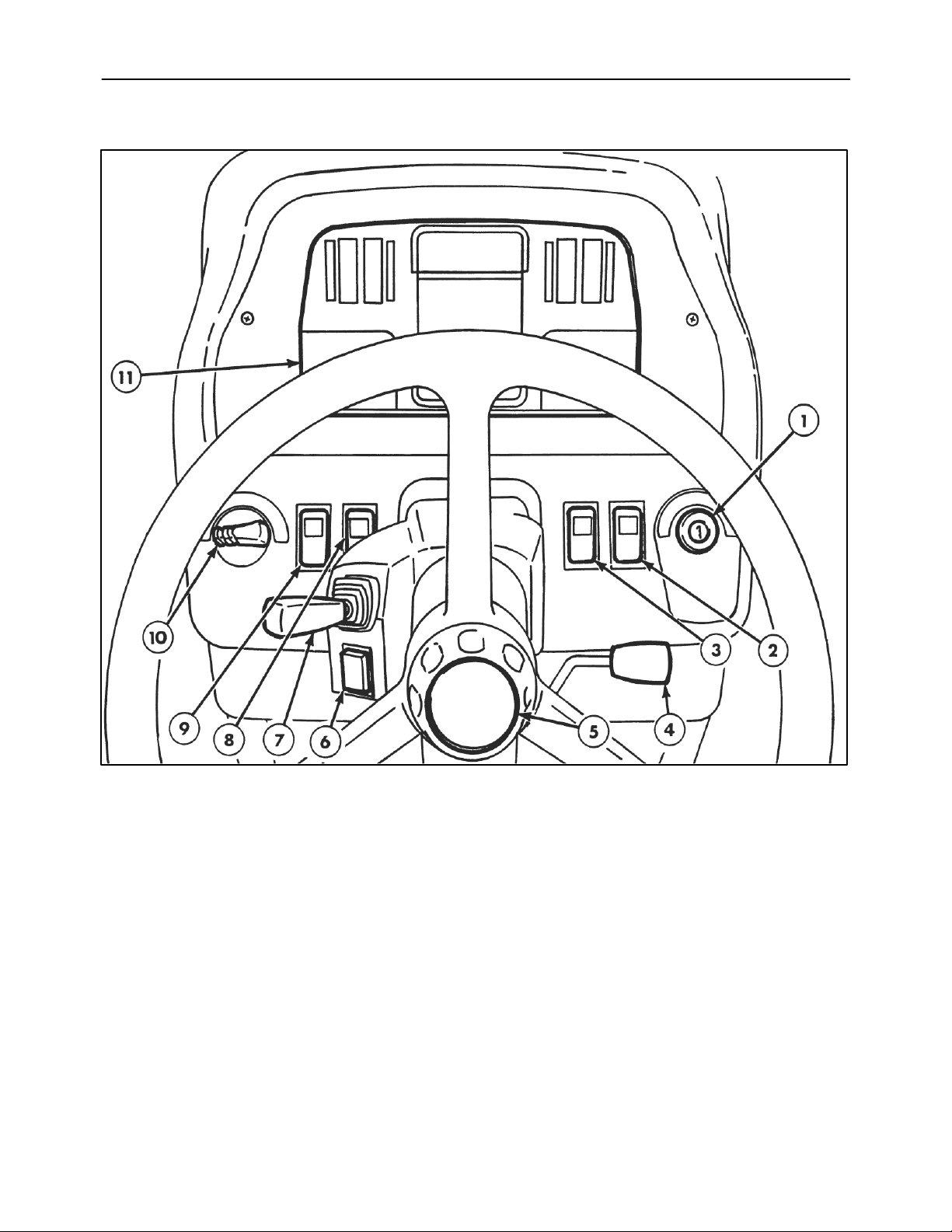
FORWARD OPERATOR CONTROLS
Forward Operator Controls
1. Key-start/stop switch, 4 position
2. Engine shutdown override switch
3. Creeper switch (if equipped)
4. Steering column tilt control lever
5. Steering column telescopic adjustment control knob
6. Cold start aid switch
7. Multi-function switch - horn, turn signal, high/low
beam
8. Rotary beacon switch (if equipped)
9. Hazard warning switch
10. Master light switch, 4 position
11. Electronic instrument cluster (EIC)
Each numbered item is discussed under the corresponding heading found on the following pages.
1-11
18
SECTION 1 - GENERAL INFORMATION
FORWARD OPERATOR CONTROLS
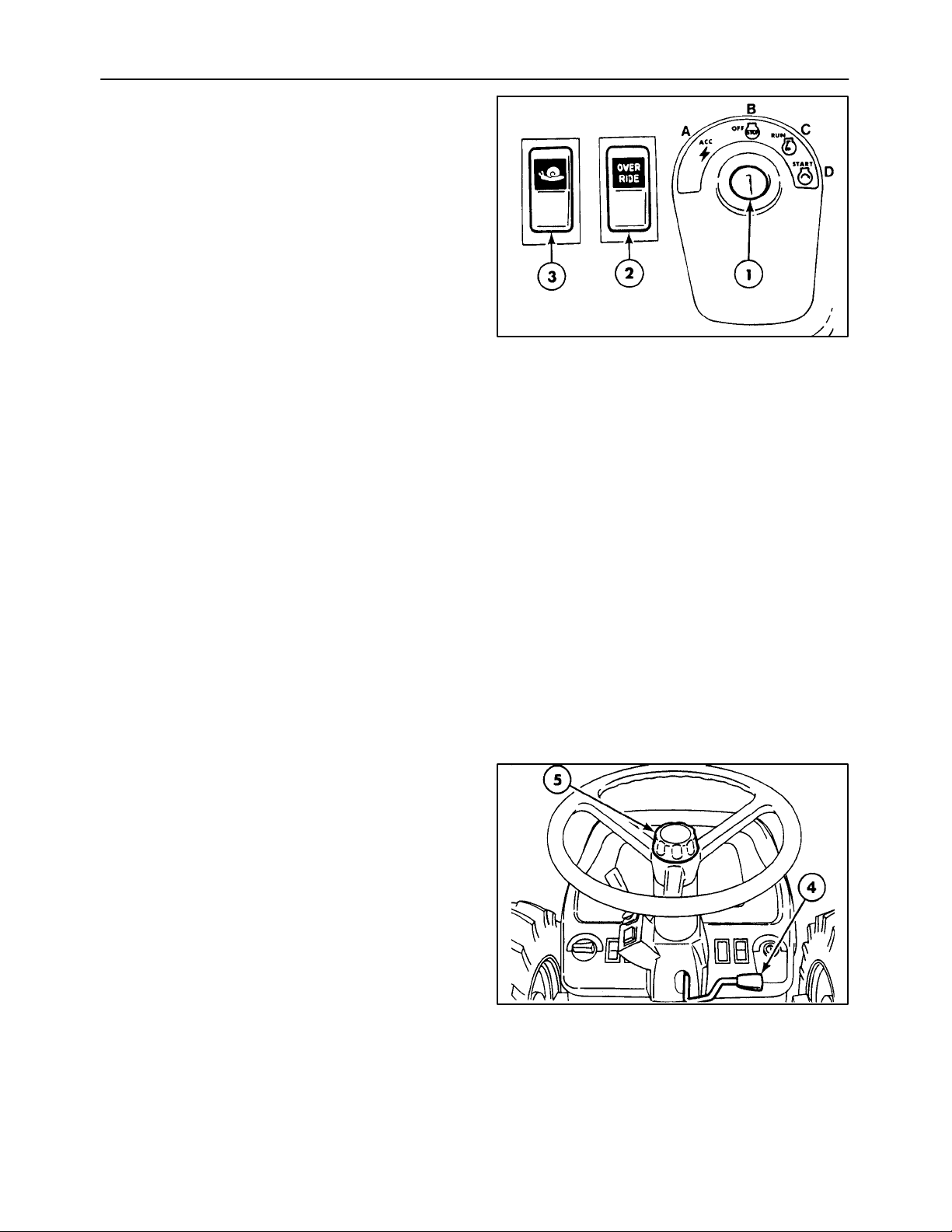
1. KEY-START/STOP SWITCH
The key start/stop rotary switch, 1, has four positions.
Position A - Accessories “ON,” Engine “OFF”
Position B - Engine and electrical equipment “OFF”
Position C - Warning lights and instruments “ON.”
Engine RUN position.
Position D - Starter motor operates
2. ENGINE SHUTDOWN OVERRIDE SWITCH
The two-position rocker switch, 2, allows the
operator to over ride the automatic shutdown. See
“Operating the Engine” for details on the automatic
shutdown feature. The switch s hould only be used to
move the tractor to a safe area for investigation and
repair. Push the top of the switch to override the
shutdown system. Push the bottom to return to
normal automatic shutdown operation.
3. CREEPER SWITCH (If Equipped)
The switch, 3, controls the engagement of the
creeper gears.
Push the top of the switch to select creeper. Push the
bottom of the switch to return to normal operation. Do
not select creeper unless the tractor has come to a
complete stop. See “Transmission Operation” for
details.
Tractors without creeper will have a blanking plate in
place of the switch.
4. STEERING COLUMN TILT CONTROL LEVER
Pulling on the lever, 4, allows the steering column to
be tilted up or down to a comfortable operating
position or out of the way for easy exit from the seat.
See “Cab” for details.
19
5. STEERING COLUMN TELESCOPIC ADJUSTMENT CONTROL KNOB
Rotating the knob, 5, allows the steering column to be
shortened or lengthened to a comfortable operating
position. See “Cab” for details.
20
1-12
 Loading...