

Page 1
SAVE THESE INSTRUCTIONS
ELECTRICAL GROUNDING INSTRUCTIONS
This appliance Is equipped with a three-wire (groundinB) plug for your
prutBclior against shock hazards and should be plugged directly Into a properly
grounded receptacla. Where a two-prong wall outlet Is encountered, K muet be
replaced with e properly grounded three prong outlst In eccordsnce with local
codes and ordinances. Do not under any drcunstancea cut or ramose the
grounding provision from this plug.
CONSERVE ESTAS INSTRUCCIONES
INSTRUCaONES 808RE LACONEXION ELECmCA A TIERRA
Este equipo está provisto de un enchufe trilásicc (con coneidán a tjerre) para
protegerlo a usted de peligros de sacudidas eláctncas y debe enchuterse
directamente a un tomacorriente conectado de forme adecuada a tierra. En los
cesoe en que se encuentre un tomecornente de pared de dos espgas, deberá
INSTRUCTION MANUAL For Operation & Service
MANUAL DE INSTRUCCIONES
Para Operación Y Servicio
Técnico
PLEASE READ AND FOLLOW ALL
INSTRUCTIONS
IMPORTANT SAFEGUARDS
When using your overhead projector, basic safety precautions should always be
followed. Including tha following:
Read and understand sll Instructions.
Close supervision Is rtscessary when any ap^lance Is used by or near
children. Do not lasw eppllance unsttenderd while In uae.
Care must be taken as burns can occur from touching hot perte.
Do not operate appliance with a damaged cord or H the eppllance has
been dropped or damaged - until It has been ewmlned by e qualified
Do not let cord hang over edge of table or counter or touch hot surfaces.
Arrange the cord so that It will not be tripped over or pulled.
If an extension cord Is neceseery, a cord with a sultaisle current rating
should be used. Suggest UL. raM ^ 0 amp (or more) line cord. Cords
rated for less amperage than the appliance may overheat.
Always unplug appliance from electrical outlet when not In uee. Never
yank cord to pull plug Irom outlet Grasp plug end pull to disconnect.
Let appliance cool completely before putting ewey. Store cord In power
cord storege compartment ot projector.
To protect against electricel shock hazards, do not Immerse this appliance
in water or other liquids.
To a«ld electric shock hazard do not disassemble this appliance, but
teke It to a qualified eervlceman when service or repair work Is required.
The uee ot an eccassory ettechment not recommended by the
manufacturer may causa a rtskot fire, electric shock, or Injury to per
Connect this appliance to a grounded outlet.
Disconnect this unit from Its source of suppy betöre repiedngthe
projection lamp.
«uae electric shock hazanf when the eppllance
SAVE ORIGINAL PACKING and ORIGINAL
CONSERVE EL ENVASE Y LA CAJA ORIGINALES
IMPORTANT
CARTON In ease of return.
IMPORTANTE
en eaeo de devolución.
POR FAVOR LEA Y CUMPLA TODAS
LAS INSTRUCCIONES MEDIDAS DE
SEGURIDAD IMPORTANTES
Al usar el retroproyeclor, se deben temar siempre precsuclonea básicas de
seguridad, induyendo les que aparecen a continuación:
Lea ycomprende todas las Instrucciones.
Es neceasrio establecer una estreche vigilancia cuando un nifto utiliza un
equipo o hey niñoe en loa alrededoree. No deje loe el equipo deaetendido
mientras esté en uso.
Se debe tener culdedo, ye que pueden producirse quemaduras el locar
pertes callentes.
No hage funcionar el equipo con un cordón eléctrico dañado o el el
mismo ee ha caído o danádo • hasta que haya sido Inspeccionado por un
técnico calificado.
No permita que el cordón quede colgando sobre el borde de la mesa o el
mostrador ni toque superficies callentes. Coloque el cordon de mártere
que nadie tropiace con el ni lo hále.
Si as r«cesario utilizar ur« extensión, deberá utTizarae un cable que
tenga la capacidad de corriente apropiada. Solicite un cordón con una
capacidad de 10 amperios (o más) que aparezca registrado en U.L. Los
cordones que tienen menos emperaje que el equipo pueden recalentarse.
Oeseoneele siempre el equipo del tomacorriente cuando no lo esté
usando. Nunca tire del cordón pare desenchufarlo. Tire del enchute pare
Oeje que el equipo ea enfrie completamente antea de guardarlo. Guarde
el cordón en el compartmiento destinedo a tal efecto que se halle en el
Pare protegerse de sacudidas eléctricas, no eumerja este equipo en agua
u otros líquidos.
Paraewler el riesgo de que se produzcan lesiones por sacudidas
eléctricas, no desarme este equipo, llévelo e un técnico calificado cuando
sea necesario repararlo o darle mantenimiento. SI e> equipo es armado
de forma Incorrecta pueden produdrae lesiones por sacudida eléctrica
cuando vuelva a utilizarse.
El uso de un accesorio que no haya sido recomendado por el fabricante
puede ocasionar un Incerdio, una sacudida eléctrica o lesiones a las
personas.
Conecta este equipo a un tomacorrienlea con cor«xión a tierra.
Desconecte este unidad del tomaconlenfa antes de sustituir la lámpara
de proyección.
Page 2

YOUR OVERHEAD PROJECTOR HAS BEEN
DESIGNED SO THAT YOUR OPEN HEAD AND POST
ASSEMBLY CAN BE STORED IN PROJECTOR WHEN
SHIPPED. OTHER HEAD STYLES ARE STORED IN
SHIPPING CARTON.
> Ramove the projector, and any acceeeones Ircm the shipping container.
• Sa^iQ tha ahipping carton together with foam Insarts, should the unit require
reahipping at s later deta.
MOUNTING THE HEAD AND POST ASSEMBLIES TO
Dapreea cover latch laDs on Doth sidaa of cover and lift oft cover.
Rotate 2 labs and lift post out of unit. Remove fixing screw from post. Raset
labs to lacigng position to provide proper seating of cover.
Ilnsert post Into mounting slof and engage holes with alignment pins or unit.
Secure post with fixing screw.
Using Philips screwdriver, remote brecitet that secures the open heed
assembly.
Position head as shown In diagram and slide or? post, turning focusing knob at
the same lime.
Mount optional roller attachments on front and back of unit. Remove front and
raar plastic plug buttons to expose mounting holes. Secure roller attachments
to front and rear using thumb screws provided wrth roller attachment.
1. Place the projactor on a firm, le<,«l aurtace at e convenient opareting height.
(Do not cover tha vents at both aides of projector.)
Z. Ilnaert power cord into a grounded electrical outlet and actuate power switch.
3. Place e transparency on the stage and turn locus knob alowly urrtil image is in
locus. Screen Image elevation ia changed by moving the top porton of the
head mirror upward or downward as required.
(See additional notes on focusing in Troubleehooting Hints).
INSTRUCTIONS FOR OPTIONAL LAMP CHANGER
lit you have purchased lamp changer model, please nota the following:
t. A lever located in the front of the unkactuefes the switching of one projection
lamp to another. Make sure tha lev«r is latched into end slots of travel path, or
unll will not function properly.
NQTEtTum power switch OFF prior to lamp changing.
2. The urrit comes standard with one projection lamp. An additional lamp must be
installed for lamp changing cepablllty.
The unit will automatically shut off when It reachea maximum temperature. If fan
outlet IS obstructed, or Ian la not working properly, this will happen. The thennal
switch will reset automatically when Ihe unit has cooled down,
THE PROJECTOR
SIMPLE TO OPERATE
AUTOMATIC THERMAL SWITCH
OPENING PROJECTOR
m wall socket. Then, gently depress both
CLOSING PROJECTOR
COOLING THE PROJECTOR
REPLACEMENT OF PROJECTION LAMP
2. For projectors with light boosters, depress spring latch secunng the light
booster assembly and lift the eqiosed projection lamp. Remove defective
lamp. Replace lamp by holding lamp with either a cloth or plaat'ic envelopa (do
not touch lamp with bare hends). Insart lamp pins Into lamp socket. Secure
lamp booster aasemUy and close projector.
EL RETROPROYECTOR НА SIDO DISEÑADO DE
MANERA QUE SE PUEDAN GUARDAR LA CABEZA
ABIERTA Y EL CONJUNTO DEL POSTE EN EL PROYE
CTOR CUANDO SE EMBARCA. LOS DEMAS TIPOS DE
CABEZAS SE GUARDAN EN LA CAJA DE EMBARQUE.
• Saque el proyector, y loa accasoríos del contenedor de embanque.
> Guarde le cajajurto con los protectores de espuma, an caeo de que necesitB
volver a emba/oar la unidad an techa pcaterlor.
COMO MONTAR LOS CONJUNTOS DE LA
CABEZA Y EL POSTE EN EL PROYECTOR
1. Baje las lengüetas de retención aituadas a ambos lados de la tapa y levente Ja
2. Неде girar las 2 lengüetas y saque al poete da la unidad. Quite el lomillo de
fijación del poete. Vuelve a colocar las lengüetas en la posición de retención
pera que la tapa aaiente bien.
3. Inserte el poste en le ranura de montaje y alinee loa agujerea con los
pasadores de la unidad. Fije el poste con el tomillo de fijación.
4. Usando un destornillador Philips, saque la plaza de sujeción que lija el
conjunto de ia cabeza ablerte.
5. Coloque la cabeza como ae muestra en el diagrema y deslicele por el poste,
al mismo tiempo que hace girar la parllla de enfoque.
3. Monte los accesodoe de rodillos en el frente y le parta poaterlor de la unlded.
Quite los botones de plástico de la parte delantera y posterior pare que
puedan verse los egujeroa de monteje. Rje los accesorios de rodillos en al
trente y la parta poaterlor usando los tcmillos de mariposa provistos con el
accesorio de rodillo
1. Coloque el proyector en una euperficie firme y nivelada, a unaalture de
Operación adecuada. (He cubra ios respiraderos situados a ambos lados del
proyector).
2. Inserte el cordon eléctrico en un tómacorrlente con conexión e Sena y
enciende el Interruptor.
3. Coloque una tranaparancie en el portal^inas y haga girar la perilla de
ertfoque lentamente hastá que la Imagen quede enloceda. La elevación de la
imagen en le pantalle ea cambia moviendo la porción superior del eepejo de la
cabeza hacia arribe o abejo, según sea neceearto.
(Vea las ncitaa adicionales sobre el tema enfoque en la sección Sugerencias
’ sobre le Looallzeaon de Fallas.)
INSTRUCCIONES PARA UTILIZAR EL CAMBIADOR DE
SI ha comprado el modelo de cambiador de lepara, tenga en cuente lo siguiente:
1. Une palanca sltuede al frente de la unldOd acciona el cambio de una lámpere
de proyección e la otra. Aaegúreeada que la palanca está trabada en lea
ranuras de los extremos dOl recorrido, o la unidad no funcionara bien.
NOTA: Deeconacle el rótemjptor eléctrico ("OFF') entes dé cambiar la lámpara.
2. La urtided viene estander con una lampara de pró^cclon. Se deberá colocar
una lampara adicional para poder tañer la capacidad de Intercambiar
La unidad sé epagera automátloameiite cuendo alcance lá temparetura maxima.
Eao ocurrirá ai ee obstruye la salida del ventilador o el venliledor no esta trabejandr
Oían. El Interruptor tennlco restablecerá automaticamente la conetóon cuendo le
unidad se haya enfriado.
FACIL DE OPERAR
LAMPARAS OPCIONAL
INTERRUPTOR TERMICO AUTOMATICO
COMO ABRIR EL PROYECTOR
COMO CERRAR EL PROYECTOR
COMO ENFRIAR EL PROYECTOR
Desenchufe el cordon eléctrico y abra le tape superior. El calor se disipare en unos
minutoB. No muevte la unidad hasta que se refresque. Una vez que esta fresca,
puede moverla, guardería, etc.
COMO CAMBIAR LA LAMPARA DE PROYECaON
1. Deeconecte el cordón del tomacorriente de la pared. Deje enfriar si proyector
antes de ebrirlo. Luego, abra el conjunto de la cubierta superior dál proyector
oprimiendo los retenedores situados a ambos lados de esta.
2. En el caeo de los proyectores que tienen ampllficadoree de luz. baje el
relanedor de resorte que fija e) amplificador de luz y levante lá lampara de
proyecólon. Seque lá lampara defectuosa y reém^acela sujetándole con On
parvo o con une fúnda plastice (no toque la lampare ein protegerse les manos).
Inserte los passdoras de lá lampara en la tome de la lampara. Fije el conjunto
amplificador de lampara y cierre el proyector.
Page 3

FRESNEL:
t 1. Press latches at both sides of cover, lift off c(
two tabs securing freansl lens and remove le
2. Carefully clean tresnel lena with a damp, soft cloth. Alcohol or other solwnts
MUST NOT be used. The bottom surfece of stage glass also should be
cleened In ihe same manner at this time.
3. Return tresnel lens into frame using the reveres procedure noted In step 1.
4. Fresnel ■ 'UP' marted In comer - Is the side teeing up toward projection heed.
Stage Glass:
Clean with e damp, soft clem.
EASY TO CLEAN FACIL DE LIMPIAR
id turn upeide down. Rotate
TROUBLESHOOTING HINTS
Unit will not turn on
1. Check if power cord is plugged into opereiing outlei.
2. Check If power switch is In "ON* position.
3. Check II top lid of unit is securely closed. Unit will not operate If lid is
open, as Ihe Interlock switch will not be In an activated position.
4. Thermal switch could shut the unH down If it Is running loo hot. Walt tor
the unit to cool down autlicientlyforthe automatic thermal switehto reset
5. If only blower Is operating, check to see If the lamp Is property seated and
nof defective or blown out
Unit will not focus
Check that the tresnel lens Is properly seated and centered In the cover
cavity. To do this, reirov« top cover by preesing both letch tabs on each
side of the projector almUteneoualy end lift cov«rfrom bottom housing.
Rotate the two plastic lens locks that hold the Iresnel In place, reeest the
frasnel lens In its proper position end rotate lens lock Into holding position.
Fresnel lens should be held securely In pdece.
For uneven light distribution
All projector heads are factory adjusted but can be adjusted in the field.
This can be acoompllehed by loosening two screws behind the heed for
lateral adjustment or four screws adjacent to the focus knob for horlzentel
adjustment. Correct alignment will result when the light cone passes
through the center of the heed lens. Secure ell screws.
Difficulty in moving pro|ection
head up and down the focus column
Increase or decrease tension on the focusing krvob by rotating the tension
screw In the bottom center of the post bracket In either a clockwise or
countetelockwise direction. Adjust so that the heed can be easily moved
up and down on the locueing column by rotating the tocue knob.
FRESNEL-
1. Oprima I a ambos lados de la tapa, levántele у vírela
le absjo. Mega girar las dos lengüetas que fijan los le
2. Limpie con cridado los lentes Fresnel cor un paño húmedo suave. NO ee
debe usar alcohol ni otros solventes. La superficie del tondo del vidrio del
poriaminas también debe limpiarse de la misma torma en ese momento,
3. Vuelva a colocar los lentes Fresnel en el merco, realizando a te Inversa el
4. B ledo del lente que dice - 'UP* (HACIA ARRIBA) en una aaquina ea el qua
debe colocarse mirando hacia le cabeza de proyección.
Vidrio del Portalemlnas:
Limpíele cen un peñe húmedo y suave.
in limpiedor de lentes, alcohol o ui
RECOMENDACIONES SOBRE LOCALIZACION
La unidad no ae enciende
1. Cornpru^ si el cordón de corrienta está conectado a un tomacorriente
que funcione.
2. Compruebe que el intermptor está en la i^lelbn 'ON' (Encendido).
3. Compruebe que la tapa superior de le unidad está bien cerrada. La
unidad no funcionará si la tapa está aUerta, debidos que el Intermptor de
endavamiento no estará en la posición activada.
4. El Intermptor térmico podrfa apagar la unidad si ésta comienza a
recalentarse. Espere a que la unidad ee enfrie lo suficiente para que el
Interruptor térmico automático restablezca la conenón.
5. SI solamente está funcionendo el ventilador, eeegúrese de que le
lámpere está bien colocada, no tenga defactos ni está tundda.
NOTA: La unidad se apagará eutomátlcamente cuando alcance la temperatura
márdma. Si el orificio de salida del de aire del ventlledor este obetmiqo, o
el ventlledor no esté tuncáonando den, le unidad ae apegará.
La unidad no enfoca
Compruebe que los lentes Fresnel esten bien colocados y an el centro de
la cevfded de le cubierta. Pera ello, quUe la cubierta superior haciendo
presión al mismo tiempo sobre embaa langústas da retención situadas a
cada ledo del proyector, separándole de le ceja Inteiior. Haga rotar las
doa trabas plásilcas que mantlerven los lurtes en su lugar, ponga toe
lentes en la posición edecuade y vuelve e rotar las Irabás hacia el punto
de fijación. Loa lentes Fresnel daben mantenerse fijos en su tugar.
En caso de que la luz se distribuya de forma no uniforme
Todas las cabezas del proyector vienen ajustadas de le tábrice, pero
pueden ajustarse en el campo. Esto puede hacerse aflojando dos tomillos
situados deffas de la cabeza para hacer el ajuste lateral, o cuatro lomillos
edyecentes a le perilla de enteque pare hecer el ajuste horlzcmal. Loa
lerttea quedaran bien alineados cuando el cono de luz pase por el centro
de loe lentes de la cabeza. Apriete bien todos loe tomlllós.
Resuita difícil mover la cabeza del proyector hada arriba y
hacia abajo por la columna de enfoque
Aumente o disminúye le tenélon de le perilla de enfoque haciendo girár el
tomillo da tensión que esta abajo y en el centro de le pieza de eujaclon si
posta hacia la derecha ó hacia le Izquierda, gústela de manera que le
cabeza puede moveree fácilmente hacia arribe o hacia abajo a lo largo de
la columna de enloque al hacer girar le perilla.
DE FALLAS
Page 4
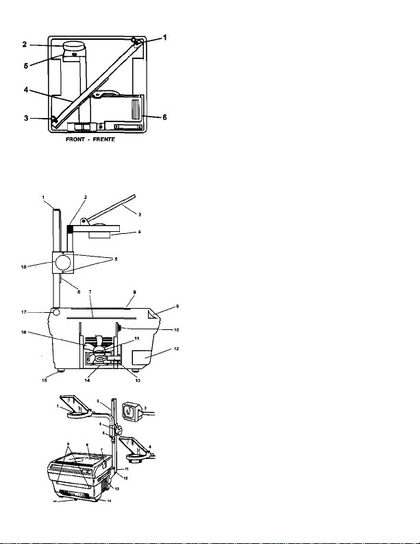
AREA PARA GUARDAR LA CABEZA/EL POSTE
NOTE: When not in use, Stow power cord in compartment at front of unit.
NOTA: Cuando nose esté usando el equipo, guarde el cwdén électricoen el compartimiento del Frente de la unidad.
HEAD/POST STORAGE
POST
HEAD
MIRROR
REPLACEMENT PARTS DIAGRAM
DIAGRAMA DE PIEZAS DE REPUESTO
1. POST
2. LATERAL ADJ. SCREWS (2)
3. MIRROR
4. OBJECTIVE LENS
5. HORIZONTAL ADJUSTMENT
SCREWS (4) CTWO ON EACH SIDE)
e. RACK
7. FRESNEL LENS
S. OBJECT (STAGE) GLASS
9. POWER SWITCH
10. THERMAL SWITCH
11. LIGHT BOOSTER
12. POWER CORD STORAGE
13. LAMP SOCKET
14. REFLECTOR
15. FOOT
15. FAN ASSY. AND MOTOR
17. FIXING SCREW
ie. FOCUSING KNOB WITH PINION
GEAR
1B. LAMP CHANGER LEVER
1. LENGÜETA
2. PERILLA
3. LENGÜETA
4. POSTE
5. CABEZA
6. ESPEJO
1. POSTE
2. TORNILLOS DE AJUSTE LATERAL (2)
3. ESPEJO
4. LENTE DEL OBJETIVO
5. TORNILLOS DE AJUSTE HORIZIONTAL
(4) (DOS A CADA LADO)
6. CREMALLERA
7. LENTE DEL FRESNEL
e. OBJETIVO (PORTALAMINAS)
e. INTERRUPTORES DE CORRIENTE
10. INTERRUPTOR TERMICO
11. AMPLIFICADOR DE LUZ
12. COMPARTIMIEFiTO PARA GUARDAR
ELCORDON
13. TOMA DE LA LAMPARA
14. REFLECTOR
15. BASE
ie. CONJUNTO DE VENTILADOR Y
MOTOR
17. TORNILLO DE FIJACION
ie. PERILLA DE ENFOQUE CON PINON
DIFERENCIAL
IB. PALANCA DEL CAMBIADOR DE
LAMPARAS
1. OPEN HEAD
2. POST
aCLOSEDHEAO
4. TRIPLE LENS HEAD
5. FOCUSNQ KNOB
e. FOCUS KNOB TENSION SCREW
7. COVER LATCH TAB
e. STAGE
9. RCXiER ATTACHMENT HOLES
10. LAMP CHANGER LEVER
11. POST MOUNTING FIXING
SCREW (»SIDE)
12 POST MOUNTING SLOT
ia POFTTABILFTY HANDLE
14. POWER CORD STORAGE
ID 041 142 400 RevA
I. CABEZA ABIERTA
2 POSTE
3. CABEZA CERRADA
4. CABEZA DE TRES LBTTES TRIPLES
S PERILLA DE ENFOQUE
a TORNILLO DE TENSION DE LA PERILLA
DE ENFOQUE
7. LENGÜETA DE RETENCION DE LA
CUBIERTA
a PORT ALAMINAS
B. AGUJEROS DEL ACCESORIO DE
RODILLO
10. PALANCADELCAMBWDORDE
LAMPARAS
II. TORNILLO DE FUACDN DE MONTAJE
DEL POSTE (INTERIOR)
12 RANURA DE MONTAJE DEL POSTE
13. AGARRADERA
14. COMPARTIMIENTO PARA GUARDAR EL
CORDON DE CORRIENTE
Page 5
REPLACEMENT OF PROJECTION LAMP
Tor pra^ion «rith light booetets, depiaM «prlng latch «aouhnc th« light
booMr ■ssefflbly and INI the apowd prci)ecBor lamp. Remove detective
lamp. ReMuB lerr*) ^ hoUng lamp with eKhar a cloth or ptaatlc envatopa (cli
not touch tamp wMi bare bande). Inaerl lamp pha into lamp socket. Secure
lamp boowar aseembly and oMea pro)actor.
EASY TO CLEAN
FftESNEL:
1. Prassietcbeeatbotheidesoleover, im off cover and turn upaMe down. Rotate
two tabs aacurfng fteanat Ian* and remove lens.
г Carefully cleen fiaenel lenewNh e demp. eoft doth. Alcohol or other aolvenis
MUST NOT be ueed. Tlie bottom eurfaM ol stage glass aiao tnouM be
cleaned Irt me same manner at this Ikne.
3. Return Iraanal lene Irvo frame usirtg the reverse procedure noted ki step 1.
4. Presnal • IIP'marked In comer-lathe aide lacing up Icmardprotecdar heed.
Staff« a/Ms:
Clear wtih a dajnp, аоП doth.
Clean lena and mirror with lens cleaner, elcohol or damp r.lolh.
SCHEMATIC DIAGRAM
■“В—1
THíiBiK(.7
и ^
LAMP CHANGER VERSION ' BASIC VERSION
~В—1
■А.р\
П BOD*
^рвотестс*
INSTRUCTIONS FOR OPTIONAL LAMP CHANGER
ill you nave purchased lamp changer modd, ptoase no» the bllowingr
t. AleverhKaIedlnthafion(ofirMurTffecluate*cneew№Nrtgofonepra|eedori
larpp lo another. Make aute Ihe lever le lalchaa Into and aim ol Irevel path, or
unit will not function properly.
NOTE:Tum power awlteh OFF prior lo lamp changing.
2. The unll cornea etandard with one protection tatnp. An eddUcmilamp must be
installed lor lamp changino capabnity-
1. Ptace me projeetor on a firm, level surface at a convenient operating height
2. iinsert power cord into a grounded etactricai outlet and actuate power switch.
3. Fiaee a irenaparency on the stage and turn focus knob slowly until Image is In
The unit wiN auiotnaOtwily shut on when It reaches maximum tenverature. It (an
ouUel le cbstnxted. or (an Is riot working ргореЛу. will happen. The thenrtal
ewftch will reset autometlcalty when the unit has cooled down.
Alwaya first dlsconneet power cord from wall socket. Then, gently doprese boih
cmrer laiehee and lift cover.
Lower 4d, puanlng do«m until aide latches are locked. At this point, trw unit is eloeed
Unpkjg power cord. Open lop lid. The heal will disslpaie wiiMn a few minutes bo
irol move the ипП until cool. Ones cool, you cart move, store, etc.
SIMPLE TO OPERATE
(Do not cover the vents at both sides of pmtactor.)
locue. Screert Imege elevation Is changed by moving the icp portion ol the
heed mirror upward or downward as teculrad.
(See eddHlor«l пома on locuelfig In TrcubleehooUng Hktis),
AUTOMATIC THERMAL SWITCH
OPENING PROJECTOR
CLOSING PROJECTOR
COOUNQ THE PROJECTOR
COMO CAMBIAR LA LAMPARA DE PROYECCION
1. Dosconecte ft corddn del tomacomente de la pared. enfhar el proyector
antes de abrirlo. Luego, tóre at eor||unlo de Is cubierta superior del proyector
oprimiendo loe retaneoores sttuadoe a ambo« lados de esta,
i. En si casode ioeproyectoree quettanen ampiMcadoresde Iu2. be)esi
retenedor de reso^ que (Ha ai ampUflcador de Im y levente lá lampara de
proyección. Saque lá lampara datactuosa y reámptacsla aujatandota con On
paño o oon una (ünda pfaaHce (no ioqua la lampara sin protegerá» la» manca).
Inaerle ioa pasadores da tá larnpara en la torna de la lampara. Fi)e el conjunto
ampltncador de lampara y cierre el proyector
FACIL DE LIMPIAR
4. El'ltód«wíÍIlB^Í*M-^UP"°^
debe cttioearse mirando hacia le cabéis de proyección.
Vidrio dtl Porlalamina»:
Llmpielo con un paho húmodo y auave.
Urrple los tontea y el espefo con un limpiader de lenlea, atc^i o un peho húmedo.
DIAGRAMA ESQUEMATICO
'-“J,
T.««* A
VERSION CON CAMBIAÍXDR DE LAMPARA
|w«eog^wo¿|
Mposicioix
fttuKU A
пй»
VERSION EtASlOA
INSTRUCCIONES PARA (/TTLIZAR EL CAMBIADOR OE
1. Coloque «I proyector an una aupanieia time y nheiada. a una altura de
2. Inserte el coidon eiaartco an un Urnacorrlsnte con conexión a' tierra y
3. Coioque una traneparanda art ai ponaldminas y luga girar ta psnTla de
La urMad eá apagara sutomáticameilte cuando alcance lá temperetura máxime.
Eso dourtire st ae obstruye la salida dal vsntllador o al ventitador rm eala trabajando
dan. El Interruptor térmica restablecerá auiomellcameriie in conexión cuando la
unidad se haya enfriado.
LAMPARAS OPCIONAL
ЗГ de lámpara, tenga en cuanta lo siguiente;
la capacxtad de Intercambiar
FACIL DE OPERAR
Operación adecuada. (No cubra loe reepiradarce situados a ambos ledos del
proyector).
encienda el Interruptor.
enfo^ lentamente hesii que ia Imagen queda anteceda. La elevación de le
imagen en ta pantalla se cambia moviendo la pordon superior del eepe|o da is
cabéis hada arrba o abtqo. según sea rtecessrto.
(Vea las notas adUortaise «obra el tama enfoque en la sección Sugerencias
sobre la LocaSzadon de Fallas.)
INTERRUPTOR TERMICO AUTOMATICO
COMO ABRIR EL PROYECTOR
COMO CERRAR EL PROYECTOR
COMO ENFRIAR EL PROYECTOR
Desenchufe el cordon sieeWto
mlhulos No mueva ta unided hi
 Loading...