


INSTRUCTIONS
AND
PARTS MANUAL
CB-1P
PLASMA CIRCLE
BURNER
Please record your equipment identication information below for future reference. This information can be
found on your machine nameplate.
Model Number
Serial Number
Date of Purchase
Whenever you request replacement parts or information on this equipment, always supply the information you
have recorded above.
LIT-CB-1P-IPM-0614
Bug-O Systems is guided by honesty, integrity and
ethics in service to our customers and in all we do.
A DIVISION OF WELD TOOLING CORPORATION
280 TECHNOLOGY DRIVE CANONSBURG, PENNSYLVANIA 15317-9564 USA
PHONE: 412-331-1776 http://www.bugo.com FAX: 412- 331- 0383
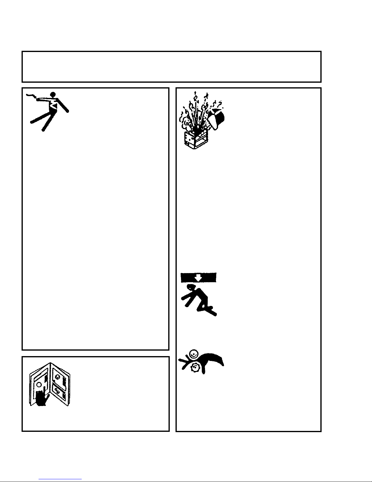
SAFETY
PROTECT YOURSELF AND OTHERS FROM SERIOUS INJURY OR DEATH. KEEP
CHILDREN AWAY. BE SURE THAT ALL INSTALLATION, OPERATION, MAINTENANCE
AND REPAIR PROCEDURES ARE PERFORMED ONLY BY QUALIFIED INDIVIDUALS.
EQUIPMENT DAMAGE
ELECTRIC SHOCK CAN KILL.
1) The equipment is not waterproof. Using
the unit in a wet environment may result
in serious injury. Do not touch equipment
when wet or standing in a wet location.
2) The unused connectors have power
on them. Always keep the unused
connectors covered with the supplied
protective panels. Operation of the
machine without the protective panels
may result in injury.
3) Never open the equipment without rst
unplugging the power cord or serious
injury may result.
1) Do not plug in the power cord with out
rst verifying the equipment is OFF and
the cord input voltage is the same as
required by the machine or serious
damage may result.
2) Always verify both the pinion and
wheels are fully engaged before
applying power or equipment damage
may occur.
3) Do not leave the equipment unattended.
POSSIBLE.
4) Verify the customer supplied power
connections are made in accordance
with all applicable local and national
electrical safety codes. If none exist, use
International Electric Code (IEC) 950.
5) Never remove or bypass the equipment
power cord ground. Verify the equipment
is grounded in accordance with al
applicable local and national electrical
safety codes. In none exist, use
International Electric Code (IEC) 950.
READ INSTRUCTIONS.
Read the instruction manual before
installing and using the equipment.
4) Remove from the work site and store in
a safe location when not in use.
FALLING EQUIPMENT
can cause serious
personal injury and
equipment damage.
Faulty or careless user installation is
possible. As a result, never stand or
walk underneath equipment.
MOVING PARTS can
cause serious injury.
1) Never try to stop the pinion from moving
except by removing power or by using
the STOP control.
2) Do not remove any protective panels,
covers or guards and operate
equipment.
2

HIGH FREQUENCY WARNINGS
SPECIAL PRECAUTIONS ARE REQUIRED WHEN USING PLASMA,
TIG OR ANY WELDING PROCESS THAT USES HIGH FREQUENCY
TO STRIKE AN ARC.
WARNING: HIGH FREQUENCY CAN EFFECT MACHINE
OPERATION AND THEREFORE, WELD QUALITY.
Read the precautions below before installing and using the equipment.
PRECAUTIONS:
1) Some plasma or welding cables are strong sources of high frequency interference.
NEVER lay a plasma or welding cable across the controls of the machine.
2) Always physically separate the plasma or welding cable leads from the machine
cables. For example, the plasma or welding cable leads should NEVER be bundled
with a pendant cable or the machine power cord. Maximize the separation between
any machine cables and the plasma or welding cables.
3) Strictly follow the grounding procedures specied for the plasma or welding unit.
NOTE: Some plasma and welding units produce exceptionally large amounts of high
frequency noise. They may require a grounding rod be driven into the earth within six
feet (2 meters) of the plasma or welding unit to become compatible with an automatic
cutting or welding process.
4) If the high frequency is produced using a spark gap, adjust the points so the gap is
as small as possible. The larger the gap, the higher the voltage and the higher the
interference.
5) Some plasma or welding units will inject high frequency interference into the AC
power line. Use separate power line branches whenever possible to power the plasma
or welding source and the machine. Do not plug them into the same outlet box.
6) High frequency noise may enter the machine through the plasma or welding supply
remote contactor leads. Some plasma and welding sources can produce noise spikes
of up to several thousand volts. These sources are not compatible with automated
cutting and welding equipment. It is recommended that the remote
contactor leads on these plasma or welding sources not be connected to the machine.
An alternate solution is to purchase a separate remote contactor isolation box.
3

CB-1P CIRCLE BURNER
INSTRUCTIONS AND PARTS MANUAL
TABLE OF CONTENTS
PAGE
5 ...... Introduction / Features
6-7..... Set-Up and Operation
8 ...... CWO-6210 Rotation Controls
9 ...... CWO-7621 CB-1P Power Source Controls
10 ..... CWO-3951 Plasma Controls
11 ..... Technical Data / Dimensions
12 ..... CBO-1020-NPS, CBO-1020- CB-1P Plasma Circle Burner / Exploded View
13 ..... CBO-1020-NPS, CBO-1020- CB-1P Plasma Circle Burner / Parts List
14 ..... CBO-1020-NPS, CB-1P Plasma Circle Burner / Wiring Diagram
15 ..... CBO-1670 Racking System / Exploded View / Parts List
15 ..... CWO-1685 Small Horizontal Racker / Exploded View / Parts List
16 ..... CWO-3004 Cam Shaft & Spacer Assembly / Exploded View / Parts List
16 ..... CWO-3005 5" Cam Assembly / Exploded View / Parts List
17 ..... CWO-3035 Junction Box Assembly / Parts List / Wiring Diagram
18 ..... CWO-3199 Housing Assembly / Exploded View / Parts List
19 ..... CWO-3418 Transmission / Exploded View / Parts List
19 ..... CWO-3422 P.M. Motor / Exploded View / Parts List
20 ..... CWO-3483 Shaft Assembly CB-1P / Exploded View / Parts List
20 ..... CWO-3516 CB-1P Pointer Assembly / Exploded View / Parts List
21 ..... CWO-3922 Manifold and Retainer / Exploded View / Parts List
21 ..... CWO-3923 CB-1P Large Brush Assembly / Exploded View / Parts List
22 ..... CWO-3941 High Frequency Brush / Exploded View / Parts List
22 ..... CWO-3945 CB-1P Small Brush Holder / Exploded View / Parts List
23 ..... CWO-3951 Plasma Control Box / Exploded View / Parts List
24 ..... CWO-3951 Plasma Control Box / Wiring Diagram
25 ..... CWO-6210 Rotation Control / Exploded View / Parts List
26 ..... CWO-6210 Rotation Control / Wiring Diagram / Electrical Component Chart
27 ..... Consolidated Wiring Diagram
28 ..... CWO-1050 120V Power Box / Wiring Diagram
29 ..... CWO-7655 Power Source Replacement Components
30 ..... Carriages
31 ..... Set-Up Instructions for CW-5 / CB-1P Used in Sprinkler Fabrication
32 ..... Set-Up Instructions for CW-5 / CB-1P used in Sprinkler Fabrication
33 ..... Set-Up Diagram for CW-5 / CB-1P Used in Sprinkler Fabrication
34 ..... Preventive Maintenance for CB-1P Plasma Circle Burner
37 ..... Warranty
4

INTRODUCTION:
The CB-1P (CBO-1020) Plasma Circle Burner was designed for plasma bevel cutting of one to
twelve inch diameter holes and will cut beveled holes in light wall pipe or vessels with wall thickness up to 5/16" (7 mm). An automatic rise and fall cam controls the torch position for saddle cut
holes up to 2/3 of work diameter. The cables and air hoses supplying the unit pass through slip
rings and O-rings enabling the machine to operate continuously in either direction without cable
or hose wrap up. The CB-1P (CBO-1020) Plasma Circle Burner is supplied with a Victor / Thermal
Dynamics (CutMaster 82) plasma power source, 180 degree plasma machine torch and 50' (15 m)
control cable / torch lead. The CB-1P (CBO-1020) Plasma Circle Burner requires both 220/50-60/1
and 120/50-60/1 to operate. The unit must be mounted on a carriage or xture.
FEATURES:
• 1/12 HP P.M. motor and rotational speed control
• 180 degree plasma machine torch
• 50 ft. (15 m) control cable / torch lead
• Adjustable vertical and horizontal torch positioning system
• Rise and fall cam assembly with 5" (125 mm) of travel
• Brushes and collector rings for plasma current, rated at 200 AMPS
• Brushes and collector rings for all controls, eliminates cable and hose wrap
• Plasma cutting power supply, CutMaster 82 Plus with duty cycles of 65% at 60 AMPS and
100% at 50 AMPS
• Rotation speed and directional controls
• Manual / Off / Automatic control switch
5

SET-UP AND OPERATION:
**All page numbers referred to in this section are from this manual unless otherwise specied.**
POWER SUPPLY:
®
The CB-1P Plasma Circle Burner is supplied with a modied Thermal Dynamics CutMaster
Plasma Cutting Power Supply. The power supply provides auxiliary power to the CB-1P Plasma Circle
Burner for the operation of switches, speed control, and the rotational drive. Refer to the Thermal
®
Dynamics CutMaster
82 Plus Plasma Cutting Power Supply operating manual #0-4979 supplied with
this machine for general operation and set-up information.
PLASMA CUTTING TORCH:
The CB-1P Plasma Circle Burner is equipped with a Thermal Dynamics Plasma Cutting Torch model
PCM-120 machine torch. Refer to the Thermal Dynamics Plasma Cutting Torch instruction manual #02818 supplied with this machine for general operation and set-up information.
FIXTURING:
All circle burners have to be xtured in some manner from the top of the shaft. This may be achieved in
one of the following: column & boom, manipulator, or carriage & monorail.
CABLE CONNECTIONS:
The CB-1P Plasma Circle Burner is equipped with a Junction Box Assembly (CWO-3035), shown on
page 17. The Junction Box Assembly is supplied with ve leads that need to be connected as described
below.
82 Plus
Connect:
• Plasma Box Cable Assembly to the terminal connector in the main gear at the top of the machine.
• Air Hose Assembly to the hose tting in the top of the CB-1P Shaft Assembly item (11) on page 13.
• Low Frequency Power Cable to the Low Frequency Power Cable.
• High Frequency Power cable to the High Frequency Power Cable.
• The Power Supply Torch Lead (air, control cable, high frequency)to the power supply.
• It is helpful to mount the Junction Box assembly to the top of the carriage or to the manipulator.
RISE AND FALL OF THE CAM:
CAM
All circle burners are equipped with a rise and fall cam assembly.
The cam assembly must be aligned before any other settings can
be made. To align the cam on the machine, align the horizontal rack
parallel to the pipe, then adjust the gun holder so it is perpendicular
to the horizontal rack. Loosen the set screws in the brass block
on the cam, and rotate the cam to the vertical position as shown.
SETTING THE CAM:
The cam setting is equal to the distance “B” subtracted from the
distance “A”.
HORIZONTAL RACK
EXAMPLE:
Let A=3 and B=2
3-2=1
The cam setting is 1.
6
B
A
B
A
TORCH
HOLDER
PIPE

WHEEL ADJUSTMENT:
The CB-1P Racking System (CWO-1670) and the Small Vertical Racker
(CWO-1685) are equipped with adjustable wheels. Always check these
components for proper wheel adjustment before using the machine. The
wheels need adjustment if you can cock or wiggle the components out of
alignment. The wheels should be snug but not prohibit movement along the
path of travel. The wheels with the hex stand off are adjustable. To adjust
the wheels loosen the hex bolt (A) until the adjustable bushing (B) can be
rotated. Correct the wheel alignment by rotating the adjustable bushing
(B). Once adjusted, hold the adjustable bushing (B) while tightening the
hex bolt (A). Recheck alignment.
B
MACHINE CONTROLS:
Operational parameters can be set using the two control boxes attached to the machine as well as the
controls located on the power supply. Please refer to the sections in this manual.
• CWO-3951 Plasma Controls for descriptions of the control capabilities.
• CWO-6210 Rotation Control for descriptions of the various speed and directional capabilities.
• CWO-7655 Power Source Controls for descriptions of the power supply controls.
A
MAKING A CUT:
1. Position the torch to the starting location using the Racking System (CWO-1670). Ensure that the
torch is at the appropriate position, standoff distance and angle.
2. Connect the ground cable to the work piece. The ground cable must make good electrical contact
with the work.
3. With the Arc “ON/OFF” switch in the “OFF” position and the “HAND/OFF/AUTO” switch in the
“HAND” position, set the rotation direction and speed.
4. With the Arc “ON/OFF” switch in the “ON” position the cutting process and rotation are both started
by throwing the “HAND/OFF/AUTO” switch to the “AUTO” position.
5. To stop the cutting processes and rotation, throw the “HAND/OFF/AUTO” switch to the “OFF”
position.
WARNING: THIS MACHINE PRODUCES PLASMA ARC RAYS, IT IS NECESSARY TO USE
CORRECT EYE, HEAD, AND BODY PROTECTION.
7
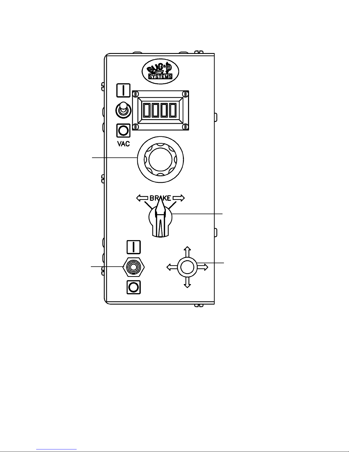
CWO-6210 ROTATION CONTROLS
SPEED
CONTROL
TRAVEL
DIRECTION
ON/OFF
SWITCH
PILOT LIGHT
SPEED CONTROL:
Controls the speed in which the machine travels. The depicted lines 0 to 100 should not be construed as
inches per minute of travel. They should be considered as reference points only.
TRAVEL DIRECTION:
Controls the direction in which the machine will travel. Select the left arrow for clockwise rotation, brake
for stop, and the right arrow for counter-clockwise rotation.
ON / OFF SWITCH:
The On / Off switch enables / disables power to the rotation control box.
PILOT LIGHT:
The Pilot Light indicates whether the machine is on / off as dictated by the on / off switch.
8

CWO-7655 CB-1P POWER SUPPLY CONTROLS
1
2
43
Thermal Dynamics, Art# A-07886
6
5
7
9
8
10
1. OUTPUT CURRENT CONTROL
The Current Control is used to set the desired output current, the current can be adjusted from 15-60
amps. For drag cutting applications, the current should not exceed 60 amps.
2. FUNCTION CONTROL
The Function Control knob is used to select between four operating modes -- Set, Run, Rapid Auto
Restart, and Latch. SET is used for setting gas pressure and purging lines. RUN is used for torch
operation. RAPID AUTO RESTART allows for faster restarting of the Pilot Arc for uninterrupted
cutting. The LATCH is used for specic applications, generally hand held cuts.
3. ON / OFF POWER SWITCH:
Controls input power to the power supply. Up is ON, down is OFF.
4. AIR / GAS PRESSURE CONTROL:
Used in the SET mode to adjust the air/gas pressure. Pull knob out to adjust, then push in to lock.
5. AC INDICATOR:
Steady light indicates power supply is ready for operation. Blinking light indicates interlock mode.
Refer to power supply operation manual for more instructions.
6. TEMP INDICATOR:
Indicator will light when power supply internal temperature is above the normal operational limits. Let
unit cool before continuing operation.
7. GAS INDICATOR:
Indicator will light when minimum input gas pressure for power supply operation is present. This may
not be enough pressure for torch operation.
8. DC INDICATOR:
Indicator will light while the torch switch is pressed.
9. FAULT ERROR INDICATOR:
Indicator is ON when fault circuit is active. Refer to power supply operation manual for more
instructions.
10. PRESSURE INDICATORS:
Indicator will light according to pressure that was set using Pressure Control Knob.
9

CWO-3951 PLASMA CONTROLS
ARC ON/OFF
HAND/OFF/AUTO
ARC ON/OFF:
The OFF position disables the cutting process, allowing machine rotation without starting the cutting process
when the HAND/OFF/AUTO switch is thrown to the HAND position. The ON position enables the cutting
process when the HAND/OFF/AUTO switch is thrown to the AUTO position.
HAND/OFF/AUTO:
The HAND position allows the operator to rotate the machine when the ARC ON/OFF switch is in the OFF
position to check torch position as well as the cam setting. The AUTO position will start the entire cutting
operation based on the operator’s settings including machine rotation when the ARC ON/OFF switch is in
the ON position. The OFF position will stop the entire cutting process including machine rotation.
10
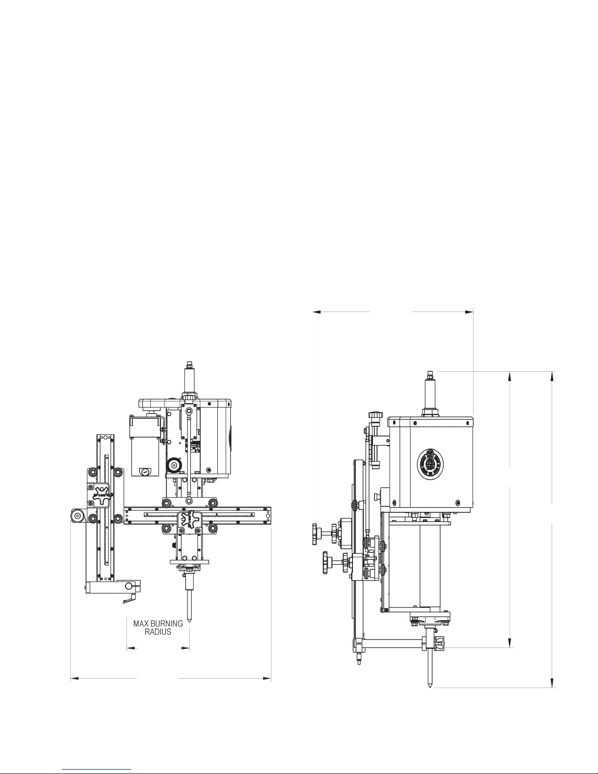
TECHNICAL DATA
Amperage: 15-60 AMPS
Input Voltage: 208/440 VAC 50/60 Hz single or three phase
120 VAC 50/60 Hz single or three phase
Rotation Speed: 0.2-11 rpm
Cam Range: 5" (125 mm)
Burning Diameter: 1-12" (25-300 mm)
Machine Weight: 170 lbs. (77 kg)
Power Source Weight: 73.5 lbs. (33 kg)
Shipping Weight: 283.5 lbs. (129 kg)
DIMENSIONS:
20"
(508 mm)
30"
(762 mm)
34"
(864 mm)
6"
(152 mm)
26"
(660 mm)
11

CBO-1020-NPS, CBO-1020- CB-1P PLASMA CIRCLE BURNER / PARTS LIST
24
23
36
9
7
14
30
18
8
27
32
34
29
12
21
5
22
11
20
4
3
6
2
28
1
38
32
34
35
33
37
10
15
17
19
16
31
39
40
12
25, 26
13
41

CBO-1020-NPS, CBO-1020- CB-1P PLASMA CIRCLE BURNER / EXPLODED VIEW
ITEM QTY PART NO. DESCRIPTION
1 1 CBO-1670 Racking System
2 1 CWO-1685 Small Horizontal Racker
3 1 CWO-3004 Cam Shaft & Spacer Assembly
4 1 CWO-3005 5" Cam Assembly
5 1 CWO-3199 Housing Assembly
6 1 CWO-3399 Load Spring Assembly
7 1 CWO-3417 Motor & Transmission Plate Assembly
8 1 CWO-3418 Transmission
9 1 CWO-3422 P.M. Motor 157
10 1 CWO-3466 Slide Bar Mounting Assembly
11 1 CWO-3483 Shaft Assembly CB-1P
12 1 CWO-3484 CB-1P Collector Ring Assembly
13 1 CWO-3516 CB-1P Pointer Assembly
14 1 CWO-3922 Manifold & Retainer Assembly
15 1 CWO-3923 CB-1P Large Brush Assembly
16 1 CWO-3933 26" Air Hose Assembly
17 1 CWO-3955 Terminal Block Assembly
18 1 CWO-3941 High Frequency Brush Assembly
19 1 CWO-3945 CB-1P Small Brush Holder
20 1 CWO-3951 Plasma Control Box
21 1 CWO-4050 1" Bearing w/Fasteners
22 1 CWO-4060 1-1/4" Bearing w/Fasteners
23 1 CWO-5075 1-1/4" ID Trantorque
24 1 CWO-5220 Guard Assembly
25 1 CWO-6210 Rotation Control Box
26 1 CWO-6110-L Rotation Control Mounting
27 1 CWO-6423 CB-1P Control “L” Bracket
28 1 CWO-6424 CB-1P Control MT. Spacer
29 1 CWO-6426 Plasma Control MT. Bracket
30 1 CWO-9037 CB-1P 7-1/8" Diameter Gear
31 1 CWO-9482 Centering Head Tool
32 4 FAS-0356 Hex Hd Cap Scr 1/4-20 x 5/8"
33 2 FAS-0379 Hex Hd Cap Scr 5/16-18 x 1"
34 4 WAS-0243 1/4" Split Lock Washer
35 2 WAS-0251 5/16" Split Lock Washer
36 1 CWO-4849 Motor Mt. Plt. Insulator
37 1 CWO-4848 Trans. Plate Insulator
38 1 CWO-3035 Junction Box Assy. Plasma
39 1 CWO-3939 Manifold Power Cable
40 1 CWO-3957 Low Frequency Power Cable
41 1 CWO-3958 Hight Frequency Power Cable
Note: 1. See CBO-1020-NPS for wiring and cable information. (Page 14)
2. CWO-3934 is the plasma replacement torch. (Page 29)
13

CBO-1020-NPS CB-1P PLASMA CIRCLE BURNER / WIRING DIAGRAM
14
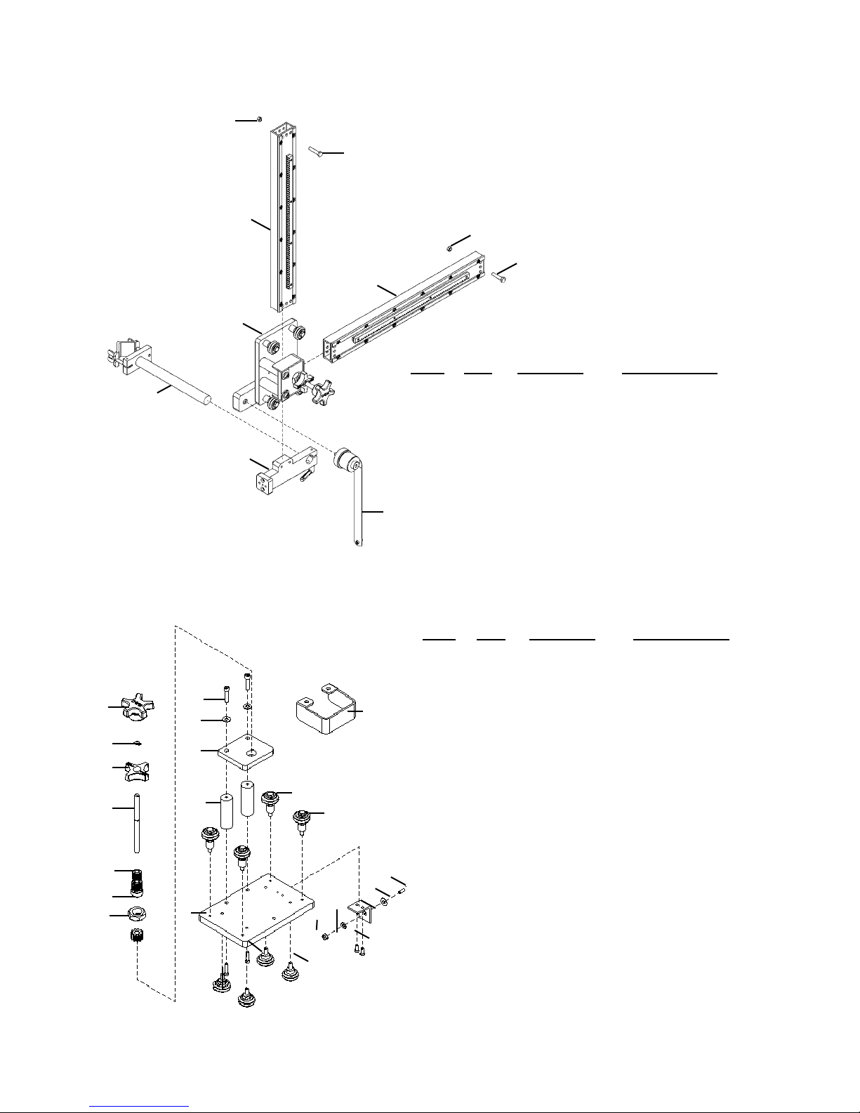
CBO-1670 RACKING SYSTEM / EXPLODED VIEW / PARTS LIST
6
7
1
6
7
1
2
ITEM QTY PART NO. DESCRIPTION
5
3
1 2 ABR-1070 V-Guide Ways 19"
2 1 CWO-1675 Vertical Racker
3 1 CWO-1695 Attachment Block
4 1 CWO-3450 10.6# Load Spring Assy.
5 1 CBO-1675 Torch Clamp Assy.
6 2 FAS-1351 Hex Nut 1/4-20
7 2 FAS-2351 Hex Hd Cap Scr 1/4-20 x 1-1/4"
4
CWO-1685 SMALL HORIZONTAL RACKER / EXPLODED VIEW / PARTS LIST
ITEM QTY PART NO. DESCRIPTION
1 1 BUG-2032 Knob, Black
2 1 CWO-1678 Racker Plate
3 1 CWO-1679 Pinion 11T
1
19
16
17
15
13
23
20
2
18
F
A
3
6
F
A
A
7
4
F
A
14
F
12
8
5
21
22
11
4 2 CWO-1680 W2 Fixed Leg & Wheel Assy.
5 2 CWO-1681 W2 Adj. Leg & Wheel Assy.
6 1 CWO-1686 Mount Plate (Small Racker)
7 2 CWO-4020 Fixed Leg & Wheel Assy.
8 2 CWO-4021 Adj. Leg & Wheel Assy.
9 1 CWO-4112 Bracket
10 1 FAS-0355 Hex Hd Cap Scr 1/4-20 x 1/2"
11 2 FAS-0534 Soc Hd Cap Scr 10-24 x 3/8"
12 4 FAS-0557 Soc Hd Cap Scr 1/4-20 x 3/4"
13 1 FAS-1307 Hex Jam Nut 3/4-16
14 1 FAS-1351 Hex Nut 1/4-20
15 1 MUG-1141 Bearing Collet
16 1 MUG-1142 Knob, Locking
10
17 1 MUG-1144 Shaft
20
9
18 2 MUG-1453 Stand-Off
19 1 MUG-1579 Retaining Ring
20 3 WAS-0240 1/4" SAE Washer
21 1 WAS-0243 1/4" Split Lock Washer
22 1 CWO-1671 Racker Shield
23 2 FAS-0559 Soc Hd Cap Scr 1/4-20 x 1"
F = Fixed Wheel Placement
A = Adjustable Wheel Placement
15

CWO-3004 CAM SHAFT & SPACER ASSEMBLY / EXPLODED VIEW / PARTS LIST
5
2
9
7
4
8
6
3
1
ITEM QTY PART NO. DESCRIPTION
1 1 CWO-4073 Ball Joint Rod End 5/16-24 RH
2 1 CWO-5019 Ball Joint Rod End 5/16-24 LH
3 1 CWO-9078 Spacer 1/2" O.D. x 5/16 I.D. x 3/4"
4 1 CWO-9357 Cam Shaft Tube
5 1 FAS-0377 Hex Hd Cap Scr 5/16-18 x 3/4"
6 1 FAS-1380 Hex Nut 5/16-24
7 1 FAS-1381 Hex Nut 5/16-24 LH
9
8 1 FAS-2375 Hex Hd Cap Scr 5/16-18 x 2"
9 3 WAS-0250 5/16 SAE Washer
9
CWO-3005 5" CAM ASSEMBLY / EXPLODED VIEW / PARTS LIST
2
1
10
12
13
4
5
7
4
11
1
8
16
6
13
ITEM QTY PART NO. DESCRIPTION
1 2 BUG-2098 Delrin Washer 3/8" I.D.
2 1 BUG-9012 Locking Collar
3
3 1 CWO-4026 Base Plate 5" Cam
4 2 CWO-4027 End Plate 5" Cam
5 1 CWO-4028 Center Block 5" Cam
6 1 CWO-4029 Screw 5" Cam
7 2 CWO-4031 Rod 5" Cam
8 1 CWO-4032 Knob
9
9 1 CWO-5199 Scale
10 4 FAS-0434 Set Scr 10-24 x 3/8"
11 1 FAS-0444 Set Scr 10-32 x 3/8"
12 2 FAS-0495 Set Scr 3/8-16 x 1/2"
13 4 FAS-0534 Soc Hd Cap 10-24 x 3/8"

CWO-3035 JUNCTION BOX ASSEMBLY / PARTS LIST / WIRING DIAGRAM
ITEM QTY PART NO. DESCRIPTION
1 1 CWO-3033 Cable Assy., Plasma Box
2 1 CWO-3933 20" Oxygen Hose Assy.
3 1 CWO-3938 Hose Coupling Assy.
4 1 CWO-3957-24 24" Low Frequency Power Cable
5 1 CWO-3958-24 24" High Frequency Power Cable
6 1 CWO-6288 Terminal Block (6)
7* 1 CWO-6771 Machined Enclosure & Cover
8 1 CWO-6772 JB Support Block
9* 2 CWO-6767 Cord Grip 1-1/4 Wire
10 4 FAS-0235 Rnd Hd Scr 10-24 x 1/2"
11* 4 FAS-0527 Soc Hd Cap Scr 8-32 x 3/4"
12 1 FAS-0359 Hex Hd Cap Scr 1/4-20 x 1"
13* 2 FAS-0915 Flt Hd Soc Scr 6-32 x 1/2"
14* 2 FAS-1310 Hex Nut 6-32
15 2 FAS-1351 Hex Nut 1/4-20
16 1 FAS-2351 Hex Hd Cap Scr 1/4-20 x 1-1/4"
17 2 WAS-0240 1/4" SAE Washer
18 2 WAS-0243 1/4" Split Lock Washer
* NOT SHOWN FOR CLARITY
17
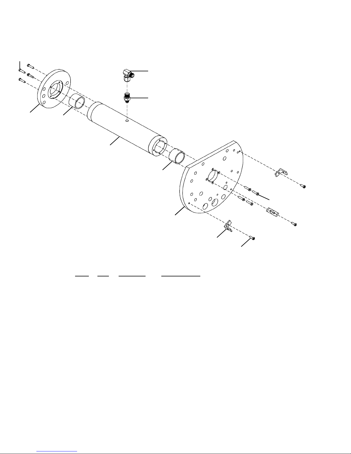
CWO-3199 HOUSING ASSEMBLY / EXPLODED VIEW / PARTS LIST
9
1
2
5
6
3
6
9
4
7
8
ITEM QTY PART NO. DESCRIPTION
1 1 BUG-1296 90 Degree Hose Adaptor
2 1 CWO-4226 Outlet Bushing
3 1 CWO-5837 Center Tube Housing
4 1 CWO-5843 Top Housing Plate CW-5
5 1 CWO-5846 Lower Housing Plate CW-5
6 2 CWO-5975 Insert 1-5/8" O.D. x 1.376" I.D. x 1"
7 3 CWO-9339 Angle For Guard
8 3 FAS-0535 Soc Hd Cap Scr 10-24 x 1/2"
9 8 FAS-0548 Soc Hd Cap Scr 10-32 x 3/8"
18

CWO-3418 TRANSMISSION / EXPLODED VIEW / PARTS LIST
ITEM QTY PART NO. DESCRIPTION
1 1 CWO-3276 Pinion Gear Assembly
2 1 CWO-4068 Transmission SW 3.5:1
2
1
CWO-3422 P.M. MOTOR / EXPLODED VIEW / PARTS LIST
2
4
3
1
ITEM QTY PART NO. DESCRIPTION
1 1 CWO-4069 Gear, P.M. Motor
2 1 CWO-4147 P.M. Motor Bracket #970
3 1 CWO-5997 P.M. Motor
4 3 TERM-WTE-1508 #8 Fork Blue 14RB-8FL T&B
19

CWO-3483 SHAFT ASSEMBLY CB-1P / EXPLODED VIEW / PARTS LIST
1
2
3
O-Ring Groove
O-Ring Groove
ITEM QTY PART NO. DESCRIPTION
2
4
1 1 BUG-9096 Outlet Bushing Oxygen
2 2 CWO-4202 O-Ring CB-1P N70 568 322 1-1/4
3 1 CWO-5781 Shaft
4 1 CWO-5975 Insert 1-5/8" O.D. x 1.376 x 1"
CWO-3516 CB-1P POINTER ASSEMBLY / EXPLODED VIEW / PARTS LIST
3
2
1
ITEM QTY PART NO. DESCRIPTION
1 1 CWO-4238 CB-1P Center Pin
2 1 CWO-9131 Compression Spring
3 1 FAS-0559 Soc Hd Cap Scr 1/4-20 x 1"
20

CWO-3922 MANIFOLD AND RETAINER / EXPLODED VIEW / PARTS LIST
5
2
8
12
10
3
ITEM QTY PART NO. DESCRIPTION
1 1 CWO-3938 Hose Coupling Assembly
2 1 CWO-6777 Coaxial Panel Recp. Assembly
4
6
1
11
9
3 1 CWO-9027 1/2" Support Plate
4 1 CWO-9028 1/8" Support Plate
5 4 FAS-0102 Pan Hd Scr 4-40 x 1/4"
6 2 FAS-0235 Rnd Hd Scr 10-24 x 1/2"
7 1 FAS-0357 Hex Hd Cap Scr 1/4-20 x 3/4"
8 2 FAS-0359-N Hex Hd Cap Scr 1/4-20 x 1"
9 1 FAS-1351 1/4-20 Hex Nut
10 1 WAS-0240 1/4" SAE Washer
11 1 WAS-0243 1/4" Split Lock Washer
12 2 BUG-2063 1/4" Delrin Washer
7
CWO-3923 CB-1P LARGE BRUSH ASSEMBLY / EXPLODED VIEW / PARTS LIST
8
9
4
2
1
6
10
11
7
7
11
3
5
ITEM QTY PART NO. DESCRIPTION
1 1 CWO-7624 Large Brush Holder Support
2 1 CWO-3266 Attachment Bar
3 1 CWO-3263 Large Brush Holder
4 2 CWO-3264 Spring Clip
5 2 CWO-4337 Large Brush 1-1/2" x 3/4" x 2"
6 1 CWO-5550 Micarta Bushing
7 2 FAS-0305 Hex Hd Cap Scr 1/2-13 x 2"
8 1 FAS-0357 Hex Hd Cap Scr 1/4-20 x 3/4
9 1 WAS-0243 1/4" Split Lock Washer
10 1 WAS-0280 1/2" SAE Flat Washer
11 2 WAS-0281 1/2" Split Lock Washer
21

CWO-3941 HIGH FREQUENCY BRUSH / EXPLODED VIEW / PARTS LIST
1
2
6
3
8
9
4
7
5
ITEM QTY PART NO. DESCRIPTION
1 1 CWO-5833 Brush 3/4" Sq. x 3/4" LG.
2 1 CWO-5849 Brush Holder, 3/4" Sq. Brush
3 1 CWO-7625 Hi-Freq. Brush Holder Support
4 1 FAS-2355 Hex Hd Cap Scr 1/4-20 UNC x 2"
5 1 FAS-2393 Hex Hd Cap Scr 3/8-16 x 1-1/2"
6 1 WAS-0260 3/8" Washer
7 1 WAS-0262 3/8" Split Lock Washer
8 1 WAS-0240 1/4" Washer
9 1 WAS-0243 1/4" Lockwasher
CWO-3945 CB-1P SMALL BRUSH HOLDER / EXPLODED VIEW / PARTS LIST
Orange
ITEM QTY PART NO. DESCRIPTION
1 1 CWO-3464 Small CB-1P Retainer Assembly
2 1 CWO-9076 Retainer Support (Small)
1
5
6
4
3
3 2 FAS-0539 Soc Hd Cap Scr 10-24 x 1" LG
4 1 FAS-2551 Soc Hd Cap Scr 1/4-20 x 1-1/4" LG
5 1 WAS-0240 1/4" SAE Washer
6 1 WAS-0243 1/4" Split Lock Washer
2
7 5 CWO-5831 1/8" x 1/8" x 7/8" LG Brush
8 5 CWO-5874 1/8" Brush Holder
9 5 CWO-5875 Cap
10 5 CWO-5876 Clip
11 1 CWO-7609 CB-1P Small Brush Retainer
12 5 TERM WTE 0602 #6 Fork Blue
7, 8, 9, 10
22
11
12

CWO-3951 PLASMA CONTROL BOX / EXPLODED VIEW / PARTS LIST
6
9
5
10
4
7
8
1
6
3
ITEM QTY PART NO. DESCRIPTION
1 1 BUG-2255 Toggle Switch
2 1 BUG-2287 Power Receptacle
3 1 CWO-5672 Cover Face Plate
4 1 CWO-6207 Toggle Switch On-Off
5 1 CWO-6288 Terminal Block
6 1 CWO-6367 Plasma Control Box
7 2 FAS-0115 Pan Hd Scr 6-32 x 1/2"
8 2 FAS-1310 Hex Nut 6-32
9 2 GOF-3021 Press Nut
10 2 WAS-0211 #6 Star Lock Washer
2
23

CWO-3951 PLASMA CONTROL BOX / WIRING DIAGRAM
24

CWO-6210 ROTATION CONTROL / EXPLODED VIEW / PARTS LIST
3
20
19
22
12
2
13,14,21
6
15,17
14
15,16
21
29
23
14
8
10
21
18
1
11
9
13
13
21,14,13
24
7
5
27
28
4
25,26
29
ITEM QTY PART NO. DESCRIPTION
1 1 ARM-2279 TOGGLE SWITCH
2 1 BUG-9445 POWER CORD
3 1 CON-PS04M PLUG, STRAIGHT 4-PIN MALE
4 1 BUG-9687 KNOB FLUTED
5 1 BUG-9694 KNOB
6 2 CSR-WTE-1597 CORD STRAIN RELIEF
7 1 CWO-6216 ROTATION BOX FRONT PANEL
8 1 CWO-5547B ROTATION BOX REAR PANEL
9 1 CWO-6206 INDICATOR LIGHT
10 1 CWO-6527 0-90V SPD CTRL w/ISOLATOR
11 1 CWO-6839 ROTATION CONTROL CASE
12 1 CWO-6802 ROTATION BOX COVER
13 6 FAS-0115 #6-32 X 1/2" PAN HEAD ZINC
14 6 FAS-1310 HEX NUT 6-32
15 2 FHO-0188 FUSE HOLDER
16 1 FUS-0190 FUSE 1.5 AMP
17 1 FUS-0257 FUSE 3 AMP
18 1 MUG-1258-1 ROTARY SWITCH ASSEMBLY
19 10 SCW-WTE-0264 #6-32 X 1/4" SHT MT SCR
20 3 TERM-WTE-0197 #6 RED FORK
21 6 WAS-0211 #6 INTERNAL STAR WASHER
22 42" WRE-WTE-0501 18/3 SJO 300V CORD
23 1 MUG-1589 HOLE PLUG .500"
24 1 BUG-1562 MULTI-TURN POTENTIOMETER
25 4 FAS-0401 #4-40 X 3/8" PAN HD
26 4 SCF-1001 #4-40 SELF CLINCHING NUT
27 1 BUG-1764 METER DISPLAY BOARD
28 1 MDS-1011 DISPLAY BEZEL
29 6 BUG-3331 HOLE PLUG 1/4"
25
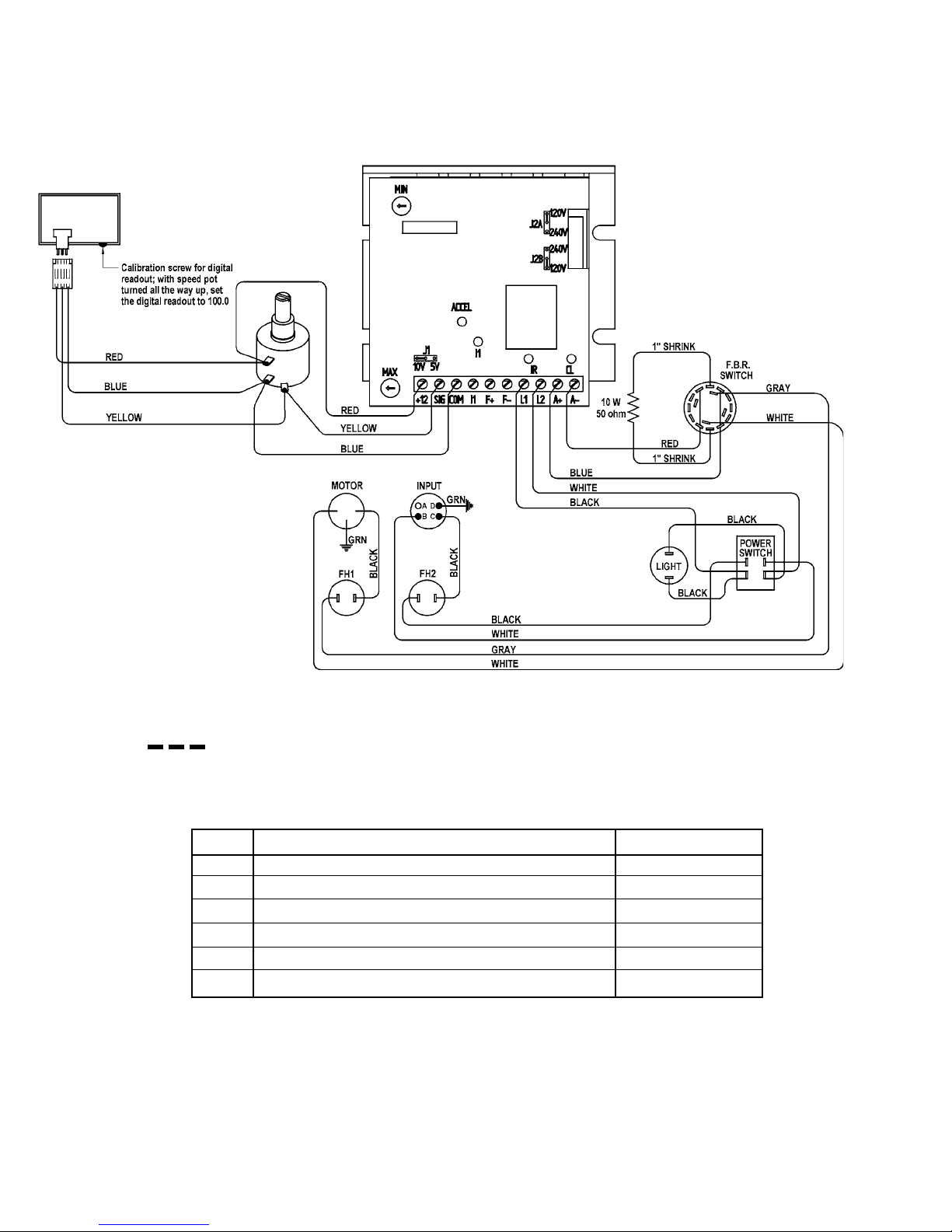
CWO-6210 ROTATION CONTROL / WIRING DIAGRAM / ELECTRICAL
COMPONENT CHART
3
6
2
4
5
= INDICATES ITEMS THAT ARE SUPPLIED TOGETHER.
ELECTRICAL COMPONENT CHART
ITEM DESCRIPTION PART NO.
1 TOGGLE SWITCH ARM-2279
2 RED NEON LAMP CWO-6206
3 SPEED CONTROL BOARD W/RESISTOR CWO-6525
4 FUSE 1.5 AMP FUS-0190
5 FUSE 3 AMP FUS-0257
6 ROTARY SWITCH MUG-1258-1
1
26
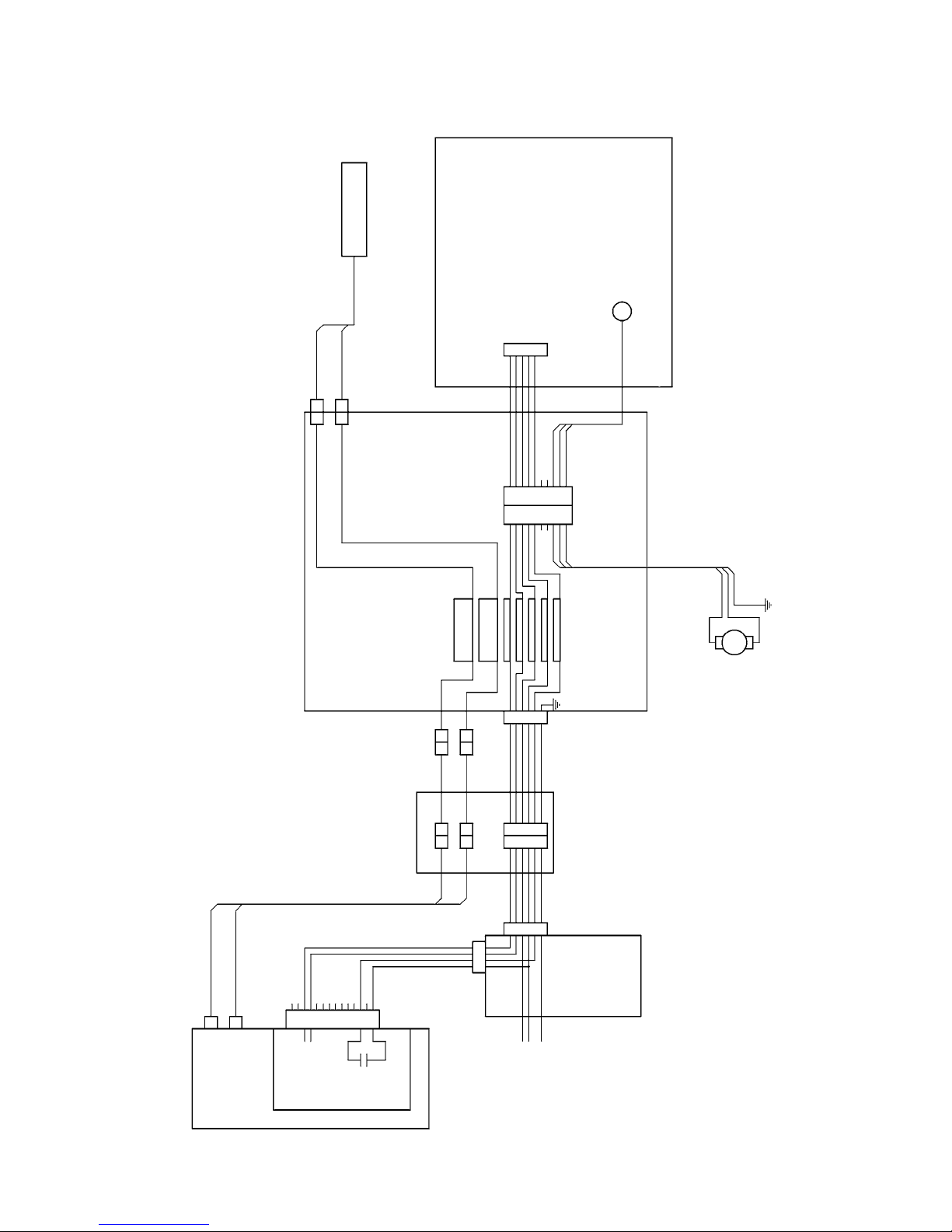
CONSOLIDATED WIRING DIAGRAM
ORANGE
ARC ON/OFF
CWO-3951 PLASMA CONTROL BOX
LOW FREQ
CB-1P
TORCH
HIGH FREQ
MODE SWITCH
MANUAL
OFF
AUTO
ORANGE
RED
WHITE
ORANGE
RED
WHITE
GREEN
ORANGE
RED
WHITE
MANUAL
OFF
AUTO
BROWN
BLUE
BLACK
BLACK
BLUE
BLACK
BLUE
BLACK
WHITE
WHITE
BLACK
GREEN
GREEN
2 WHITE
PLUG AC FEMALE
BLACK 1
GREEN
SWITCHED
AC POWER TO
ROTATION BOX
CWO-6110
ROTATION CONTROL
MOTOR
WIRES
WHITE
BLACK
GREEN
HIGH FREQ
LOW FREQ
123456789
1011121314
SLIP RINGS
LOW FREQ
LARGE
CONNECTORS
LOW FREQ
JUNCTION BOX
LOW FREQ
HIGH FREQ
HIGH FREQ
D
C
B
A
HIGH FREQ
A BC D E
ORANGE BA
ORANGE
A BC D E
RED B
WHITE C
RED
WHITE
WHITE
F
BLACK D
BLUE E
GREEN F
BLACK
BLUE
GREEN
F
BLACK
GREEN
POWER
SWITCH
FUSE, FILTER
AND PILOT
LIGHT NOT
SHOWN
MOTOR
SIMPLIFIED SMALL
POWER BOX
TRIGGER
PLASMA
THERMADYNE
PACKMASTER 75XL
PLUS
POWER
SOURCE
CONTROL
SWITCH
OK TOMOVE
CONTACT
AC
POWER
IN
27

CWO-1050 120V POWER BOX / WIRING DIAGRAM
28
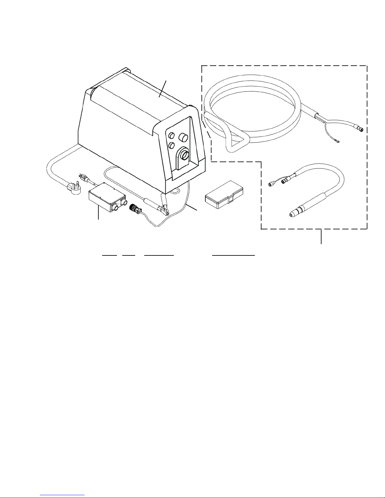
POWER SUPPLY REPLACEMENT COMPONENTS
2
3
4
ITEM QTY PART NO. DESCRIPTION
1 1 CWO-7596-50-CB-1P 50ft Machine Torch Hypertherm
2 1 CB-1P Plasma Power Source
3 1 CWO-1045-3 Plasma CB-1P Interface Cable
4 1 CWO-1050 120V Power Box
Note: For consumable chart, see Powermax 65 or 85 instruction manual.
1
29
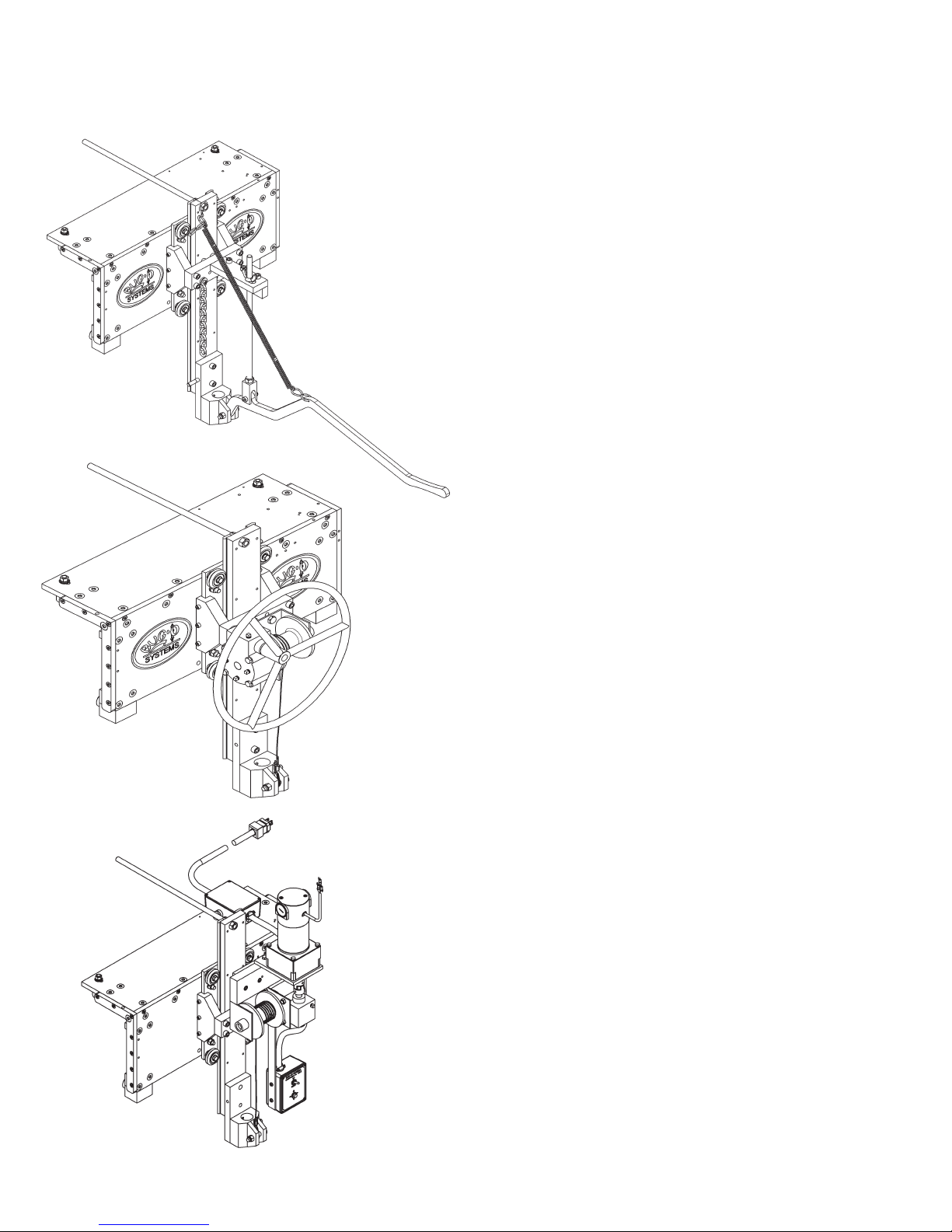
CARRIAGES
CWO-4530 151 Carriage
The 151 Carriage mounts on a standard monorail.
The carriage allows the operator to move the machine the length of the pipe, while utilizing a lever to
position the machine vertically on the work piece.
CWO-4540 151P Carriage
The 151P Carriage mounts on a standard monorail.
The carriage allows the operator to move the machine the length of the pipe, while utilizing a winch
to position the machine vertically on the work piece.
CWO-4550 151M Carriage
The 151M Carriage mounts on a standard monorail, or “bridge crane” type setups. The carriage
allows the operator to move the machine the
length of the pipe, while utilizing an electric motor
to mechanically position the machine vertically
on the work piece.
30

SET-UP INSTRUCTIONS FOR CW-5 / CB-1P USED IN SPRINKLER FABRICATION
SUPPORTING FIXTURE AND PIPE STANDS
The rst priority should be given to where the xture is to be placed. The burning of the holes and welding of the
couplings should be the last part of the operation performed on the pipe. It is important that a ow pattern or line be
looked at, so that when the pipe is taken out of the xture, it is nished and ready for shipment.
The mono rail consists of a 4" x 8" x 1/4" wall rectangular tubing with a 3/8" x 3" at bar welded to the tubing (See
pg. 30). The at bar has to project 1" above the top of the tubing. “C” clamps are to be used to hold the at bar
against the tubing with no gaps. The “C” clamp may be walked down the tubing as it is being tack welded. If the
beam has a bow greater than 1/32" in a 30' span, take to following steps:
1. Determine exactly where the center of the bow is. This may be accomplished by putting a string along
the front side of the monorail. Place 1/2" nuts between the string and the monorail and measure the
gap between the string and the monorail. Always measure on the same side of the string.
2. After you have determined where center of the bow is, take a hand torch and heat the outside of the
bow. The outside of the bow should be the side the at bar is welded to. Take a piece of chalk
and draw a triangle with a 2" base under the bottom of the at bar with the top or point of the triangle
pointing down. Do the same on the top of the monorail against the at bar with the top or point pointing
towards the face of the monorail. Heat these two areas so that they become cherry red in color. After
the heat has been applied, take a large rag and a bucket of water and cool the heated area. After the
area has been cooled, check the beam again. Repeat as necessary.
PIPE STANDS
The pipe stands consist of 3" pipe in oor anges with a 2-1/2" or 3" angle welded to the top of the pipe, and they
should be spaced and aligned as shown (See pg. 30). The two stands should have some sort of clamping device
to hold the pipe in place. The clamping device can be anything from a pipe vise to a chain and boom. The clamping
device must be staggered.
After the pipe stands and supporting columns are in place, the monorail is to be placed on the supporting columns.
The pipe stands and the supporting columns must be level and plumb. These items may have to be shimmed. With
these items level, the monorail may be put in place on the supporting columns and held in place by two “C” clamps.
Put a level on the face of the beam in the vertical position and on the bottom in the horizontal position. The beam
should be level both ways, and if not, the beam will have to be shimmed. If the monorail has a twist, which may
occur, level one end so that the other end needs to be pulled back.
Next, put a piece of 8" pipe in the pipe stands and clamp down. Take a centering head and nd the center of the
pipe on each end and in the middle. You can now use two methods to check to see if the monorail is aligned with
the pipe below. They are as follows:
1. Use a plumb bob off the face of the monorail and measure from the center of the pipe to the plumb bob.
The distance should be 5-11/16" in all three locations.
2. The second method is to put one carriage on the monorail and attach the CB-1P to it. With the center
pin in the burning machine, check all three locations. The burning machine must be plumb on the
carriage if this method is used.
31

SET-UP INSTRUCTIONS FOR CW-5 / CB-1P USED IN SPRINKLER FABRICATION
INSTALLING CARRIAGES AND MACHINES ON THE MONORAIL
Assemble carriages and put them on the rail.
The CW-5 welder is put on the carriage that is nearest to the welding power source and the CB-1P cutter nearest to
the plasma power source.
Put the CB-1P cutter machine on the 8" pipe in the stands and bring the carriage to the machine. Lower the shaft
coupling over the main shaft on the cutter. Ensure that shaft is fully inserted into the shaft coupling. Rotate the machine
so that the plasma leads are in front and parallel to the carriage and tighten the set screws in the shaft coupling to
secure the main shaft to the vertical slide assembly.
Next put the CW-5 welder on the 8" pipe and bring its carriage to it. Lower the shaft coupling down over the main
shaft. Rotate the machine so that the welding lead on top of the machine will be on your left. This will put the electrical
connector on the right. Tighten the set screws in the shaft coupling to secure the main shaft to the vertical slide assembly.
It is important for the machines to hang plumb. Left to right adjustments are made by loosening the two bolts that
connect the shaft coupling to the vertical rail. Front to back adjustments are done by adjusting the position of the
vertical rail support plate. Move the plate by adjusting the eight nuts on the four studs.
Note: Once machines are plumb verify that the machines are centered over the pipe stand.
CARRIAGE ADJUSTMENT:
FRONT TO BACK ADJUSTMENT
FRONT TO BACK ADJUSTMENT
VERTICAL RAIL
FRONT TO BACK ADJUSTMENT
VERTICAL RAIL SUPPORT PLATE
FRONT TO BACK ADJUSTMENT
LEFT TO RIGHT ADJUSTMENT
32
SHAFT COUPLING

1" (25 MM)
(135 MM)
5.31"
(19 X 152 X 660 MM)
3/4" X 6" X 26" BAR
1/8" X 1" (3X25 MM)
TACK WELD
1-1/2" (38 MM)
& BOTTOM
MM) CENTERS TOP
LONG ON 16" (406
PIPE
22"
(559
MM)
30" (762 MM)
1-1/2" (38 MM) PIPE
CABLES AND HOSES
SWIVEL EYES TO SUPPORT
10 HARNESS SNAPS WITH
(76 MM) FLAT BAR
LENGTH OF PIPE + 6' (1.83 M)
3/8" (9.5 MM) X 3"
36" (914 MM)
5" PIPE
WELDER
8" PIPE
RECTANGULAR TUBING
(102 X 203 X 6 MM) WALL
4" X 8" X 1/4"
40" (1 M)
PIPE VISE
(1.5 M)
5'
WELDING POWER SOURCE
(1.8 M)
6'
(2.4 M)
8'
SET-UP DIAGRAM FOR CW-5 / CB-1P USED IN SPRINKLER FABRICATION
EYE BOLT
CABLE
1/4" (6 MM)
BURNER
8" (203 MM)
76" (2 M)
PIPE
(76 MM)
3"
FLANGES
CAST IRON
(1.8 M)
6'
(1.5 M)
5'
PLASMA POWER SOURCE
33

PREVENTIVE MAINTENANCE FOR CB-1P PLASMA CIRCLE BURNER
CAUTION: Make sure the input power at the power source is turned off and the high and low
frequency power cables, and the 50' control cable (Items # 2, 3,10, on the CB-1P Electrical Wiring Diagram) are disconnected from the circle burner prior to working inside the machine.
POWER SUPPLY: Refer to the Thermal Dynamics Cut Master 82 Plus Plasma Cutting Power
Supply operating manual # 0-4979 supplied with this machine for general maintenance procedures and replacement parts.
PLASMA TORCH: Refer to the Thermal Dynamics Plasma Cutting Torch model PCM-102 machine torch instruction manual # 0-2818 supplied with this machine for general maintenance
procedures and replacement parts.
AFTER DAILY USE:
Refer to CB-1P Exploded View / Parts List. (Page 13)
Racking System Item # 1: Inspect gear rack; hardened ways and wheels (remove all dirt,
grease, and rust). Check hardened ways for nicks and replace if necessary. Lubricate with a dry
spray lubricant. Adjust wheels for snug t and smooth operation. Lubricate racker pinion with a
dry Teon or graphite spray lubricant.
Small Vertical Racker Item # 2: Inspect wheels (remove all dirt, grease, and rust). Adjust
wheels for snug t and smooth operation. Lubricate racker pinion and wheels with a dry Teon or
graphite spray lubricant.
Slide Bar Mounting Assembly Item # 10: Inspect hardened ways (remove all dirt, grease, and
rust). Check hardened ways for nicks and replace if necessary.
Refer to CB-1P Electrical Wiring Diagram. (Page 14)
Control Cable Item # 10: Inspect cable connector to make sure threads are not stripped and
that the connector is not cracked. Check the cable for cuts, missing insulation, and burn spots
replace if necessary.
CB-1P Collector Ring Item # 9: Inspect cable connector to make sure threads are not stripped
and that the connector is not cracked. Ensure that the connector is fastened properly to the large
aluminum gear (item # 30, page 12).
34

EVERY SIX MONTHS:
Refer to CB-1P Wiring Diagram. (Page 13)
Aluminum Gear Item # 30: Do not grease this gear. Inspect gear teeth (remove all dirt and
grease). Lubricate with a dry Teon or graphite spray lubricant. Replace gear if excessively worn.
P.M. Motor Assembly Item # 9: Do not grease this pinion. Inspect the drive pinion (remove all
dirt, grease, and rust). Lubricate with a dry Teon or graphite spray lubricant. Replace pinion if
excessively worn. Check set screw and tighten if necessary. Adjust motor assembly using the
four adjustable mounting fasteners so that proper gear mesh is achieved between the aluminum
gear (item # 30) and the motor drive pinion.
5" Cam Assembly Item # 4: Inspect the slide rails and the cam pinion (remove all dirt, grease,
and rust). Do not grease slide rails or cam pinion. Lubricate with a dry Teon or graphite spray
lubricant. Replace cam pinion if excessively worn. Tighten all fasteners as needed.
Refer to CB-1P Electrical Component Chart. (Page 14)
M-14 Rotation Control: Open control box use an air hose to blow out dust and dirt. Check
all wires for breaks and replace if necessary. Check all electrical connectors and plugs if an
electrical component fails refer to CWO-6210 Rotation Control electrical component chart for
replacement parts or return for service.
Large Brush Holder & Support: Inspect brush holder. Make sure constant tension is being
applied on the brushes. Brushes should move freely within the brush holder. Check brushes for
arc build up. If brushes are pitted they will need replaced. Remove the brushes and sand them
to ensure a smooth contact surface. Make sure all fasteners are tight.
High Frequency Brush Holder: Inspect brush holder. Make sure constant tension is being
applied on the brush. The brush should move freely within the brush holder. Check the brush for
arc build up. If the brush is pitted it will need replaced. Remove the brush and sand it to ensure
a smooth contact surface. Make sure all fasteners are tight.
Small Brush Retainer Assembly: Inspect black brush holders for cracks and replace if needed.
Check and make sure all wires are soldered properly to the holders. Replace the brushes when
their length is less than ½ inch long. Remove the brushes and sand them to ensure a smooth
contact surface. Make sure all fasteners are tight.
Terminal Block: Inspect the plastic terminal strip make sure it is not cracked, replace if
necessary. Make sure all terminal connections are tight. Make sure all ground wires are
connected to the mounting screws of the terminal strip.
35

EVERY TWELVE MONTHS:
Refer to CB-1P Exploded View Parts List. (Page 13)
1" Bearing with Fasteners Item # 21: Do not grease the bearing it is greased for life by the
manufacturer. If the grease tting has not been removed and plugged we suggest that you do
so now. Earlier models may not have been plugged at time of assembly.
1-1/4" Bearing with Fasteners Item # 22: Do not grease the bearing it is greased for life by the
manufacturer. If the grease tting has not been removed and plugged we suggest that you do
so now. Earlier models may not have been plugged at time of assembly.
P.M. Motor Assembly Item # 9: Bodine gear motor lubrication. Fill gear motor to oil level
indicator with worm gear oil conforming to AGMA#5EP compounded (SAE#90) oil or Bodine
lubricant #LO-23. Do not overll.
Transmission 3.5:1 Assembly Item # 8: Inspect for excessive wear and tear. Keep the
transmission assembly clean and lubricate with Lubriplate #630-AA.
Refer to CB-1P Wiring Diagram. (Page 14)
CB-1P Collector: The collector ring should be sanded once a year. If the collector ring is
pitted too badly it should be replaced. Inspect all wires coming out of the collector ring for cut
or missing insulation. All wires should be fastened to the center shaft with a nylon cable tie.
Tighten four set screws if needed.
Manifold Power Cable: Ensure that the cable is fastened tightly to the large brush holder
and the manifold retainer. Inspect the cable for cut or missing insulation. Replace the cable if
necessary.
Manifold Retainer: Inspect for damage. Ensure that all cables and the oxygen hose are
fastened tightly. Inspect the cables and oxygen hose for cuts or missing insulation. Replace if
necessary.
Junction Box: Inspect the cables for cuts or missing insulation. Ensure that all terminal ends
and connections are snug. Replace if necessary.
Low Frequency Power Cable: Inspect the cable for cut or missing insulation. Ensure that the
micarta insulator is in good condition. Replace if necessary.
High Frequency Power Cable: Inspect the cable for cut or missing insulation. Ensure that the
micarta insulator is in good condition. Replace if necessary.
36

WARRANTY
MODEL ____________________________
Limited 3-Year Warranty
For a period ending one (1) year from the date of invoice, Manufacturer warrants that any new machine or part is free
from defects in materials and workmanship and Manufacturer agrees to repair or replace at its option, any defective part
or machine. HOWEVER, if the invoiced customer registers the Product Warranty by returning the Warranty Registration
Card supplied with the product within 90 days of the invoice date, or by registering on-line at www.bugo.com, Manufacturer
will extend the warranty period an additional two (2) years which will provide three (3) total years from the date of original
invoice to customer. This warranty does not apply to machines which, after Manufacture’s inspection are determined by
Manufacturer to have been damaged due to neglect, abuse, overloading, accident or improper usage. All shipping and
handling charges will be paid by the customer.
The foregoing express warranty is exclusive and Manufacturer makes no representation or warranty (either express or
implied) other than as set forth expressly in the preceding sentence. Specifically, Manufacturer makes no express or
implied warranty of merchantability or fitness for any particular purpose with respect to any goods. Manufacturer shall not
be subject to any other obligations or liabilities whatsoever with respect to machines or parts furnished by Manufacturer.
Manufacturer shall not in any event be liable to Distributor or any customer for any loss of profits, incidental or consequential damages or special damages of any kind. Distributor’s or customer’s sole and exclusive remedy against Manufacturer
for any breach of warranty, negligence, strict liability or any other claim relating to goods delivered pursuant hereto shall be
for repair or replacement (at Manufacturer’s option) of the machines or parts affected by such breach.
Distributor’s Warranty:
SERIAL NO. ________________________
DATE PURCHASED: _________________
WHERE PURCHASED:________________
In no event shall Manufacturer be liable to Distributor or to any customer thereof for any warranties, representations or
promises, express or implied, extended by Distributor without the advance written consent of Manufacturer, including but
not limited to any and all warranties of merchantability or fitness for a particular purpose and all warranties, representations or promises which exceed or are different from the express limited warranty set forth above. Distributor agrees to
indemnify and hold Manufacturer harmless from any claim by a customer based upon any express or implied warranty by
Distributor which exceeds or differs from Manufacturer’s express limited warranty set forth above.
HOW TO OBTAIN SERVICE:
IF YOU THINK THIS MACHINE IS NOT OPERATING PROPERLY, RE-READ THE INSTRUCTION MANUAL CAREFULLY,
THEN CALL YOUR AUTHORIZED BUG-O DEALER/DISTRIBUTOR. IF THEY CANNOT GIVE YOU THE NECESSARY
SERVICE, WRITE OR PHONE US TO TELL US EXACTLY WHAT DIFFICULTY YOU HAVE EXPERIENCED. BE SURE
TO MENTION THE MODEL AND SERIAL NUMBERS.
37

NOTES:
38
 Loading...