

Page 1
en
A50-67030-08001
1990
User Manual
Page 2
en
2
Important safety instructions
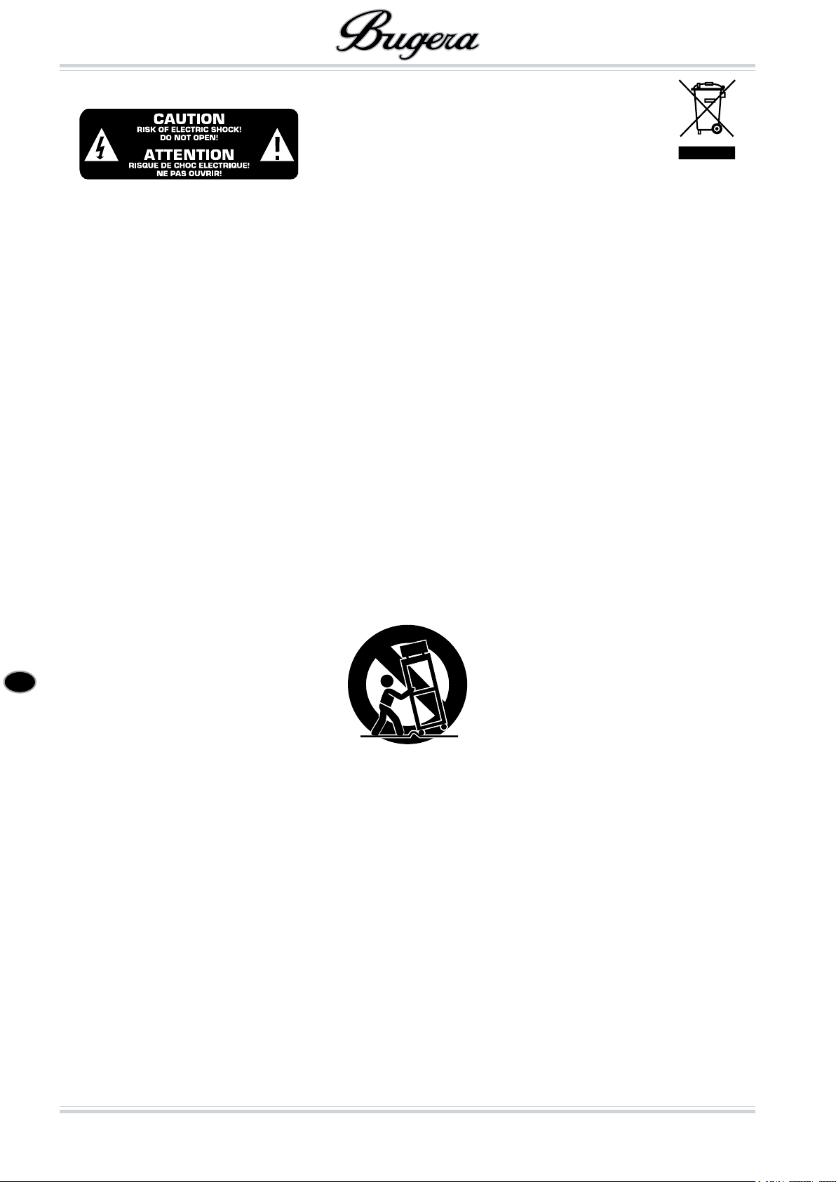
CAUTION: High voltage! Risk of death! High voltages of up to 500 V DC may be present inside the casing for long
periods after being disconnected from the mains. To avoid lethal electric shock, do not open the casing. There are no
user-serviceable components inside. Refer all maintenance to qualied service personnel. Remove the mains cable
when the unit is not in use.
WARNING: To eliminate the risk of re and electric shock, do not expose this unit to rain or moisture and splashing or
dripping liquid, which might enter the device. Do not place any objects lled with liquid, such as vases, on the unit.
This symbol, wherever it appears, alerts you to the presence of uninsulated dangerous voltage
inside the enclosure—voltage that may be sufcient to constitute a risk of shock.
*
This symbol, wherever it appears, alerts you to important operating and maintenance instruc-
tions in the accompanying literature. Please read the manual.
!
Read these instructions.1)
Keep these instructions.2)
Heed all warnings.3)
Follow all instructions.4)
Do not use this apparatus near water.5)
Clean only with dry cloth.6)
Do not block any ventilation openings. Install in accordance with the manufacturer’s instructions.7)
Do not install near any heat sources such as radiators, heat registers, stoves, or other apparatus 8)
(including ampliers) that produce heat.
Do not defeat the safety purpose of the polarized or grounding-type plug. A polarized plug has two 9)
blades with one wider than the other. A grounding type plug has two blades and a third grounding
prong. The wide blade or the third prong are provided for your safety. If the provided plug does not
t into your outlet, consult an electrician for replacement of the obsolete outlet.
Protect the power cord from being walked on or pinched particularly at plugs, convenience recep-10)
tacles, and the point where they exit from the apparatus.
Only use attachments/accessories specied by the manufacturer.11)
Use only with the cart, stand, tripod, bracket, or table specied by the manufacturer, or sold with the 12)
apparatus. When a cart is used, use caution when moving the cart/apparatus combination to avoid
injury from tip-over.
Unplug this apparatus during lightning storms or when unused for long periods of time.13)
Refer all servicing to qualied service personnel. Servicing is required when the apparatus has been 14)
damaged in any way, such as power supply cord or plug is damaged, liquid has been spilled or objects have fallen into the apparatus, the apparatus has been exposed to rain or moisture, does not
operate normally, or has been dropped.
The apparatus shall be connected to a MAINS socket outlet with a protective earthing connection.15)
Where the MAINS plug or an appliance coupler is used as the disconnect device, the disconnect de-16)
vice shall remain readily operable.
CAUTION - These service instructions are for use by qualied service personnel only. To reduce the 17)
risk of electric shock do not perform any servicing other than that contained in the operation instructions unless you are qualied to do so.
CAUTION! During use, the valves get very hot and high surface temperatures may be reached at the 18)
rear of this unit. To avoid burning yourself, make all connections while the unit is still cold.
Page 3
en
3
Table of contents
IMPORTANT NOTICE! ........................................................................ 4
Introduction ..................................................................................... 4
Before you get started .......................................................................................................4
Online registration .............................................................................................................4
Control elements .............................................................................. 5
Front panel .......................................................................................................................5
Rear panel ........................................................................................................................5
Footswitch ........................................................................................................................6
Inside the BUGERA ............................................................................................................7
INSTRUCTIONS FOR QUALIFIED SERVICE PERSONNEL ONLY ...................................................7
Wiring the BUGERA .......................................................................... 7
Audio connections ............................................................................ 8
Specications ................................................................................... 9
Limited warranty ............................................................................ 10
Page 4

en
Introduction
4
IMPORTANT NOTICE!
FAILURE TO OBSERVE THE FOLLOWING POINTS MAY RESULT IN DAMAGE TO THE AMPLIFIER OR LOUDSPEAKERS. DAMAGES CAUSED IN SUCH A WAY ARE NOT COVERED BY WARRANTY.
Before you start, always make sure that your
$
Bugera Valve Amplier is connected to a suitable loudspeaker. Observe the correct impedance for your loudspeaker and use the appropriate output socket.
Always use loudspeaker cables for connection
$
between the amplier and the loudspeaker.
Never use other types of cable, like instrument cable or microphone cable.
Switching the amplier on and off:
Before connecting the amplier to a power out-
$
let, make sure that both POWER and STANDBY
switches are set to the OFF position.
Power on (mandatory):
Switch the POWER switch on—wait for 60 sec-
$
onds—then switch the STANDBY switch on.
Power off (recommended):
Switch the STANDBY switch off—wait for 30
$
seconds—then switch the POWER switch off.
Note—after powering off we recommend that the ampli-
er is allowed to cool down for ten minutes before any
attempt is made to move the amplier. This reduces the
risk of mechanical damage to the sensitive valve elements.
ATTENTION! TO AVOID DAMAGE TO YOUR
AMP, NEVER USE THE BUGERA VALVE AM-
!
PLIFIER WITHOUT A LOUDSPEAKER CONNECTED!
Introduction
Congratulations! By purchasing the BUGERA 1990, you
get a classic 120-Watt valve amplier which stands out
for its raw power, reliability and mind-blowing “soul tone.”
The 2-channel preamplier design including BUGERA
ECC83/ECC83A preamp valves for breathtaking punch
and impressive gain. First-grade BUGERA 5881 power
valves, comprehensive sound control, 2 integrated reverb effects and an effect loop with volume control round
off the BUGERA 1990.
BUGERA instrument ampliers are handmade under
stringent production guidelines to ensure long life and
reliability. Each one includes our classic valve electronics,
hard-wearing switches and potentiometers, high-quality transformers and, not to forget, our hand-selected,
precision-matched BUGERA valves. And, owing to their
careful construction and component assembly, they are
able to stand up to the toughest demands.
Before you get started
Your product was carefully packed at the factory to en-
sure safe transport. Nevertheless, if the box is damaged
inspect the unit immediately for signs of damage.
If the unit is damaged please do NOT return it
$
to us, but notify your dealer and the shipping
company immediately; otherwise, claims for
damage or replacement may not be granted.
Always use the original box to prevent dam-
$
age during storage or transport.
Make sure that children cannot play unsuper-
$
vised with the unit or its packaging.
Please ensure proper disposal of all packing
$
materials.
Ensure adequate air supply and to avoid overheating do
not place the unit near radiators etc.
Please make sure that all devices are properly
$
grounded. For your own safety, never remove
or disable the ground conductors from the devices or on the power cords. The unit must always be connected to the mains outlet with a
protective grounding connection.
The tone quality may diminish within the
$
range of powerful radio broadcasting stations
and high-frequency sources. Increase the distance between the transmitter and the unit,
and use shielded cables for all connections.
Online registration
Please do remember to register your new BUGERA equipment right after your purchase by visiting www.bugeraamps.com and kindly read the terms and conditions of
our warranty carefully.
Should your BUGERA product malfunction, our goal is
to have it repaired as quickly as possible. To arrange for
warranty service, please contact the retailer from whom
the equipment was purchased. Should your BUGERA
dealer not be located in your vicinity, you may directly
contact the BEHRINGER company nearest to you. This
contact information is included in the original equipment
packaging (Global Contact Information/European Contact Information).
Registering your purchase and equipment with us helps
us process your repair claims quicker and more efciently.
Thank you for your cooperation!
ATTENTION!
We would like to draw your attention to the
$
fact that extremely loud sound levels may
damage your hearing as well as your loud-
speakers. Turn all VOLUME controls fully to
the left before you switch on the unit. Make
sure you select a suitable volume at all times.
Page 5
en
Control elements
5
Control elements
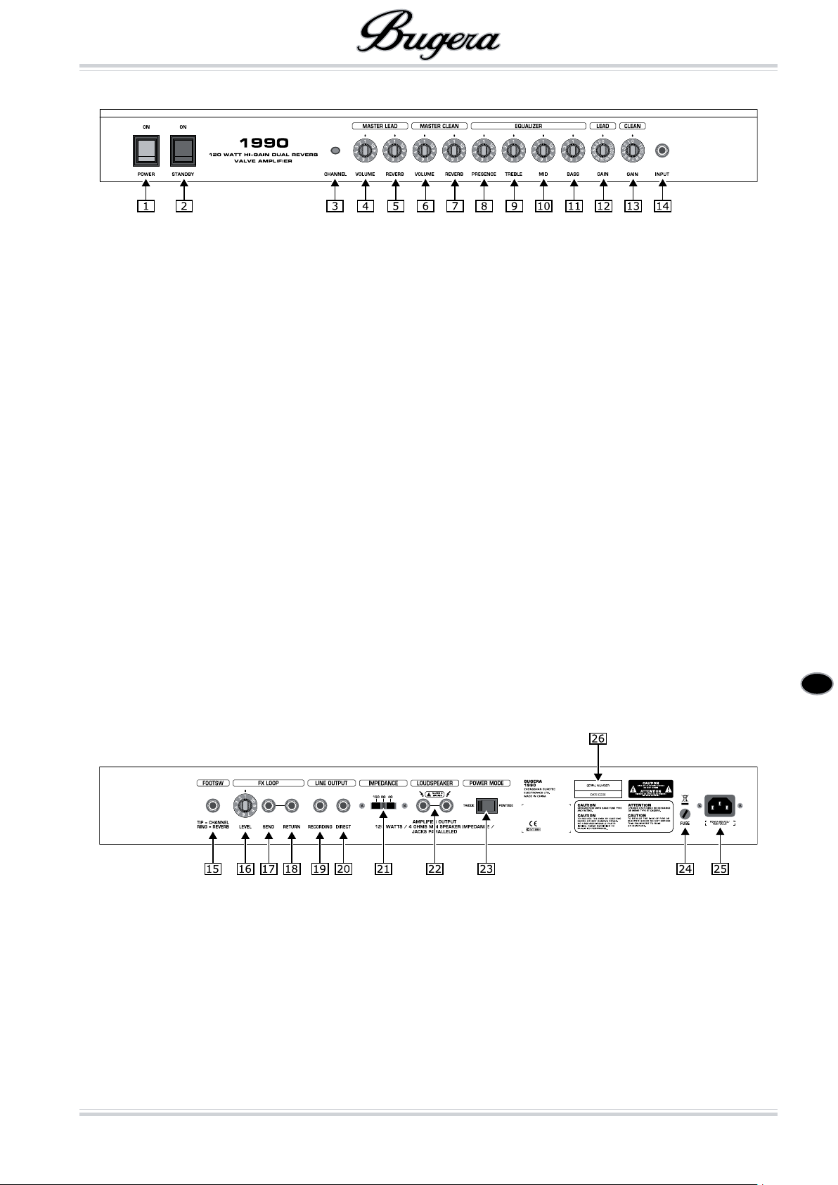
Front panel of the BUGERA 1990
Front panel
The 1 POWER switch is used to turn the power of the
BUGERA amplier on and off.
The 2 STANDBY switch allows you to place the amp
in STANDBY mode (OFF position). This way the
amp is idle, but the operational temperature of the
valves is maintained (POWER switch turned on).
When the switch is set to its ON position the ampli-
er is activated.
ATTENTION! TO AVOID DAMAGE TO YOUR
AMP, NEVER USE THE BUGERA VALVE AM-
!
PLIFIER WITHOUT A LOUDSPEAKER CONNECTED!
The 3 CHANNEL push button switches between the
CLEAN and the LEAD channel.
You can also activate both channels with the
$
supplied footswitch. Refer to “Footswitch” for
details.
This is the 4 VOLUME control that lets you adjust the
volume level of the LEAD channel.
This 5 REVERB rotary knob adjusts the effect level of
the built-in REVERB in the LEAD channel. The provided footswitch activates the REVERB effect (see
Chapter “Footswitch”).
This is the 6 VOLUME control that lets you adjust the
volume level of the CLEAN channel.
This 7 REVERB rotary knob adjusts the effect level of
the built-in REVERB in the CLEAN channel. The provided footswitch activates the REVERB effect (see
Chapter “Footswitch”).
The 8 PRESENCE rotary knob changes the tone of
the amplier in the upper frequencies. This emphasizes the high end and makes the sound crisper.
The passive 9 TREBLE control adjusts the upper fre-
quency range.
The passive 10 MID control adjusts the middle fre-
quency range.
The passive 11 BASS control adjusts the lower fre-
quency range.
This 12 GAIN control species the input level of the
LEAD channel. Turn the control to the right to in-
crease the preamplier’s distortion and sustain.
This 13 GAIN rotary knob adjusts the input level of the
CLEAN channel. Turning the knob to the right in-
creases the level of the preamplier and, therefore,
the signal’s strength.
The jack labeled 14 INPUT is the 1/4" input connector
on the BUGERA for hooking up your guitar. Use a
commercially available 1/4" mono cable.
Rear panel
CAUTION!
!
Hot! Risk of injury! During use, the valves
get very hot and high surface temperatures
may be reached at the rear of this unit.
Avoid touching the controls and connectors
on the rear panel during use. To avoid acci-
dental contact with hot surfaces, place the
rear panel so that it faces a wall.
Rear panel of the BUGERA 1960
The 15 FOOTSW(itch) jack is used to connect to the
provided footswitch. Please make sure that a cable
has been connected before turning on the amplier.
For more information, read Chapter “Footswitch.”
The 16 LEVEL rotary knob adjusts the output level of
the signal sent to an external effects unit or any
other signal processor (0 – 10). Turning the knob to
the right increases the signal level, whereas turning it to the left decreases the signal level. In order
to produce sound with the least possible noise, we
suggest using a high setting without distorting the
signal.
Page 6
en
Control elements
6
The 17 SEND output is used to connect a shielded ¼"
mono jack cable to the input of an external effects
unit.
The 18 RETURN input is used to connect a shielded
¼" mono jack cable to the output of an external
effects unit.
The 19 RECORDING output is used to connect directly
to a recording device or a PA system. This signal
is specially ltered to provide the optimum signal
quality for this application.
The 20 DIRECT output is used to route the amplier’s
unltered preamp signal, for example, to a second
amplier and loudspeaker system by retaining the
original sound.
The 21 IMPEDANCE switch lets you specify the loud-
speaker impedance. Always apply the value that
is identical to the impedance of the used speaker
cabinet. Please also read „Wiring the BUGERA“.
!
Both the paralleled 22 LOUDSPEAKER outputs (¼"
mono jacks) are used to connect the speaker
cabinet(s). The minimum impedance is 4 Ohms. The
IMPEDANCE switch should always be set to match
the impedance of the used speaker cabinet.
ATTENTION! TO AVOID DAMAGE TO YOUR
AMP, NEVER USE THE BUGERA VALVE AM-
!
PLIFIER WITHOUT A LOUDSPEAKER CONNECTED!
*
WARNING: ONLY REPLACE THE FUSE WHEN THE 24
MAINS CABLE HAS BEEN DISCONNECTED! The
FUSE is found in the fuse holder. If the fuse is
blown, it needs to be replaced with a fuse of the
same kind by all means. Otherwise, the unit could
seriously be damaged, in which case the warranty
is void. If the fuse is blown repeatedly, you should
take the unit to a qualied service technician.
*
The 25 IEC MAINS connector is used to connect the
mains cable that has the appropriate voltage ratings for your country (included). At all times, make
the connections to the amplier before plugging the
cable into a power outlet.
This is the 26 SERIAL NUMBER of the amplier.
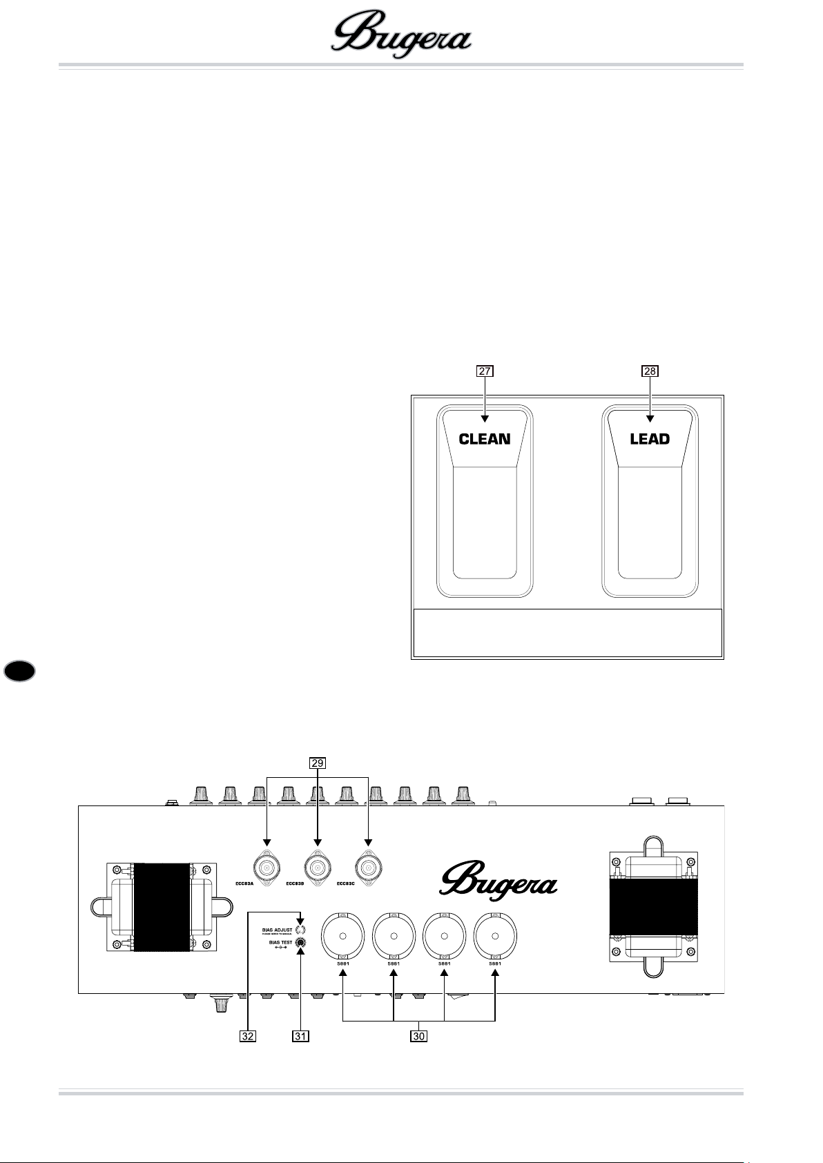
Footswitch
!
This 23 POWER MODE switch reduces the output
power of the amplier. In TRIODE mode, the amplier switches to 60 W operation, reducing the output
power by half (from 120 W to approx. 60 W). In
PENTODE mode, the amplier runs at full power in
pentode operation (120 W).
Footswitch
The 27 CLEAN switch activates the CLEAN channel.
The 28 LEAD switch activates the LEAD channel.
Inside the BUGERA 1990
Page 7
en
Wiring the BUGERA
7
Inside the BUGERA
DANGER!
High voltage! Risk of death!
*
High voltages of up to 500 V DC may be
present inside the casing for long periods
after being disconnected from the mains.
To avoid lethal electric shock, do not open
the casing. There are no user-serviceable
components inside. Refer all maintenance
to qualied service personnel. Remove the
mains cable when the unit is not in use.
The parts inside the amplier operate at
high voltages and high temperatures. To
*
avoid damage and injury that results from
re or electric shock, do not drop or spill
anything into the unit’s casing.
INSTRUCTIONS FOR QUALIFIED
SERVICE PERSONNEL ONLY
Remove the backside of the amplier’s casing to get to
the valves and the control elements.
These are the sockets for the 29 ECC83/ECC83A pre-
amp valves.
These are the sockets for the 30 5881 power amp
valves.
*
The 31 BIAS TEST connector lets you connect a volt-
meter in order to measure the power amp valves
(bias adjustment). Make sure that the voltmeter is
set to direct current (DC).
The 32 BIAS ADJUST control is used to make the bi-
as-adjustment.
Replacing the power amp valves also requires
$
bias adjustment. You should always use sets
of four matched valves. The valves of the
BUGERA Series are ideal for this purpose.
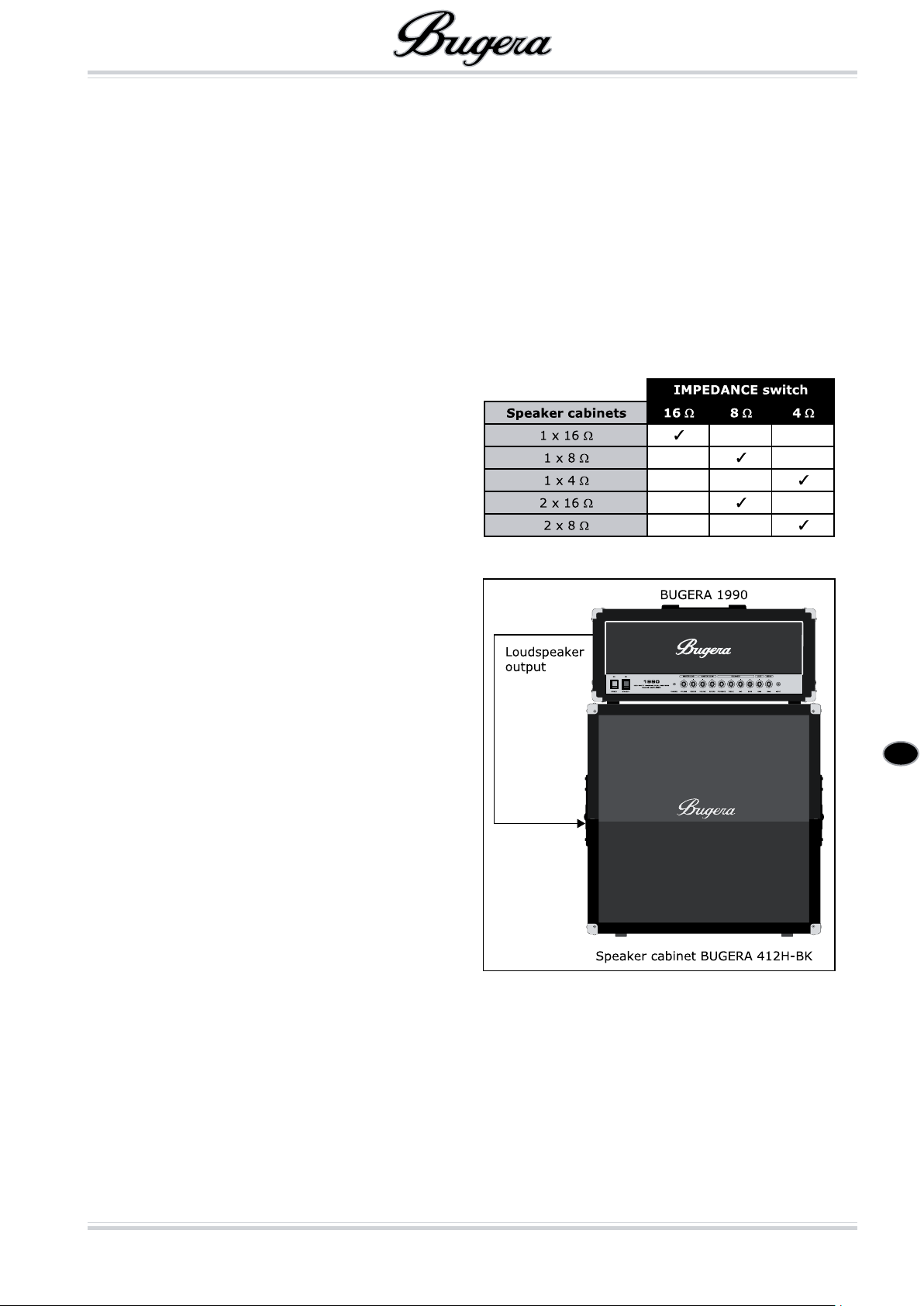
The BUGERA amplier has two paralleled LOUDSPEAKER
outputs which are used to connect one or two speaker
cabinets.
If you only connect one speaker cabinet, be sure that the
IMPEDANCE switch is set to match the impedance of the
connected cabinet.
If you want to connect two speaker cabinets, both cabinets should have to the same impedance. Be sure to
have set the IMPEDANCE switch correctly. In this case,
set it to half the value of one of the cabinets. When using
two 16-Ohm cabinets, the switch therefore needs to be
set to 8 Ohms; and with two 8-Ohm cabinets, set it to
the minimum impedance of 4 Ohms.
When you use two speaker boxes with differing impedance values, the speaker with the lower impedance will
provide the highest output power. In this case the IMPEDANCE switch must be set to half the value of the
speaker with the lower impedance value. Example: 16
ohms + 8 ohms -> 4 ohms.
Impedances
CAUTION: WE HIGHLY RECOMMEND THAT
BIAS ADJUSTMENTS BE CARRIED OUT BY
!
QUALIFIED PERSONNEL!
Wiring the BUGERA
CAUTION!
!
Hot! Risk of injury! During use, the valves
will get very hot and high surface temperatures may be reached at the rear of this
unit. To avoid burning yourself, make all
connections while the unit is still cold.
ATTENTION! TO AVOID DAMAGE TO YOUR
AMP, NEVER USE THE BUGERA VALVE AM-
!
PLIFIER WITHOUT A LOUDSPEAKER CONNECTED!
Connecting a speaker
Page 8
en
Audio connections
8
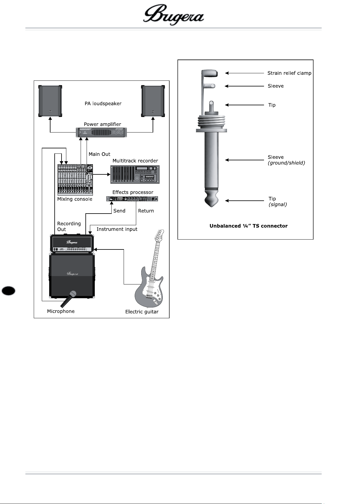
The following gure shows a setup with an external effects unit connected via the FX LOOP. What’s more, the
RECORDING output is connected to a mixer’s line chan-
nel to feed the signal to a recording device. The speaker
signal of the connected loudspeaker is picked up by a
microphone and is fed to the mixer via a mic input. This
way you get a second guitar signal that is amplied over
a PA system or can be recorded additionally or both.
Audio connections
The inputs and outputs of the BUGERA amplier use
mono jack connectors.
¼" mono jack connector
Set-up for live playing
Page 9
en
Specications
9
Specications
PREAMP SECTION
Valves
Type 2 x ECC83A
1 x ECC83
Instrument Input
Impedance 1 MΩ
Clean Channel
Nominal input level –10 dBV
Minimum input level –50 dBV
Maximum input level 0 dBV
Lead Channel
Nominal input level –80 dBV
Minimum input level –92 dBV
Effects Send
Impedance 15 kΩ
Nominal output level –12 to 0 dBV
Effects Return
Impedance 15 kΩ
Minimum input sensitivity –12 to 0 dBV
Recording Output
Impedance 47 kΩ
Nominal output level +0 dBV
Direct Output
Impedance 10 kΩ
Nominal output level +3 dBV
POWER AMPLIFIER SECTION
Valves
Type 4 x 5881
Output Power
Peak power 60 W/120 W switchable / 16, 8, 4 Ω
Loudspeaker Connectors
Type ¼" TS connectors, unbalanced
Load impedance 4 Ω / 8 Ω / 16 Ω switchable
POWER SUPPLY
Power Consumption Maximum 350 W
Mains Voltage / Fuse
100 – 120 V~, 50/60 Hz T 3.15 A H 250 V
220 – 230 V~, 50/60 Hz T 1.6 A H 250 V
Mains Connector Standard IEC receptacle
DIMENSIONS/WEIGHT
Dimensions (H x W x D) 12.2 in / 310 mm x 27.2 in / 690 mm x 9.6 in / 245 mm
Weight 49.6 lb / 22.5 kg
We are constantly striving to maintain the highest professional standards. As a result of these efforts, modications may be made from time to time to
existing products without prior notice. Specications and appearance may differ from those listed or illustrated.
Page 10

en
Limited warranty
10
Limited warranty
SPECIAL NOTE: NO USER SERVICEABLE PARTS INSIDE. REFER SERVICING TO QUALIFIED PERSONNEL ONLY.
Other warranty rights and national law § 1
This limited warranty does not exclude or limit the buyer’s statutory rights provided by national law, in particular, any such rights against the seller that 1.
arise from a legally effective purchase contract.
The limited warranty regulations mentioned herein are applicable unless they constitute an infringement of national warranty law.2.
Online registration§ 2
Please do remember to register your new BUGERA equipment right after your purchase by visiting http://www.bugera-amps.com and kindly read the terms
and conditions of our limited warranty carefully. Registering your purchase and equipment with us helps us process your repair claims quicker and more
efciently. Thank you for your cooperation!
Limited Warranty§ 3
BEHRINGER warrants the mechanical and electronic components of this product to be free of defects in material and workmanship if used under normal 1.
operating conditions for a period of one (1) year** from the original date of purchase.
BEHRINGER warrants valves (tubes) and meters contained in the product to be free of defects in material and workmanship if used under normal operat-2.
ing conditions for a period of 90 days from the original date of purchase.
This limited warranty is subject to the conditions, exclusions and limitations hereinafter set forth.3.
If the product shows any defects within the specied warranty period that are not excluded from this warranty as described under § 5, BEHRINGER will, 4.
at its discretion, either replace the product by providing a new or reconditioned product or repair the product using suitable new or reconditioned parts.
In the case that other parts are used which constitute an improvement, BEHRINGER may, at its discretion, charge the customer for the additional cost
of these parts. In case BEHRINGER decides to replace the entire product, this warranty shall apply to the replacement product for the remaining initial
warranty period, i.e., one year** from the date of purchase of the initial product.
If the warranty claim proves to be justied, the product will be returned to the user freight prepaid.5.
Warranty claims other than those indicated above are expressly excluded.6.
PLEASE RETAIN YOUR SALES RECEIPT, AS IT IS YOUR PROOF OF PURCHASE COVERING YOUR LIMITED WARRANTY. THIS LIMITED WARRANTY IS VOID
WITHOUT SUCH PROOF OF PURCHASE.
Return authorization number§ 4
To obtain warranty service, the buyer (or his authorized dealer) must call BEHRINGER as exclusive distributor of BUGERA products (see enclosed list) 1.
during normal business hours BEFORE returning the product. All inquiries must be accompanied by a description of the problem. The buyer or his authorized dealer will receive a return authorization number
Subsequently, the product must be returned in its original shipping carton, together with the return authorization number. The return shipment address 2.
will be indicated by BEHRINGER.
Shipments without freight prepaid will not be accepted.3.
Warranty regulations§ 5
Warranty services will be furnished only if the product is accompanied by a copy of the original retail dealer’s invoice.1.
If the product needs to be modied or adapted in order to comply with applicable technical or safety standards on a national or local level, in any country 2.
which is not the country for which the product was originally developed and manufactured, this modication/adaptation shall not be considered a defect
in materials or workmanship. This limited warranty does not cover any such modication/adaptation, irrespective of whether it was carried out properly
or not. Under the terms of this limited warranty, BEHRINGER shall not be held responsible for any cost resulting from such a modication/adaptation.
Free inspections and maintenance/repair work are expressly excluded from this limited warranty, in particular, if caused by improper handling of the 3.
product by the user. This also applies to defects caused by normal wear and tear, in particular, of faders, crossfaders, potentiometers, keys/buttons,
tubes, guitar strings, illuminants and similar parts.
Damage/defects caused by the following conditions are not covered by this limited warranty:4.
improper handling, neglect or failure to operate the unit in compliance with the instructions given in BEHRINGER user or service manuals >
connection or operation of the unit in any way that does not comply with the technical or safety regulations applicable in the country where the >
product is used.
damage/defects caused by force majeure or any other condition that is beyond the control of BEHRINGER. >
Any repair or service performed by any person or entity other than a BEHRINGER authorized service center is not covered by this limited warranty.5.
Any repair or opening of the unit carried out by unauthorized personnel (user included) will void this limited warranty.6.
Any exchange of the tubes/valves and associated biasing by any person or entity other than a BEHRINGER authorized service centre will void this limited 7.
warranty.
If an inspection of the product by BEHRINGER shows that the defect in question is not covered by this limited warranty, the inspection costs are payable 8.
by the customer.
Products which do not meet the terms of this limited warranty will be repaired exclusively at the buyer’s expense. BEHRINGER will inform the buyer of 9.
any such circumstance. If the buyer fails to submit a written repair order within 6 weeks after notication, BEHRINGER will return the unit. Costs for
freight and packing will be invoiced separately C.O.D. When the buyer has sent in a written repair order, such costs will also be invoiced separately.
Warranty transferability§ 6
This limited warranty is extended exclusively to the original buyer (customer of retail dealer) and is not transferable to anyone who may subsequently
purchase this product.
Claim for damages§ 7
Failure of BEHRINGER to provide proper warranty service shall not entitle the buyer to claim (consequential) damages. In no event shall the liability of
BEHRINGER exceed the invoiced value of the product.
U.S. Customers only§ 8
THE FOREGOING CONSTITUTES THE ONLY WARRANTY MADE BY BEHRINGER WITH RESPECT TO THE PRODUCT AND IS MADE EXPRESSLY IN LIEU OF ALL
OTHER WARRANTIES EXPRESS OR IMPLIED. Any implied warranties, including without limitation, any implied warranties of merchantability or tness for
any particular purpose, imposed under state law are limited to the duration of this limited warranty. Some states do not allow limitations on how long an
implied warranty lasts, so the above limitations may not be applicable to you.
BEHRINGER ASSUMES NO LIABILITY FOR PROPERTY DAMAGE RESULTING FROM FAILURE OF THIS PRODUCT NOR ANY LOSS OF INCOME, SATISFACTION
OR DAMAGES ARISING FROM THE LOSS OF USE OF SAME DUE TO DEFECTS OR AVAILABILITY OF SAME DURING SERVICE.
**Customers in the European Union please contact BEHRINGER Germany Support for further details.
Technical specications and appearance are subject to change without notice. The information contained herein is correct at the time of printing. RED
CHIP COMPANY LTD accepts no liability for any loss which may be suffered by any person who relies either wholly or in part upon any description, pho-
tograph or statement contained herein. Colors and specications may vary slightly from product. Our Products are sold through authorized dealers only.
This manual is copyrighted. No part of this manual may be reproduced or transmitted in any form or by any means, electronic or mechanical, includ-
ing photocopying and recording of any kind, for any purpose, without the express written permission of RED CHIP COMPANY LTD. BUGERA-products
are distributed exclusively by the BEHRINGER Group of companies globally, and specically by BEHRINGER Luxembourg Sàrl in the European Union.
ALL RIGHTS RESERVED. © 2009 RED CHIP COMPANY LTD. Trident Chambers, Wickhams Cay, P.O. Box 146, Road Town, Tortola, British Virgin Islands.
 Loading...