

Page 1

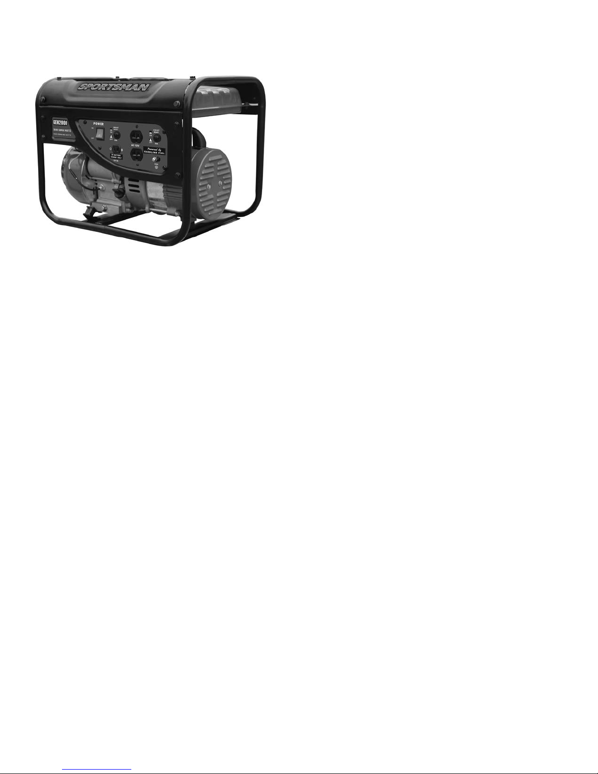
GEN2000
2000 Surge Watts / 1400 Running Watts
PORTABLE GASOLINE GENERATOR INSTRUCTION MANUAL
READ ALL INSTRUCTIONS AND WARNINGS BEFORE USING THIS PRODUCT.
This manual provides important information on proper operation & maintenance. Every effort has been
made to ensure the accuracy of this manual. These instructions are not meant to cover every possible
condition and situation that may occur. We reserve the right to change this product at any time without
prior notice.
IF THERE IS ANY QUESTION ABOUT A CONDITION BEING SAFE OR UNSAFE,
DO NOT OPERATE THIS PRODUCT!
DO NOT RETURN THIS GENERATOR TO THE RETAILER!
If you experience a problem, have questions or need parts for this product, call Customer Service at
1-866-460-9436, Monday-Friday, 8 AM - 4 PM Central Time. A copy of the sales receipt is required.
FOR CONSUMER USE ONLY – NOT FOR PROFESSIONAL USE.
KEEP THIS MANUAL, SALES RECEIPT & APPLICABLE WARRANTY FOR FUTURE
REFERENCE.
Visit our website for Troubleshooting / Frequently Asked Questions
http://sportsmanseriesbrand.com/generators
Page 2
GEN2000 Portable Gasoline Generator
2
GEN2000 Portable Gasoline Generator
FEATURES:
• 2000 Surge Watts / 1400 Running Watts
• 4-Stroke OHV Engine 94cc
• Recoil Start
• 3.5 HP Gasoline Engine
• 2 - 120 Volt A/C Outlet
• 1 - 12 Volt D/C Outlet
• Engine Run Time: 9 Hours @ 50% Load
• Low Oil Shutdown
• EPA Approved
• Noise Level: < 68dB @ 0% Load
• Oil Capacity: 12 ounces
• Fuel Capacity: 1.2 gallon
• Fuel Type: Unleaded Gasoline Only 87 rating or higher
• 3,600 RPM
• Mobility Kit Not Available
• If you are using a generator above sea level, the generator may not function properly because of air flow getting through the mixer.
Page 3

GEN2000 Portable Gasoline Generator
3
TABLE OF CONTENTS
RECOGNIZE SAFETY SYMBOLS, WORDS AND LABELS .............................................................................................. 4
PACKAGE CONTENTS
PACKAGE CONTENTS .......................................................................................................................................... 9
COMPONENTS ..................................................................................................................................................... 10
PREPARING THE GENERATOR FOR USE ................................................................................................................... 11
Using This Generator For The First Time .............................................................................................................. 11
Step 1 – Add Oil ............................................................................................................................................ 11
Step 2 – Add Gasoline .................................................................................................................................. 12
Step 3 – Ground The Generator ................................................................................................................... 12
Subsequent Use Of This Generator ...................................................................................................................... 13
Step 1 – Verify Oil Level ............................................................................................................................... 13
Step 2 – Verify Gas Level ............................................................................................................................. 13
Step 3 – Ground The Generator ................................................................................................................... 13
STARTING THE GENERATOR ....................................................................................................................................... 14
USING THE GENERATOR .............................................................................................................................................. 15
AC Usage .............................................................................................................................................................. 15
DC Usage .............................................................................................................................................................. 16
STOPPING THE GENERATOR ....................................................................................................................................... 17
MAINTENANCE/CARE .................................................................................................................................................... 17
Recommended Maintenance Schedule ................................................................................................................ 17
Cleaning The Generator ........................................................................................................................................ 17
Checking The Oil Level ......................................................................................................................................... 17
Changing/Adding Oil ............................................................................................................................................. 18
Air Filter Maintenance ........................................................................................................................................... 19
Spark Plug Maintenance ....................................................................................................................................... 19
Emptying The Fuel Tank ....................................................................................................................................... 19
STORAGE/TRANSPORT PROCEDURES ...................................................................................................................... 20
TROUBLESHOOTING ..................................................................................................................................................... 20
PARTS DIAGRAM ............................................................................................................................................................ 22
EMISSION CONTROL SYSTEM WARRANTY ................................................................................................................ 28
Page 4

GEN2000 Portable Gasoline Generator
4
RECOGNIZE SAFETY SYMBOLS, WORDS AND LABELS
What You Need to Know About Safety Instructions
Warning and Important Safety Instructions appearing in this manual are not meant to cover all possible conditions and situations that
may occur. Common sense, caution and care must be exercised when operating or cleaning tools and equipment.
Always contact your dealer, distributor, service agent or manufacturer about problems or conditions you do not understand.
This is the safety alert symbol. It is used to alert you to potential
personal injury hazards. Obey all safety messages that follow this
symbol to avoid possible injury or death.
DANGER indicates an imminently hazardous situation
which, if not avoided, will result in death or serious injury.
WARNING indicates a potentially hazardous situation which,
if not avoided, could result in death or serious injury.
CAUTION indicates a potentially hazardous situation which,
if not avoided, may result in minor or moderate injury.
CAUTION used without the safety alert symbol indicates a
potentially hazardous situation which, if not avoided, may
result in property damage.
2 YEAR LIMITED EMISSION-RELATED WARRANTY
THIS ENGINE MEETS U.S. EPA EMISSION STANDARDS UNDER 40 CFR 1054.625 .The emission-related limited warranty is valid for two (2)
years. Keep the purchase receipt and mail in the product registration card for proof of purchase. Buffalo Corp limits emission-related warranty repairs
to authorized service centers for owners located within 100 miles of an authorized service center. For owners located more than 100 miles from an
authorized service center, Buffalo Corp will, in its sole discretion, either pay for shipping costs to and from an authorized service center, provide for a
service technician to come to the owner to make the warranty repair, or pay for the repair to be made at a local non-authorized service center. The
provisions of this paragraph apply only for the contiguous states, excluding the states with high-altitude areas identified in 40 CFR part 1068,
Appendix III.
To exercise this warranty, DO NOT RETURN TO RETAILER. Instead, call Customer Service toll free at 1-866-460-9436 (email address
info@buffalotools.com) and you will be instructed on where to take the engine for warranty service. Take the generator and proof of purchase (your
receipt) to the repair facility recommended by the Customer Service Representative. The warranty does not extend to generators damaged or
affected by fuel contamination, accidents, neglect, misuse, unauthorized alterations, use in an application for which the product was not designed
and any other modifications or abuse.
1 YEAR LIMITED WARRANTY (30 Day Limited Warranty for Commercial and Rental Purpose)
Generators are warranted to be free from defects in materials and workmanship for a period of 1 YEAR from date of original purchase. Buffalo Corp.
is not liable for any indirect, incidental or consequential damages from the sale or use of this product. Any implied warranties are limited to 1 YEAR
as stated, or as otherwise stated, in this written limited warranty. Some states do not allow the exclusion or limitation of incidental or consequential
damages. Some states do not allow limitation on the length of an implied warranty. Buffalo Corp will repair or replace, at its discretion, any part that
is proven to be defective in materials or workmanship under normal use during the 1 YEAR warranty period. Warranty repairs or replacements will be
made without charge for parts or labor. Parts replaced during warranty repairs will be considered as part of the original product and will have the
same warranty period as the original product. This warranty gives you specific legal rights, and you may have other rights that vary state to state.
Page 5
GEN2000 Portable Gasoline Generator
5
Notice Regarding Emissions:
Engines certified to comply with U.S. EPA emission regulations for SORE (Small Off Road Equipment) are certified to operate on regular unleaded
gasoline and may include the following emission control systems: Three-Way Catalyst (TWC) (if equipped), and Engine Modifications (EM).
Legal Requirements:
Federal and/or State Occupational Safety and Health Administration (OSHA) regulations, local codes, and/or ordinances may apply to the intended
use of this generator. Consult a qualified electrician, electrical inspector, and/or the local agency having jurisdiction. Some areas require generators
to be registered with local utility companies. Additional regulations may apply if this generator will be used at a construction site.
IMPORTANT SAFETY INSTRUCTIONS
STOP!
Before using this generator and if you have any questions regarding the hazard and safety notices listed in this manual and/or on this
generator, call 1-866-460-9436, Monday - Friday, 8 AM - 4 PM Central Time.
WARNING: Do not connect this generator to a home or office electrical system. Connecting a generator to your electric utility
company’s power lines or to another power source could damage your generator and your appliances and could cause serious injury or
even death to you or a utility worker who may be working on nearby power lines. Plug your appliances directly into the generator, do not
plug the generator into any electric outlet in your home. Doing so could create a connection to the utility company power lines. You are
responsible for ensuring that your generator’s electricity does not feed back into the electric utility power lines.
WARNING: Do not use this generator to provide power for emergency medical equipment or life support devices.
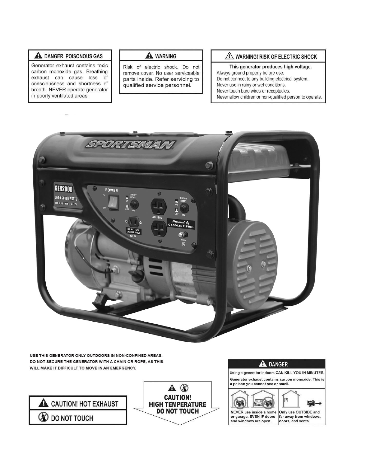
Carbon Monoxide Gas: When in operation, the exhaust from this generator contains poisonous carbon monoxide gas. Carbon monoxide
gas is both odorless and colorless AND may be present even if you do not see or smell gas. Breathing this poison gas can lead to
headaches, dizziness, drowsiness, loss of consciousness and eventually death.
WARNING: USE THIS GENERATOR ONLY OUTDOORS IN NON-CONFINED AREAS. DO NOT SECURE THE GENERATOR WITH A CHAIN
OR ROPE, AS THIS WILL MAKE IT DIFFICULT TO MOVE IN AN EMERGENCY.
• Keep at least several feet of clearance on all sides to allow proper ventilation for this generator.
Chemicals: According to the State of California, the exhaust from this generator contains chemicals known to cause cancer, birth
defects, or other reproductive harm.
Chemicals: This product contains or emits chemicals known to the State of California to cause cancer, birth defects and other
reproductive harm.
Usage: This generator is not intended to power sensitive electronic equipment such as TVs, DVD players, stereos, desktop computers or
laptop computers without the use of an appropriate line conditioner and/or surge protector (both not included). Sensitive electronic
equipment should be operated on approved inverter type generators or pure sine wave generators. For additional information consult the devices
operation manual or call customer service at 1-866-460-9436 Monday - Friday, 8 AM - 4 PM Central Time.
Usage: Avoid the use of extension cords if possible. If you choose to use them, be sure they are sized adequately to handle the flow of
electricity. An undersized cord can overheat, short out and cause a fire.
Page 6
GEN2000 Portable Gasoline Generator
6
Powerful Voltage: This generator produces powerful voltage, which can result in electrocution.
• ALWAYS ground this generator before using it. (See “Ground the Generator” section in this manual).
• Only electrical devices should be plugged into this generator, either directly or with an extension cord. NEVER connect a building electrical
system to this generator without a qualified electrician. Doing so voids your warranty. Such connections must isolate generator power from utility
power and comply with local electrical laws and codes. Failure to comply can create a back feed into utility lines creating an electrocution hazard,
which may result in serious injury or death to utility workers. Such a back feed may cause this generator to explode, burn and create fires when
utility power is restored.
• Use a ground fault circuit interrupter (GFCI) in highly conductive areas such as metal decking or steel work. GFCIs are available in-line with some
extension cords.
• Keep generator dry and operate with dry hands. Do not use this generator in wet conditions (rain, snow, active sprinkler system, wet hands, etc.).
• Do not touch bare wires or outlets (receptacles).
• Do not allow children or non-qualified persons to operate this generator.
Flammable Gasoline: This generator may emit highly flammable and explosive gasoline vapors, which can cause severe burns or even
death. A nearby open flame can lead to an explosion even if not directly in contact with gasoline.
• Do not operate this generator near open flame.
• Do not smoke near this generator.
• Always operate this generator on a firm, level surface.
Gasoline is highly flammable and explosive. Handling fuel can result in serious injury or burns.
• Always shut down this generator before refueling. Refuel in a well-ventilated area. Keep heat, sparks and flame away while refueling and away
from the location where gasoline is stored. Never refuel indoors where gasoline fumes may reach flames and/or sparks.
• Allow this generator to cool for at least 2 minutes before removing the fuel tank cap. Loosen the cap slowly to relieve pressure in the fuel tank.
Avoid spilling fuel.
• Do not fill the fuel tank above the upper limit line. Gasoline may expand during operation. Do not fill to the top of the tank.
• Always check for spilled gasoline and immediately wipe it up before starting this generator.
• Empty the fuel tank before storing or transporting this generator.
• Always handle fuel outdoors.
• Before transporting, turn the fuel valve to the “OFF” position and disconnect the spark plug.
High Temperatures: This generator produces heat when in operation. Temperatures near the exhaust can exceed 150 Degrees
Fahrenheit (65 Degrees Celsius).
• Do not touch hot surfaces. Observe all warning placards on this generator denoting hot surfaces.
• Allow this generator to cool for several minutes after use before touching the engine, muffler or other areas that are hot during operation and
before storing indoors.
• Hot exhaust may ignite some materials. Keep flammable materials away from this generator.
• Keep at least several feet of clearance on all sides of this generator during operation. Do not enclose this generator in any structure.
Usage: Misuse of this generator can damage it or shorten its life. Use this generator only for its intended purpose.
• Operate this generator only on a dry, level surface. Do not secure the generator with a chain or rope, which would prevent it from being moved in
an emergency.
• Allow this generator to run for several minutes before connecting any electrical devices.
• Promptly turn off any malfunctioning devices and disconnect them.
• Do not operate an excessive number of electrical devices in excess of the wattage capacity of this generator.
• Do not turn on electrical devices until after they are connected to this generator.
• Turn off all connected electrical devices before stopping this generator.
Usage: Consult a physician(s) before using this generator if using a pacemaker. Electromagnetic fields in close proximity to a heart
pacemaker could cause a pacemaker to malfunction or fail. Caution is necessary when near the engine’s recoil starter.
Usage: Prolonged exposure to high noise levels can be hazardous to hearing. Always wear ANSI-approved hearing protection when
operating or working around the generator when it is running.
Page 7
GEN2000 Portable Gasoline Generator
7
Page 8
GEN2000 Portable Gasoline Generator
8
In addition to the previously described safety information, familiarize yourself with all safety and hazard placards on this generator.
Page 9
GEN2000 Portable Gasoline Generator
9
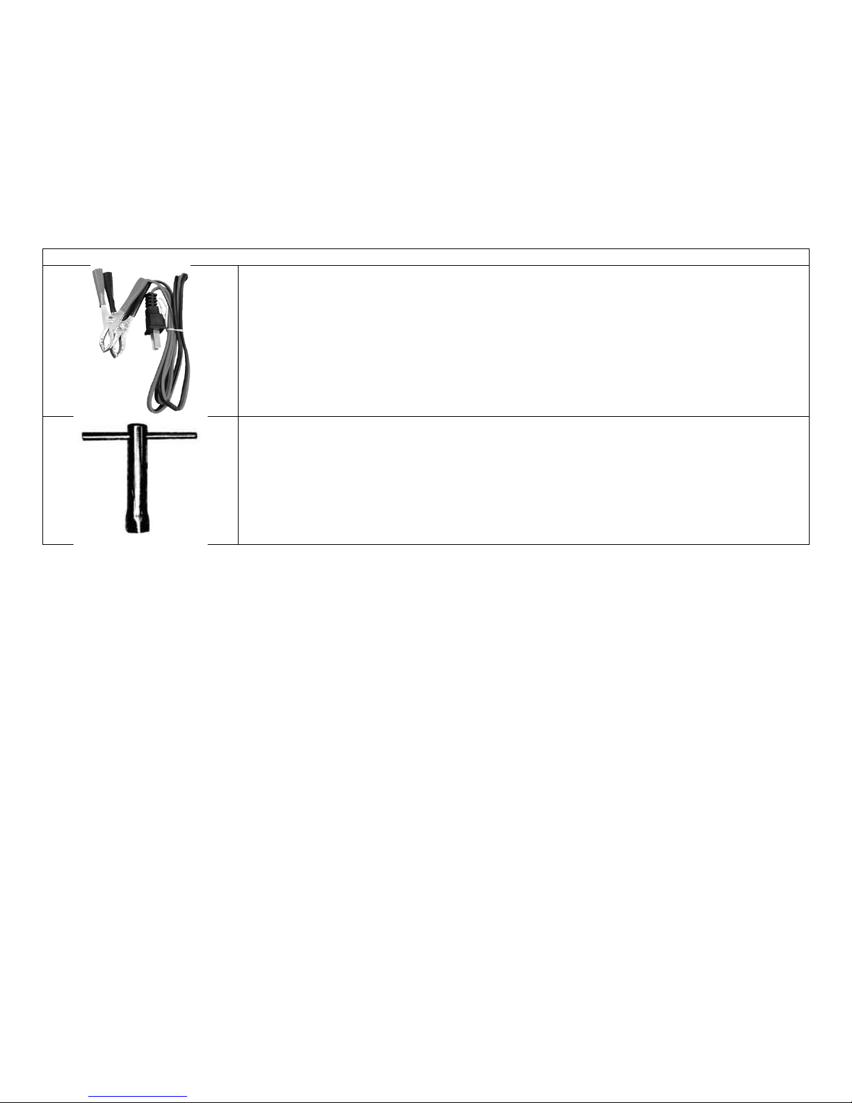
PACKAGE CONTENTS
The following items are supplied with this Generator. Verify that all items are included.
STOP!
If there are missing items, call 1-866-460-9436, Monday - Friday, 8 AM - 4 PM Central Time for customer service. DO NOT RETURN THIS
GENERATOR TO THE RETAILER.
Item List:
DC connector wires for charging 12 Volt automotive-type batteries
Spark plug wrench
Page 10
GEN2000 Portable Gasoline Generator
10
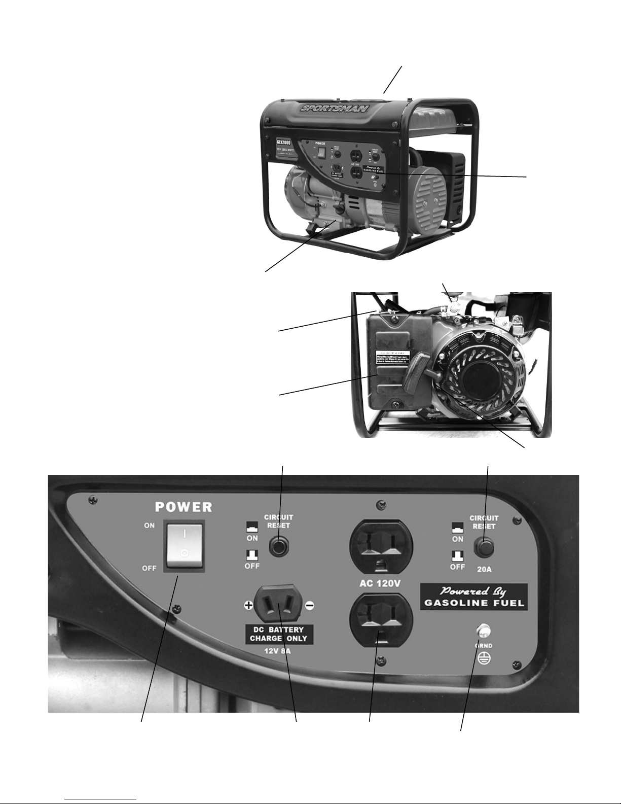
8) AC Circuit Protector
9) Engine Switch
10) 120 Volt AC Outlet
11) DC Circuit Protector
12) 12 Volt DC Outlet
13) Grounding Terminal
1) Fuel Tank Cap
2) Control Panel
3) Oil Access
4) Fuel Cock
5) Carburetor Choke Lever
6) Air Filter Cover
7) Recoil Starter
GENERATOR COMPONENTS
Observe the locations and functions of the various components and controls of this generator.
9
1 2 8
10
13
12
3
7
4 6 5
11
Page 11

GEN2000 Portable Gasoline Generator
11
PREPARING THE GENERATOR FOR USE
Using this Generator for the First-Time
STOP!
The following section describes the required steps for preparing this generator for the first use. Failure to correctly perform these steps
can damage this generator and/or shorten its life. If still unsure about how to perform any of these steps after reading this section, call
1-866-460-9436 Monday - Friday, 8 AM - 4 PM Central Time for customer service.
If this generator is being used for the first time, the following few steps are required to prepare it for operation:
Step 1 - Add Oil
THIS GENERATOR REQUIRES AT LEAST 12.0 OUNCES OF OIL (SAE10W-30) TO RUN.
ADD OIL UNTIL IT IS ALMOST OVERFLOWING. THE LOW-OIL SENSOR IS VERY SENSITIVE AND THE ENGINE
WILL NOT RUN IF THE OIL IS LOW. START WITH 12.0 OUNCES, THEN ADD MORE UNTIL ALMOST OVERFLOWING.
TROUBLESHOOTING: IF THE GENERATOR WILL NOT START, DOUBLE CHECK THAT THE OIL LEVEL IS
COMPLETELY FULL AND ALMOST OVERFLOWING.
This generator requires engine oil to function. Engine oil is a major factor affecting engine performance and service life. When new from
the package, this generator contains no oil in the engine crankcase. Add oil before operating this generator for the first time. When replenishing oil
for subsequent use of this generator, always determine that this generator has the correct quantity of oil.
To add oil to the engine crankcase:
1. Confirm that this generator is on a level surface.
2. Unscrew the oil filler/dipstick cap from the engine as illustrated in Figure 1 below.
3. Using a funnel, add high detergent motor oil to fill the engine crankcase to the correct quantity. SAE10W-30 oil is recommended for general use.
When the engine crankcase is full and almost overflowing, the oil level should reach the lower lip of the oil filling opening as shown in Figure 2.
4. Replace the oil filler/dipstick cap and close the oil access panel.
Figure 1 – Unscrew the Dipstick Cap
Figure 2 - Add Oil
Page 12

GEN2000 Portable Gasoline Generator
12
Step 2 - Add Gasoline
Gasoline and gasoline fumes are highly flammable and explosive. Handling fuel can result in serious injury or burns.
• Do not fill the fuel tank near a heat, sparks or an open flame. Keep gasoline away from appliance pilot lights, barbecues, electric appliances, power
tools, etc.
• Do not overfill the fuel tank. Always check for fuel spills and immediately wipe them up. Spilled fuel is a fire hazard and causes environmental
damage.
To add gasoline:
To ensure that this generator runs smoothly, use only FRESH, UNLEADED GASOLINE WITH AN OCTANE RATING OF 87 OR HIGHER. Unleaded
gasoline produces fewer engine and spark plug deposits and extends the life of the exhaust system.
1. Confirm that this generator is on a level surface.
2. Unscrew fuel tank cap and set aside. (NOTE: The fuel tank cap may be tight and difficult to unscrew.)
3. Slowly add fresh, unleaded gasoline (with an octane rating 87 or higher) to the fuel tank. Be careful not to fill the fuel tank above the upper limit
line. NOTE: Because gasoline can expand, do not fill the fuel tank to the very top.
4. Securely tighten the fuel tank cap and immediately wipe up any spilled gasoline with a dry cloth.
Fuel Tank Capacity (gallons)
1.2
Fuel Type
Fresh, Unleaded Gasoline Octane Rating 87 or Higher
IMPORTANT:
• Use only UNLEADED gasoline with an octane rating of 87 or higher.
• Never use a mixture of oil and gasoline.
• Never use old and/or contaminated gasoline.
• Avoid getting dirt and/or water in the fuel tank.
• Gasoline can age in the fuel tank and make it difficult to start this generator. Never store this generator for extended time with gasoline in the
fuel tank.
Step 3 - Ground the Generator
Failure to properly ground this generator can result in electrocution.
Ground this generator by tightening the grounding nut against a grounding wire as illustrated in Figure 3. A No. 12 AWG (American Wire Gauge)
stranded copper wire is generally an acceptable grounding wire. The other end of this grounding wire should be connected to a copper or brass
grounding rod that is driven into the earth.
Grounding codes can vary by location. Contact a local electrician for information on grounding regulations for your area.
Figure 3
The Grounding Terminal
is located on the front of
the generator, to the
right of the DC Output
socket.
Page 13

GEN2000 Portable Gasoline Generator
13
Subsequent Use of this Generator
For subsequent uses of this generator after the first use, certain steps still must be completed to prepare it for operation.
IMPORTANT: Be familiar with the procedures described in the previous section titled “Using the Generator for the First Time” of this
manual. If not, review this section now.
Step 1 - Verify Oil Level
It is important to check the oil level in the engine crankcase before each use to ensure that there is sufficient quantity.
1. Verify that this generator is on a level surface.
2. Unscrew the oil filler/dipstick cap from the engine.
3. With a dry cloth, wipe the oil off of the dipstick that is located on the inside of the cap.
4. Fully insert the dipstick without screwing the filler/dipstick cap and then remove again. There should be oil on the dipstick. If there is no oil on the
dipstick, or oil is visible only at the very end of the dipstick, add oil until the engine crankcase is filled. (See “Changing/Adding Oil” in the
“Maintenance/Care” section of this manual).
5. Confirm that the oil filler/dipstick cap is properly screwed in place when finished verifying the oil level.
Step 2 - Verify Gas Level
Before starting this generator, verify that there is sufficient gasoline in the fuel tank. If necessary, add fresh unleaded gasoline with an octane rating
of 87 or higher according to “Step 2 - Add Gasoline” of the “Using this Generator for the First Time” section of this manual.
Fuel Tank Capacity (gallons)
1.2
Fuel Type
Fresh, Unleaded Gasoline Octane Rating 87 or Higher
Gasoline and gasoline fumes are highly flammable and explosive. Handling fuel can result in serious injury or burns.
• Do not fill the fuel tank near a heat, sparks or an open flame. Keep gasoline away from appliance pilot lights, barbecues, electric appliances, power
tools, etc.
• Always allow several minutes for the engine to cool before refueling.
• Do not overfill the fuel tank. Always check for fuel spills and immediately wipe them up. Spilled fuel is a fire hazard and causes environmental
damage.
IMPORTANT:
• Use only fresh UNLEADED gasoline with an octane rating of 87 or higher.
• Never use old and/or contaminated gasoline.
• Never use a mixture of oil and gasoline.
• Avoid getting dirt and/or water in the fuel tank.
• Never store generator for extended time with gasoline in the fuel tank.
Step 3 - Ground the Generator
Failure to properly ground this generator can result in electrocution.
Ground this generator by tightening the grounding nut against a grounding wire as previously illustrated in Figure 3. A generally acceptable
grounding wire is a No. 12 AWG (American Wire Gauge) stranded copper wire. The other end of this grounding wire should be connected to a
copper or brass grounding rod that is driven into the earth.
Grounding codes can vary by location. Contact a local electrician for information on grounding regulations for your area.
Page 14

GEN2000 Portable Gasoline Generator
14
STARTING THE GENERATOR
STOP!
Before starting this generator, confirm that all the steps in the section titled, “Preparing the Generator for Use,” of this manual have been
correctly completed. If unsure about how to perform any of these steps, call 1-866-460-9436, Monday - Friday, 8 AM - 4 PM Central Time for
customer service.
Disconnect all electrical loads from this generator before attempting to start.
To start this generator:
1. Confirm that there are no electrical devices connected to this generator. Connected devices may increase the difficulty in starting the engine.
2. Confirm that this generator is properly grounded. (See “Ground the Generator” section of this manual.)
3. Turn the fuel valve to the “on” position.
4. Move the choke lever to the “Closed/Choke” position.
5. Set the engine switch to the “on” position.
6. Slowly pull on the recoil starter handle, shown in Figure 4, until a slight resistance is felt. Then pull briskly to start the engine. Gently return the
cord into the generator to avoid damage to the starter or housing. Never allow the cord to snap back.
7. If the engine fails to start, repeat step 6. NOTE: After repeated attempts to start the engine, consult the troubleshooting guide before attempting
again. If problems persist, call 1-866-460-9436, Monday - Friday, 8 AM - 4 PM Central Time.
8. Once the engine has started, GRADUALLY move the choke lever to the “Open/Run” position until the engine levels off.
Then let the engine run approximately 5 minutes BEFORE adding appliances or tools.
Fuel Cock
The fuel cock is located between the fuel tank and carburetor. When the fuel cock is in the ON position, fuel is allowed to flow from the fuel tank to
the carburetor. Be sure to return the fuel cock to the OFF position after stopping the engine.
Choke Rod
The choke is used to provide an enriched fuel mixture when starting a cold engine. It can be opened and closed by operating the choke rod
manually. Pull the rod out toward CLOSED to enrich the mixture for cold starting
Figure 4
The Recoil Start is located on the left
side of the generator.
Page 15

GEN2000 Portable Gasoline Generator
15
USING THE GENERATOR
• USE THIS GENERATOR ONLY OUTDOORS IN NON-CONFINED AREAS. DO NOT SECURE THE GENERATOR WITH A CHAIN OR ROPE, AS
THIS WILL MAKE IT DIFFICULT TO MOVE IN AN EMERGENCY.
• Keep at least several feet of clearance on all sides to allow proper ventilation for this generator.
After the engine has been running for several minutes, electrical devices may be connected to this generator.
AC Usage
Electrical devices running on AC current may be connected according to their wattage requirements.
Rated (Running) Wattage
1400
Surge Wattage
2000
The rated (running) wattage corresponds to the maximum wattage a generator can output on a continuous basis.
The surge wattage corresponds to the maximum amount of power a generator can output for a short time. Many electrical devices, such as a
refrigerator, require short bursts of extra power for starting and stopping fan motors, etc., in addition to their listed rated wattage. Motorized devices
typically require more than their rated wattage for startup. The surge wattage ability of a generator allows for this extra power requirement.
The total running wattage requirement of the electrical devices connected to a generator should not exceed the rated wattage of the generator itself.
To calculate the total wattage requirement of the electrical devices to be connected, look up the rated (running) wattage of each device and add
these numbers together to find the total wattage that all of the devices together will draw from the generator. If the total wattage of the selected
devices exceeds the rated wattage of the generator, DO NOT connect all of the devices. Select a combination of the electrical devices that will have
a total wattage less than or equal to the rated wattage for the generator.
This generator can run at its surge wattage capacity for only a short time. Connect electrical devices requiring a rated (running) wattage
equal to or less than the rated wattage of this generator. Never connect devices requiring a rated wattage equal to the surge wattage of a
generator.
A device's rated (running) wattage should be listed somewhere on the device itself and/or in its manual. If the wattage specification for a device is not
available, the wattage can be calculated by multiplying the Voltage requirement (120) by the Amperage drawn.
Watts = Volts x Amperes
Or, the wattage required by a device can be estimated by using the following chart. The chart provides only estimates and it is better to know the
exact wattage of each electrical device to be powered by this generator.
Connect only electrical devices that are in good
working order. Faulty devices or power cords
present the risk of electrical shock. Immediately
turn off and disconnect any device that
commences to operate abnormally, sluggish or
abruptly stops. Determine if the problem was the
device or the rated load capacity of this generator
has been exceeded.
NOTE: Plug appliances into the correct outlet. Connect
standard 120 Volt, single phase, 60 Hz loads to the 120
Volt outlet. Connect 12 Volt, DC loads to the 12 Volt
outlet.
Electrical Device
Rated (Running) Watts
Additional Surge Watts
air compressor (1 - 1/2 HP)
2500
2500
airless sprayer (1/3 HP)
600
1200
coffee maker
1500
0
computer w/17 inch monitor
800
0
deep freezer
500
500
electric drill (1/2 HP)
1000
1000
furnace fan blower (1/2 HP)
800
1300
hot plate
2500
0
microwave oven (1000 watt)
1000
0
quartz halogen work light
1000
0
refrigerator/freezer (18 Cu. Ft.)
800
1600
saw - circular (7 1/4 inch)
1500
1500
stereo receiver
450
0
electric stove - single element
1500
0
sump pump
800
1200
television (27 inch color)
500
0
well water pump (1/3 HP)
1000
2000
window air conditioner (10000 BTU)
1200
1800
window fan
300
600
Page 16

GEN2000 Portable Gasoline Generator
16
Even though this generator has an overall rated wattage of 2000, do not attempt to draw more than 1400 Watts from the 120 Volt outlet.
Draws higher than 1400 Watts will damage this generator and void the warranty.
NOTE: While this generator is running, power is available from either the standard 120 Volt outlet or the 12 Volt DC outlet. Both 120 Volts and 12
Volts can be simultaneously drawn from this generator.
Turn on the connected electrical devices beginning with the device with the highest rated wattage requirement and then each additional device with
the next lower rated wattage requirement.
Do not connect 50Hz or 3-phase loads to this generator.
DC Usage
• The DC outlet is for charging 12 Volt battery, up to 8 Amps.
• NEVER attempt to jumpstart a car with this generator.
Do not secure the generator with a chain or rope, which would prevent it from being moved in an emergency.
To Plug Items Into the Generator
1. Allow the engine to run for several minutes after it has been started.
2. Confirm that the electrical device is switched off prior to plugging it into this generator.
4. Turn on the connected electrical devices beginning with the device with the highest rated wattage requirement and then each additional device
with the next lower rated wattage requirement.
SOME NOTES ABOUT POWER CORDS
Long or thin cords can require more wattage from a generator to power an electrical device. Figure 6 shows the recommended cords according to
the power requirement of the electrical device. When using cords that exceed these specifications, allow for the electrical device to have a slightly
higher rated wattage requirement.
Device Requirements
Max. Cord Length (ft) by Wire Gauge
Amps
Watts (120V)
Watts (240V)
#8 wire
#10 wire
#12 wire
#14 wire
#16 wire
2.5
300
600
NR
1000
600
375
250 5 600
1200
NR
500
300
200
125
7.5
900
1800
NR
350
200
125
100
10
1200
2400
NR
250
150
100
50
15
1800
3600
NR
150
100
65
NR
20
2400
4800
175
125
75
50
NR
25
3000
6000
150
100
60
NR
NR
30
3600
7200
125
65
NR
NR
NR
40
4800
9600
90
NR
NR
NR
NR
Figure 6 - Maximum Extension Cord Lengths by Power Requirement
Page 17

GEN2000 Portable Gasoline Generator
17
STOPPING THE GENERATOR
To stop this generator:
1. Turn off all connected electrical devices and then unplug them.
2. Allow this generator to run for several more minutes with no electrical devices connected to help stabilize the temperature of this generator.
3. Set the engine switch to the “OFF” position.
4. Turn the fuel valve to the “OFF” position.
Allow this generator to cool down before touching areas that become hot during operation.
Allowing gasoline to sit in this generator's fuel tank for extended time without use can increase the difficulty in starting this generator in
the future. Never store this generator for extended time with gasoline in the fuel tank.
MAINTENANCE/CARE
Proper routine maintenance of this generator is essential for safe, economical, and trouble-free operation. It will help prolong the life of this generator
as well as help reduce air pollution. Perform maintenance checks and procedures according to the schedule in Figure 7.
Never perform maintenance procedures while this generator is running. Allow this generator to cool before commencing any maintenance
procedures. Keep heat, sparks and flame away.
Improper maintenance and/or failure to correct any problems prior to operating this generator can cause a malfunction which could cause
death or serious injury. Always follow the inspection and maintenance recommendations and schedules in this manual.
Recommended Maintenance Schedule
Each Use
Every Month or
Each 20 Hrs
Every 3 Months or
Each 50 Hrs
Every 6 Months or
Each 100 Hrs
Every Year or
Each 300 Hrs
Engine Oil
Check Level X
Replace
X (first use)
X
Air Filter
Check X
Clean X
Spark Plug
Check/Clean X
Fuel Tank
Verify Gas Level
X
Clean
X
Figure 7 - Recommended maintenance schedule
Cleaning the Generator
Always try to use this generator in a cool dry place. If this generator becomes dirty, the exterior can be cleaned with a damp cloth, soft brush,
vacuum and/or pressurized air.
Never clean this generator with a bucket of water and/or a hose as water can get inside and cause a short circuit or corrosion.
Never use gasoline to clean parts of this generator.
Checking the Oil Level
It is important to check the oil level in the engine crankcase before each use to ensure that there is a sufficient quantity.
Page 18

GEN2000 Portable Gasoline Generator
18
To check the oil level:
1. Verify that this generator is shut down and on a level surface.
2. Unscrew the oil filler/dipstick cap from the engine.
3. With a dry cloth, wipe the oil off of the dipstick that is located on the inside of the cap.
4. Insert the dipstick as if replacing the cap and then remove again. There should be oil on the dipstick. If there is no oil on the dipstick, or oil is
visible only at the very end of the dipstick, add oil until the engine crankcase is filled.
5. Confirm that the oil filler/dipstick cap is properly in place when finished verifying the oil level.
Changing/Adding Oil
The oil level in this generator should be checked before each use. (See Figure 8.) When the oil level is low, add oil until the level is sufficient to
operate this generator.
The oil should be changed after the first 20 hours of operation. Subsequently, the oil should be changed every 6 months, or for every 100 hours of
use, or when the oil has become contaminated with water and/or dirt.
To drain the oil from this generator:
1. Place a bucket underneath this generator to catch oil as it drains.
2. Unscrew the oil drain plug located on the crankcase underneath the oil filler/dipstick cap using 10 mm hex wrench. Figure 8A
3. Allow all the oil to drain from this generator.
4. Replace the oil drain plug and tighten using 10 mm hex wrench. Figure 8A.
NOTE: Never dispose of used motor oil in the trash, down a drain or on the ground. Put oil in a sealed container and contact your local
recycling center or auto garage to arrange oil disposal.
THIS GENERATOR REQUIRES AT LEAST 12.0 OUNCES OF OIL (SAE10W-30) TO RUN.
ADD OIL UNTIL IT IS ALMOST OVERFLOWING. THE LOW-OIL SENSOR IS VERY SENSITIVE AND THE ENGINE
WILL NOT RUN IF THE OIL IS LOW. START WITH 12.0 OUNCES, THEN ADD MORE UNTIL ALMOST OVERFLOWING.
TROUBLESHOOTING: IF THE GENERATOR WILL NOT START, DOUBLE CHECK THAT THE OIL LEVEL IS
COMPLETELY FULL AND ALMOST OVERFLOWING.
Figure 8 – Adding oil
Figure 8A – Changing oil
Page 19

GEN2000 Portable Gasoline Generator
19
Air Filter Maintenance
Routine maintenance of the air filter helps maintain proper airflow to the carburetor. Occasionally verify that the air filter is free of excessive dirt. The
air filter will require more frequent cleaning when operating this generator in extremely dusty areas.
To clean the air filter, remove the foam filter element from the generator and wash it in warm water and household dish detergent. Thoroughly rinse
and dry. Pour a small amount of motor oil onto the filter, ring out ALL excess oil, and reinstall the foam filter element in the generator.
Unscrew the bolts, or unsnap the clips at the top and bottom of the air filter cover, located below the choke lever, to access the foam filter element.
Spark Plug Maintenance
The spark plug is essential for proper engine operation. The spark plug should be intact, free of deposits, and properly gapped. A bad or incorrectly
installed spark plug can cause engine damage. To inspect the spark plug:
1. Remove the spark plug by pulling on the spark plug cap.
2. Unscrew the spark plug from this generator by using the included spark plug wrench.
3. Visually inspect the spark plug. If it is cracked and/or chipped, discard and install a new spark plug. A E7RTC spark plug, such as
NGK BPR6HS, is recommended.
4. Measure the spark plug electrode gap with a gauge. The gap should be 0.020-0.028in (0.5-0.7mm). (See Figure 9.)
5. If re-using the spark plug, use a wire brush to clean any dirt from around the spark plug base and then re-gap the spark plug.
6. Screw the spark plug back into place on this generator by using the included spark plug wrench.
7. Replace the spark plug cap.
Figure 9 –
Measuring the spark plug gap
To store this generator for extended time, drain the gasoline from the carburetor AND fuel tank.
To drain gasoline from this generator:
1. Turn the fuel valve to the “off” position and let the engine run until it stops.
2. Remove the fuel filter cup.
3. Empty the fuel filter cup of any fuel.
4. Place a receptacle underneath this generator to catch gasoline as it drains.
5. Turn the fuel valve to the “on” position and allow all gasoline to drain.
6. Turn the fuel valve to the “off” position.
7. Replace the fuel filter cup.
8. Store the drained gasoline in a suitable place.
To store this generator for extended time, the fuel needs to be drained from the carburetor.
Page 20

GEN2000 Portable Gasoline Generator
20
To drain the gasoline from the carburetor turn the fuel valve to the “off” position while the engine is running. The generator will shut down when all
the gasoline in the carburetor has been used.
Do not store gasoline for more than 3 months.
STORAGE/TRANSPORT PROCEDURES
Never place any type of storage cover on this generator while it is still hot.
When transporting or storing this generator for extended time:
• Allow generator to fully cool before moving it. A hot engine and exhaust system can burn you and ignite some materials.
• Empty the fuel tank. (See “Emptying the Fuel Tank” in the “Maintenance/Care” section.)
• Turn the fuel valve to the “off” position.
• Disconnect the spark plug.
• Do not obstruct any ventilation openings.
• Do not drop or strike this generator while moving it.
• Store this generator in a cool dry area, free of excessive dust.
Storage Time
Recommended Storage Procedure (which will help prevent difficult starts)
Less than 1 month
No storage procedure required.
1 to 2 months
Fill with fresh gasoline and add gasoline conditioner
2 months to 1 year
Empty the fuel tank. (See “Emptying the Fuel Tank” in the “Maintenance/Care” section.)
1 year or more
Empty the fuel tank. (See “Emptying the Fuel Tank” in the “Maintenance/Care” section.) Disconnect the spark plug.
TROUBLESHOOTING
IMPORTANT: If trouble persists, call our customer help line at 1-866-460-9436, Monday - Friday, 8 AM - 4 PM Central Time.
Symptom
Cause
Solution
Engine will not start.
Engine switch is set to "off."
Set engine switch to "on."
Fuel valve is turned to "closed."
Turn fuel valve to "open."
Choke is set to “Open/Run”.
Set the choke to “Closed/Choke”
Engine is out of gasoline.
Add gasoline.
Engine is filled with contaminated and/or old
gasoline.
Drain gasoline from the engine and add new
gasoline.
Spark plug is dirty.
Clean spark plug.
Spark plug boot is cracked.
Replace spark plug.
Spark plug is broken.
Replace spark plug.
Oil is low.
The oil level should almost OVERFLOW. If it is
not, add more oil.
Engine will not start.
Spark plugs not sparking.
Verify that you have spark. Pull spark plug cap
off spark plug. Take spark plug out using spark
plug wrench. Put spark plug back into boot and
hold it onto bare metal. Make sure the on/off
switch is in the ON position. Pull the starter.
You should see a spark.
Page 21

GEN2000 Portable Gasoline Generator
21
Engine will not start.
Carburetor is gummed up.
If the generator has been sitting for a long time,
it is possible that it is gummed up. Remove air
box cover, then remove the air filter. Remove
the two 10mm nuts that hold the carburetor. Lift
up on the throttle linkage on the top of the
carburetor. It should pop off. Pull the fuel line
off. The carburetor will slide off. Turn the
carburetor upside down and remove the 10mm
bolt on the bottom of the bowl. Remove the pin
that holds the float on. Pull the float up. Inspect
the float needle, and make sure the orifice is
not gummed up. Remove the rubber gasket,
then clean the orifice if it is dirty. Use carb
cleaner. Do not spray carb cleaner on the float
needle or any rubber.
Engine will not start.
Gas is not getting to carburetor.
Make sure gas is getting to the carburetor.
Remove the carburetor and turn the drain
screw counter clockwise. Don’t remove
completely.
Engine will not start.
Two wires on the back of the switch may be
disconnected.
Make sure two wires on the back of the switch
are connected.
Engine runs but there is no electrical output.
Reset button is "off."
Push reset button to "on."
Bad connecting wires/cables.
Try a different extension cord.
Bad electrical device connected to generator.
Disconnect device, try connecting another
device.
Generator is overloaded.
Reduce draw on generator to within this
generator's rated wattage by reducing number
of connected electrical devices.
Generator starts but won’t stay running
Choke is in “Closed/Choke” position, or gas is
empty.
Make sure that after it is started, move the
Choke to the “Open/Run” position. Make sure
at least one inch of gas is in the tank.
Generator runs but does not support all
connected electrical devices.
Short in one of the connected devices.
Disconnect any faulty or short-circuited
electrical loads.
Air filter is dirty.
Clean or replace air filter.
If the engine starts and runs, but does not
produce power, or power is too low.
Governor screw needs adjusting.
Plug in voltmeter on VAC. See what the volts
are. The reading should be 110 to 120. If it is
too high or too low, adjust the governor screw,
which is located above the pull start (on the
green metal shroud). WARNING – DO NOT
ADJUST THE GOVERNOR SCREW
WITHOUT USING A VOLTMETER. ONLY
ATTEMPT THIS IF YOU HAVE A
VOLTMETER AND ARE FAMILIAR WITH
USING IT. IT COULD CAUSE DAMAGE TO
PERSONAL PROPERTY. Turn it clockwise to
turn volts up and kick the idle up. You may
have to compensate for the increased idle from
the governor screw with the idle screw.
Page 22

GEN2000 Portable Gasoline Generator
22
PARTS DIAGRAM
CRANKCASE ASSEMBLY
CRANKSHAFT ASSEMBLY
NO
PART NUMBER
DESCRIPTION
QTY
1
JF156FFH.01-01
Bolt M6x25
6
2
JF152FFH.01.01
Oil Seal 17×30×6
1
3
JF152FFH.01-03
Dipstick
1
4
JF152FFH.01-12
O-Ring
1
5
ZJ151FEH.01-03
Cover, Crankcase
2
6
GB/T276
Bearing
1
7
JF152FFH.01-02
Gasket, Crankcase
2
NO
PART NO
DESCRIPTION
QTY
1
JF152FFH.04-01
Key
1
2
JF152FFH.04B-02
Small gear, Crankshaft
1
3
152FFH-2.01.01-01
Crankshaft
1
4
JF152FFH.04.01-02
Big gear, Crankshaft
1
5
152FFH-2.01.01B
Crankshaft Assy
1
Page 23

GEN2000 Portable Gasoline Generator
23
CRANKCASE ASSY
NO.
PARTS NO.
DESCRIPTION
QTY
1
QJ166QDK.01-07
Spacer, Drain plug
2
2
JF152FFH.01-06
Drain plug
2
3
JF156FFH.01.02
Crankcase assy
1
4
JF152FFH.01-08
Guide dowel
4
5
GB/T276-1994
Bearing
1
6
QJ168QDJ.05-04
Pin
1
7
JF152FFH.01-09
Clipboard
1
8
GB/T16674.1-2004
Bolt, M6×12
4
9
ZJ151FEH.01-01
Plate 1
1
10
JF152FFH.01.01
Washer, seal 17×30×6
1
11
ZJ151FEH.01-02
Plate 2
1
12
QJ166QDK.01-02
Snap spring
1
13
GB/T16674.1-2004
Bolt, M6×10
1
14
JF152FFH.01.03
Oil Sensor
1
15
QJ182QDP.01.05
Electronic Switch
1
Page 24

GEN2000 Portable Gasoline Generator
24
CYLINDER HEAD ASSEMBLY
Page 25

GEN2000 Portable Gasoline Generator
25
PISTON CONNECTING ROD ASSEMBLY
CENTRIFUGAL ADJUSTMENT (GOVERNOR)
IGINITION SYSTEM
NO
PART NUMBER
DESCRIPTION
QTY
1
JF156FFH.05.01B
Piston ring assy
1
1.1
JF156FFH.05-02B
Ring, First
1
1.2
JF156FFH.05-03B
Ring, Second
1
1.3
JF156FFH.05.01.01B
Oil ring
1
2
JF152FFH.05-05
Circlip, Piston pin
2
3
JF154FFH.05-04
Pin, Piston
1
4
JF156FFH.05-01B
Piston
1 5 JF152FFH.05.02
Connecting rod assy
1
5.1
JF152FFH.05.02-01
Connecting rod body
1
5.2
JF152FFH.05.02-02
Connecting rod cover
1
5.3
JF152FFH.05.02-03
Connecting rod bolt
2
NO.
PARTS NO.
DESCRIPTION
QTY
1
JF152FFH.06.01-01
Adjustment, Centrifugal
1
2
JF152FFH.06.01-03
Pin
2 3 JF152FFH.06.01-02
Block, Centrifugal
2
4
QJ182QDP.06-06
Cover, Push rod
1
5
QJ168QDJ.05-09
Spacer 2
1
6
QJ182QDP.06-02
Circlip
1
7
GB896-86
Block circle
1
8
JF152FFH.06-02
Fork
1
9
JF152FFH.06-05
Spring 2, Tension
1
NO.
PARTS NO.
DESCRIPTION
QTY
10
JF152FFH.06-04
Rod, Tension
1
11
JF152FFH.06-01
Governor pivot bracket
1
12
JF152FFH.06-06
Spring 1, Tension
1
13
GB/T6177.1-2000
Nut M6
2
14
QJ168QDJ.05-08
Spacer 2
1
NO
PART NO
ASSEMBLY
QTY
1
JF152FFH.07.01.01
Flying wheel
1 2 JF152FFH.08-02
Fan wheel
1 3 ZJ151FEH.04-01
Starter canister
1 4 JF152FFH.04-03
Nut, Clamp
1
5
JF152FFH-2.02.01
Ignition coil
1 6 GB/T16674.1-2004
Bolt, M6×20
2
Page 26

GEN2000 Portable Gasoline Generator
26
PLATE VENTILATION HOOD COMPONENTS
NO
PART NO
DESCRIPTION
QTY
1
JF156FFH.08.01B
Plate Ventilation Hood Assy
1
1.1
GB/T16674.1-2004
Bolt, M6×8
3
1.2
JF152FFH.08.01
Starter assy
1
1.3
JF168FJH.06.01.02C
Handle
1
1.2.1
JF152FFH.08.01.01
Starter cover
1
1.2.2
JF152FFH.08.01-07
Pull rope
1
1.2.3
ZJ151FEH.04.01-02B
Clockwork spring
1
1.2.4
JF152FFH.08.01-01
Rotary table
1
1.2.5
JF152FFH.08.01-08
Spring, return
2
1.2.6
JF152FFH.08.01-02
Clump
2
1.2.7
JF152FFH.08.01-04
Guide pan
1
1.2.8
JF152FFH.08.01-03
Screw
1
1.2.9
ZJ151FEH.04-02
Engine side cover
1
2
GB/T16674.1-2004
Bolt M6×12
4
3
JF152FFH-2.03.01
speed adjustment base assy
1
4
GB/T5789-86
Bolt, M6×8
2
Page 27

GEN2000 Portable Gasoline Generator
27
AIR CLEANER
CARBURETOR
GAS TANK ASSEMBLY
NO.
PARTS NO.
DESCRIPTION
QTY
1
ZJ151FEH.06-02
Bolt, M5×32
2
2.1
JF156FFH.10-01
Cover, Air Cleaner
1
2.2
JF156FFH.10.02
Air Cleaner Element
1
2.3
JF156FFH.10-02
Sustain Board
1
2.4
JF156FFH.10.01
Below Shell
1
2
JF156FFH.10.00B
Air Filter Assy
1
3
JF152FFH.10-01
Air Cleaner Gasket
1
4
JF156FFH.12.03-02
Oil Hose
1
5
JF168FJH.10.03-03
Clip Ф8.5
2
NO.
PARTS NO.
DESCRIPTION
QTY
1
JF156FFH-2.09.01
Carburetor Assembly
1 2 JF156FFH.09.02-01
Hose, Fuel
1
3
JF168FJH-15.05-08
Clip Ф8
2
NO
PART NO
DESCRIPTION
QTY
1
MK2500.01.01A
Fuel Tank Comp
1
2
GB5787-1986
Bolt M6x12
4
3
GB95-1986
Washer φ6
4
4
GB/T6177.12000
Nut M6
4
5
QJ1200.01.02
Fuel Cock
1
6
QJ2900.08.02A
Oil spill valve
1
7
QJ2600.01.05
Sump Cover
Subassembly
1
8
QJ2600.01-04A
Filtering Net
1
Page 28

GEN2000 Portable Gasoline Generator
28
PANEL
GENERATOR
NO
PART NO
DESCRIPTION
QTY
1
KE2000.02-01D
Panel
1
2
GB/T6177.1-2000
Nut M6
4
3
GB/T5789-1986
Bolt M6x12
4
4
GB/T845-1985
Screw ST4x10
4
5
QJ1200.02.04
Ignition Switch
1
6
GFH3000L.02.04
V- Socket
1
7
GB/T818-2000
Screw M4x12
3
8
GB/T923-1988
Nut M6
1
9
GB/T6170-2000
Nut M6
2
10
GB/T5789-1986
Bolt M6x16
1
11
QJ6500.02.06A
AC Protector 8.5A
1
12
GB/T6170-2000
Nut M4
3
13
QJ3200.01.04
Standard Outlet
1
14
QJ6500.02.05
DC Protector 8A
8
15
10412350001
Capacitance 12Uf/350V
1
16
QJ6000.02-02
Jacket
1
17
QJ1200.02-02A
Sheath
1
18
KE2000.02.02D
Cable
1
19
KE2000.02-01
Bottom Shell
1
NO
PART NO
DESCRIPTION
QTY
1
QJ1200.03-01
Front End Cover
1
2
GB/T5789-1986
Bolt M8x12
4
3
QJ1200.03.02
Rotor Assy
1
4
QJ3200.03.01
Stator Assy
1
5
QJ1200.03-03
Alternator Cover
1
6
QJ1200.03-02
Motor Casing (End Cap)
1
7
GB/T5789-1986
Bolt M6x85
4
8
QJ2500.03-04
Rectifier KB2506
1
9
GB/T5789-1986
Bolt M5x17
1
10
QJ2500.03-02
Right Side Cover
1
11
GB/T5789-1986
Bolt M5x8
3
12
GB/T5789-1986
Bolt M8x160
1
Page 29

GEN2000 Portable Gasoline Generator
29
MUFFLER
FRAME
NO
PART NO.
DESCRIPTION
QTY
1
QJ1200.05.01B
Muffler
1
NO
PART NU
DESCRIPTION
QTY
1
KE2000.06.01A
Frame Welding Components
1
2
GB/T5789-1986
Bolt M6x10
8
3
KE2000.06-01
Fuel Tank Protecting Plate
2
4
QJ1200.06.03
Right Shockproof Mounting
Feet
1
5
GB/T6177.12000
Nut M8
3 6 QJ1200.06.02
Left Shockproof Mounting
Feet
2
7
GB/T5789-1986
Bolt M8x16
2
Page 30

GEN2000 Portable Gasoline Generator
30
EMISSION CONTROL SYSTEM WARRANTY
Your Warranty Rights and Obligations:
The California Air Resources Board, U.S. EPA and Buffalo Corp are pleased to explain the Emission Control System Warranty
on your 2015 model year outdoor power equipment engine.
California
In California, new spark-ignited small off-road equipment engines must be designed, built and equipped to meet the State’s
stringent anti-smog standards.
Other States, U.S. Territories
In other areas of the United States, your engine must be designed, built and equipped to meet the U.S. EPA emission
standards for spark-ignited engines at or below 19 kilowatts.
All of the United States
Buffalo Corp must warrant the emission control system on your power equipment engine for the periods of time listed below
provided there has been no abuse, neglect or improper maintenance of your power equipment engine. Where a warrantable
condition exists, Buffalo Corp will repair your power equipment engine at no cost to you including diagnosis, parts and labor.
Your emission control system may include parts such as: carburetors or fuel injection system, ignition system, catalytic
converters, fuel tanks, valves, filters, clamps, connectors, and other associated components. Also, included may be hoses,
belts, connectors, sensors, and other emission-related assemblies.
Manufacturer’s Warranty Coverage:
The emission control system is warranted for two years. If any emissions-related part on your engine is defective, the part
will be repaired or replaced by Buffalo Corp.
Owner’s Warranty Responsibility
As the power equipment engine owner, you are responsible for the performance of the required maintenance listed in your
owner’s manual. Buffalo Corp recommends that you retain all receipts covering maintenance on your power equipment engine,
but Buffalo Corp can not deny warranty solely for the lack of receipts or for your failure to ensure the performance of all
scheduled
maintenance.
As the power equipment engine owner, you should however be aware that Buffalo Corp may deny your warranty coverage if
your power equipment engine or a part has failed due to abuse, neglect, improper maintenance or unapproved modifications.
You are responsible for presenting your power equipment engine to distribution center or service center authorized by Buffalo
Corp as soon as the problem exists. The warranty repairs should be completed in a reasonable amount of time, not to exceed 30
days. If you have any questions regarding your warranty rights and responsibilities, you should contact a customer service
representative at 1-866-460-9436.
DEFECTS Warranty Coverage:
Adopted by the Air Resources Board, Buffalo Corp warrants to the ultimate purchaser and each subsequent purchaser that the
small off-road engine (SORE) (1) has been designed, built and equipped so as to conform with all applicable regulation; and (2)
is free from defects in materials and workmanship that cause the failure of a warranted part to conform with those regulations as
may be applicable to the terms and conditions stated below.
(a) The warranty period begins on the date the engines is delivered to an ultimate purchaser or first placed into service. The
warranty period is two years.
(b) Subject to certain conditions and exclusions as stated below, the warranty on emissions related parts is as follows:
(1) Any warranted part that is not scheduled for replacement as required maintenance in your Owner’s Manual is
warranted for the warranty period stated above. If the part fails during the period of warranty coverage, the part will be
repaired or replace by Buffalo Corp according to Subsection (4) below. Any such part repaired or replaced
under warranty will be warranted for the remainder of the period.
(2) Any warranty part that is scheduled only for regular inspection in your Owner’s Manual is warranted for warranty
period stated above. Any such part repaired or replaced under warranty will be warranted for the remaining warranty period.
Page 31

GEN2000 Portable Gasoline Generator
31
(3) Any warranted part that is scheduled for replacement as required maintenance in your Owner’s Manual is warranted
for the period of time before the first scheduled replacement date for that part. If the part fails before the first scheduled
replacement, the part will be repaired or replaced by Buffalo Corp. according to the Subject (4) below. Any
such part repaired or replaced under warranty will be warranted for the remainder of the period prior to the first scheduled
replacement point for the part.
(4) Repair or replacement of any warranted part under the warranty provisions herein must be performed at a warranty
station at no charge to the owner.
(5) Notwithstanding the provisions herein, warranty services or repair will be provided at all of our distribution centers
that are franchised to service the subject engines.
(6) The engine owner must not be charged for diagnostic labor that leads to the determination that a warranted part is in
fact defective, provided that such diagnostic work is performed at a warranty station.
(7) Buffalo Corp. is liable for damages to other engine components proximately caused by a failure
under warranty of any warranted part.
(8) Throughout the engine warranty period stated above, Buffalo Corp. will maintain a supply of warranted parts sufficient to
meet the expected demand for such parts.
(9) Any replacement part may be used in the performance of any warranty maintenance or repairs and must be provided
without charge to the owner. Such use will not reduce the warranty obligations of Buffalo Corp.
(10) Add-on or modified parts that are not exempted by the Air Resources Board may not be used. The use of any
non-exempted add-on or modified parts by the ultimate purchaser will be grounds for disallowing a warranty claims. Buffalo
Corp will not be liable to warrant failures of warranted parts caused by the use of a non-exempted add-on or
modifed part.
(11) The manufacturer issuing the warranty shall provide any documents that describe that manufacturer’s warranty
procedures or policies within five working days of request by the Air Resources Board.
EMISSION WARRANTY PARTS LIST
(1) Fuel Metering System:
(a)Gasoline carburetor assembly and its internal components (b) Carburetor gaskets
(c) Fuel line (d) Clamps (e) Fuel tank
(f) Fuel line fittings (g) pressure regulator (if equipped)
(h) Mixer assembly and its internal components (if equipped)
(2) Air induction system including:
(a) Intake pipe/manifold (b) Air cleaner
(3) Ignition system including:
(a) Spark plug (b) Ignition coil
(4) Catalytic muffler assembly including:
(a)Muffler gasket (b) Exhaust manifold (c) Catalytic converter(if available)
(5) Crankcase breather assembly including
(a) Breather connection tube
(6) Fuel tank evaporative emissions control system including:
(a) Purge valves (b) Carbon canister (c) canister Mounting Brackets
(d) Fuel Cap (e) Fuel Tank
(7) Miscellaneous items used in above systems including:
(a) Switches (b) Hoses, belts connectors, and assemblies
(8) Air injection system
(a) Pulse valve
Page 32

GEN2000 Portable Gasoline Generator
32
2015/11
 Loading...