

Page 1
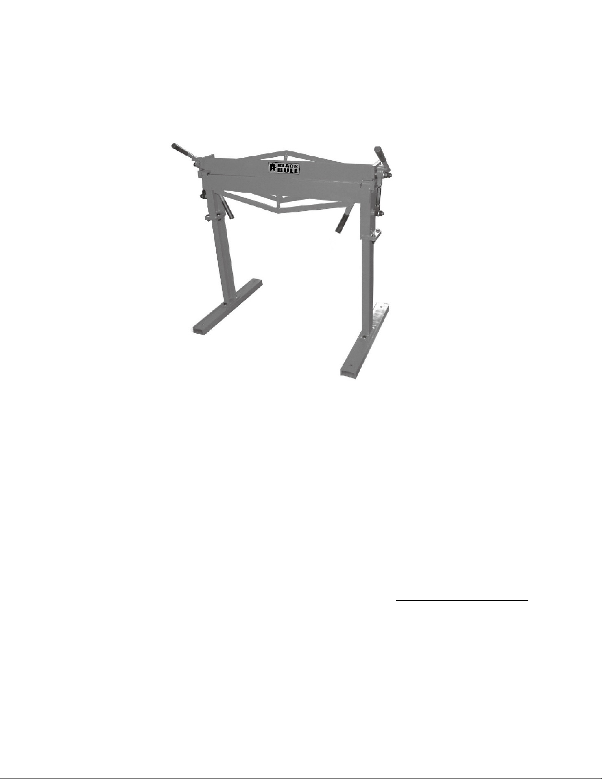
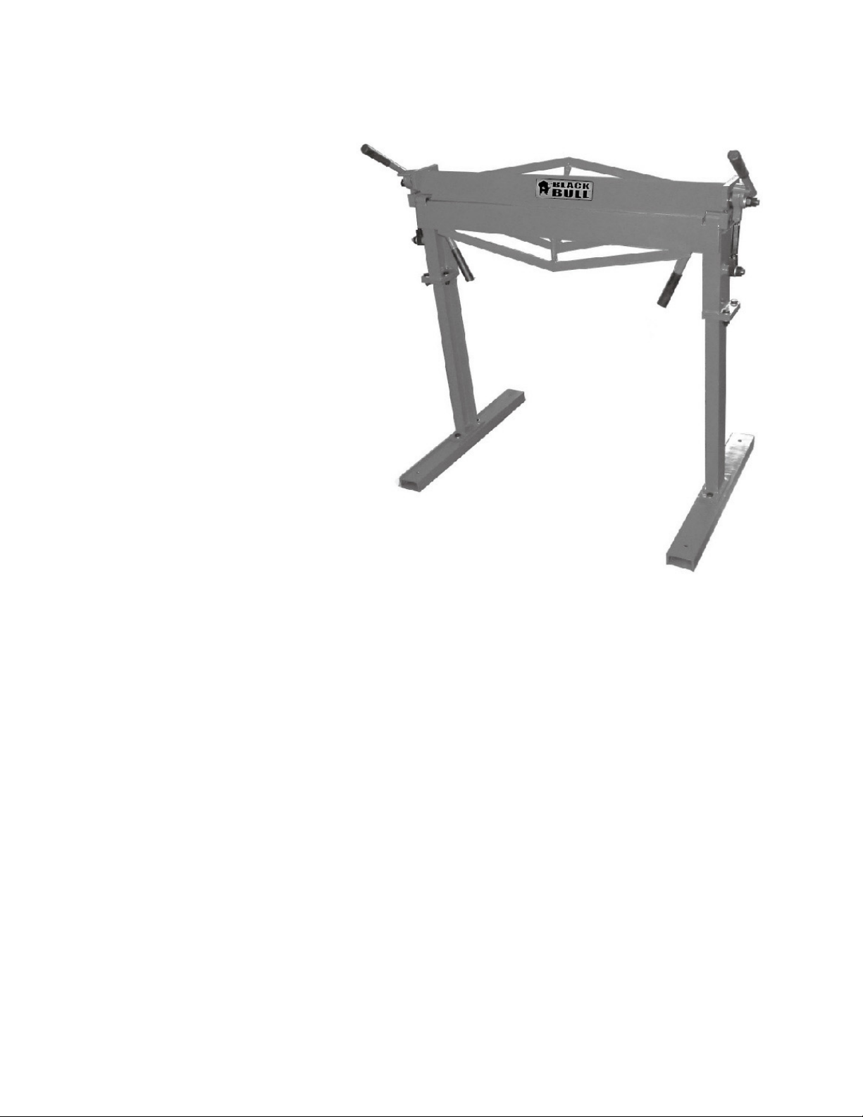
BK36
36 Inch Metal Brake With Stand
Assembly & Operating Instructions
READ ALL INSTRUCTIONS AND WARNINGS BEFORE USING THIS PRODUCT.
This manual provides important information on proper operation & maintenance. Every effort has been
made to ensure the accuracy of this manual. These instructions are not meant to cover every possible condition
and situation that may occur. We reserve the right to change this product at any time without
prior notice.
IF THERE IS ANY QUESTION ABOUT A CONDITION BEING SAFE OR UNSAFE, DO NOT
OPERATE THIS PRODUCT!
HAVE QUESTIONS OR PROBLEMS? DO NOT RETURN THIS PRODUCT TO THE RETAILER CONTACT CUSTOMER SERVICE.
If you experience a problem or need parts for this product, visit our website http://www.buffalotools.com
or call our customer help line at 1-888-287-6981, Monday-Friday, 8 AM - 4 PM Central Time. A copy of the sales
receipt is required.
FOR CONSUMER USE ONLY – NOT FOR PROFESSIONAL USE.
KEEP THIS MANUAL, SALES RECEIPT & APPLICABLE WARRANTY FOR FUTURE
REFERENCE.
Page 2

2
This is a safety alert symbol. It is used to alert you to potential personal injury hazards.
Obey all safety messages that follow this symbol to avoid possible injury or death.
This is a safety alert symbol. It is used to alert you to potential personal injury hazards.
Obey all safety messages that follow this
TABLE OF CONTENTS
RECOGNIZE SAFETY SYMBOLS, WORDS AND LABELS ............................................................... 2
SERVICE ............................................................................................................................................ 5
PACKAGE CONTENTS ...................................................................................................................... 5
COMPONENTS .................................................................................................................................. 5
ASSEMBLY ........................................................................................................................................ 6
OPERATION ...................................................................................................................................... 6
MAINTENANCE ................................................................................................................................. 7
PARTS LIST ....................................................................................................................................... 7
PARTS DIAGRAM .............................................................................................................................. 8
RECOGNIZE SAFETY SYMBOLS, WORDS AND LABELS
What You Need to Know About Safet y Instructions
Warning and Important Safety Instructions appearing in this manual are not meant to cover all possible
conditions and situations that may occur. Common sense, caution and care must be exercised when
assembling or using this product.
Always contact your dealer, distributor, service agent or manufacturer about problems or conditions you
do not understand.
symbol to avoid possible injury or death.
BK36 36 Inch Metal Brake With Stand Assembly & Operating Instructions
Page 3
3
GENERAL PRODUCT SPECIFICATIONS
FEATURES:
• 36 Inch Metal Brake
• Includes Stand
• Bends Mild Steel As Thick As 12 Gauge
• Bends Stainless Steel As Thick As 16 Gauge
SPECIFICATIONS
• Bending Angle Range 0-120°
• Easily Bolts To Workbench
KEEP THIS MANUAL, SALES RECEIPT & APPLICA BLE WARRANTY FOR FUTURE
REFERENCE.
READ ALL INSTRUCTIONS AND WARNINGS BEFORE USING THIS PRODUCT.
When unpacking, check to make sure all parts listed are included. If any parts are missing or broken,
please call Customer Service at 1-888-287-6981.
FOR CONSUMER USE ONLY – NOT FOR PROFESSIONAL USE
BK36 36 Inch Metal Brake With Stand Assembly & Operating Instructions
Page 4

4
IMPORTANT SAFETY RULES
cause you to lose control.
hands of untrained users.
Safety glasses and ear protection must b e worn during operation.
COMMON SENSE AND CAUTION ARE FACTORS WHICH CANNOT BE BUILT INTO ANY PRODUCT.
THESE FACTORS MUST BE SUPPLIED BY THE OPERATOR.
Keep your work area clean and well lit. Cluttered work benches and dark work areas may cause
accidents or injury.
Keep bystanders, children and visitors away while operating the metal bender. Distractions can
Do not force tool. Use the correct tool for your application. The correct tool will do the job better and
safer at the rate for which it is designed.
Store idle tools out of reach of children and other untrained persons. Tools are dangerous in the
Use common sense while operating this metal bender.
Do not use this tool if you are:
• Feeling tired or are under the influence of alcohol or drugs.
• Wearing loose clothing or jewelry. Keep long hair pulled back and away from moving parts.
• Overreaching or have improper footing. Handling the tool in this way could cause serious injury.
• Wear the proper safety equipment, such as safety goggles, dust masks, non-skid shoes, etc.
• Check to be sure all adjusting keys or wrenches have been removed before use.
SERVICE
Tool service must be performed only by qua lified repair personnel. Service or maintenance by unqualified
personnel could result in a risk of injury.
When servicing a tool, use only identical replacement parts and follow instructions in the manual. Use
of unauthorized parts or failure to follow Maintenance Instructions may create a risk of shock or injury.
SAVE THESE INSTRUCTIONS FOR FUTURE REFE RENCE.
This manual contains important information regarding safety, operation, maintenance and storage of this product.
Before use, read carefully and understand all warnings, cautions, instructions and labels. Failure to do so could result
in serious personal injury, property damage or even death.
BK36 36 Inch Metal Brake With Stand Assembly & Operating Instructions
Page 5

5
5
1. Upper Handles
4
1
2
3
6
7
IMPORTANT SAFETY INSTRUCTIONS
Before using this tool, you need to be come familiar with its operation. If you are unsure about the
operation of the tool, or have any questions about its proper use, call the Customer Service Department at
1-888-287-6981. Follow these instructions for safe handling of the tool:
• Be sure your work area is clean and secure. Be sure the area is free from all foreign material, nails,
staples, or any other material.
• Always use the appropriate safety gear when operating. Including but not limited to, goggles, dust
mask or respirator.
PACKAGE CONTENTS
• Metal Brake
• Stand
COMPONENTS
2. Body
3. Press Plate Assembly
4. Lower Handles
5. Mounting Foot
6. Mounting Holes
7. Stand
BK36 36 Inch Metal Brake With Stand Assembly & Operating Instructions
Page 6

6
lower handles.
ASSEMBLY
The Brake is VERY heavy and
requires that two people assist with assembly and installation.
1. Put the brake on the floor and position the mounting feet facing forward.
2. Put the left brake stand mounting pad facing against the left mounting foot. Assemble with the
bolt, washer and nut and tighten securely.
3. Put the right brake stand mounting pad facing against the right mounting foot. Assemble with
the bolt, washer and nut and tighten securely.
4. With the help of two people, lift the Brake and Stand upright.
5. Put the Brake and Stand where it will be mounted to the floor and mark through the holes on
the left and right side.
WARNING: Make sure that you will not be drilling through electrical conduit or water pipes,
before drilling the mounting holes.
6. Drill holes to the floor. Secure the brake with bolts, lock washers, & nuts (not included).
OPERATION
Do not bend stock that is thicker than 12 gauge. You will damage the Brake.
Measure the thickness before use. During bending, keep both hands on the
Lift up the Handles to open the Press Plate Assembly. Insert sheet metal that you want to bend
over the Body and under the upper Press Plate Assembly. Slide sheet metal and align the bend
marks on the metal to the inner lip of the Body.
Press down on both Handles to the locked position. This will cause the upper Press Plate
Assembly to clamp down on the stock. If the Handle does not come down all the way and lock,
either the stock is greater than 12 gauge, or the Brake needs to be adjusted to allow for a
thicker stock.
Using both hands, lift up on the Body using its lower Handles until the desired angle is reached
on the stock. Once bend is complete, return lower Handles to down position.
Lift the upper Eccentric Handles all the way up and remove the sheet metal.
MAKING ADJUSTMENTS
You may need to adjust the position of the Press Plate Assembly to allow for thicker or thinner
pieces of sheet metal, or to align it to the Body.
Adjust for Thickness of Sheet Metal
Lift the upper handles all the way up and loosen nuts to allow the bolt to move up or down.
Using an open end wrench, turn the bolt clockwise and move the Press Plate Assembly down, or
counterclockwise to move it up (for large stock).
Determine the number of turns, then tighten the nuts to secure the bolt. Repeat on opposite side.
BK36 36 Inch Metal Brake With Stand Assembly & Operating Instructions
Page 7

7
Always use caution when moving or handling the metal brake.
1
3
4
2
7
5
6
1 Handle cover 4
1. Upper Handles
Adjust bolt with the same number of turns. Press Plate Assembly must be flush with the body when
closed. If one side is not flush, readjust that side.
Align the Press Plate Assembly In or Out
Lift both upper Handles. Loosen the bolts on each side. Nudge each side of the press plate assembly
in or out. This will determine the roundness of the bend. The farther back the press plate assembly,
the rounder the bend. A typical setting should be between 1/16 to 1/8 inch behind the inner edge of
the Body.
MAINTENANCE
Lubricate all moving parts periodically. Use a light oil.
PARTS LIST
2 Left crank handle 1
3 Washer 2
4 Left eccentric bushing 1
5 Nut M10 2
6 Connecting shaft 2
7 Nut M10-turn Left 2
8 Lock nut M16 2
9 Square steel holder 2
10 Lock nut M12 6
11 Washer 12 10
12 Bolt M12X35 6
13 Shaft 2
14 Right bracket plate 1
15 Washer 1 6 4
16 Bolt M16X35 2
17 Upper press plate 1
18 Bending leaf 1
19 Leg for stand 2
20 Level plate for stand 2
21 Frame 1
22 Turning shaft 2
23 Right eccentric bushing 1
24 Right crank handle 1
25 Washer 16 2
26 Pin 3 2
27 Left bracket plate 1
28 Bolt M12X25 4
29 Bolt M12X12 2
2. Body
3. Press Plate Assembly
4. Bolt
5. Bolt
6. Nut
7. Left turn nut
BK36 36 Inch Metal Brake With Stand Assembly & Operating Instructions
Page 8

PARTS DIAGRAM
201304
8
 Loading...