

Page 1

Chapter 1 Before using WLI-T1-S11G
1.1 Introducing the Ethernet Media Converter - WLI-TI-S11G
The WLI-T1-S11G is an Ethernet Media Converter that can create a wireless connection for
a conventional Ethernet interface PC. A network printer and other network devices may also
achieve a convenient wireless connection with this product.
Ethernet Media Converter
WLI-T1-S11G
User’s Manual
Features of the WLI-T1-S11G are:
• Comply with IEEE802.11b standard realizing 11Mbps wireless communication.
• Effective range reaches 50m (Indoor Case 1), 25m (indoor case 2) or 160m (outdoor)
under 11Mbps communication.
- Indoor Case 1: Offi ce with few obstructions
- Indoor Case 1: Offi ce with few obstructions
NOTE: The effective range is adversely affected by the operating environment.
• Roaming allows you to connect to a network while mobile.
• 11 wireless channels lightnen network congestion
• Support for both 128(104)-bit and 64(40)-bit WEP. (Refer to “About WEP Encryption Recommendation of encrypted secure system” (P10)).
NOTE: If you want to use 128(104)-bit WEP key, the access point must support
128(104)-bit WEP too. You cannot combine 128(104)-bit and 64(40)-bit WEP in the
wireless network.
• An AirStation access point is required for this product.
• Connecting a WLI-T1-S11G and a hub is not guaranteed for operate correctly
■ Required Environment
OS
• Windows XP/2000/ME/98/95/NT4.0
Web Browser
• Internet Explorer 4.0 or later
• Netscape Navigator 4.0 or later
NOTE: A Web browser is required when you confi gure this product from an HTTP
interface.
■ Contents of this package
WLI-T1-S11G
AC Adapter
International AC Adapters
LAN Cable (UTP straight)
Ethernet Converter CD
User’s Manual (this manual)
- Be sure to read additional information on the seperate sheet included with the product
.
1
Page 2
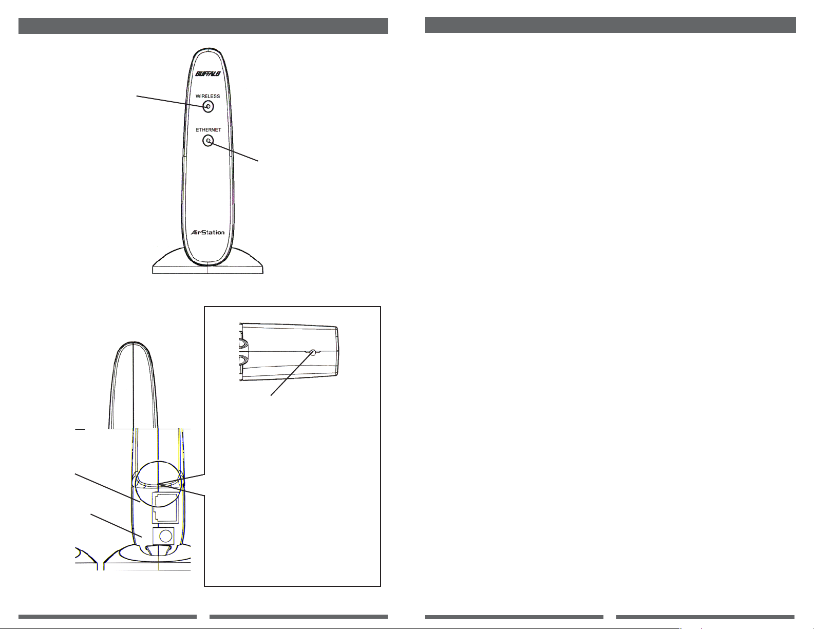
■ Checking the browser settings (only for making detailed WLI-T1-S11G settings)
Wireless LED (Green)
ON: During wireless link
Blinking: Communicating
LAN Port
Front View Diagram
Bottom View Diagram
INIT Switch
Press to initialize the WLI-T1-S11G.
Alternatively, each time the switch is
pressed, the wireless communication
mode is changed. The current mode
can be checked with the wireless LED
status immediately after the switch is
pressed.
Ethernet LED
ON: During wired link
Blinking: Communicating
Be sure to invalidate the dial-up settings and proxy settings under the browser settings.
The following procedure uses Internet Explorer 5.0 or later for example.
1. Select [Start]-[Settings]-[Control Panel].
2. Double-click the “Internet Options” icon.
3. Click the “Connections” tab.
4. When the provider information is listed in the [Dial-up settings] area, click the O mark
on the left side of [Never dial a connection] below the area to put a dot mark.
5. Click [LAN Settings] in the “Local Area Network [LAN] settings” area to confi rm the
items with a checkmark.
For memorandum, put a checkmark in the “
❑ Automatically detect settings
❑“ for the same items below.
❑ Use Automatic confi guration script
❑ Use a proxy server
❑ Bypass proxy server for local addresses
6. Upon completion of confi rming the items with the checkmark, remove the checkmark
from all the items.
1.2 About WEP Encryption - Recommendation of encrypted secure systems
Since this Ethernet Converter WLI-T1-S11G communicates using radio waves, radio
packets could be intercepted and analyzed outside. To ensure transmission security, it is
recommended to set an encryption key called a “WEP Key” in the radio packets during
communication.
This product allows for two types of WEP; 128(104)-bit and 64(40)-bit WEP.
Setting 128(104)-bit WEP (13 alphanumeric ASCII characters or 26 hex digits) assures
higher security. However, when communicating with a wireless LAN product compatible
only with 64(40)-bit WEP (5 alphanumeric ASCII characters or 10 hex digits), it is necessary to use 64(40)-bit WEP in this product.
• There are two types of encryption keys of 40-bits and 104-bits for WEP. Since 24-bit
data “initialization vector” is added to these keys during actual communication.
40-bit WEP and 104-bit WEP may also be refered to 64-bit WEP and 128-bit WEP,
DC Connector
Rear View Diagram
Blinks for a few seconds, then goes off:
Adhoc mode: Wireless PCs can communicate with
each other, however, communication is not available
with wireless LAN PCs.
Turns on for a few seconds, then off:
Infrastructure mode: Communication is available with
the AirStation.
2
3
Page 3

Chapter 2 Installing WLI-T1-S11G
This chapter describes how to make the WLI-T1-S11G settings using a Windows PC.
Step A4 Installing the WLI-T1-S11G
Upon completion of settings, connect the WLI-T1-S11G to a network printer.
Disconnect the LAN cable (UTP straight) between the PC and the WLI-T1-S11G, and
reconnect the WLI-T1-S11G to the network printer.
2.1 Overview
There are two typesof setting methods; from the wired or the wireless LAN card on the
Windows PC. Select the applicable method according to your PC confi guration.
2.2 Setup Procedure
■ Setting from a PC equipped with a wired LAN board/card
Step A1 Preparing for WLI-T1-S11G setup
1. Connect the WLI-T1-S11G to the PC’s LAN port using the included straight cable.
2. Connect the AC adapter to the WLI-T1-S11G. Be sure to use the AC adapter included
with this product.
Step A2 Installing Ethernet Converter Manager
1. Insert the “Ethernet Converter CD” into the CD-ROM drive of the Windows PC. The
installer will start automatically.
2. Click [Next].
3. Confi rm the License Agreement and click [Next].
4. Confi rm the location to install the Ethernet Converter Manager and click [Next].
5. Confi rm that a checkmark is placed for the Ethernet Converter and click [Next].
6. Click [Finish].
Step A3 Confi guring the Ethernet Converter Settings
1. Select [Start]-[Programs]-[AirStation Utility]-[Ethernet Converter]-[Ethernet Converter
Manager].
2. Select [File]-[Manual Setting].
3. Input the ESS-ID of the target AirStation into the “ESS-ID” area
(Click [Scan] to show the AirStation list).
4. Select [Communication via the AirStation] and click [OK].
5. Set the same WEP as the selected AirStation and click [OK].
6. AirStation search will start.
7. When the selected AirStation is found, communication can be made between the
WLI-T1-S11G and the AirStation.
8. Close Ethernet Converter Manager. The WLI-T1-S11G is complete.
The procedure for using your PC as a wireless PC is complete. You can use the WLI-T1S11G as is. You can check the status of the connection with the AirStation by referencing
“Checking the AirStation connection status” (on page 9).
Step A5 Verifying the WLI-T1-S11G settings
Upon completion of WLI-T1-S11G installation, verify that the WLI-T1-S11G is correctly
confi gured.
1. Select [Start]-[Programs]-[AirStation Utility]-[Ethernet Converter]-[Ethernet Converter
Manager]. Ethernet Converter Manager will be activated to automatically begin device
searching.
2. The setting is correct and complete when the WLI-T1-S11G is displayed. Click [Close}
to close the Ethernet Converter Manager.
■ Setting from a PC equipped with a wireless LAN board/card
Execute steps B1 and B2 before connecting the AC adapter to the WLI-T1-S11G.
Step B1 Installing Ethernet Media Converter Manager
Install Ethernet Converter Manager to set the WLI-T1-S11G.
Step B2 Disabling the AirStation WEP
The WLI-T1-S11G is preset to automatically connect to a nearby as the default setting,
however, no communication can be made if any WEP is set on the AirStation. In this case,
you need to disble the target AirStation WEP. By referencing the manual included with the
AIrStation, open the AirStation confi guration screen via the web browser and disable WEP
by removing the checkmark from the [Use WEP Key] box. This is a temporary setting and
should be reset to use WEP after performing steps B3 and B4.
Step B3 Preparing for WLI-T1-S11G setup
1. Connect the AC adapter to the WLI-T1-S11G.
2. The Wireless LED illuminatesfor a few seconds and then goes off.
<<When the Wireless LED blinks immediately after the AC adapter is connected>>
1. Press the INIT switch on the WLI-T1-S11G only once.
2. Confi rm that the Wireless LED illuminatesfor a few seconds and then goes off.
3. If the AirStation is near the WLI-T1-S11G, it is automatically connected and the
Wireless LED illuminates again.
<<When the Wireless LED does not illuminate>>
1. Check that the AirStation operates normally.
2. Place the WLI-T1-S11G near the AirStation.
4
5
Page 4

Step B4 Confi guring the WLI-T1-S11G settings
Confi guring the WLI-T1-S11G settings via the AirStation.
1. Select [Start]-[Programs]-[AirStation Utility]-[Ethernet Converter]-[Ethernet Converter
Manager]. Ethernet Converter Manager will be activated to automatically begin device
searching.
2. When the WLI-T1-S11G is diplayed, select it and click [Connect].
3. Input the ESS-ID of the target AirStation into the “ESS-ID’ area.
(Click [Scan] to show the AirStation list).
4. Select [Communication via the AirStation] and click [OK].
5. Set the same WEP as the selected AirStation and click [OK].
6. AirStation search will start.
7. An error message is diplayed to indicate “Logon failure” due to differences in the WEP
settings between the WLI-T1-S11G and the AirStation. Click [OK] anyway.
8. Close Ethernet Converter Manager. The WLI-T1-S11G is complete.
Step B5 Re-enabling the AirStation WEP
Re-enable the AirSattion WEP disabled in Step B2.
Open the AirStation confi guration screen via the web browser and enable WEP by insert-
ing a checkmark in the [Use WEP Key] box.
Step B6 Installing the WLI-T1-S11G
Connect the WLI-T1-S11G to shared devices such as the network printer using the LAN
cable (UTP straight).
Step B7 Verifying the WLI-T1-S11G settings
Upon completion of WLI-T1-S11G installation, verify that the WLI-T1-S11G is correctly
confi gured.
1. Select [Start]-[Programs]-[AirStation Utility]-[Ethernet Converter]-[Ethernet Converter
Manager]. Ethernet Converter Manager will be activated to automatically begin device
searching.
2. The setting is complete when the WLI-T1-S11G is complete. Click [Close] to close the
Ethernet Converter Manager.
Chapter 3 Detailed Setting
3.1 Setting the Communication Environment
■ Displaying the setting page
1. Install Ethernet Converter Manager by referencing “Installing Ethernet Converter
Manager” (on page 5).
2. Select [Start]-[Programs]-[AirStation Utility]-[Ethernet Converter]-[Ethernet Converter
Manager]. Device search will be automatically started.
NOTE: When the WLI-t1-s11g is directly connected to the PC’s LAN port, select [Edit] [Search for an Ethernet Converter] to search for the WLI-T1-S11G.
3. Select the indicated WLI-T1-S11G and then select [Settings]-[IP Setting]. Of more than
one WLI-T1-S11G is displayed, specify your WLI-T1-S11G by checking the MAC address.
4. Enter the IP address of your WLI-T1-S11G and click [OK].
5. Select your WLI-T1-S11G with its IP address set and then select [Settings]-[WEB
Setting].
6. When the network password input window appears, enter as shown below and click [OK].
- User name: root
- Password: leave blank (default setting)
(If you changed the password, be sure to input the correct password).
7. The WEB browser opens to display the settings page.
3.2 Changing and checking the settings
■ Displaying the setting page
Use the following procedure to set the encryption (WEP Key) in the WLI-T1-S11G.
1. Open the setting page
2. Click [Detailed Settings].
3. Select [On], and enter the WEP Key according to the AirStation’s WEP Ket settings.
Upon completion of the setting, click [Set].
NOTE: To communicate with a wireless LANdevice for which only one encryption
(WEP Key) can be set, enter the WEP Key to #1 only.
4. When “Setting is complete...” is displayed, setting is complete.
■ Setting the access restriction for the setting
You can set the restriction to prevent opening the setting page for wireless and wired
communications, respectively. (No search is available even from the Ethernet Converter
Manager.
1. Open the settings page.
2. Click [Detailed Settings]..
3. Click “Setting Function Access.” Click [Set].
4. When “Setting is complete...” is displayed, setting is complete.
6
7
Page 5

■ Checking the AirSattion connection status
■ Setting the IP address of the WLI-T1-S11G
You can check the connection between the PC and the AirStation with the WLI-T1-S11G
connected.
1. Install Ethernet Converter Manager
2. Select [Start]-[Programs]-[AirStation Utility]-[Ethernet Converter]-[Ethernet Converter
Manager].
3. Select [Edit]-[Search for an AirStation].
4. Confi rm that the AirStation is indicated in black characters.
5. Select [File]-[Test Connectio]-[Diagnosis].
6. Connection test will be started. Wait until “Packets sent” reaches 100.
7. Results of connection test are displayed.
After the connection status and radio signal status are determined, the diagnosis results
are displayed.
- Satisfactory: No problem in total
- Non-Satisfactory: Status is unstable
When the diagnosis results are Non Satisfactory, try the following measures.
1. Place the wireless LAN PC closer to the AirStation. (Be sure to keep a minimum distance
of 30cm).
2. Change the AirStation location.
3. Remove any object between the AirStation and the wireless LAN PC.
4. Confi rm that there is no electromagnetic interference source such as a microwave oven
near the AirStation or wireless LAN PC.
- Communication status indication = Excellent/Good/Poor/Bad
- Signal status indication = Excellent/Good/Poor/Bad/No Signal
■ Setting the setting page password
For making detailed WLI-T1-S11G settings, it is necessary to set the IP address.
1. Select [Start]-[Programs]-[AirStation Utility]-[Ethernet Converter]-[Ethernet Converter
Manager]. Device search will be automatically started.
NOTE: When the WLI-t1-s11g is directly connected to the PC’s LAN port, select [Edit] [Search for an Ethernet Converter] to search for the WLI-T1-S11G.
2. Select the indicated WLI-T1-S11G and then select [Settings]-[IP Setting].
3. Enter the IP address of your WLI-T1-S11G and click [OK].
4. Confi rm that the correct IP address is set.
5. Click [Close] to close the Ethernet Converter Manger.
Enter the IP address of your WLI-T1-S11G.
■ Restoring the WLI-T1-S11G settings to the default values
1. Open the setting page
2. Click [Device Diagnostics].
3. Click [Reset].
4. Click [Reset].
5. Follow the instructions on the subsequent pageson the computer screen.
1. Open the setting page
2. Click [Detailed Settings].
3. Click [Password].
4. Input a new password into the [New Password] fi eld and again in the [Password confi rmation]
fi eld.
Even is a password is currently set, nothing is displayed in the password fi eld of this page.
Click [Set] only to change the password. If you click [Set] with this fi eld blank, , the current
password will be deleted.
For the password, you can enter up to eiight alphanumeric characters and the underscore.
Thes characters are case sensitive.
If you lost your password, you can press the INIT button on the AIrStation to reset it to the
default password. If the INIT button is used, all other settings will be reset to the default
factory settings, changing the wireless communication mode.
For more information about the INIT switch, see ”Component names and Functions.”
NOTE: If you have set a new password, you will be prompted to enter the password each
time the setting page is opened.
See Section 3.1, number about inputting the password.
8
9
Page 6

Chapter 4 Specifi cations
Product Specifi cations
Notes
Wireless LAN
Interface
LAN Interface
Power / Current
consumption
Operating
Temperature /
Humidity
Weight
Dimensions
Conforming Standards
Data Transfer Method
Data Transfer Rate
Access Method
Frequency Range
(Mid-Frequency)
Communications
Distance
(Depending on ambient
conditions)
Conforming Standards
Data Transfer Rate
Data Transfer Mode
Port
3W(Max) / 700mA(Max)
0˚C to 40˚C / 20% to 80% (no condensation)
120g (without AC Adapter)
58mm x 120mm x 89mm (W x D x H)
IEEE802.11b (Wireless LAN Standard Protocol
FCC 15.247
ETS300-328
DS-SS Simplex (Half Duplex)
1, 2, 5.5, 11Mbps (Auto Sense)
Infrastructure Mode / Adhoc Mode
2,412 to 2,484 MHz
*No confl ict with cell or cordless phones, Radio
or Television.
25m indoors, 50m outdoors at 11Mbps
35m indoors, 70m outdoors at 5.5Mbps
40m indoors, 90m outdoors at 2Mbps
50m indoors, 115m outdoors at 1Mbps
IEEE802.3 (10 Base-T)
10Mbps
Half Duplex
RJ-45
10
11
 Loading...