

Page 1

AirStation™ Quick Setup Guide
54 Mbps* Wireless Compact Repeater Bridge
WLA2-G54C
WLA2-G54C
This Quick Setup Guide will guide you through quickly and easily installing this
product. For detailed setup and configuration instructions please refer to the
Online Manual on the AirNavigator CD-ROM.
Contents
◗ 54 Mbps* Wireless Compact Repeater Bridge (WLA2-G54C)
◗ Utility CD-ROM with User Manual
◗ Quick Setup Guide
◗ AC Adapter with International Adapters
◗ 7 ft. Ethernet Cable
◗ Wall Mount Kit with Screws
◗ Warranty Statement
If any items are missing, please contact the reseller or retailer from whom you purchased this product.
System Requirements
◗ Desktop or Laptop PC with an Ethernet Adapter or Wireless Adapter
Installed
◗ Existing Local Area Network to Connect to the AirStation
www.buffalotech.com
PY00-29044-DM20
Page 2

MAC Address and SSID
The LAN or Wired MAC address is the
AirStation ID and is located on the rear
of the AirStation.
The Wired MAC address is the default
SSID of the AirStation.
The MAC address is the 12 digit code
comprised of numbers and letters.
2
Page 3
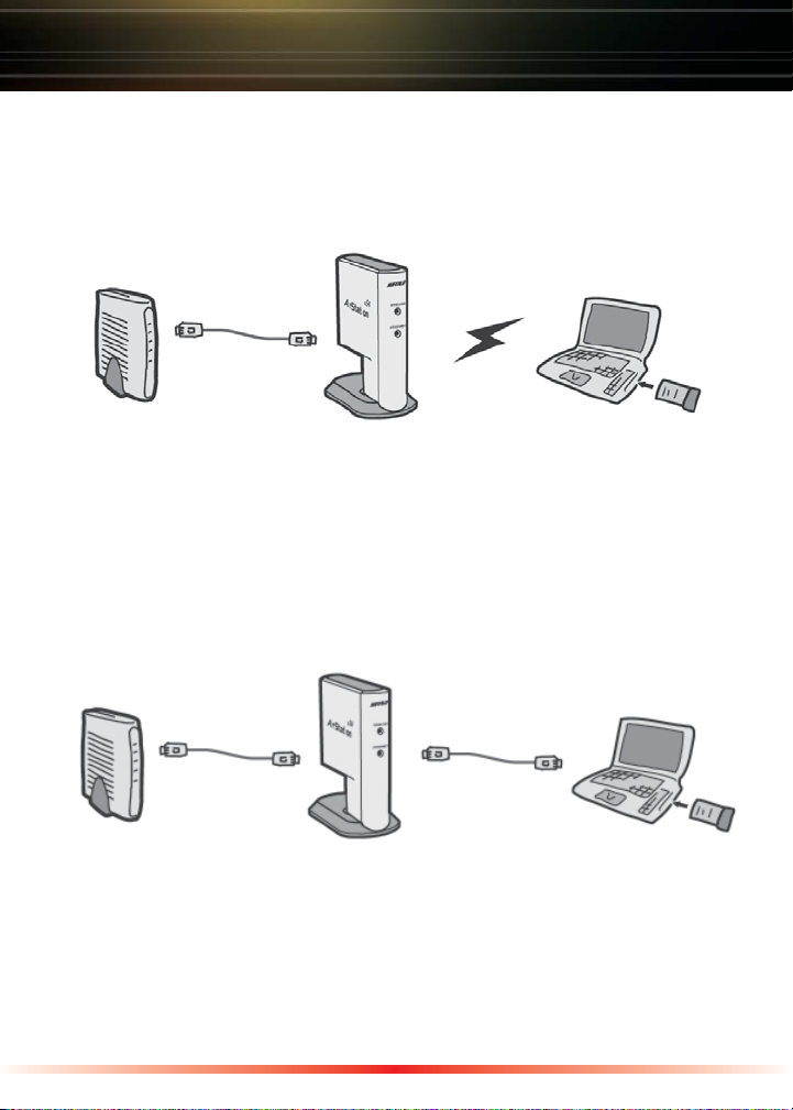
Connecting Cables to the AirStation
Carefully following the instructions for connecting cables to your AirStation is
key to a quick and simple initial setup.
Wireless Connection
DSL/Cable Modem AirStation Wireless Laptop
(Router)
Plug the provided 7 ft. Ethernet cable into the LAN port on the AirStation and
plug the other end into a hub, switch, or router on your Local Area Network .
Power on the AirStation. Wait for the green wireless and Ethernet lights to stop
flashing before trying to configure the AirStation.
Wired Connection
AirStation Connected Computer
Plug the provided 7 ft. Ethernet cable into the LAN port on the AirStation and
plug the other end into a hub, switch, or router on your Local Area Network.
Plug another Ethernet cable into the port on your computer's Network Interface
Card (NIC).
Power on the AirStation. Wait for the green wireless and Ethernet lights to stop
flashing before trying to configure the AirStation.
3
Page 4

Decide on a Mode for Initial Connection to the AirStation
Buffalo recommends using a wired connection for initial configuration, meaning
your computer is physically connected to the AirStation with an Ethernet cable
plugged into the LAN port of the WLA2-G54C and to a network computer. This
type of setup will eliminate possible wireless setup problems due to any issues
with the wireless adapter on the computer being used to configure the bridge.
If there is not an Ethernet adapter available on the computer being used to
configure the bridge, wireless configuration may be performed using a correctly
installed 802.11b or 802.11g wireless adapter (see the next page for instructions
on this).
Configuring the AirStation using a wired connection
When using a wired connection, the first step is to manually configure an IP
address for the network adapter on your computer. This is done by:
Windows 98SE
- Right-click on Network Neighborhood or
My Network Places and select Properties
- Select the Configuration tab, scroll down
to TCP/IP- -> Wireless LAN Adapter
and press Properties
- Specify an IP address
- IP address = 192.168.11.2
- Subnet mask = 255.255.255.0
- Click OK to close Internet Protocol (TCP/
IP) Properties
- Close the Network Connections window
Windows 2000/ME/XP
- Right-click on the Network Connection
inside of the Network Connections window and select Properties. Network
Connections can be found in the PC's
Control Panel.
- Scroll down to Internet Protocol (TCP/IP)
and press Properties
- Select Use the following IP address
- IP address = 192.168.11.2
- Subnet mask = 255.255.255.0
- Click OK to close Internet Protocol (TCP/
IP) Properties
- Close the Network Connections window
4
Page 5

Decide on a Mode for Initial Connection to the AirStation
Configuring the AirStation using a Wireless connection
Please consult with your wireless client card manufacturer on the proper setup
and operation of your client card. You will need to wirelessly associate to the
WLA2-G54C by connecting to its SSID (Refer to Page 2 of this Quick Setup
Guide for more Information).
Before you attempt to connect to the AirStation's Configuration Pages, you must
first manually configure an IP address on your computer. This is done by:
Windows 98SE
- Right-click on Network Neighborhood or
My Network Places and select Properties
- Select the Configuration tab, scroll down
to TCP/IP- -> Wireless LAN Adapter
and press Properties
- Specify an IP address
- IP address = 192.168.11.2
- Subnet mask = 255.255.255.0
- Click OK to close Internet Protocol (TCP/
IP) Properties
- Close Network Connections window
Windows 2000/ME/XP
- Right-click on Wireless Network
Connection and select Properties
- Scroll down to Internet Protocol (TCP/IP)
and press Properties
- Select Use the following IP address
- IP address = 192.168.11.2
- Subnet mask = 255.255.255.0
- Click OK to close Internet Protocol (TCP/
IP) Properties
- Close Network Connections window
5
Page 6

AirStation Configuration
After you have configured the network adapter properties and are connected
or associated to the wireless bridge, Basic and Advanced configurations can
be made to customize internal and external connections. A convenient web
browser interface is included on the bridge to allow these modifications. Launch
a web browser window such as Internet Explorer or Netscape Navigator to
configure the AirStation. In the Address field of the web browser window,
type in http://192.168.11.100 and click “Go” or enter to access the browser
configuration interface. If you have previously modified the LAN IP address,
enter the custom IP address instead. If
the IP address has been lost / forgotten
press the red INIT button on the bottom
face of the AirStation for several seconds
until the red DIAG light illuminates. This
will restore the bridge to default factory
settings.
Note: If you cannot access the interface, verify that you have correctly
connected the AirStation’s cables and followed the previous steps. Otherwise,
please contact Buffalo Technical Support through one of the options listed at the
end of this guide.
6
Page 7

AirStation Configuration
At this point, you will need to enter a User name and password. Enter “root ”
as the User name and leave the password field blank. Click OK to enter the
configuration page.
From here you can configure LAN IP settings, encryption, etc.
Note: If you cannot access the interface, verify that you have correctly
connected the AirStation’s cables and followed the previous steps. Otherwise,
please contact Buffalo Technical Support through one of the options listed at the
end of this guide.
This completes the basic AirStation Configuration. To change advanced
settings consult the Online Manual on the AirNavigator CD-ROM or your ISP for
more information.
Once configuration has been completed and the AirStation is configured
properly, it is important to return the network properties back to "Obtain an
IP address automatically". This can be done by accessing the Network
Connection info as seen on Page 4 and Page 5 of this Quick Setup Guide, and
selecting, "Obtain IP address automatically" from the TCP/IP options.
7
Page 8

Using AOSS
AOSS (AirStation One-Touch Secure System™) is a simple, one-touch setup for
connecting wireless clients to an access point while setting up the most secure
possible connection. Users no longer need to worry about choosing the proper
security protocols, IP addresses, or ESS-ID's. The intelligence of AOSS
determines the most optimal connection and configures itself in seconds.
Note: AOSS automatically creates a secure connection between your AOSS Access
Point and client. You must have a Buffalo AOSS enabled wireless client device to use the
AOSS features of your AOSS Access Point/Router.
◗ Configure your WLA2-G54C's network connection by referring to the above
mentioned instructions.
◗ Once the WLA2-G54C has been configured, follow the directions to install
your wireless client device and its drivers if necessary. Certain wireless client
adapters require client software to configure them. If your device has a Client
Manager, then install it as well.
Note: If the wireless client adapter is
installed on a PC, then the AOSS client
manager will need to be installed as
well. If your wireless client adapter is a
standalone device that does not require a
PC, then just power up the device.
Standalone Devices:
Ethernet Converters and
Access Point Bridges
Client Manager Devices:
CardBus, USB, and PCI Adapters.
Standalone Client Manager
AOSS Device Device
8
Page 9

Using AOSS
continued
◗ Now that the WLA2-G54C and wireless
client adapter are installed, you can use
AOSS to configure them.
◗ To begin the configuration, press the AOSS
button on the side of the WLA2-G54C
chassis until the AOSS LED on the front
begins to flash.
AOSS Mode is now active.
Note: AOSS mode will stay active for a period of two minutes. This is the time-slot
required to initiate the wireless client adapter.
◗ Refer to your wireless client adapter's AOSS supplement to initiate the
wireless client adapter's AOSS mode.
◗ Once the client adapter has begun communicating with the AOSS router, the
AOSS client will report a successful AOSS connection. This indicates that the
AOSS process has begun and the two devices are configuring themselves.
At this time, the AOSS Light on the WLA2-G54C will become solid. Please
refer to your wireless client adapter's supplement for the remainder of the
setup.
Additional AOSS Information:
◗ Only one AOSS wireless client adapter can be configured to the AOSS
access point at a time. Thus, the button will need to be repressed for each
additional AOSS wireless client adapter that will be connected.
◗ It is not necessary to AOSS client devices that have already been configured
via AOSS, unless significant changes have been made to the wireless
network.
◗ Do not attempt to configure two separate AOSS networks at the same time,
as it may cause undesired configurations.
◗ If an undesired client has connected via AOSS, it can be disconnected from
within the WLA2-G54C's advanced configuration AOSS menus.
9
Page 10

Buffalo Technology
Technical Support
Buffalo Technology offers toll-free technical support 24 hours a day, 7 days a
week for this product. Customers in the United States and Canada can obtain
technical support using the following information:
◗ Web USA http://www.buffalotech.com/wireless
EUROPE http://www.buffalo-technology.com
CHINA http://www.buffalo-china.com
TAIWAN http://www.buffalo-tech.com.tw
KOREA http://www.buffalotech.co.kr
The constantly evolving state of wireless products and operating systems
requires Buffalo Technology to occasionally release updated software to take
advantage of new technologies and to comply with industry standards. For
the most recent software, firmware, driver, and technical whitepaper releases
available, please visit the Buffalo Technology website.
FCC Compliance Statement - This device complies with Part 15 of the FCC
Rules. Operation is subject to the following two conditions: (1) This device may
not cause harmful interference, and (2) this device must accept any interference
received, including interference that may cause undesired operation.
R&TTE Compliance Statement - This equipment complies with all
the requirements of the DIRECTIVE 1999/5/EC OF THE EUROPEAN
PARLIAMENT AND THE COUNCIL of 9 March 1999 on radio equipment and
telecommunication terminal equipment and the mutual recognition of their
conformity (R&TTE). See the user manual for the complete statement.
* 54Mbps is the IEEE802.11g standard theoretical maximum and does not
represent actual data throughput.
10
 Loading...