

Page 1

AirStation™ VPN Setup Guide
WZR-RS-G54
WZR-RS-G54
Introduction
The WZR-RS-G54’s VPN services allows users to securely access their home or office
network from anywhere in the world. All services available in your network are one click
away with the use of the WZR-RS-G54’s “Network Service List”. You can even turn on your
computer remotely to gain access to your files, printers, and directly to the desktop for
complete control. The WZR-RS-G54 PPTP (VPN) server can host up to 100 user accounts
for remote access to local resources. Create accounts for all your friends and family.
www.buffalotech.com/wireless
PY00-29028-DM20
Page 2

Complete Router Configuration
Before you begin to setup the PPTP Server and VPN Client you must first setup your
network. Please refer to the WZR-RS-G54 Quick Setup Guide and/or Manual to configure
the WZR-RS-G54. Once the WZR-RS-G54 is configured, record the WAN Port IP
Address, as you will need it later.
This can be found in the
‘Advanced’-> ‘Management’ ->
‘System Information’ section in the
WZR’s user interface. If you have a
dynamically assigned WAN IP
Address you may want to register
with a Dynamic DNS service so you
do not have to keep referring to the
“System Information” page to check
the WAN Port IP Address.
Dynamic DNS Services
Dynamic DNS Services provide the
ability to register a “vanity”URL, so
you do not have to remember your
public IP address. Example
http://YourName.dyndns.com
Some providers will provide this
service for free. The WZR-RS-G54
supports DynDns and TZO Dynamic
DNS services.
Refer to the WZR-RS-G54 Manual
found on the CD for more specific
information on how to configure the service.
2
Page 3
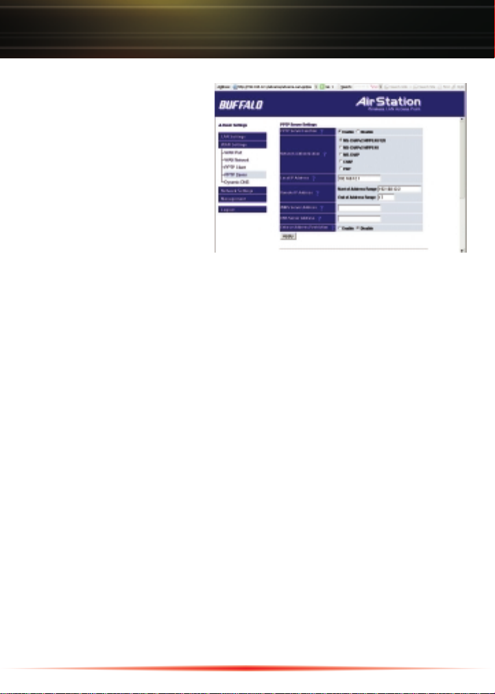
PPTP Server Setup
The PPTP Server Setup is required
if you wish to utilize the features of
the “Network Service List”.
◗ To utilize the feature select
‘Enable’.
◗ Select the type of authentication
desired. The default setting of
“MS-CHAPv2-MPPE-40/128” is
supported by all Microsoft dial up
clients. This is the recommended
setting.
◗ Input the IP Address of the LAN port in the ‘Local IP Address’ field. The LAN port
default setting is 192.168.12.1. (This field is required.)
◗ Set the range of IP Addresses to supply to VPN Clients in the ‘Remote IP Address’
fields. This can be the same range as the DHCP server or you can set a separate
range specifically for the VPN Clients. (This field is required.)
◗ If desired, add a WINS Server Address in the ‘WINS Server Address’ field. (This field
can be left blank.)
◗ If desired, add a DNS Server IP Address in the ‘DNS Server Address’ field. It is
recommended to add the DNS Server info if in an Active Directory Domain. (This field
can be left blank.)
◗ If you wish to restrict inbound connections based on the Remote IP Address click on
‘Enable’ in the ‘Enforce Address Restriction’ field. After pressing ‘Apply’, scroll to
the bottom of the page to register the allowable addresses.
Press ‘Apply’ to register your settings in the router.
3
Page 4

Add Usernames and Passwords to the Database:
◗ Click on the ‘Add New User’button.
A window will appear to add the new
user.
◗ Enter a ‘User Name’. It can be up to
16 characters. Alphanumeric
characters, double quotation ("), single
quotation ('), slash (/) and any symbol
other than space may be used.The
username is case sensitive.
◗ Enter a ‘Password’. Re-enter the password to confirm. It can be up to 16 characters.
Alphanumeric characters, double quotation ("), single quotation ('), slash (/) and any
symbol other than space may be used.The password is case sensitive.
◗ Select the ‘IP Address Assignment Method’ from the drop down list. You have 3
choices.
• Acquire Automatically with DHCP – The next available address in the DHCP
servers list will be offered to the client.
• Obtain from PPTP Server settings range – An IP Address will be given from the
list you created in the PPTP Server’s remote IP addresses list.
• Fixed IP Address – This option allows you to enter the fixed IP Address for the user
in the Fixed IP Address field.
◗ Enable/Disable RIP Transfer. The default setting is “Disable”. Enable this feature if you
desire to pass RIP packets to the remote user. This setting would be used if the
AirStation is also configured as a VPN endpoint (client).
Press the ‘Apply’ button to register the user. You can register up to 100 users. VPN user
status can be seen in the registered user list. An LED on the front of the AirStation (below
the WAN LED) will illuminate when a user has initiated a VPN session.
4
Page 5

Allowable Address List:
This list is used to register remote IP Addresses that are authorized to connect to the
PPTP Server. These IP Addresses are required if ‘Enforce Address Restriction’was
enabled above.
Setting up your Computer as a VPN Client
A VPN Client is required to communicate with a VPN Server. You will need to install a
VPN Client on each computer that wishes to log in to the PPTP Server. You may want to
keep this setup guide handy for a quick reference to set up remote computers from a
remote location. The setup is performed once for each computer.
Windows 98SE / ME
Setting up a Windows 98SE/ME computer as a VPN Client is performed in two steps.
Step one is to setup the VPN Adapter. Step two is to configure the VPN Client. You will
need your Windows 98SE/ME CD to complete the installation.
Windows 98SE VPN Adapter installation
Installing the VPN Adapter
◗ Right click on the Network
Neighborhood icon and
select ‘Properties’.
◗ You will be directed to the
following page.
◗ Press ‘Add’.
5
Page 6

Windows 98SE VPN Adapter installation cont'd
◗ Click on ‘Adapter’ to highlight.
◗ Press ‘Add’.
◗ Scroll down and select ‘Microsoft’in
the Manufacturers column.
◗ Select ‘Microsoft Virtual Private
Networking Adapter’ and press the
‘OK’ button. You will be prompted to
insert your Windows 98SE CD to
complete the installation of the adapter.
When the installation is complete, you will be prompted to reboot your computer.
Windows ME VPN Adapter Installation
Installing the VPN Adapter
◗ Click the ‘Start’ menu, click
‘Settings’, click ‘Control Panel’,
and then double-click ‘Add/Remove
Programs’.
◗ Click the ‘Windows Setup’tab.
◗ Click ‘Communications’, press the
‘Details’ button, click to select the
‘Virtual Private Networking’ check
box and then press the ‘OK’button.
◗ Press ‘OK’, and then ‘Yes’ to restart
your computer.
6
Page 7

Windows 98SE / ME Dial-Up Networking Client installation
Configure the Dial-Up Networking client
◗ Double click on your ‘My Computer’
icon.
◗ Double click on ‘Dial-Up Networking’
icon. (ME users click the ‘Dial-Up
Networking’ link.)
◗ Double click the ‘Make New
Connection’ icon.
◗ Type a name you wish to use to refer
to the connection. Use the drop down
selector to select ‘Microsoft VPN
Adapter’. Press the ‘Next’ button.
7
Page 8

Windows 98SE / ME Dial-Up Networking Client installation continued
◗ Type in the Dynamic DNS Host Name
or WAN IP Address of the VPN Server.
The WAN IP Address was referred to
on page 2. Press the ‘Next’ button.
◗ Click ‘Finish’.
This completes the Windows 98SE / ME VPN Client setup. You are now ready to establish
a remote VPN connection to your WZR-RS-G54.
Connecting to the Remote Network
Be sure that you have a valid internet connection before trying to connect remotely.
◗ Double click on the ‘Dial-Up
Networking’ Icon you created.
Type in the username and password that
was created in the PPTP Server. Verify
you have the correct IP Address and
press on the ‘Connect’ button. You will
receive feedback that the connection is
successful.
NOTE: To alter the properties of the VPN Client, where internet requests are routed
through your internet connection and not the VPN connection, refer to the following
procedure.
◗ From the ‘Dial-Up Networking’ page
Right Click on the VPN Client you just
created.
8
Page 9

Connecting to the remote network
◗ Select ‘Properties’.
◗ Click on the ‘Server Types’ tab.
◗ Press the ‘TCP/IP Settings’ button.
◗ Un-check ‘Use default gateway on
remote network’ check box. This
means, if you have an active VPN
session and you also wish to visit a
web site, your web request does not
go through the VPN tunnel.
9
Page 10

Windows 2000 / XP
Microsoft has provided a wizard to easily configure the VPN Client in Windows 2000/XP.
Starting the wizard in Windows XP is different from Windows 2000. Once the wizard
launches, the setup is very similar; the images on your computer may be slightly different
from what you see in this publication.
Starting the Windows 2000 wizard:
◗ Click on the ‘Start’ menu, go to
‘Settings’, then to ‘Network and
Dial-Up Connections’, and click
‘Make New Connection’.
Starting the Windows XP Wizard:
◗ Click on ‘Start’ and select ‘Control
Panel’.
◗ Click ‘Network and ◗ Click ‘Create a connection to the
Internet Connections’. network at your workplace’.
10
Page 11

For both Windows 2000/XP
◗ Click the ‘Next’button.
◗ Click ‘Connect to a private network
through the Internet’.
◗ Press the ‘Next’ button.
◗ If you have to dial out to get an internet
connection, then select ‘Automatically
dial this initial connection’ and use the
drop down selector to select the
connection. If not, select ‘Do not dial
the initial connection’. The ‘Do not
dial the initial connection’ option
should be selected if you are using a
broadband connection.
◗ Click ‘Next’.
◗ Type in the IP Address of your WAN IP
or Dynamic DNS Host Name for the
Destination Address.
◗ Press the ‘Next’ button.
11
Page 12

◗ Depending on your computer
configuration select either ‘For all
users’ or ‘Only for myself’.
◗ Press the ‘Next’ button.
◗ Type a name you wish to use to identify
the connection.
◗ Leave the check box checked if you wish
for a shortcut to be created on your
desktop for this connection. Otherwise
un-check the box.
◗ Press the ‘Finish’ button.
Windows 2000
◗ A window will pop up so you can initiate
the VPN connection. You can press
‘Connect’ to dial the connection after
inputting your user name and password
or press ‘Cancel’ to close the window
and dial the connection later.
This completes the setup of the VPN Client
on your Windows 2000/XP computer.
12
Page 13

Using the Windows XP VPN Client:
◗ Double click on the icon shortcut you
created on your desktop or browse back
to your ‘My Network Connections’ for
the VPN Client icon and double click on
it. Type in your user name and password
(set up on the PPTP Server) and click
connect.
NOTE: It is not recommended to use the save password feature for your VPN Client. If
your computer were to be stolen, then an unauthorized user may gain access to your
network.
NOTE: To alter the properties of the VPN Client where internet request are routed
through your internet connection and not the VPN connection, refer to the following
procedure.
Windows 2000 / XP:
◗ Launch the VPN Client. Press the
‘Properties’ button. Select the
‘Networking’ tab.
◗ Highlight ‘Internet Protocol (TCP/IP)’
and press the ‘Properties’ button.
Press the ‘Advanced’ button.
◗ Un-check ‘Use default gateway on
remote network’. Press the ‘OK’ button
to close all the windows.
13
Page 14

Network Service List
Once the VPN session is established you can now take advantage of the “Network Service
List” to provide quick access to all of your network resources. You can access this list by
opening up an Internet Explorer Web Browser (5.0 or greater) typing the LAN IP Address
for your WZR-RS-G54 followed with “/hosts.htm”.Ex. http://192.168.12.1/hosts.htm . The
default IP Address for the LAN is 192.168.12.1.
NOTE: Web browsers other than Microsoft Explorer can be used to access this page but
some of the one click features may become disabled.
You can refer to the help section (Blue Question Mark) or the WZR-RS-G54 Manual (on
the CD-ROM) for further information on “Network Service List” function.
14
Page 15

Buffalo Technology
Technical Support
Buffalo Technology offers toll-free technical support 24 hours a day, 7 days a
week for this product.Customers in the United States and Canada can obtain
technical support using the following information:
◗ Web www.buffalotech.com/wireless
◗ E-mail help@buffalotech.com (Retail Channel Customers)
info@buffalotech.com (All other Customers)
◗ Telephone 866-752-6210 (USA & Canada only)
The constantly evolving state of wireless products and operating systems
requires Buffalo Technology to occasionally release updated software to take
advantage of new technologies and to comply with industry standards. For the
most recent software, firmware, driver, and technical whitepaper releases
available, please visit the Buffalo Technology website.
FCC Compliance Statement - This device complies with Part 15 of the FCC
Rules. Operation is subject to the following two conditions: (1) This device may
not cause harmful interference, and (2) this device must accept any interference
received, including interference that may cause undesired operation.
R&TTE Compliance Statement - This equipment complies with all the
requirements of the DIRECTIVE 1999/5/EC OF THE EUROPEAN PARLIAMENT
AND THE COUNCIL of 9 March 1999 on radio equipment and
telecommunication terminal equipment and the mutual recognition of their
conformity (R&TTE). See the user manual for the complete statement.
Copyright © 2004 Buffalo Technology, Inc. All Rights Reserved. Buffalo Technology (USA) Inc., is part of MELCO INC.,
the global manufacturers of IT peripherals, including memory, networking, and multimedia products, inside many of the
world's computers. All trademarks are property of their respective owners.
15
 Loading...