

Page 1
Wireless USB 2.0
www.buffalotech.com/wireless
User Manual
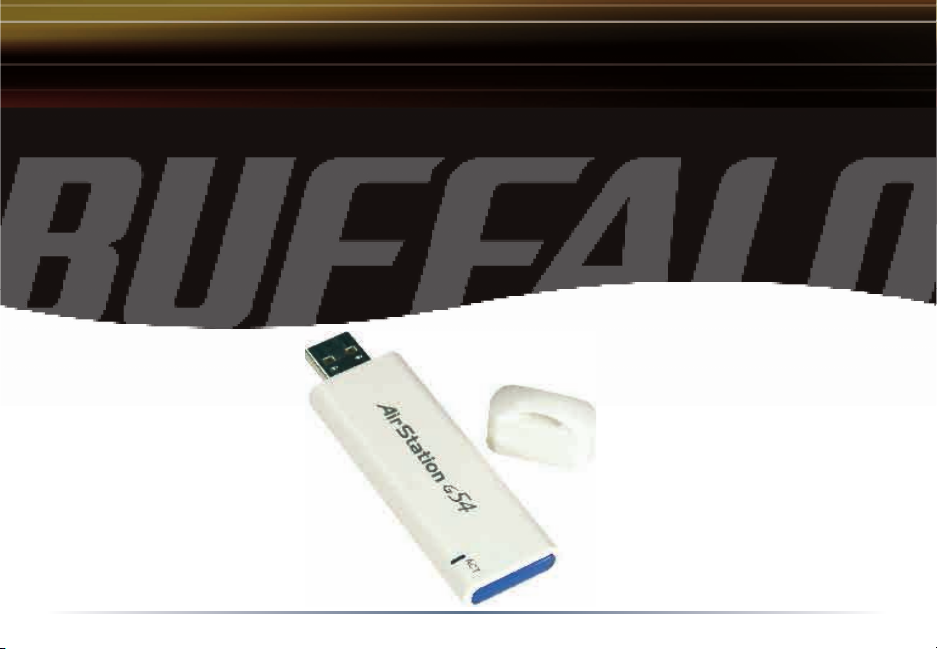
Buffalo AirStation™
Adapter
WLI-U2-KG54AI
Page 2

Install Options
The USB Keychain has a unique Auto Install feature. By default, this is enabled and the keychain
adapter will automatically load its driver and software from internal memory.
If the feature is disabled, it will be necessary to intall the adapter from the AirNavigator CD inserted into
your CD-ROM drive.
To disable the Auto Install feature, use a paperclip of other pointed object to move the small
switch to the far left. If the small switch is on the right side over the black circle, Auto
Install is enabled (default setting).
2
Page 3
Installation
Wireless USB 2.0 Adapter
Installation & Configuration
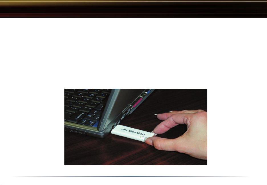
1. Installing the Wireless USB 2.0 Adapter:
� Insert the USB Adapter into your Laptop or Desktop PC as shown. USB ports
may be located on the rear, front or side of your PC depending on the design.
If there are multiple ports, choose the port that is free of interference to
maximize antenna rece
ption.
3
Page 4
Installation
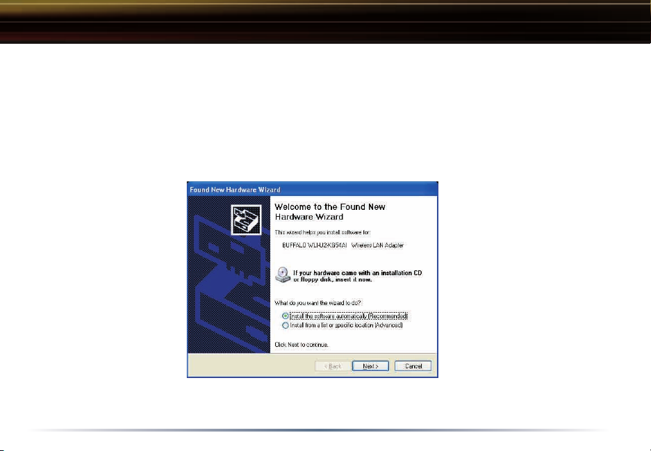
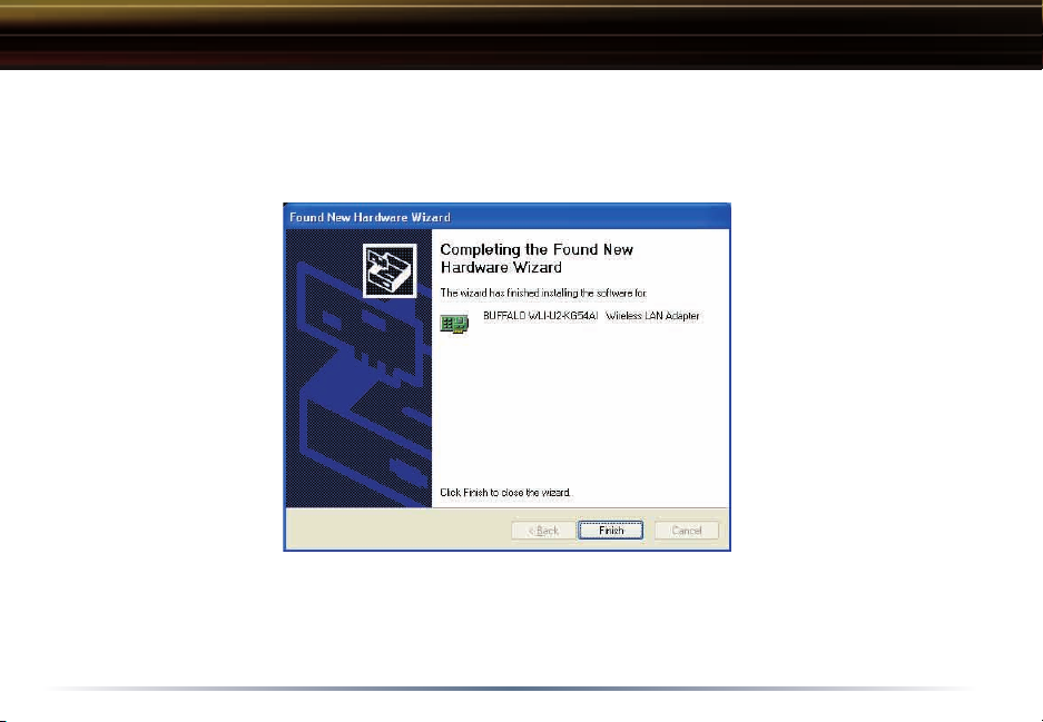
2. Device Discovery:
� Once inserted, Windows will automatically discover the presence of new
hardware. Various popup clouds will appear from the Windows taskbar. During
this time, allow Windows and the Wireless USB Adapter to communicate. The
process should take about one minute
.
Click Next
Auto Install the driver installation screens will be automatically acknowledged.
if the Found New Hardware Wizard appears as shown above. If using
4
Page 5

Installation
3. Wireless Adapter Driver Installation:
� In Windows XP or 2000, the following dialog box may appear as drivers are
installed. If so click Yes or Continue Anyway to finish installing the necessary
drivers. If using Auto Install the driver installation screens will be automati
cally acknowledged.
Windows 98SE/ME/2000 users should skip to page 9.
-
5
Page 6
Completing Installation on Windows XP
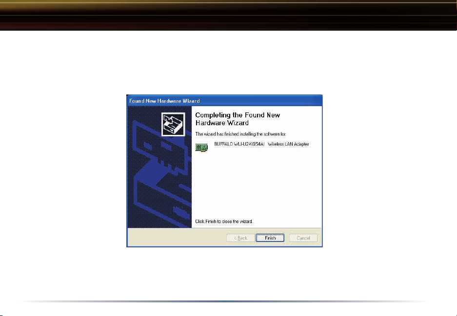
4. Completing Driver Installation for Windows XP:
� When the driver has completed installing on a Windows XP PC click Finish.
If you wish to use Windows Wireless Zero Configuration Service click No on the
next dialog box and go on to page 6. Otherwise, click Yes on the dialog box to
install Buffalo’s Client Manager
and go on to page 10.
6
Page 7
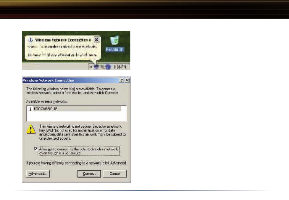
Using Wireless Zero Configuration Service
3. Configuring Wireless Zero Configuration
Service:
� If the Wireless Zero Configuration Service
is activated, Windows will scan for available
wireless access points once the Wireless
PCI Adapter is properly installed. If Windows
detects one or more access points, a network-
ing icon appears on the task bar. One or more
wireless networks are available appears as a
caption accompanying the icon.
n Note: If the Wireless Zero Configuration Service is not functioning, select Start>Control
Panel>Administrative Tools>Services. Select
Automatic in the Startup Type field of Wire
less Zero Configuration Service to enable
the Wireless Zero Configuration Service. The
default value of Wireless Zero Configuration
Service is Automatic.
� Right click the networking icon in the taskbar
and select View Available Wireless Networks to
display a list of available wireless networks.
Select an access point network name and click
the Connect button to establish a connection.
7
-
Page 8
Using Wireless Zero Configuration Service
� Click the Advanced button to enter an SSID network name or WEP/WPA en-
cryption key, if either is necessary. To add an SSID network name that is not
8
Page 9
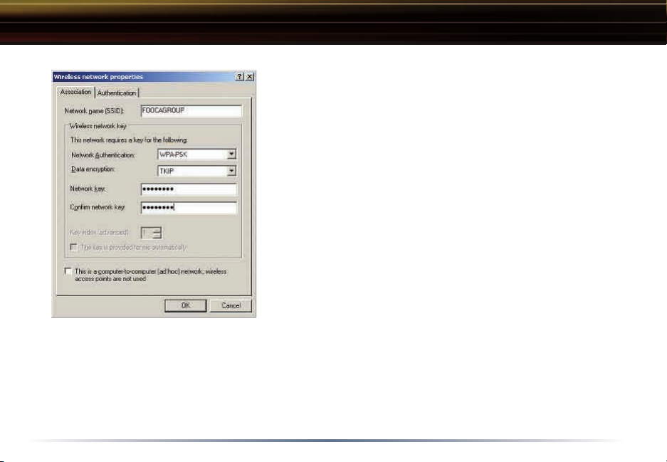
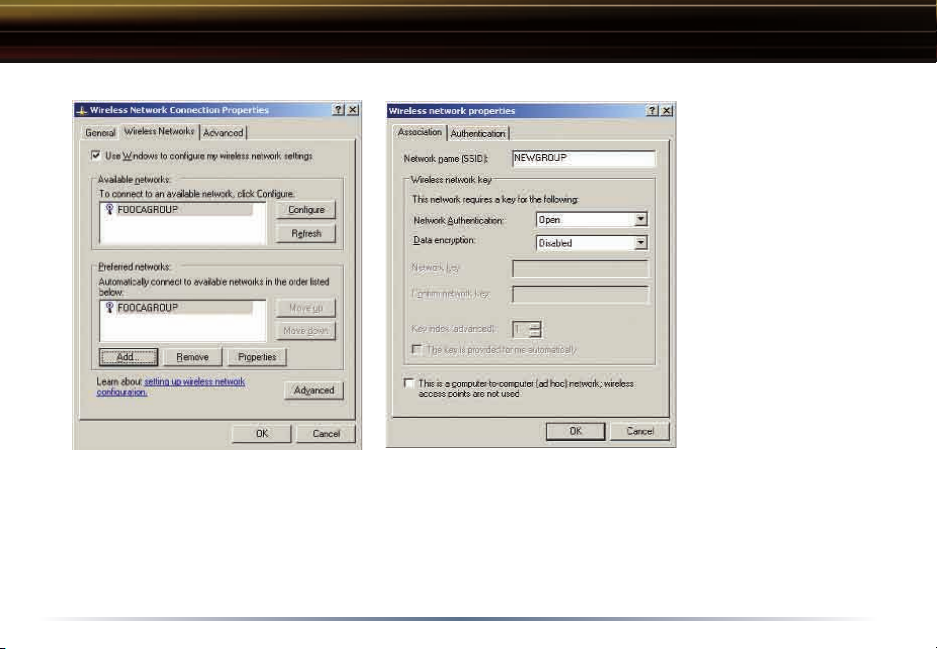
Using Wireless Zero Configuration Service
� To configure a WEP/WPA encryption key, select
the appropriate wireless network and click the Configure button.
� From the pull down menu, select the appropriate
Network Authentication and Data Encryption for the
wireless network. Enter and confirm the Network
Key and Key Index. Click the OK button when
finished.
n Note: Buffalo Technology recommends that
users of the Wireless Zero Configuration Service
upgrade to the latest version freely available at:
http://www.microsoft.com
For advanced support in using Window’s XP’s
Wireless Zero Configuration Service, refer to the
Buffalo Support Web Site: http://www.buffalotech.
com/wireless/support
Skip to Page 12 if you are not using Windows XP or prefer not to use Windows
XP's Wireless Zero Configuration Service.
.
9
Page 10
Completing Installation on Windows 98SE/ME/2000
4. Completing Driver Installation for Windows 98SE/ME/2000:
� When the driver has completed installing on a Windows XP PC click Finish.
Click Yes on the new dialog box that will appear to install Buffalo’s Client Manager.
10
Page 11

Client Manager
Client Manager
Use Client Manager to configure your wireless network. Use Client Manager to
survey and connect to available access points, enable and use WEP/WPA encryption, and create connection profiles.
n Note: Client Manager does not function properly if the Windows XP Wireless
Zero Configuration Service is enabled.
Installing Client Manager
� Once the InstallShield Wizard launches, click the Next button to begin the
software installation.
11
Page 12
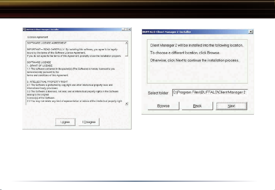
Client Manager
� Once the Installer Wizard launches, click the Next button to begin the
software installation.
� Press I Agree to accept the license agreement and continue the installation
12
Page 13
Client Manager
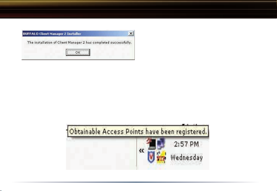
� Press the OK button to finish and
close the installation program.
� Press the Exit button to exit the Client Manager installation utility.
� The Buffalo Client Manager is now installed and running, right clicking on its
icon (the black notebook icon) will allow you to begin using it.
13
Page 14

Client Manager Configuration
Client Manager Configuration
Use Client Manager to configure your wireless network. To assist in configuring
your wireless network, Client Manager consists of the Status page, the Survey
page, and the Profiles page. You can access each page by clicking the corre
sponding button on Client Manager. In addition to these pages, several dialog
boxes are available to meet specialized configuration needs. You can access
the Edit Profile dialog box, New Profile dialog box, IP Configuration dialog box,
or WEP Configuration dialog box using the Client Manager pages.
Status Page
Click the Status button to open this
page. By default, this page is displayed when you start
Client Manager. This page displays
the status of the connection be
tween the wireless adapter and
another wireless device. This page
only displays connection information
no changes to the connection can be
made from this screen.
This page includes the following
components:
-
-
14
Page 15

Client Manager Configuration
• Rate – The speed that the two wireless clients are communicating at. If the
Client Manager is not connected to a remote wireless device (access
another client) then no rate will be displayed.
• Channel – The channel that the two wireless clients are communicating at.
If the Client Manager is not connected to a remote wireless device (a
point of another client) then no channel will be displayed. The available chan
nels for use are 1-11.
• Security– The type of encryption that the two wireless clients are communicat-
ing with. If the Client Manager is not connected to a remote wireless device
(access point of another client) then ‘No Encryption’ will be displayed.
• IP Address – The IP address of the machine the Client Manager is installed on.
If the Client Manager is not connected to a remote wireless device (access
point of another client) or is not connected to a network with DHCP, then no
IP address will be displayed.
• MAC Address – The MAC address of the wireless client device inside the com-
puter Client Manager is installed on. If no wireless device is present in the
computer, then no MAC Address will be displayed.
• Signal Strength – Displays the strength of the signal. Signal Strength is based
on the peak signal level the wireless adapter receives from the wireless device
to which it is connected. Next to the signal level is the wireless hardware type
point or
ccess
-
15
Page 16

Client Manager Configuration
Survey Page
Click the Survey button to open this page. Use this page to survey the area, display available access points, and connect to available access points.
This page includes the following
components:
• Wireless SSID – Displays the SSID associated with each available access
point. The SSID is the unique net
work name that functions as an iden
tifier for your wireless devices. All
wireless devices on a network must
use identical SSIDs to successfully
associate with other devices on the
network. buffalo_test is an example
of a valid SSID.
• Mode – Displays the mode/rate set
that the remote wireless device is
offering.
• Key – Displays whether the wireless network is using any sort of encryption.
-
-
16
Page 17

Client Manager Configuration
Once the ‘Connect’ button is pressed, you will be prompted to enter any encryption related information.
The ‘Acquire IP automatically’ checkbox tells
the client device to obtain an IP automatically from a DHCP server. This is the recommended setting.
Encryption’ drop down list allows you to
The ‘
select the type of encryption for the net
work. By default the proper encryption type
should already be selected. In the event
that no encryption is used, leave the
Encryption’ option selected.
by the wireless network must be inputted. Please consult your wireless access
point or router’s documentation for proper input of the encryption keys. Some
wireless networks may require you to enter multiple keys, in this event, four
separate fields are available for encryption keys.
-
‘No
The ‘Save settings as a profile
files. This means you will automatically connect to this network when inside
’ option will store this wireless network in your pro-
17
Page 18

Client Manager Configuration
Profiles Page
Click the Profiles button to open this
page. Use this page to access your
profiles. Profiles allow you to save
the information associated with a
specific wireless network so you can
quickly and easily connect to that
network when you are in that loca
tion. The Profiles page allows you to
add, delete, and edit your profiles, as
well as import and export data.
• Connect – Click the Connect button to
connect to the selected profile and
return to the ‘Status’ page.
• Edit – Click the Edit button to edit the selected profile’s settings. The Edit button also allows you to delete a profile no longer used or required.
• Add – Click the Add button to add a profile manually. You will need important
information such as SSID, encryption settings, and network type.
-
18
Page 19

Client Manager Configuration
New Profile Dialog Box
Use this dialog box to create a new profile.
• Profile Name – Enter the name you want to associate with the new profile.
• Network Type – Select the network mode you want
to associate with the new profile. Select Infra-
structure if your network consists of both wired
and wireless devices that communicate through
a central device, such as an access point. Select
Ad-hoc if your network consists of only wireless devices that communicate with each other
directly.
• Network Name SSID – Enter the SSID of your net-
must use identical SSIDs to successfully associate with other devices on the
network.
• Channel – Displays the channel associated with the new profile. The channel
indicates what range of frequencies the radio waves emitted by the wireless
device are occupying. Devices that meet 802.11b and 802.11g standards can
use channels 1-11 within the 2.4 GHz spectrum.
• Encryption Type – Displays the types of encryptions available. Once selected,
you will be required to enter the
as well. For the Encryption Key Number, it is recommended to use 1 unless
specified to by an administrator.
myssid is an example of a valid SSID.
Encryption Key Number and the Encryption Key
19
Page 20

Client Manager Configuration
Advanced Profile Options
• Network Tab – Displays the network information tab. A static IP can be specified for this wireless profile here. It is not recommended to change any of
these settings unless specified by an administrator.
• Browser Tab – Displays settings to change your browser preferences for this
wireless profile. A specific home page can be specified when connected to
this wireless profile as can specific proxy server addresses.
• Printers Tab – Displays the printers tab. A specific default printer can be asso-
ciated to this profi
will be used as the default printer.
• Network Tab – Displays the network information tab. A static IP can be specified for this wireless profile here. It is not recommended to change any of
these settings unless specified by an administrator.
• AOSS Icon – The AOSS icon is used to launch AOSS client requests
for AOSS communication. Inside your wireless client’s box, a
AOSS supplement guide is present. This guide leads to step-by-
le. Thus, when connected to this profile, a specific printer
n
20
Page 21

Wireless Zero Configuration
Wireless Zero Configuration Service (Windows XP)
Windows XP offers the Wireless Zero Configuration Service to support 802.11b
and 802.11g wireless networking. This ser vice automatically polls the area for
available wireless access points. If an available wireless access point is found,
Windows attempts to connect to the access point. If no available wireless ac
cess points are found, you must manually add the access points.
n Note: The Wireless Zero Configuration Service and Client Manager do not
function properly together. If you want to use Client Manager, you must disable
the Wireless Zero Configuration Service.
Enabling the Wireless Zero Configuration Service
Select Start»Control Panel»Administrative Tools»Services to open the Services window. Select
Service to enable the Wireless Zero Configuration Service.
n Note: The default Startup Type value of Wireless Zero Configuration Service
is Automatic.
Automatic in the Startup Type field of Wireless Zero Configuration
Disabling the Wireless Zero Configuration Service
Select Start»Control Panel»Administrative Tools»Services to open the Services window. Select Disabled in the Startup Type field of Wireless Zero Configuration
Service to disable the Wireless Zero Configuration Service.
-
21
Page 22

Specifications
Communication Range
Speed Indoor Outdoor
54Mbps 165 ft. (50m) 525 ft. (160m)
11Mbps 300 ft. (90m) 1310 ft. (400m)
1Mbps 375 ft. (115m) 1750 ft. (550m)
All distances are estimated. Wireless connections may be affected as physical conditions and
circumstances vary.
22
Page 23

Troubleshooting / FAQ
Troubleshooting / FAQ
Use this section to locate answers to frequently asked questions.
What should I do if I already have a version of Client Manager on my PC?
Update your Client Manager to the version on the CD. If you do not update
your Client Manager, there could be a loss of functionally, as some versions of
Client Manager will not work properly with the G54 Wireless 54Mbps Desktop
PCI Adapter. Before updating Client Manager, you must uninstall all previous
versions of Client Manager. To update your Client Manager, load the Air
Navigator CD and select Install Client Manager.
Why won't all my network clients work?
Some operating systems support only a limited number of network clients.
Windows 98/Me: These operating systems support only four network clients. If
you install more than four network clients, only the first four clients you install
will work.
Will Client Manager support all operating systems?
Client Manager and the G54 Wireless 54Mbps Desktop PCI Adapter currently
support only Windows 98/ME/2000/XP. They do not currently support Windows
NT, Mac OS, or Linux. For more information, refer to the Mac OS and Linux page
23
Page 24

Troubleshooting / FAQ
Why won't Client Manager function properly?
Windows XP – The Wireless Zero Configuration Service conflicts with Client Manager. Select Start»Control Panel»Administrative Tools»Services to open the Services
window. Select
Service to disable the Wireless Zero Configuration Service.
I have more than one Air Navigator CD. Do I need more than one CD?
No. You receive the same Air Navagator CD with each Buffalo Technology access point and wireless adapter. The CDs are identical and you only need one
copy.
Disabled in the Startup Type field of Wireless Zero Configuration
24
Page 25

Glossary
10BaseT or 100BaseTx: 802.3 based
Ethernet network that uses UTP (Unshielded twisted pair) cable and a star
topology. 10 is 10 Mbps and 100 is
100 Mbps.
802.1x: The standard for wireless LAN
authentication used between an AP
and a client. 802.1x with EAP will ini
tiate key handling.
Ad-Hoc Network: The wireless network
based on a peer-to-peer communications session. Also referred to as
AdHoc.
Bandwidth: The transmission capacity of a computer or a communication
channel, stated in Megabits per sec
ond (Mbps).
BSS (Basic Service Set): An 802.11 networking framework that includes an
Access Point.
Bus Mastering: A system in which the
-
-
specified Input/Output device (e.g. NIC
Card) can perform tasks without the
intervention of the CPU.
Client: A PC or workstation on a network.
Cross-Over Wiring: A UTP cable that has
its transmit and receive pair crossed
to allow communications between two
devices.
DCE (Data Communications Equipment):
Hardware used for communication
with a Data Terminal Equipment (DTE)
device.
Default Gateway: The IP Address of
either the nearest router or server for
the LAN.
Default Parameter: Parameter set by the
manufacturer.
Destination Address: The address por
tion of a packet that identifies the
intended recipient station.
25
-
Page 26

Glossary
DHCP (Dynamic Host Configuration Protocol): Based on BOOTP, it uses a pool of
IP addresses, which it assigns to each
device connected to it, and retrieves
the address when the device becomes
dormant for a period of time.
DNS (Domain Name System): System
used to map readable machine names
into IP addresses
Driver: Software that interfaces a computer with a specific hardware device.
DSSS (Direct Sequence Spread Spectrum):
Method of spreading a wireless signal
into wide frequency bandwidth.
DTE (Data Terminal Equipment): Device
that con
based Ethernet network that uses UTP
(Unshielded twisted pair) cable and a
star topology. 10 is 10 Mbps and 100
is 100 Mbps.
802.1x: The standard for wireless LAN
10BaseT or 100BaseTx: 802.3
authentication used between an AP
and a client. 802.1x with EAP will ini
tiate key handling.
Ad-Hoc Network: The wireless network
based on a peer-to-peer communications session. Also referred to as
AdHoc.
Bandwidth: The transmission capacity of a computer or a communication
channel, stated in Megabits per sec
ond (Mbps).
BSS (Basic Service Set): An 802.11 networking framework that includes an
Access Point.
Bus Mastering: A system in which the
specified Input/Output device (e.g. NIC
Card) can perform tasks without the
intervention of the CPU.
Client: A PC or workstation on a network.
Cross-Over Wiring: A UTP cable that has
26
-
-
Page 27

Glossary
its transmit and receive pair crossed
to allow communications between two
devices.
DCE (Data Communications Equipment):
Hardware used for communication
with a Data Terminal Equipment (DTE)
device.
Default Gateway: The IP Address of
either the nearest router or server for
the LAN.
Default Parameter: Parameter set by the
manufacturer.
Destination Address: The address portion
of a packet that identifies the intended
recipient station.
DHCP (Dynamic Host Configuration Proto
col): Based on BOOTP, it uses a pool of
IP addresses, which it assigns to each
device connected to it, and retrieves
the address when the device becomes
dormant for a period of time.
-
DNS (Domain Name System): System
used to map readable machine names
into IP addresses
Driver: Software that interfaces a computer with a specific hardware device.
DSSS (Direct Sequence Spread Spectrum):
Method of spreading a wireless signal
into wide frequency bandwidth.
DTE (Data Terminal Equipment): Device
that controls data flowing to and from
a computer.
Dynamic IP Address: An IP address that
is automatically assigned to a client
station in a TCP/IP network, typically
by a DHCP server.
ESS (Extended Service Set): A set of two
or more BSSs that form a single subnetwork. ESS-ID is user identification
used in the ESS LAN configuration.
Ethernet: The most widely used ar-
27
Page 28

Glossary
chitecture for Local Area Networks
(LANs). It is a shared-media network
architecture. The IEEE 802.3 standard
details its functionality.
Ethernet cable: A wire similar to telephone cable that carries signals be
tween Ethernet devices.
File and Print Sharing: A Microsoft application that allows computers on a
network to share files and printers.
Firmware: Programming inserted into
programmable read-only memory, thus
becoming a permanent part of a computing device.
Frame: A fixed block of data, transmitted as a single entity. Also referred to
as packet.
Full-Duplex: To transmit on the same
channel in both directions simultane
ously.
Gbps (Giga Bits per second): One billion
-
-
bits per second.
Half-duplex: To transmit on the same
channel in both directions, one direc
tion at a time.
Hub: A device which allows connection of computers and other devices to
form a LAN.
IEEE (Institute of Electrical and Electronics
Engineers): The professional organiza-
tion which promotes development of
electronics technology.
IP (Internet Protocol) Address:
32-binary-digit number that identifies
each sender or receiver of information
sent in packets.
Infrastructure: A wireless network or
other small network in which the wire
less network devices are made a part
of the network through the Access
Point.
28
A unique
-
-
Page 29

Glossary
ISP (Internet Service Provider): A company
that provides access to the Internet
and other related services.
IV (Initialization Vector): The header sec
tion of a message packet.
LAN (Local Area Network): A group of
computers and peripheral devices con
nected to share resources.
LED (Light Emitting Diode): The lights on
a hardware device representing the
activity through the ports.
MAC (Medium Access Control) Address:
unique number that distinguishes network cards.
Mbps (Mega Bits Per Second): A measurement of millions of bits per second.
MDI/X (Media Dependent Interface/Crossover): Port on a network hub or switch
that crosses the incoming transmit
lines with the outgoing receive lines.
-
A
MHz (MegaHertz): One million cycles per
second.
MIB II: A database containing performance information and statistics on
each device in a network.
MIPS (Million Instructions Per Second): A
-
measurement of processing speed.
NAT (Network Address Translation):
internet standard that enables a LAN
to use one set of IP addresses for
internal traffic and a second set for
external traffic.
NIC (Network Interface Card): An expansion card connected to a computer so
the computer can be connected to a
network.
Packet: A block of data that is transferred as a single unit, also called a
frame or a block.
Packet Filtering: Discarding unwanted
29
An
Page 30

Glossary
network traffic based on its originating
address or its type.
PCI (Peripheral Component Interconnect): A
bus that is connected directly to the
CPU.
PCMCIA (Personal Computer Memory Card
International Association) Card: Remov
able module that adds features to a
portable computer.
Ping (Packet Internet Groper): An Internet
utility used to determine whether a
particular IP address is online.
Plug and Play: Hardware that, once
installed (“plugged in”), can immediately be used (“played”), as opposed
to hardware that requires manual
configuration.
PoE (Power over Ethernet): A mechanism
to send DC power to a device using a
CAT5 Ethernet cable.
-
PPPoE (Point-to-Point Protocol over Ethernet): A specification for connect-
ing users on an Ethernet line to the
Internet through a common broadband
medium.
Protocol: A standard way of exchanging information between computers.
RADIUS (Remote Authentication Dial In User
Service): A server that issues authenti-
cation key to clients.
RAM (Random Access Memory):
manent memory.
Repeater Hub: A device that collects,
strengthens and transmits information
to all connected devices, allowing the
network to be extended to accommo
date additional workstations.
RC4: The encryption algorithm that is
used in WEP.
RJ-45 connector: An 8-pin connector
used between a twisted pair cable and
30
Non-per-
-
Page 31

Glossary
a data transmission device.
ROM (Read Only Memory): Permanent
memory.
Router: Device that can connect individual LANs and remote sites to a
server.
Roaming: The ability to use a wireless
device while moving from one access
point to another without losing the
connection.
Script: A macro or batch file containing instructions and used by a computer to perform a task.
Server: Any computer that makes files
or peripheral devices available to users of the network and has a resident
Network OS.
SMTP (Simple Mail Transfer Protocol): The
protocol used to define and deliver
electronic mail (E-mail) from one loca
tion to another.
SNMP (Simple Network Management Proto
col: An application layer protocol that
outlines the formal structure for communication among network devices.
Static IP Address: A permanent IP ad
dress is assigned to a node in a TCP/IP
network. Also known as global IP.
STP (Shielded Twisted Pair): Twisted Pair
cable wrapped in a metal sheath to
provide extra protection from external
interfering signals.
Subnet Mask: An eight-byte address
divided into 4 parts separated by periods.
TCP/IP (Transmission Control Protocol/Inter
net Protocol: Protocol used by comput-
ers when communicating across the
Internet or Intranet.
-
TFTP (Trivial File Transfer Protocol):
31
-
-
-
Sim-
Page 32

Glossary
ple form of FTP (File Transfer Protocol), which Uses UDP (User Datagram Protocol),
rather than TCP/IP for data transport and provides no security features.
TKIP (Temporal Key Integrity Protocol): An encr yption method replacing WEP. TKIP
uses random IV and frequent key exchanges.
Topology: The shape of a LAN (Local Area Network) or other communications sys
tem.
Twisted Pair: Cable that comprises 2 or more pair of insulated wires twisted togeth
er.
UDP (User Datagram Protocol): A communication method (protocol) that offers a
limited amount of service when messages are exchanged between computers in a
network. UDP is used as an alternative to TCP/IP.
Uplink: Link to the next level up in a communication hierarchy.
UTP (Unshielded Twisted Pair) cable: Two or more unshielded wires twisted together to
form a cable.
WAN (Wide Area Network): A networking system covering a wide geographical area.
WEP (Wired Equivalent Privacy): An encryption method based on 64 or 128-bit algo
rithm.
Web Browser: A software program that allows viewing of web pages.
Wi-Fi (Wireless Fidelity): An organization that tests and assures interoperability
-
-
-
32
Page 33

FCC / CE Information
Federal Communication Commission Interference Statement
This equipment has been tested and found to comply with the limits for a Class
B digital device, pursuant to Part 15 of the FCC Rules. These limits are designed
to provide reasonable protection against harmful interference in a residential
installation. This equipment generates, uses and can radiate radio frequency
energy and, if not installed and used in accordance with the instructions, may
cause har mful interference to radio communications. However, there is no
guarantee that interference will not occur in a particular installation. If this
equipment does cause harmful interference to radio or television reception, which
can be determined by turning the equipment off and on, the user is encouraged
to try to correct the interference by one of the following measures:
• Reorient or relocate the receiving antenna.
• Increase the separation between the equipment and receiver.
• Connect the equipment into an outlet on a circuit different from that to
which the receiver is connected.
• Consult the dealer or an experienced radio/TV technician for help.
FCC Caution: To assure continued compliance, (example - use only shielded
interface cables when connecting to computer or peripheral devices). Any changes
or modifications not expressly approved by the par ty responsible for compliance
could void the user’s authority to operate this equipment.
This device complies with Part 15 of the FCC Rules. Operation is subject to the
33
Page 34

FCC / CE Information
(2) this device must accept any interference received, including interference that
may cause undesired operation.
IMPORTANT NOTE:
FCC RF Radiation Exposure Statement:
This equipment complies with FCC RF radiation exposure limits set forth for an
uncontrolled environment. This equipment should be installed and operated with
a minimum distance of 20 centimeters between the radiator and your body.
This transmitter must not be co-located or operating in conjunction with any
other antenna or transmitter.
Europe – EU Declaration of Conformity
This device complies with the essential requirements of the R&TTE Directive 1999/5/EC. The
following test methods have been applied in order to prove presumption of compliance with the
R&TTE Directive 1999/5/EC:
- EN 60950-1: 2001, First Edition
Safety of Information Technology Equipment
- EN 300 328 V1.4.1 (2003-4)
Technical requirements for spread-spectrum radio equipment
34
Page 35

FCC / CE Information
- EN 301 489-1 V1.4.1 (2002-08)
- EN 301 489-17 V1.2.1 (2002-08)
EMC requirements for spread-spectrum radio equipment.
This device is a 2.4 GHz wireless LAN transceiver, intended for home and office use in all EU and
EFTA member states, except in France, Belgium and Italy where restrictive use applies.
In Italy the end-user should apply for a license at the national spectrum authorities in order to
obtain an authorization to use the device for setting up outdoor radio links.
In Belgium there is a restriction in outdoor use. The frequency range in which outdoor operation in
Belgium is permitted is 2460 – 2483.5 MHz.
This device may not be used for setting up outdoor radio links in France. For more information see
http://www.anfr.fr/ and/or http://www.art-telecom.fr
English Hereby, BUFFALO, INC., declares that this Wireless Adapter is in compliance with the
essential requirements and other relevant provisions of Directive 1999/5/EC.
Finnish BUFFALO, INC. vakuuttaa täten että Wireless Adapter tyyppinen laite on direktiivin
1999/5/EY oleellisten vaatimusten ja sitä koskevien direktiivin muiden ehtojen mukainen.
35
Page 36

FCC / CE Information
Dutch Hierbij verklaart BUFFALO, INC. dat het toestel Wireless Adapter in overeenstemming is
met de essentiële eisen en de andere relevante bepalingen van richtlijn 1999/5/EG
Bij deze verklaart BUFFALO, INC. dat deze Wireless Adapter voldoet aan de essentiële
eisen en aan de overige relevante bepalingen van Richtlijn 1999/5/EC.
French Par la présente BUFFALO, INC. déclare que l’appareil Wireless Adapter est conforme
aux exigences essentielles et aux autres dispositions pertinentes de la directive 1999/5/CE
Par la présente, BUFFALO, INC. déclare que ce Wireless Adapter est conforme aux
exigences essentielles et aux autres dispositions de la directive 1999/5/CE qui lui sont applicables
Swedish Härmed intygar BUFFALO, INC. att denna Wireless Adapter står I överensstämmelse
med de väsentliga egenskapskrav och övriga relevanta bestämmelser som framgår av direktiv
1999/5/EG.
Danish Undertegnede BUFFALO, INC. erklærer herved, at følgende udstyr Wireless Adapter
overholder de væsentlige krav og øvrige relevante krav i direktiv 1999/5/EF
German Hiermit erklärt BUFFALO, INC., dass sich dieser/diese/dieses Wireless Adapter
in Übereinstimmung mit den grundlegenden Anforderungen und den anderen relevanten
Vorschriften der Richtlinie 1999/5/EG befindet”. (BMWi)
Hiermit erklärt BUFFALO, INC. die Übereinstimmung des Gerätes Wireless Adapter
mit den grundlegenden Anforderungen und den anderen relevanten Festlegungen der Richtlinie
1999/5/EG. (Wien)
Greek ΜΕ ΤΗΝ ΠΑΡΟΥΣΑ BUFFALO, INC. ΔΗΛΩΝΕΙ ΟΤΙ Wireless Adapter
ΣΥΜΜΟΡΦΩΝΕΤΑΙ ΠΡΟΣ ΤΙΣ ΟΥΣΙΩΔΕΙΣ ΑΠΑΙΤΗΣΕΙΣ ΚΑΙ ΤΙΣ ΛΟΙΠΕΣ ΣΧΕΤΙΚΕΣ ΔΙΑΤΑΞΕΙΣ
36
Page 37

FCC / CE Information
ΤΗΣ ΟΔΗΓΙΑΣ 1999/5/ΕΚ
Italian Con la presente BUFFALO, INC. dichiara che questo Wireless Adapter è conforme ai
requisiti essenziali ed alle altre disposizioni pertinenti stabilite dalla direttiva 1999/5/CE.
Spanish Por medio de la presente (nombre del fabricante) declara que el (clase de equipo)
cumple con los requisitos esenciales y cualesquiera otras disposiciones aplicables o exigibles de
la Directiva 1999/5/CE
Portuguese BUFFALO, INC. declara que este Wireless Adapter está conforme com os
requisitos essenciais e outras disposições da Directiva 1999/5/CE.
Safety
This equipment is designed with the utmost care for the safety of those who install and use it.
However, special attention must be paid to the dangers of electric shock and static electricity
when working with electrical equipment. All guidelines of this manual and of the computer
manufacturer must therefore be allowed at all times to ensure the safe use of the equipment.
EU Countries intended for use
The ETSI version of this device is intended for home and office use in Austria, Belgium, Denmark,
Finland, France (with Frequency channel restrictions), Germany, Greece, Iceland, Ireland, Italy,
Luxembourg, Norway, The Netherlands, Portugal, Spain, Sweden, Switzerland and United
Kingdom.
The ETSI version of this device is also authorized for use in EFTA member states Iceland,
37
Page 38

FCC / CE Information
Important Notice:
This device is a 2.4 GHz wireless LAN trans-
ceiver, intended for indoor home and office
use in all EU and EFTA member states.
Please refer to previous page in the user
manual for further details.
Intended use
This device is a 2.4 GHz wireless LAN transceiver, intended for indoor home and office use in all
EU and EFTA member states.
EU Countries intended for use
This device is intended for indoor Home and office use in the following countries,
Austria, Belgium, Germany, Denmark, Spain, Greece, France, Finland, Italy, Ireland, Luxembourg,
The Netherlands, Portugal, Sweden, United Kingdom, Cyprus, Czech Republic, Estonia, Hungry, Latvia, Lithuania, Malta, Poland, Slovak Republic and Slovenia.
The device is also authorised for use in all EFTA member states Iceland, Liechtenstein, Norway
38
Page 39

FCC / CE Information
and Switzerland.
EU countries not intended for use
None
Potential restrictive use
This device is a 2.4 GHz wireless LAN transceiver, intended for indoor home and office use in all
EU and EFTA member states, except in France, Belgium and Italy where restrictive use applies.
In Italy the end-user should apply for a license at the national spectrum authorities in order to
obtain an authorization to use the device for setting up outdoor radio links.
In Belgium there is a restriction in outdoor use. The frequency range in which outdoor operation in
Belgium is permitted is 2460 – 2483.5 MHz.
This device may not be used for setting up outdoor radio links in France. For more information see
http://www.anfr.fr/ and/or http://www.art-telecom.fr
39
Page 40

Warranty Information
Buffalo Technology (USA), Inc. products comes with a two-year limited warranty
from the date of purchase. Buffalo Technology (USA), Inc. warrants to the original
purchaser the product; good operating condition for the warranty period. This war
ranty does not include non-Buffalo Technology (USA), Inc. installed components.
If the Buffalo product malfunctions during the warranty period, Buffalo Technol
ogy (USA) Inc. will, replace the unit, provided the unit has not been subjected
to misuse, abuse, or non-Buffalo Technology (USA), Inc. authorized alteration,
modifications or repair.
All expressed and implied warranties for the Buffalo Technology (USA) Inc. product
line including, but not limited to, the warranties of merchantability and fitness of
a particular purpose are limited in duration to the above period.
Under no circumstances shall Buffalo Technology (USA), Inc. be liable in any way
to the user for damages, including any lost profits, lost savings or other incidental
or consequential damages arising out of the use of, or inability to use the Buffalo
products.
In no event shall Buffalo Technology (USA), Inc. liability exceed the price paid for
the product from direct, indirect, special, incidental, or consequential damages
resulting from the use of the product, its accompanying software, or its documen
-
-
-
40
Page 41

Contact Information
ADDRESS
Buffalo Technology (USA), Inc.
4030 West Braker Lane, Suite 120
Austin, TX 78759-5319
GENERAL INQUIRIES
Monday through Friday
8:30am-5:30pm CST
Direct: 512-794-8533
Toll-free:
Fax: 512-794-8520
Email: sales@buffalotech.com
TECHNICAL SUPPORT
North American Technical Support by phone is available 24 hours a day, 7
days a week. (USA and Canada).
Toll-free:
Email: info@buffalotech.com
800-456-9799
(866) 752-6210
41
Page 42

4030 W. Braker Ln. Suite
120
Austin, Texas 78759
Tel: 800-456-9799
Technical Support is available 24 hours a day, 7 days a week
(USA / Canada)
Toll-Free: 866-752-6210
email: info@buffalotech.com
©2004, Buffalo Technology (USA), Inc.
42
 Loading...