

Page 1
User Manual
Antennas
www.buffalotech.com/wireless
Page 2

Table of Contents
Terminology ........................................................................3
Basic Antenna Info ............................................................4
Connecting the Antenna ....................................................5
Accessories............................................................................8
WLE-KG-VPA ........................................................................9
WLE-KG-VPB ........................................................................9
WLE-NDR ............................................................................10
WLE-DA2 ............................................................................11
WLE-HG-NDR ......................................................................12
WLE-MYG ..........................................................................13
WLE-HG-NDC ......................................................................14
WLE-HG-DYG......................................................................16
Technical Support ..............................................................18
Warranty ............................................................................19
FCC Compliance..................................................................20
2
Page 3

Terminology
Directional Antenna - Is an antenna that radiates a signal in
one direction using a tight beam pattern. These
antennas come in several styles; yagi, panel and
parabolic.
db (decibel) - A unit of measurement for Antenna strength.
The higher the db rating the higher the strength of
the antenna.
Cable Loss - The loss in signal strength (db) due to the length
of your antenna cable. The longer the cable, the
greater the signal loss.
Fresnel Zone - An elliptical area on either side of the straight
line of sight that must also be clear for a long-range
wireless signal to work.
Gain - Amount of wireless signal strength added to a
standard signal normally measured in db ’s.
MC Card Connector - Antenna connector type used on Buffalo
Technology routers/AP’s, adapter and indoor antenna
products.
N type connector - Antenna connector type used on Buffalo
Technology outdoor antenna’s and coaxial cable.
Omni-Directional Antenna - An Antenna that radiates a signal
in a 360 degree radius horizontally and a signal
vertically with a degree spread that is dependent on
the antenna’s elements.
3
Page 4
Basic Antenna Information
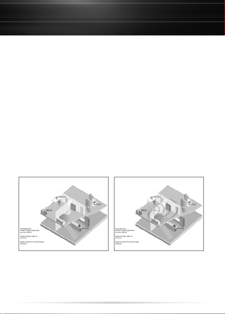
Wireless signals travel outward in an arc pattern from the
source. These radio frequencies lose significant signal strength
when traveling through walls, windows and other objects.
Materials like metal, stucco and thick concrete can actually
stop a wireless signal from passing through. Sometimes these
obstacles can be overcome by adding an antenna to your
wireless network.
Another issue is distance as the signal spreads outward from
the source it becomes dispersed and looses signal strength
and bandwidth. This is where an antenna helps the most in
increasing the overall signal and carrying it farther. An
average 8 dbi outdoor antenna can carry your signal up to 3/4
of a mile. Different Antennas have different signal patterns.
Signal range without external antenna Signal range with external antenna
4
Page 5
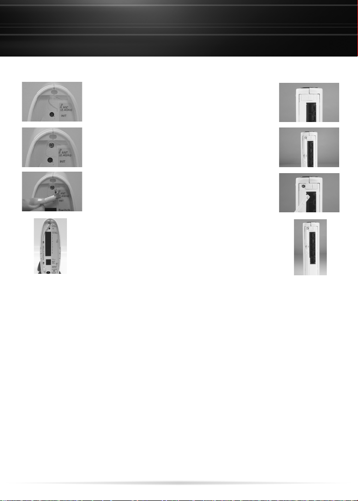
Connecting the Antenna
AirStation Routers/Access Points
Large Form Factor Access Points / Routers
Locate the antenna connector sliding door on the
❶
rear of the AirStation.
Slide the door down on the rear of the AirStation to
❷
reveal the external antenna connector.
Note: On some AP's the door slides sideways.
Connect the antenna to the AirStation by plugging
❸
the male MC Card connector on the antenna cable
to the female MC Card connector on the AirStation.
Push firmly into place to ensure a good connection.
Run the cable down the left side of the AirStation
❹
and push behind the plastic tab to keep the antenna
from coming loose.
5
Page 6
Connecting the Antenna
Access Points/Client Adapters
Small Form Factor Access Points / Client Adapters
Locate the rubber antenna connector plug on the rear of the
❶
AirStation.
Remove the Rubber plug on the rear of the AirStation to reveal the
❷
external antenna connector.
Note: On some AP's the door slides sideways.
Connect the antenna to the AirStation by plugging the male MC
❸
Card connector on the antenna cable to the female MC Card
connector on the AirStation. Push firmly into place to ensure a good
connection.
Run the cable down the back of the AirStation.
❹
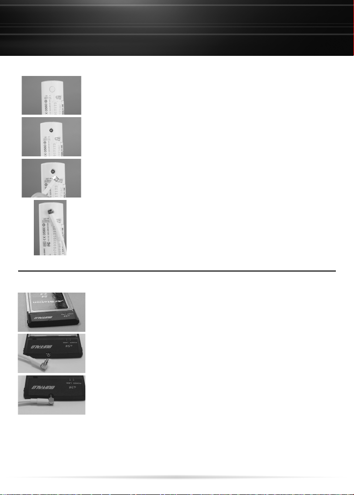
PCMCIA Client Adapters
Locate the rubber plug hiding the external MC Card antenna
❶
connector on the top of the AirStation Notebook Adapter.
Pull the rubber plug to reveal the external antenna connector
❷
Connect the antenna to the Notebook Adapter by plugging the male
❸
MC Card connector on the antenna cable to the female MC Card
connector on the Notebook Adapter. Push firmly into place to
ensure a good connection.
NOTE: Client Cards with external antenna support vary but
installation remains the same.
6
Page 7

PCI Client Adapter
Connecting the Antenna
Disconnect the rubber antenna from card.
❶
Find the conversion coupler included with the card.
❷
Attach the coupler to the card.
❸
Connect the antenna to the card.
❹
Client Adapter
7
Page 8

Connecting the Antenna
WLE-HG-NDR / WLE-HG-NDC
To install the WLE-HG-DYG and the WLE-HG-NDC you
first slide the rubber boot provided over the coaxial
cable and then connect the coaxial cable to the
antenna as shown below.
You then use the included vinyl tape and wrap the
connection with it. See picture.
Next wrap the vinyl taped connection with the
electrical tape provided. These steps are to help ensure
the connection stays stable and provide water
proofing. Important thing to remember is to start
tapping from the bottom up so that each layer is
overlapping this will help keep water out of the
connection see image.
After you have wrapped the connection you slide the
boot from the previous step over the taping. It should
fit flush against the bottom of the connection base.
8
Page 9

Connecting the Antenna
WLE-HG-NDR / WLE-HG-NDC
Now connect the N-male to MC-card pigtail adapter to
the other end of the cable, as shown.
Now connect the MC-Card connector to your Buffalo
product.
If you are connecting this antenna outside a building
or enclosure and high on a pole you should include a
Lightning protector like the one shown below. Which
can be obtained from third party sources.
This device will connect between the antenna and the
coaxial cable you will then proceed with the other
steps as listed.
9
Page 10

Antenna Mounting Brackets
WLE-KG-VPA / WLE-KG-VPB
When mounting an external antenna it is important to pay attention to the location you are
installing it. Please be aware that small incremental changes in elevation either up, down or side
to side can make significant changes in the signal quality. Several adjustments may be required
to achieve the best signal. You should test mount all antennas to check their signal patterns
before making their mounting permanent.
WLE-KG-VPA
WLE-KG-VPB
10
Page 11

Technical Specifications
Polarization Method Vertical Polarizations
Connector Type MC
Frequency Range 2,401 - 2,484 MHz (1-11channel)
VSWR 1.5 or less with coaxial cable
Antenna Gain Total gain 2.5 dbi or more, without the cable
loss
Range Goal Increase in LOS 20%or more,
Dimensions 164 X 73 X 65 mm
Weight 110 g
Package Contents AirStation Omni Antenna, Mounting Screws,
Antenna Range/Pattern
WLE-NDR
50% or more using both sides
Reference Card, Warranty Card, Manual
Connect the antenna’s MC card connector into the wireless device. Then adjust the antenna to
send/receive the best signal. When using the antenna on an adapter you can judge the signal
strength by watching the bars on the client manager as you adjust the antenna. When used on a
router/AP you can test it by placing a device with a wireless adapter at a low signal position and
then move the antenna on the router/AP to see if the signal improves.
11
Page 12

WLE-DA2
Technical Specifications
Polarization Method Vertical Polarizations
Connector Type MC
Frequency Range 2,401 - 2,484 MHz (1-11channel)
VSWR 1.5 or less with coaxial cable
Antenna Gain Total gain 4 dbi or more, including the cable loss
Range Goal Unobstructed =200% (400% or more using
Dimensions 100 X 100 X 17 mm
Weight 0.3 g
Package Contents AirStation FlatBed Antenna, Mounting Screws,
Connect the antenna’s MC card connector into the wireless device. Then adjust the antenna
to send/receive the best signal. When using the antenna on an adapter you can judge the
signal strength by watching the bars on the client manager as you adjust the antenna. When
used on a router/AP you can test it by placing a device with a wireless adapter at a low signal
position and then move the antenna on the router/AP to see if the signal improves.
Approximate Range
flatbed antennas on both sides)
RP-TNC to MC card adapter, Reference Card,
Warranty card, Manual
12
Page 13

Technical Specifications
WLE-HG-NDR
Polarization Method Vertical or Horizontal; Horizontal during
Connector Type MC, external MC to RP-TNC connector included
Frequency Range 2,401 - 2,484 MHz (1-11channel)
Antenna Gain 6.5 dBi (4.7 dBi including cable loss)
Dimensions 35 X 10.5 X 10 cm
Weight 0.22 kg ,0.45 lb.
Package Contents 2.4 GHz Indoor Omni Antenna with 5 foot cable,
Connect the antenna’s MC card connector into the wireless device. Then adjust the antenna to
send/receive the best signal. When using the antenna on an adapter you can judge the signal
strength by watching the bars on the client manager as you adjust the antenna. When used on a
router/AP you can test it by placing a device with a wireless adapter at a low signal position and
then move the antenna on the router/AP to see if the signal improves.
transmission
2 Screws for wall mounting, MC to RP-TNC
connector, Quick Setup Guide, Warranty
Statement
Approximate Range
The AirStation 6.5 dBi High Gain Indoor Omni Directional
Antenna, model WLE-HG-NDR supports 2.4 GHz 802.11g
and 802.11b wireless devices to increase signal strength up
to 2 times and boost wireless performance. MC to RP-TNC
connector adapter is included for use with other
manufacturers’ wireless devices. The 5 ft.cable offers the
option for desktop placement or wall mounting. Slick
design, easy installation offers a perfect high gain
antenna solution for any wireless network.
Adjustment of antenna angle is
recommended to improve the signal
strength and boost performance.
13
Page 14

Technical Specifications
WLE-MYG
Polarization Method Vertical or Horizontal; Horizontal during
Connector Type MC,external MC to RP-TNC connector included
Frequency Range 2,401 - 2,484 MHz (1-11 Channels)
Antenna Gain 4.5 dBi including cable loss
Weight 0.77 kg
Dimensions 11.6 x 3.6 x 8.1 cm
Package Contents WLE-MYG Antenna, MC to RP-TNC Connector
Connect the antenna’s MC card connector into the wireless device. Then adjust the antenna to
send/receive the best signal. When using the antenna on an adapter you can judge the signal
strength by watching the bars on the client manager as you adjust the antenna. When used on a
router/AP you can test it by placing a device with a wireless adapter at a low signal position and
then move the antenna on the router/AP to see if the signal improves.
The AirStation 5.4 dBi Compact Indoor Directional
Antenna, model WLE-MYG supports 2.4 GHz 802.11g and
802.11b wireless devices to increase signal strength up to
2 times and boost wireless performance. An MC to RPTNC connector adapter is included for use with other
manufacturers’ wireless devices. Compact size offers the
flexibility for laptop placement. Adjustable antenna face
angle provides ease of installation and use. WLE-MYG is
a perfect compact antenna solution for any wireless
network environment.
transmission
Adapter with attached cable, Two Screws,
Quick Setup Guide, Warranty Statement
14
Page 15

WLE-HG-NDC
Technical Specifications
Antenna Type Omni
Polarization Method Vertical Polarity
Polarity, Vertical 15 ± 5° Half value angle
Polarity, Horizontal 32 ± 5° Half value angle
Connector Type N-type Female coaxial connector
Frequency Range 2401 - 2484 MHz (1~11channel)
VSWR 1.5 or less (with co-axial cable)
Antenna Gain 7 dBi or more (antenna only)
Max Input Power 10 W
Wind Resistance 60 m/s or more
Water Proof Class 3 water proof
Life 8 years
Installation Method Pole Mount (Pole not included)
Mounting Pole Diameter ø25~48.6 mm
Operation Environment Temp -30-75°C
Humidity 20-95%
Pressure 800-1060 hPa
Package Contents AirStation Omni Antenna, Antenna pigtail,
Mounting Brackets, Electrical Tape, Vinyl Tape,
Rubber Boot, Warranty card, Manual
Directivity Pattern Diagrams
Vertical directivity pattern Horizontal directivity pattern
15
Page 16

WLE-HG-DYG
Technical Specifications
Polarization Method Flat Diversity Antenna (uni-directional)
Polarization Method Vertical Polarity
Polarity, Vertical 32 ± 5° Half value angle
Polarity, Horizontal 32 ± 5° Half value angle
Connector Type N-type Female coaxial connector
Frequency Range 2401 - 2484 M Hz (1~11channel)
VSWR 1.5 or less (with co-axial cable)
Antenna Gain 14 dBi or more (antenna only)
Max Input Power 10 W
Wind Resistance 60 m/s or more
Water Proof Class 3 water proof
Life 8 years
Installation Method Pole Mount (pole not included)
Mounting Pole Diameter ø25~48.6 mm
Operation Environment Temp -30-75°C
Humidity 20-95%
Pressure 800-1060 hPa
Package Contents AirStation Outdoor Directional Antenna,
Antenna pigtail, Mounting Brackets,
Electrical Tape, Vinyl Tape, Rubber Boot,
Warranty card, Manual
Directivity Pattern Diagrams
Vertical directivity pattern Horizontal directivity pattern
16
Page 17

WLE-CC5
WLE-LNC
WLE-KG-VPA
Accessories
Coaxial Cable for Wireless Lan Outdoor Antenna.
This is a LMR400 coaxial cable with 2 N male connectors.It comes in
3 lengths 5m,10m and 20m.
Pigtail Adapter for Outdoor Antennas Connection
The pigtail connector converts the Airstation ’s MC Card connector
to an N-Type Coaxial connector for use with outdoor antenna
cables and outdoor antennas.
Outdoor mounting bracket for the WLE-HG-NDC and WLE-HG-DYG.
Please see page XX for installation tips.
WLE-KG-VPB
Outdoor mounting bracket for the WLE-HG-NDC and WLE-HG-DYG.
Please see page 10 for installation tips.
17
Page 18

Technical Support
Buffalo Technology offers toll-free technical support 24 hours a day, 7
days a week for this product. Customers in the United States and Canada
can obtain technical support using the following information:
◗ Web www.buffalotech.com/wireless
◗ E-mail help@buffalotech.com (Retail Channel Customers)
info@buffalotech.com (All other Customers)
◗ Telephone 866-752-6210 (USA &Canada only)
The constantly evolving state of wireless products and operating systems
requires Buffalo Technology to occasionally release updated software to
take advantage of new technologies and to comply with industry
standards. For the most recent software, firmware, driver,and technical
white paper releases available,please visit the Buffalo Technology website.
18
Page 19

Warranty
Buffalo Technology (USA), Inc. products comes with a two-year limited
warranty from the date of purchase. Buffalo Technology (USA), Inc.
warrants to the original purchaser the product; good operating condition
for the warranty period. This warranty does not include non-Buffalo
Technology (USA), Inc. installed components. If the Buffalo product
malfunctions during the warranty period, Buffalo Technology (USA) Inc.
will replace the unit, provided the unit has not been subjected to misuse,
abuse, or non-Buffalo Technology (USA), Inc. authorized alteration,
modifications or repair.
All expressed and implied warranties for the Buffalo Technology (USA)
Inc. product line including, but not limited to, the warranties of
merchantability and fitness of a particular purpose are limited in duration
to the above period.
Under no circumstances shall Buffalo Technology (USA), Inc. be liable in
any way to the user for damages, including any lost profits, lost savings or
other incidental or consequential damages arising out of the use of, or
inability to use the Buffalo products.
In no event shall Buffalo Technology (USA), Inc. liability exceed the price
paid for the product from direct, indirect, special, incidental, or
consequential damages resulting from the use of the product, its
accompanying software, or its documentation. Buffalo Technology (USA),
Inc. does not offer refunds for any product.
©2004 Buffalo Technology (USA)Inc.
19
Page 20

FCC
FCC Compliance Statement - This device complies with Part 15 of the FCC
Rules. Operation is subject to the following two conditions: (1)This device
may not cause harmful interference, and (2) this device must accept any
interference received,including interference that may cause undesired
operation.
R&TTE Compliance Statement - This equipment complies with all the
requirements of the DIRECTIVE 1999/5/EC OF THE EUROPEAN
PARLIAMENT AND THE COUNCIL of 9 March 1999 on radio equipment
and telecommunication terminal equipment and the mutual recognition
of their conformity (R&TTE). See the user manual for the complete
statement.
20
 Loading...