

Page 1
AirStation
WHR-300HP2 User Manual
www.buffalotech.com
35020025-01
Page 2

Contents
Chapter 1 - Product Overview ..........................................6
Package Contents .................................................................................6
Diagrams and Layout
Front Panel ......................................................................................................6
Back Panel
Bottom
.......................................................................................................8
.............................................................................................................9
...........................................................................6
Chapter 2 - Installation ....................................................10
Initial Setup ........................................................................................10
Chapter 3 - Configuration ...............................................12
Accessing Settings .............................................................................12
Setup
...................................................................................................14
WAN / LAN
Internet ..........................................................................................................15
PPPoE
DDNS
PPTP Server
.................................................................................................................19
LAN
DHCP
.................................................................................................................20
NAT
Routing
...........................................................................................15
.............................................................................................................16
..............................................................................................................17
...................................................................................................18
..............................................................................................................20
..........................................................................................................21
Wireless ...............................................................................................22
2
Page 3

WPS ................................................................................................................22
AOSS...............................................................................................................23
Basic
Advanced
WMM
MAC Filter
WDS
Multicast Control
...............................................................................................................24
.......................................................................................................26
..............................................................................................................27
......................................................................................................28
................................................................................................................29
..........................................................................................29
Firewall ................................................................................................30
Firewall ..........................................................................................................30
IP Filter
VPN Passthrough
...........................................................................................................31
..........................................................................................32
Games / Apps ......................................................................................33
Port Forwarding ............................................................................................33
DMZ
UPnP
QoS
................................................................................................................34
...............................................................................................................34
.................................................................................................................35
Admin ..................................................................................................36
Name ..............................................................................................................36
Password........................................................................................................36
Time and Date
.................................................................................................................37
NTP
..................................................................................................................38
eco
Access
Syslog Settings
Save/Restore
.............................................................................................................39
...............................................................................................37
..............................................................................................40
.................................................................................................40
Initialize/Restart
Update
...........................................................................................................41
...........................................................................................41
3
Page 4

Diagnostic ...........................................................................................42
System Info ....................................................................................................42
Logs
Packet Info
Client Monitor
Ping
................................................................................................................43
.....................................................................................................43
...............................................................................................44
................................................................................................................44
Chapter 4 - Connect to a Wireless Network ...................45
Automatic Secure Setup (AOSS / WPS) .............................................45
Windows 8, Windows 7 or Windows Vista (Client Manager V) ...................46
Windows XP (Client Manager 3)
Mac OS (AOSS Assistant)
Other Devices (e.g. Game Console)
..............................................................................47
Manual Setup .....................................................................................49
...................................................................47
.............................................................48
Windows 8 (WLAN AutoConfig) ...................................................................49
Windows 7 (WLAN AutoConfig)
Windows Vista (WLAN AutoConfig)
Windows XP (Wireless Zero Configuration)
Mac OS (Wi-Fi)
...............................................................................................55
...................................................................50
.............................................................51
................................................53
Chapter 5 - Troubleshooting ...........................................56
Cannot Connect to the Internet Over a Wired Connection. ............56
Cannot Access Settings.
Cannot Connect to the Network Wirelessly.
Forgot AirStation’s SSID, Encryption Key, or Password.
.....................................................................56
.....................................57
..................57
How to Configure TCP/IP
...................................................................58
4
Page 5

Windows 8 .....................................................................................................58
Windows 7
Windows Vista
Windows XP
Mac OS
.....................................................................................................59
...............................................................................................60
...................................................................................................61
...........................................................................................................61
Other Tips ...........................................................................................62
Chapter 6 - Default Configuration Settings ...................64
Appendix A - Supplemental Information
Technical Specifications ....................................................................68
Environmental Information
..............................................................69
......................68
GPL Information
.................................................................................69
5
Page 6

Chapter 1 - Product Overview
Package Contents
The following items are included in your AirStation package. If any of the items are missing, please contact your vender.
AirStation.................................................1
AirStation Setup Card..........................1
AC adapter...............................................1
Ethernet Cable........................................1
Quick Setup Guide................................1
Warranty Statement.............................1
Diagrams and Layout
Front Panel
1 AOSS Button
To initiate AOSS, hold down this button until the wireless LED flashes (about 3 seconds). Then, push or click the
AOSS button on your wireless client device to complete the connection. Both devices must be powered on for this
to work.
6
Page 7

2 Power / Diag LED (Green or Red)
On (Green):
Power is on.
Blinking (Green):
Booting.
Off:
Power is off.
2 blinks (Red)**:
Flash ROM error.
3 blinks (Red)**:
Wired LAN error.
4 blinks (Red)**:
Wireless LAN error.
5 blinks (Red)***:
IP address setting error.
Continuously blinking*:
Updating firmware, saving settings or initializing settings.
* Do not unplug the AC adapter while the LED is blinking continuously.
** Turn off AirStation first, wait for a few seconds, then turn it back on.
*** Cannot communicate because WAN-side and LAN-side IP addresses are same. Change LAN-side IP address of the
AirStation.
3 Wireless LED (Green or Amber)
On:
Wireless LAN is enabled or transmitting.
Double blinks:
AirStation is waiting for an AOSS or WPS security key.
Continuously blinking:
AOSS/WPS error; failed to exchange security keys.
Off:
Wireless LAN is disabled.
Note: The wireless LED will be green if security is enabled or amber if it is disabled.
4 Internet Access LED (Green)
On:
Router functionality is enabled and you can connect to the Internet.
Blinking:
Router functionality is enabled but you cannot connect to the Internet.
Off:
Router functionality is disabled (the AirStation is in the bridge mode).
5 Router LED (Green or Amber)
On (Green):
Mode switch is in the “Router” position.
On (Amber):
Mode switch is in the “Auto” position.
Off:
Mode switch is in the “Bridge” position.
7
Page 8

Back Panel
1 Mode Switch
This switch changes between router mode and bridge (access point) mode. Auto mode will enable or disable
router functionality automatically.
2 LAN Port
Connect your computer, hub, or other Ethernet devices to these ports. This switching hub supports 10 Mbps and
100 Mbps connections.
3 Internet Port
10 Mbps and 100 Mbps connections are supported.
Note: In bridge (access point) mode, the Internet port becomes a regular LAN port, for a total of 5 usable LAN ports.
4 Reset Button
To reset all settings, hold down this button until the power/diag LED turns red (about 3 seconds). The power must
be on for this to work.
5 DC Connector
Connect the included AC adapter here.
8
Page 9
Bottom
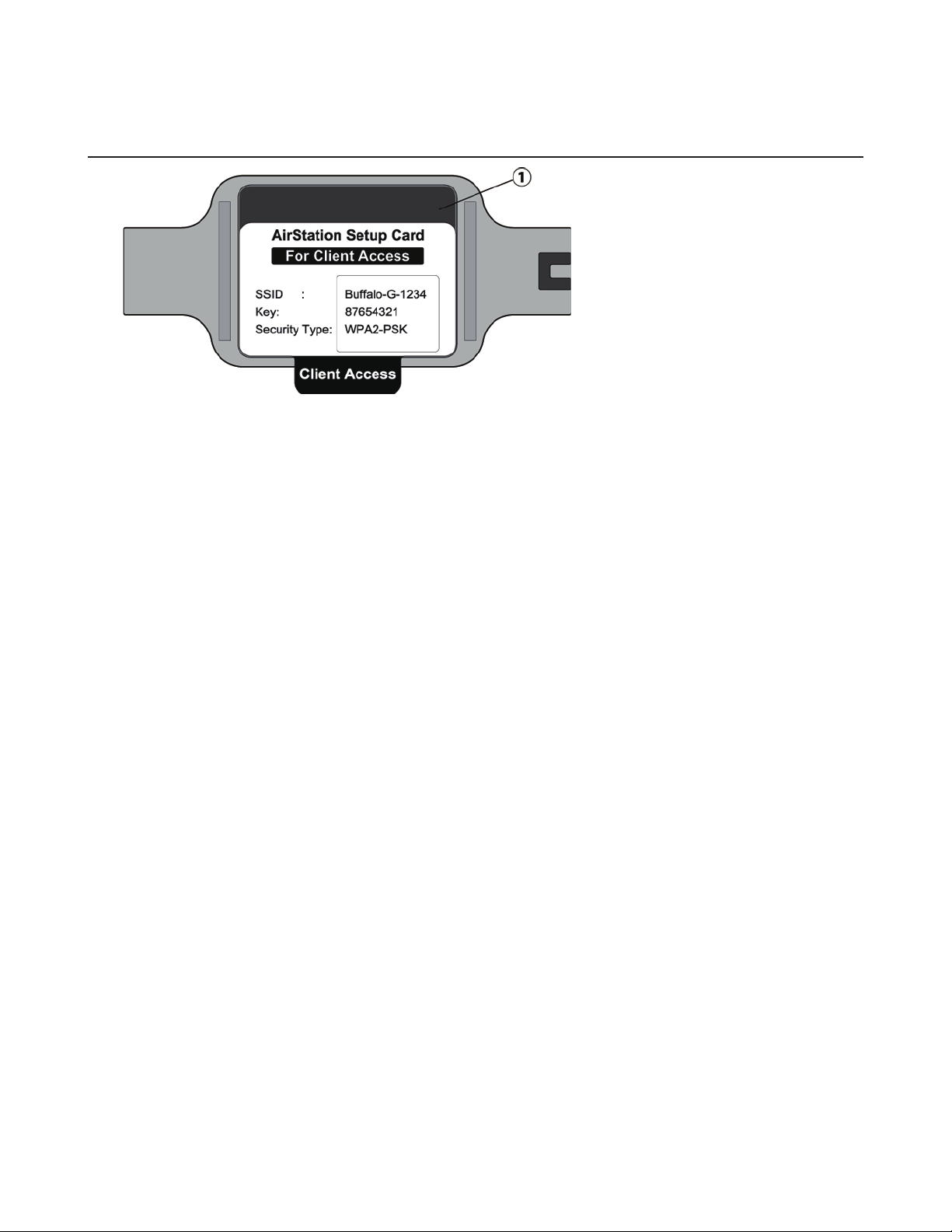
1 Setup Card Slot
This is the slot where the AirStation setup card is stored. The initial settings for the username, password, SSID, and
encryption type are provided on the card.
9
Page 10
Chapter 2 - Installation
Initial Setup
To configure your AirStation, follow the procedure below.
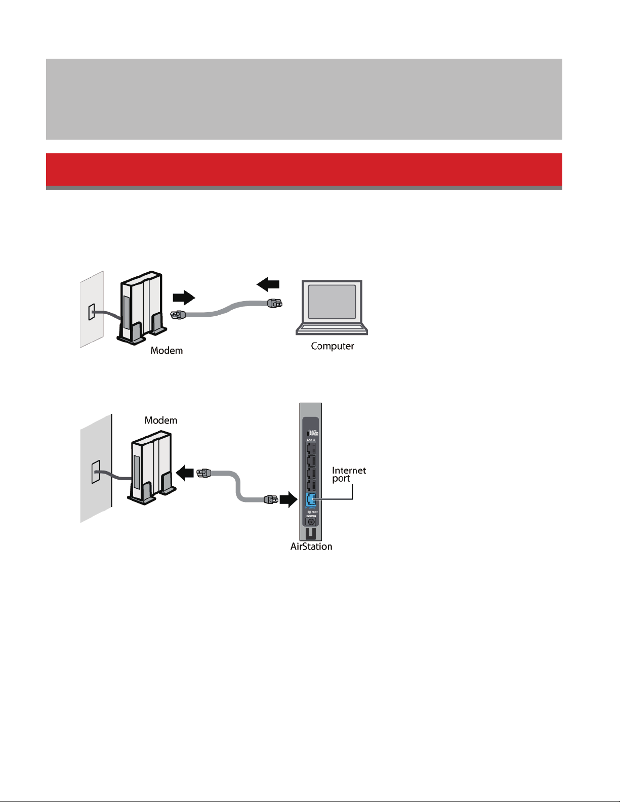
1 Verify that you can connect to the Internet without the AirStation, then turn off your modem and computer.
2 Unplug the LAN cable which connects your computer and modem.
3 Confirm that the mode switch is in the “Auto” position. Plug one end of the LAN cable into your modem and the
other end to the AirStation’s Internet (WAN) port. Turn on the modem.
10
Page 11
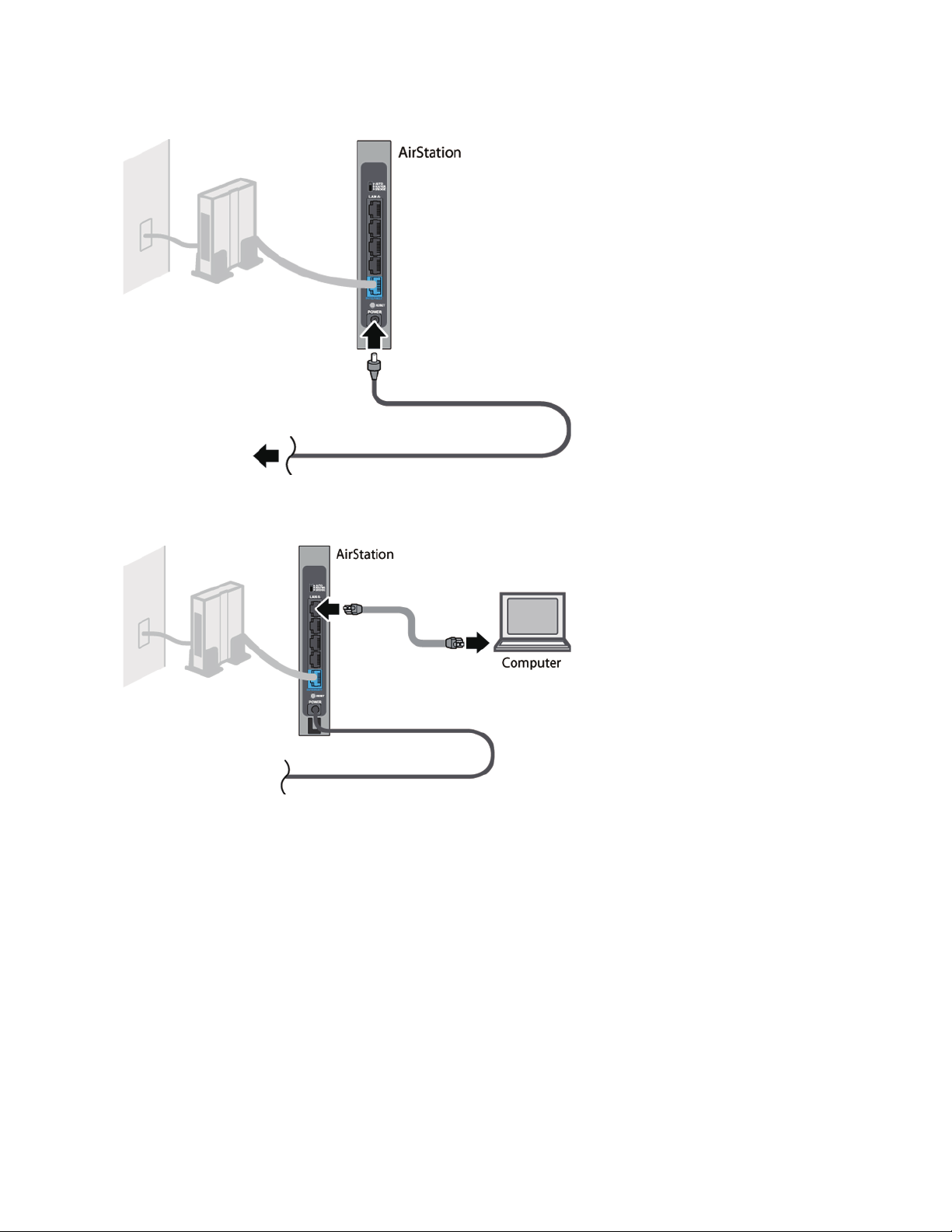
4 Turn on the AirStation and wait one minute.
5 If using a wired LAN, connect the AirStation LAN port and computer using a LAN cable.
If using a wireless LAN, connect the computer to the wireless LAN as described in Chapter 4.
6 Once your computer has booted, the AirStation’s LEDs should be lit as described below:
Power/Diag: Green LED on.
Wireless: Green LED on.
Router: Amber LED on.
For LED locations, refer to chapter 1.
Note: If the router LED is not lit, set the mode switch to “Router”.
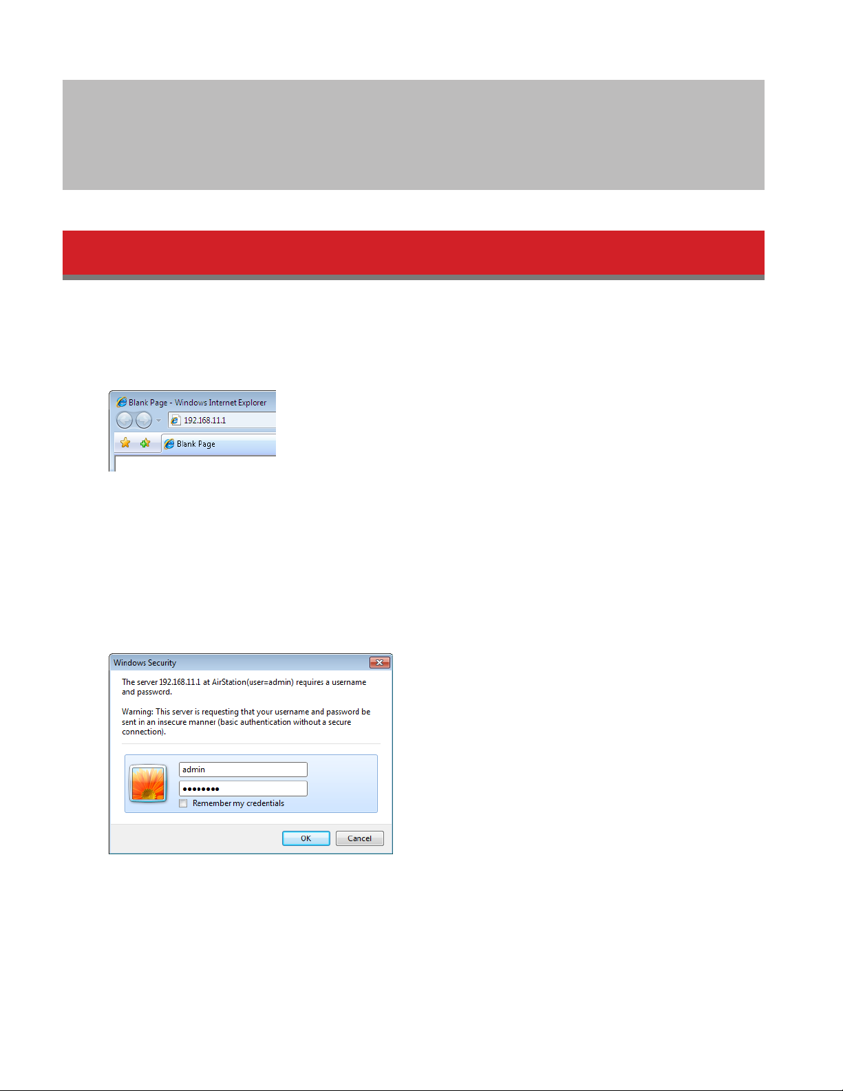
7 Launch a web browser. If the home screen is displayed, setup is complete.
If username and password fields are displayed, enter “admin” for the username and “password” for the password,
then click OK . Step through the wizard to complete setup.
You’ve completed the initial setup of your AirStation. Refer to Chapter 3 for advanced settings.
11
Page 12
Chapter 3 - Configuration
Configuration of the AirStation is done from Settings, the web-based configuration GUI.
Accessing Settings
To configure the AirStation’s settings manually, log in to Settings as shown below.
1 Open a browser.
2 Enter the AirStation’s LAN-side IP address in the address field and press the enter key.
Notes:
• The AirStation’s default LAN-side IP address depends on the mode.
In router mode: 192.168.11.1
In bridge (access point) mode: 192.168.11.100
If the mode switch is set to Auto and the AirStation is in bridge (access point) mode, the AirStation’s IP address is
assigned by an external DHCP server.
• If you changed the IP address of the AirStation, then use the new IP address.
3 Enter “admin” for the username and “password” for the password, then click OK.
Note: If you forget your password, hold down the reset button to initialize all settings. Note that all other settings
will also revert to their default values.
12
Page 13
4 This is Settings , where most AirStation settings can be configured. Help is always displayed on the right side of
each screen. Refer to the help screens for more information on using Settings .
13
Page 14
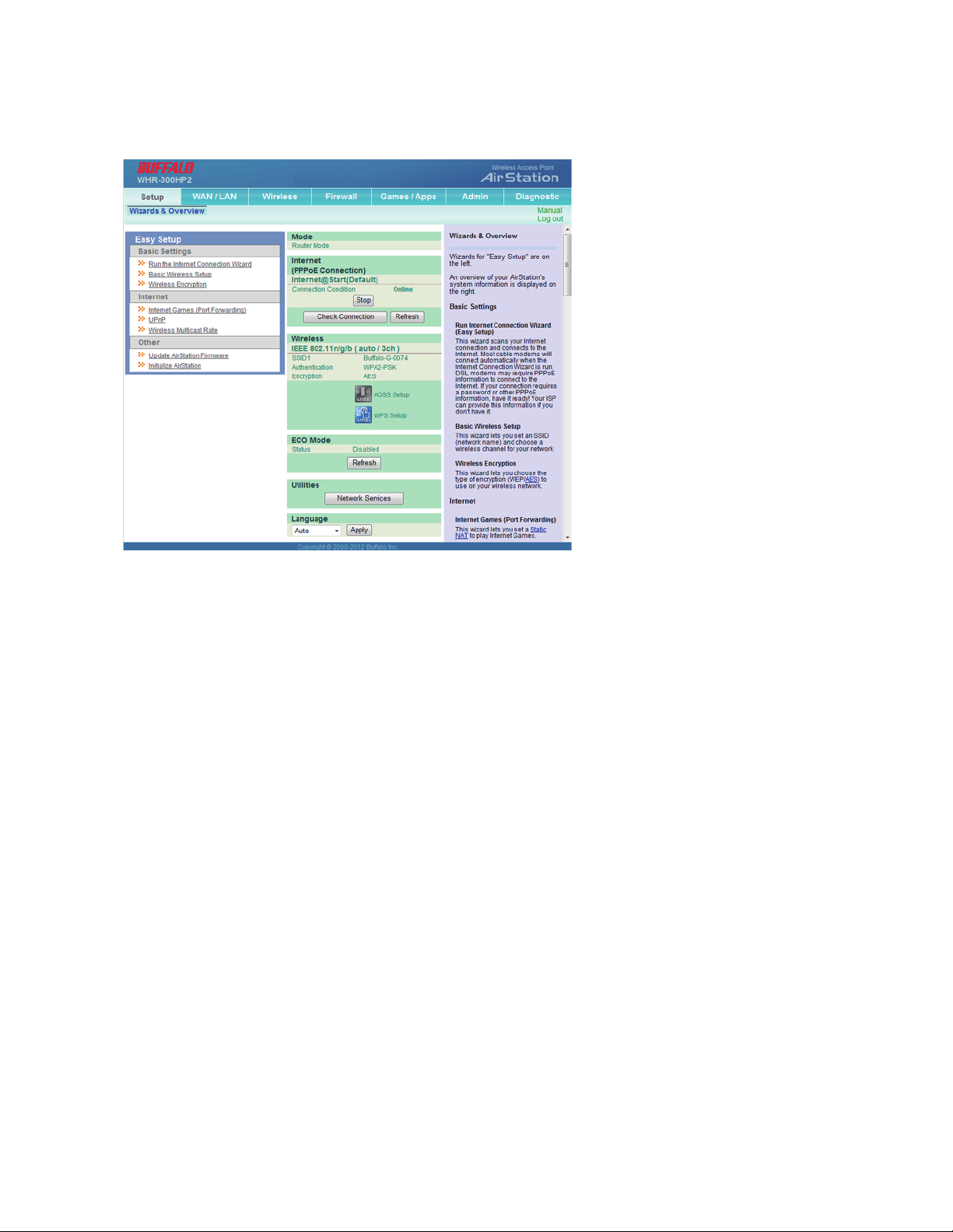
Setup
Setup is the home page of Settings . You can verify settings and the status of the AirStation here.
WAN / LAN Displays the configuration screen for the Internet port and LAN ports.
Wireless Displays the configuration screen for wireless settings.
Firewall Displays the configuration screen for the firewall.
Games / Apps Displays the configuration screen to open ports for games and applications.
Admin Displays the configuration screen for administration settings.
Diagnostic Displays the status of the AirStation.
Easy Setup Enables you to easily configure the AirStation’s network settings automatically.
Mode This indicates the operation mode of the AirStation.
Internet Displays WAN-side system information for the AirStation.
Check Connection Click to check if the AirStation is connected to the Internet properly.
Status Click to refresh the current screen.
Wireless Displays the current wireless settings.
AOSS Setup Click to display the AOSS configuration screen.
WPS Setup Click to display the WPS configuration screen.
eco Mode This indicates the operating status of eco Mode.
Network Services
Displays the list of the network devices for which information is provided from the
network on the LAN-side.
Language Enables you to select the language you use.
Log Out
Log out of Settings . If the AirStation does not communicate for 5 minutes, it will log out
automatically.
14
Page 15
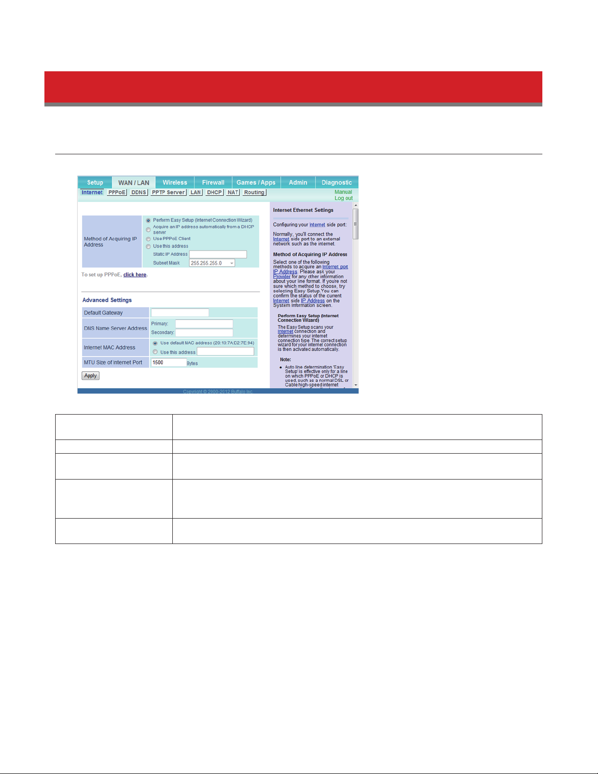
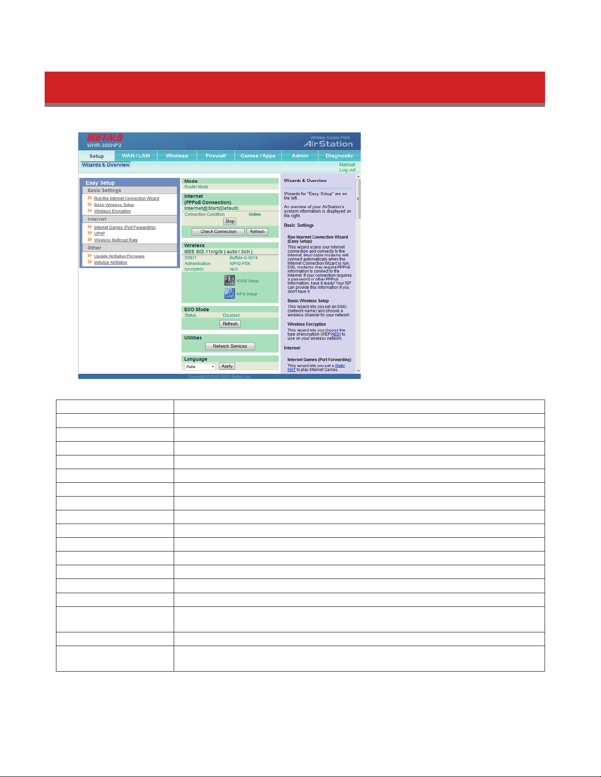
WAN / LAN
Internet
Configure the WAN-side port (“Internet port”) here. This function is only available when the AirStation is in router mode.
Method of Acquiring IP
Address
Default Gateway Configure an IP address for the default gateway.
DNS Name Server
Address
Internet MAC Address
MTU Size of Internet
Port
Specify how the WAN-side IP address is obtained.
Specify an IP address for the DNS server.
You may use the default MAC address or specify one manually.
Note: Configuring an improper MAC address may make the AirStation unusable. Do not
change the MAC address unless you know what you’re doing!
Configure the MTU value of the Internet port. Values of 578 to 1500 bytes may be
entered.
15
Page 16
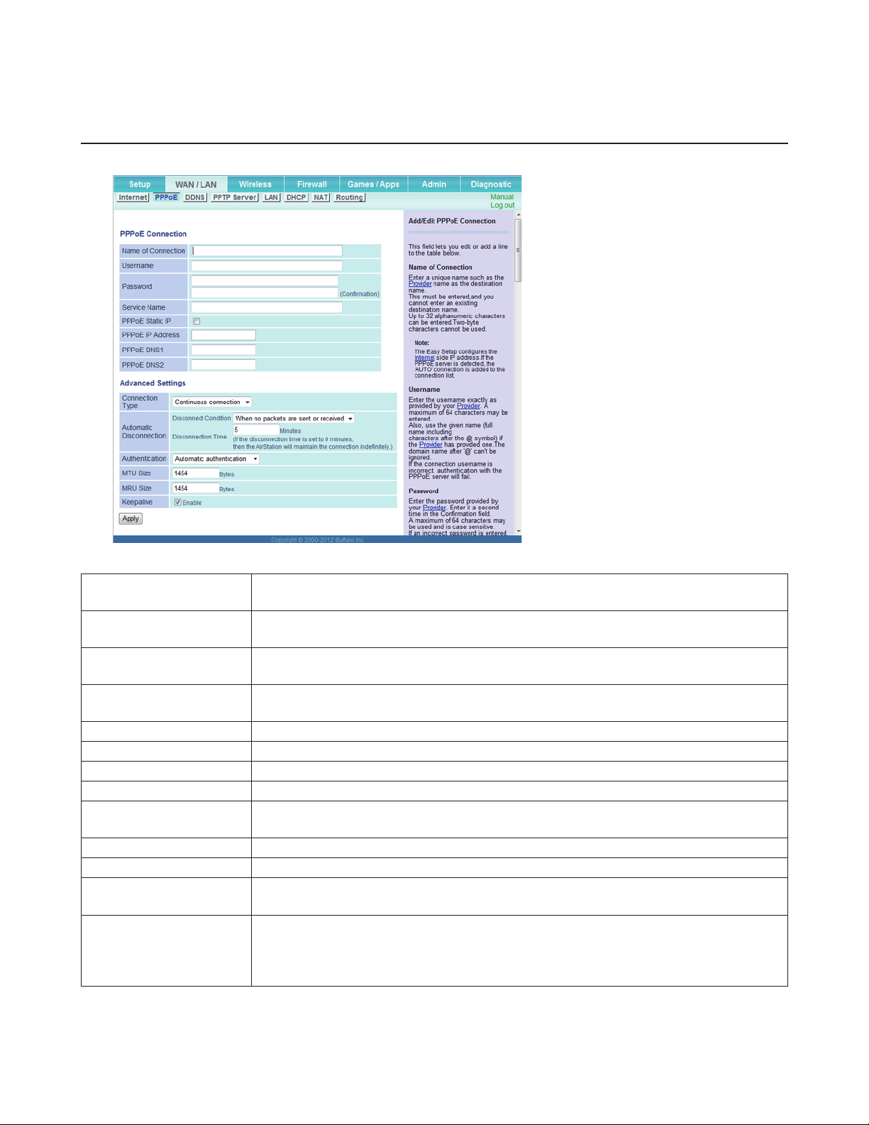
PPPoE
Configure PPPoE settings here. This function is only available when the AirStation is in router mode.
Name of Connection
Username
Password
Service Name
Enter the name to identify the connected destination. You may enter up to 32
alphanumerical characters and symbols.
Enter the username specified by your ISP for PPPoE certification. You may enter up to 64
alphanumerical characters and symbols.
Enter the password specified by your ISP for PPPoE certification. You may enter up to 64
alphanumerical characters and symbols.
Fill in this field only if your ISP specifies a service name. Leave blank otherwise. You may
enter up to 64 alphanumerical characters and symbols.
PPPoE Static IP Check to use a static IP address.
PPPoE IP Address Enter an IP address if you check PPPoE Static IP .
PPPoE DNS Enter the DNS address.
Connection Type Specifies the timing for the AirStation to connect to your ISP.
Automatic
Disconnection
Set time to disconnect after communication is stopped when the connection method is
set to Connection on demand or Manual . You can enter up to 1440 minutes.
Authentication Configure an authorization method with an ISP.
MTU Size Configure the MTU size for PPPoE. Values of 578 to 1492 bytes may be entered.
MRU Size
Configure MRU (maximum receive unit) for PPPoE. Values of 578 to 1492 may be
entered.
If keepalive is enabled, then the AirStation will issue an LCP echo request once a minute
Keepalive
in order to maintain the connection with the PPPoE. If the server does not respond for
more than 6 minutes, the line is recognized as disconnected and the AirStation will
terminate the connection.
16
Page 17
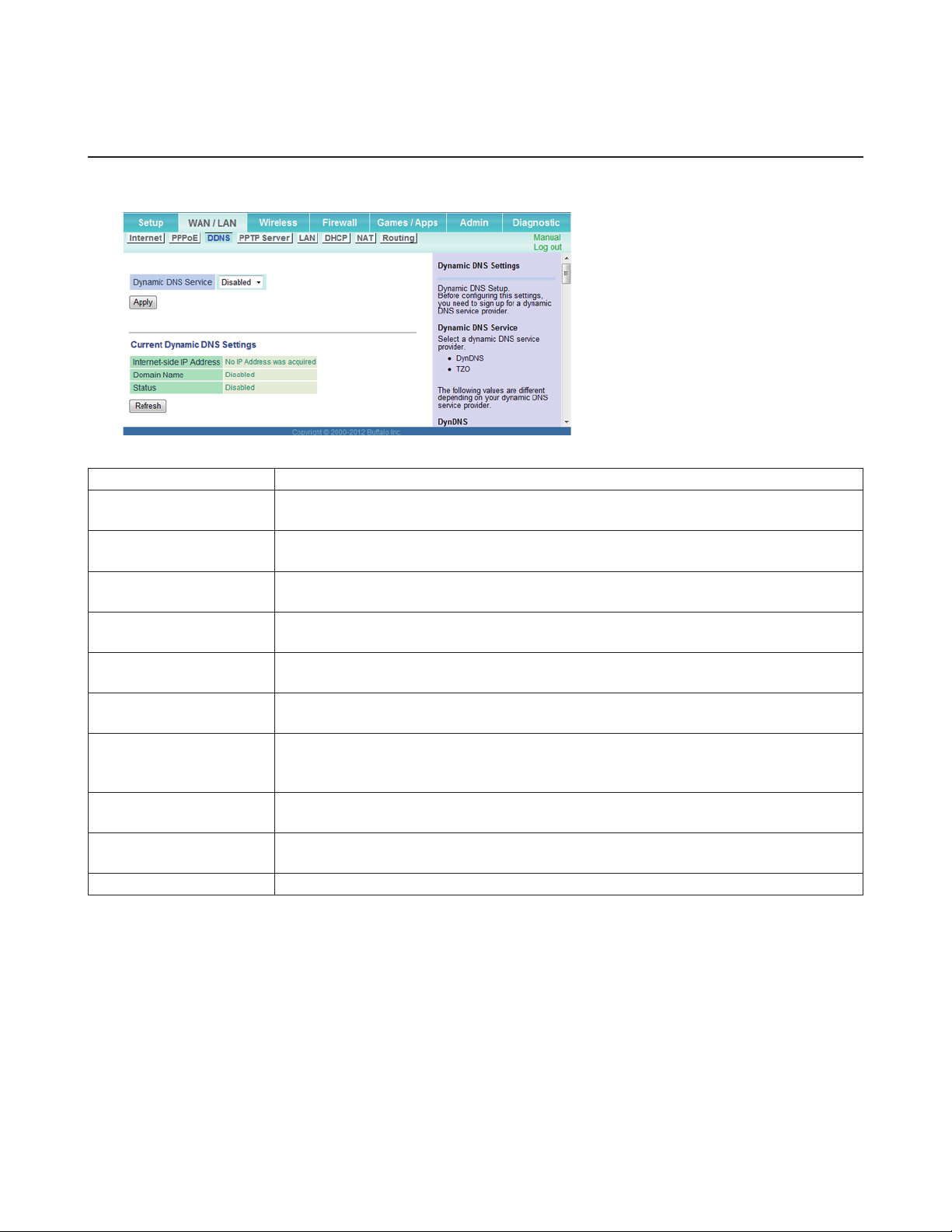
DDNS
Configure dynamic DNS settings here. Many settings are only available when the appropriate dynamic DNS service is
enabled. This function is only available when the AirStation is in router mode.
Dynamic DNS Service Select a provider (DynDNS or TZO) for dynamic DNS.
Username
Password
Hostname
Email Address
TZO Key
Domain Name
IP Address Update
Period
Internet-side IP Address
Domain Name
Enter the dynamic DNS username. You may enter up to 64 alphanumerical characters
and symbols.
Enter the dynamic DNS password. You may enter up to 64 alphanumerical characters
and symbols.
Enter the dynamic DNS hostname. You may enter up to 255 alphanumerical characters,
hyphens, and periods.
Enter the email address which is registered to the dynamic DNS service. You may enter
up to 64 alphanumerical characters and symbols.
Enter the TZO Key which is registered to the dynamic DNS service. You may enter up to
64 alphanumerical characters and symbols.
Enter the domain name which is registered to the dynamic DNS service. You may enter
up to 255 alphanumerical characters, hyphens, and periods.
Specifies the period to notify the dynamic DNS service provider of the current IP
address. For DynDNS, set it between 0 and 35 days. For TZO, set it between 0 and 99
days. If 0 (zero) days is set, no periodic update is performed.
The WAN-side IP address of the AirStation’s Internet port. This address is sent to the
dynamic DNS service provider.
The domain name assigned by the dynamic DNS service provider. The AirStation can be
accessed from the Internet using this domain name.
Status Displays the status of the dynamic DNS service.
17
Page 18
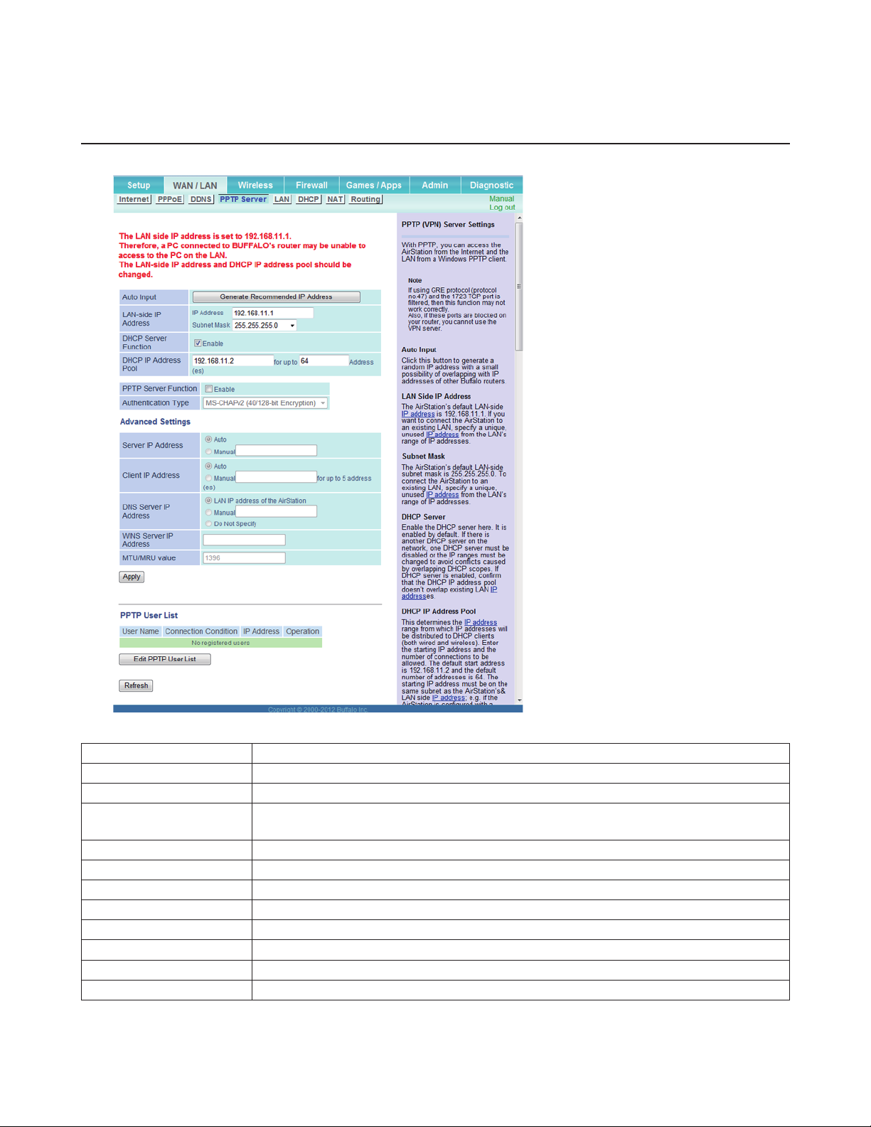
PPTP Server
Configure the PPTP server here. This function is only available when the AirStation is in router mode.
Auto Input Click to generate a random IP address.
LAN-side IP Address Set a LAN-side IP address and subnet mask.
DHCP Server Function Enable or disable the DHCP server, which assigns IP addresses automatically.
DHCP IP Address Pool
Configure the range of IP addresses to be assigned by the DHCP server and IP addresses
to be excluded from that range. Values from 1-256 may be entered.
PPTP Server Function Enable to use a PPTP server.
Authentication Type Select the authentication method for PPTP connection.
Server IP Address Select the server IP address.
Client IP Address Select the IP address range.
DNS Server IP Address Choose the IP address for the DNS server.
WINS Server IP Address Choose the IP address for the WINS server.
MTU/MRU value The MTU/MRU value is used by PPTP. Values from 578 to 1500 are supported.
Edit PPTP User List Click to edit user information.
18
Page 19
Click Edit PPTP User List to display.
Username
Enter the username to connect to the PPTP server. You may enter up to 16
Add new user
Advanced Settings
PPTP User List Displays the PPTP connection user information.
alphanumerical characters and symbols.
Password
Enter the password to connect to the PPTP server. You may enter up to 16
alphanumerical characters and symbols.
Click Edit PPTP User List to display.
Method of Acquiring IP Address
Select the method to be used to assign the IP address for the PPTP client.
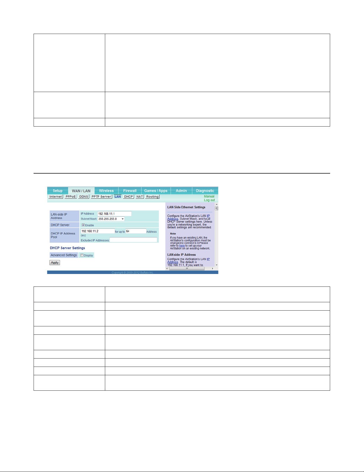
LAN
Configure LAN-side and DHCP Server settings here.
LAN-side IP Address
DHCP Server Enable or disable the DHCP server, which assigns LAN-side IP addresses automatically.
DHCP IP Address Pool
Advanced Settings Check Display to display DHCP server advanced settings options.
Lease Period
Default Gateway Set the default gateway IP address for the DHCP server to issue to clients.
DNS Servers Set the DNS server IP address for the DHCP server to issue to clients.
WINS Server Set the WINS server IP address for the DHCP server to issue to clients.
Domain Name
By default, the LAN-side IP address is 192.168.11.1 with subnet mask 255.255.255.0. You
may change it here.
Configure the range of IP addresses to be assigned by the DHCP server and IP addresses
to be excluded from that range. Values from 1-256 may be entered.
Set the effective period of an IP address assigned by the DHCP server. Up to 999 hours
may be entered.
Set the domain name for the DHCP server to issue to clients. You may enter up to 64
alphanumerical characters, hyphens, and periods.
19
Page 20
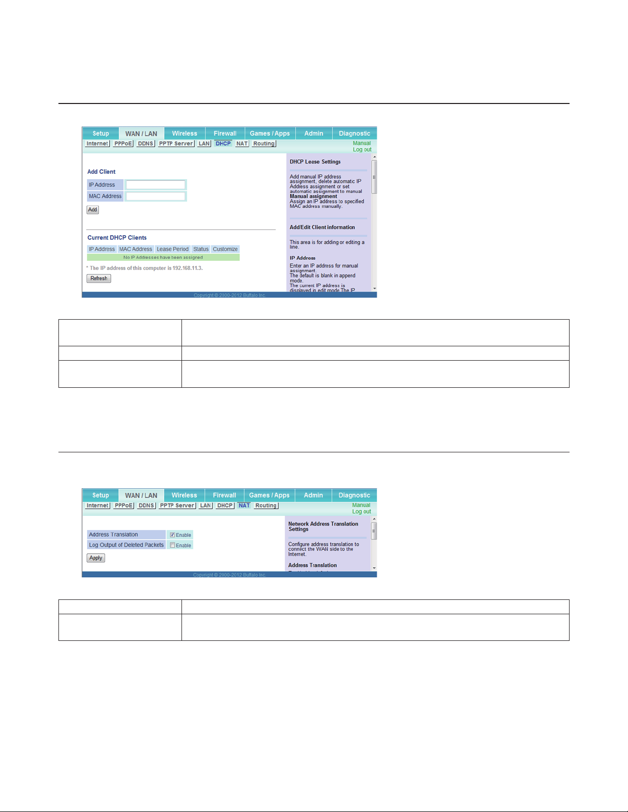
DHCP
Configure DHCP settings here. This function is only available when the AirStation is in router mode.
IP Address
MAC Address Enter the MAC address of the client.
Current DHCP Clients
Enter an IP address to lease manually. The IP address should be from the same subnet as
the DHCP scope, but not be within the range that DHCP is assigning to other devices.
Displays information for current leases. An IP address which is leased automatically can
be changed to manual leasing by clicking Manual Assignment .
NAT
Configure network address translation settings here. This enables LAN-side devices to communicate with the Internet.
This function is only available when the AirStation is in router mode.
Address Translation Enable to use network address translation (NAT).
Log Output of Deleted
Packets
Enable to log deleted packets (such as errors) during address translation.
20
Page 21
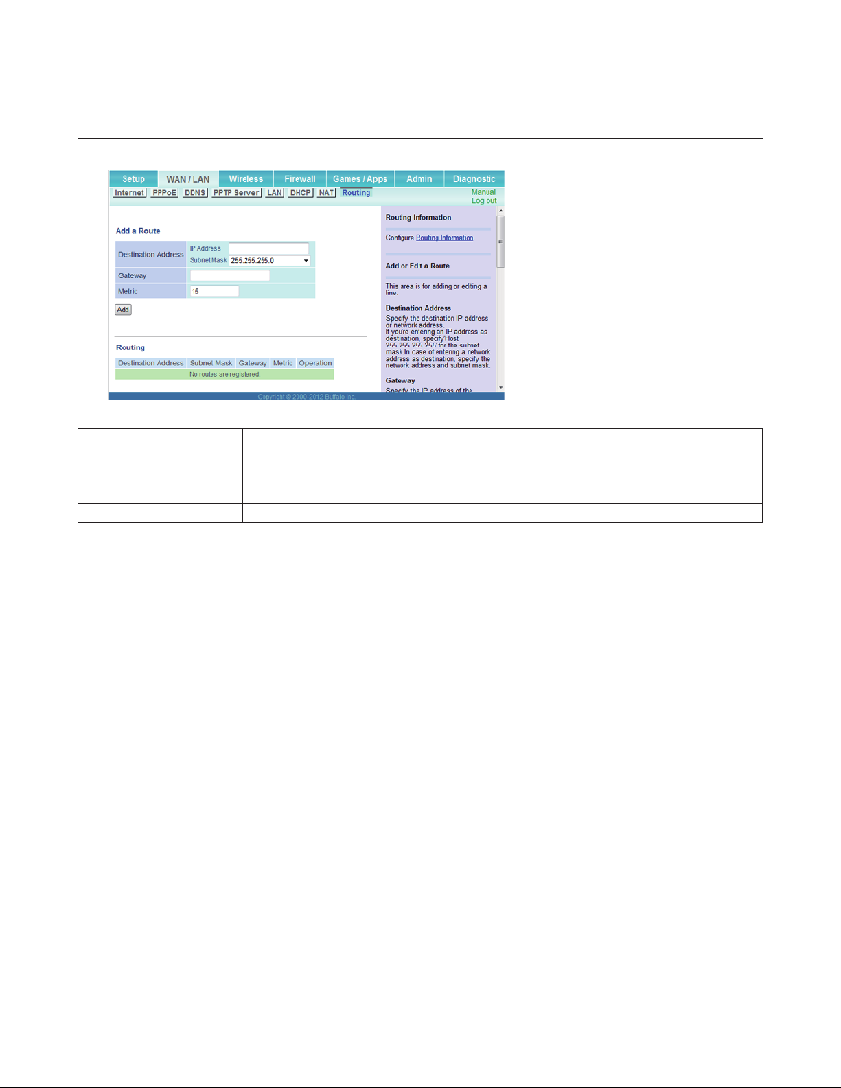
Routing
Configure the AirStation’s IP communication route here.
Destination Address Adds a destination IP address and subnet mask to the routing table.
Gateway Adds a gateway address to the routing table.
Metric
The metric is the maximum number of router hops a packet may take on the way to its
destination address. Values between 1 and 15 may be entered. The default value is 15.
Routing Manual entries will appear here after being added.
21
Page 22

Wireless
WPS
WPS is a system for configuring your wireless network automatically. If your wireless devices support WPS, you may
connect them by pushing buttons on the devices or by entering a PIN from one device into another.
WPS Enable to use WPS automatic configuration.
External Registrar
AirStation PIN
Enrollee PIN Enter the PIN code for the other wireless device and click OK .
WPS Status
Enable to accept configure requests from other WPS devices.
Note: Configure requests will not be accepted if AOSS is in use.
Displays the PIN code of the AirStation. Clicking Generate PIN will generate a new PIN
code. This code can be entered into other wireless devices that support WPS.
Displays “configured” if all available wireless bands are configured. Displays
“unconfigured” if at least one wireless band is unconfigured.
22
Page 23

AOSS
AOSS is a system for configuring your wireless network automatically. If your wireless devices support AOSS, you may
connect them by pushing buttons on the devices or in their software.
Initiates AOSS automatic wireless configuration. Click this, then press or click the AOSS
button on your AOSS-compatible wireless client. Repeat for additional AOSS clients.
Click this button to disconnect AOSS connections.
Note: If AOSS connections are disconnected, the SSID and encryption keys will be
restored to their last settings from before AOSS was used.
Exclusive SSID for WEP
Dedicated WEP SSID
isolation
AOSS Button on the
AirStation Unit
Current Security
Information
You may allow a separate SSID specifically for WEP connections. If “Disabled” is selected,
then clients will not be able to connect with WEP.
Set a separate SSID and network segment specifically for WEP connections. Devices
connected with WEP will not be able to communicate with devices connected using
AES. All connected devices will be able to communicate with the Internet.
Uncheck to disable the physical AOSS button on the AirStation.
Displays the encryption type, SSID, and encryption key configured by AOSS.
Random Click to enter random values for SSID, encryption key, and other settings.
23
Page 24

KEY Base
Reset
AOSS Client Information
Click to return the SSID, encryption key, and other wireless settings to the values on the
case sticker.
Click to return the SSID, encryption key, and other wireless settings to their previous
values.
Displays AOSS clients connected to the AirStation and information of the devices which
are wirelessly communicated.
Basic
Configure basic wireless settings here.
Wireless
Wireless Channel
High Speed Mode
Broadcast SSID
SSID 1
SSID 2 The multi-security SSID2 can use the WEP for wireless security.
SSID Isolation
Determines whether to allow wireless communication. If this is unchecked, then no
wireless connections will be allowed.
Sets a channel (a range of frequencies) for wireless connections. When “Auto Channel” is
selected, the AirStation will automatically use the best available channel.
High speed mode uses triple the normal frequency range, 40 MHz instead of 20 MHz.
In uncongested areas this can increase performance. To use high speed mode, set the
bandwidth to 40 MHz.
If Allow is checked, then the AirStation will respond to SSID searches from wireless
devices by broadcasting its SSID. If Allow is unchecked, then the AirStation ignores SSID
searches from wireless devices.
The multi-security SSID1 can use no authentication, WPA-PSK, WPA2-PSK, or WPA/WPA2
mixed mode - PSK for wireless security.
When enabled, wireless devices connected to the AirStation can communicate only with
the Internet side, not with each other.
24
Page 25

SSID Set SSID using 1 - 32 alphanumeric characters.
Authentication Specifies the authentication method used when connecting to a wireless device.
You may use any of the following types of encryption:
No encryption
Data is transmitted without encryption. With this setting, anyone within range can
connect to your wireless network and might be able to access data on the network. Not
recommended for anyone with private data that needs to be kept secure. No encryption
can be selected only when No authentication is selected for wireless authentication.
WEP
Encryption
WPA-PSK (Pre-shared
Key)
Key Renewal Interval Set the update interval for the encryption key between 0 and 1440 (minutes).
Setup WEP encryption
key
WEP is a common encryption method supported by most devices. WEP can only be
selected when wireless authentication is set to No authentication. Note that WEP’s
encryption is weak, and networks protected with WEP are not much more secure than
those with no encryption at all. Not recommended for anyone with private data that
needs to be kept secure.
AES
AES is very secure encryption method that is recommended for most users. Use a pre-
shared key to communicate with a wireless device. AES can be selected when WPA-PSK
or WPA2-PSK is selected for wireless authentication.
A pre-shared key or passphrase is the password for your wireless connections. There are
two different formats for a pre-shared key. Use 8 to 63 alphanumeric characters (case-
sensitive) for an ASCII passphrase, or use 64 alphanumeric characters (0 to 9 and a to f,
not case-sensitive) for a hexadecimal passphrase.
A WEP encryption key (passphrase) may have any of four different formats. An
ASCII passphrase may use either 5 or 13 alphanumeric characters (case-sensitive). A
hexadecimal passphrase may use either 10 or 26 alphanumeric characters (0 to 9 and a
to f, not case-sensitive).
25
Page 26

Advanced
Configure advanced wireless settings here.
Multicast Rate Set the communication speed of multi-cast packets.
Set the beacon responding interval (1 -255) for which the AirStation responds to a
DTIM Period
wireless device. This setting is effective only when power management is enabled for
the wireless device.
If enabled, the wireless client isolation blocks communication between wireless devices
Wireless Client Isolation
connected to the AirStation. Wireless devices will be able to connect to the Internet
but not with each other. Devices that are connected to the AirStation with wired
connections will still be able to connect to wireless devices normally.
26
Page 27

WMM
Set priorities for specific communications here.
WMM-EDCA
Parameters
You don’t usually need to change these settings. Using the default settings is recommended.
Priority
The following priorities may be applied to individual transmission packets: (Highest) 8, (High) 4,
(Normal) 2, and (Low) 1. From the queue, these packets are processed in order of priority.
CWmin , CWmax
The maximum and minimum value of the contention window. The contention window is used
in the frame collision avoidance structure performed in IEEE 802.11, and generally, the smaller
the value in the window, the higher the probability that the queue obtains the right to send.
AIFSN
The interval to send frames. The unit of the AIFSN is a slot, just as the window defined by
CWmin and CWmax is. The smaller the interval of sending frames, the faster the algorithm can
restart. As a result, the priority of the queue is higher.
TXOP Limit
The period of time that the queue can use after obtaining the right to send. The unit is 32 ms.
The longer this time, the more frames can be sent per right to send. However, the queue may
interfere with other packet transmissions. If TXOP limit is set to 0 (zero), only one frame can be
sent per right to send.
27
Page 28

MAC Filter
MAC filtering lets you restrict access your network. Only specific wireless devices will be able to connect.
Enforce MAC Filtering Enable to restrict wireless connections to devices with registered MAC addresses.
Registration List
Displays the MAC addresses of registered devices which are permitted to connect
wirelessly.
Edit Registration List Adds a wireless device to the list of permitted devices.
Enter MAC Addresses
List of Connected
Clients
Enter a MAC address of a wireless device to permit to connect to the AirStation. Click
Register to add that MAC address to the list.
Display the list of all MAC addresses of wireless devices connected to the AirStation.
28
Page 29

WDS
Configure WDS here. This function is only available when the AirStation is in bridge mode.
WDS
Connection Type
Connection Status Displays the connection status with the master.
SSID Specify an SSID to connect to the master manually.
Search Click this button to search for a master.
Authentication Specify the type of authentication used to connect to the master.
Encryption Specify the type of encryption used to connect to the master.
If enabled, the AirStation can connect to the wireless master by WDS. Disabled by
default.
Select the connection method to connect to the master. You may use AOSS or WPS to
connect push-button style, or specify an SSID to configure manually.
Multicast Control
Configure restrictions on unnecessary multicast packets sent to the wireless LAN port here.
Snooping
Multicast Aging Time
If enabled, snooping supervises multicast administrative packets such as IGMP and
restricts unnecessary multicast transfers to wired or wireless ports.
Set the time to hold the data from multicast snooping in the range of 1 to 3600
(seconds). Enter a value bigger than the IGMP/MLD query interval.
29
Page 30

Firewall
Firewall
Configure the AirStation’s firewall here. This function is only available when the AirStation is in router mode.
Log Output Enable to output a log of firewall activity.
Enable to use any of the quick filters. Preconfigured quick filters include:
Prohibit NBT and Microsoft-DS routing
Enabling this blocks communication using these protocols from the WAN side to the
LAN side or from the LAN side to the Internet. You can configure this with PPPoE if
you select Use PPPoE Client from the method of acquiring IP address, or if Easy Setup
identified a PPPoE connection during setup.
Reject ident requests
Basic Rules
Enabling this option will answer ident requests from the Internet side with
corresponding rejection packets. Enable this option if you experienced slow transfer
speeds for network applications such as mail, FTP or web browsing. If you have
configured transfer of ident requests to the LAN side computer in the address
translation settings (DMZ or TCP port 113), then that setting has higher priority and
overrides this setting.
Block ping from Internet
If this is enabled, the AirStation will not respond to pings from the WAN side. You can
configure this with PPPoE if you select Use PPPoE Client from the method of acquiring IP
address, or if Easy Setup identified a PPPoE connection during setup.
30
Page 31

IP Filter
Edit IP filters here. This function is only available when the AirStation is in router mode.
Log Output If enabled, IP filter activity is saved to a log.
Action Specify how to process target packets.
Direction Specify the transmission direction of target packets.
IP Address Specify the sender’s IP address and receiver’s IP address of the target packets.
Protocol Select a protocol for target transmission packet.
IP Filter Displays the list of IP filters which have been registered.
31
Page 32

VPN Passthrough
Configure IPv6 passthrough, PPPoE passthrough, and PPTP passthrough here. This function is only available when the
AirStation is in router mode.
IPv6 Passthrough Enable to use IPv6 passthrough for address translation.
Enable to use PPPoE bridging. PPPoE bridging lets you automatically obtain an IP
PPPoE Passthrough
address from your provider for your LAN-side computer using the PPPoE protocol
because PPPoE packets can pass between the Internet and LAN.
PPTP Passthrough Enable to use PPTP passthrough for address translation.
32
Page 33

Games / Apps
Port Forwarding
Configure port translation here. This function is only available when the AirStation is in router mode.
Specify a group name for a new rule to belong to. Select New Group and enter the new
Group
Internet-side IP Address Enter the Internet-side IP address (before translation) for the port translation table entry.
Protocol Select the Internet-side protocol (before translation) for the port translation table entry.
LAN-side IP Address Enter the LAN-side IP address (after translation) for the port translation table entry.
LAN-side Port
Forwarded Ports Displays current entries in the port translation table.
group name in the group name field to create a new group. A group name can include
up to 16 alphanumeric characters.
Select the LAN-side (after translation) port number (1 - 65535) for the port translation
table entry.
33
Page 34

DMZ
Configure a destination for packets that don’t have a LAN-side destination here. This function is only available when the
AirStation is in router mode.
IP Address of DMZ
Enter the IP address of a network device that will receive rejected packets. This device
will be accessible from outside the firewall.
Note: RIP protocol packets (UDP port number 520) will not be forwarded.
UPnP
Configure UPnP (Universal Plug and Play) here. This function is only available when the AirStation is in router mode.
UPnP Enable or disable Universal Plug and Play (UPnP) functionality.
34
Page 35

QoS
Configure the priority of packets sent to the Internet here. This function is only available when the AirStation is in router
mode.
QoS Check to enable QoS.
Upload Bandwidth
Specify the upstream bandwidth in kbps from the AirStation to the Internet side. Set the
actual value for the upstream bandwidth.
Enable Enable or disable this entry.
Application Name
Enter an application name. Names may use up to 32 alphanumerical characters, double
or single tick marks (“’), quotation marks (“), and semicolons (;).
Protocol Select either TCP or UDP.
Destination Port Specify a destination port from 1 - 65535. If this field is empty, a random port is selected.
Priority
Select high, medium, or low. If packets do not qualify for classification as a type on the
list, then their priority is treated as a level between medium and low.
35
Page 36

Admin
Name
Configure basic AirStation settings here.
AirStation Name
Network Services
Enter a name for the AirStation. Names may include up to 64 alphanumeric characters
and hyphens (-).
Enable or disable this to display the computers and devices on your network with their
supported services.
Password
Configure the password to log in to the AirStation’s configuration screen here.
Admin Name The name of the administrator account is “admin”.
Admin Password
The administrator password may contain up to 8 alphanumeric characters and
underscores (_).
36
Page 37

Time and Date
Configure the AirStation’s internal clock here.
Date You may manually set the date of the AirStation’s internal clock.
Local Time You may manually set the time of the AirStation’s internal clock.
Time Zone Specify the time zone (offset of Greenwich mean time) of the AirStation’s internal clock.
NTP
Configure an NTP server to automatically synchronize the AirStation’s internal clock here.
NTP Enable to use an NTP server. Enabled by default.
Enter the name of the NTP server as a hostname, hostname with domain name, or IP
NTP Server
Update Interval
address. Up to 255 alphanumeric characters, hyphens (-), underscores (_), and periods (.)
may be used. The default is “time.nist.gov”.
How often shall the AirStation check the NTP server for the correct time? Intervals of 1 -
24 hours may be set. The default is 24 hours.
37
Page 38

eco
Configure eco Mode here.
Scheduling
Enable to schedule eco Mode. If eco Mode is enabled, AOSS will function only when the
AirStation is in normal operating mode.
Weekly Schedule Graphically displays the configured schedule.
Schedule Entry
Configure operational mode for time periods in the weekly schedule. If custom mode is
chosen, configure it below.
Custom Mode Individual power saving elements may be configured for custom mode.
38
Page 39

Access
Restrict access to Settings here.
Log Output Enabling outputs a log of changes to access settings.
Prohibit configuration
from wireless LAN
Prohibit configuration
from wired LAN
Permit configuration
from wired WAN
Permitted IP Address
Permitted Port
If enabled, prevents access to Settings from wirelessly connected devices (only wired
devices may configure).
If enabled, prevents access to Settings from wired devices (only wirelessly connected
devices may configure).
If enabled, allows access to Settings from network devices on the WAN side.
Displayed only if WAN-side configuration is enabled. Enter the IP address of a device that
is permitted to configure the AirStation remotely from the WAN side.
Displayed only if WAN-side configuration is enabled. Set a port number (1 - 65535) to
configure the AirStation from the WAN side.
39
Page 40

Syslog Settings
Transfer the AirStation’s logs to a syslog server here.
Transfer Logs Enable to send logs to a syslog server.
Syslog Server
Logs Choose which logs will be transferred to the syslog server.
Identify the syslog server by hostname, hostname with domain name, or IP address. You
may enter up to 255 alphanumeric characters, hyphens (-) and periods (.).
Save/Restore
Save AirStation settings as a file and restore from them later.
Back Up Settings
Restore Settings
Clicking Back Up will save the current configuration of the AirStation to a file. If the
Encrypt the configuration file with a password option is checked, then the configuration
file will be password protected with the password.
Restore the configuration of the AirStation from a saved configuration file by clicking
Choose File , navigating to the configuration file, and then clicking Restore . If the
configuration file was password protected, check Open file with password , enter the
password, and click Restore .
40
Page 41

Initialize/Restart
Initialize or restart the AirStation.
Restart Click Restart Now to restart the AirStation.
Initialize Click Initialize Now to initialize and restart the AirStation.
Update
Update the AirStation’s firmware.
Firmware Version Displays the current firmware version of the AirStation.
Select a file on your PC updates from a firmware update file that you’ve downloaded to
Update Method
Firmware File Name
your computer. Automatic update will search the Internet for updated firmware and
update your firmware automatically when new firmware is available.
Click Choose File to navigate to the firmware file on your computer if Select a file on your
PC is selected. You don’t need to specify the firmware location if you’re using Automatic
update . Click Update Firmware to update the firmware.
41
Page 42

Diagnostic
System Info
View system information for the AirStation.
Model Displays the product name of the AirStation and the firmware version.
AirStation Name Displays the name of the AirStation.
Hardware Mode Switch
Status
Mode Displays the AirStation’s current operational mode.
Internet DDisplays the status of the WAN port.
LAN Displays the status of the LAN port.
Wireless Displays the wireless status.
WDS Displays the connection status of WDS.
eco Mode This indicates the operating status of eco Mode.
Displays the status of the AirStation’s mode switch.
42
Page 43

Logs
The AirStation’s logs are recorded here.
Display Logs Choose the types of logs to display.
Logs Displays the log information recorded in the AirStation.
Packet Info
View packet transfer information.
Sent Displays the number of packets sent to the WAN, the LAN, and the wireless LAN.
Received Displays the number of packets received from the WAN, the LAN, and the wireless LAN.
43
Page 44

Client Monitor
This screen shows devices that are connected to the AirStation.
Client Monitor
Displays information (MAC address, lease IP address, hostname, communication
method, wireless authentication and 802.11n) for devices that are connected to the
AirStation.
Ping
A ping test checks whether the AirStation can communicate with a specific network device.
Destination Address
Enter the IP address or hostname of the device that you are testing communication with,
then click Execute . The result will be displayed below.
44
Page 45

Chapter 4 - Connect to a Wireless Network
Automatic Secure Setup (AOSS / WPS)
AOSS and WPS are systems that enable you to automatically configure wireless LAN settings. Just pressing the buttons
will connect wireless devices and complete security settings. Use them to automatically connect wireless devices,
computers, or game machines which support AOSS or WPS.
AOSS (AirStation One-Touch Secure System) is technology developed by Buffalo Technology. WPS was created by the
Wi-Fi alliance.
• Before using AOSS or WPS to connect the Buffalo wireless client to the computer, download Client Manager or AOSS
Assistant from the Buffalo website and install it.
• Buffalo’s Client Manager software can be used with the wireless LAN devices built into your computer. However, it is
not guaranteed to work with all wireless LAN devices available.
45
Page 46

Windows 8, Windows 7 or Windows Vista (Client Manager V)
If you are using Windows 8, Windows 7 or Windows Vista, use Client Manager V to connect wirelessly with AOSS or WPS.
1 Launch Client Manager V.
2 Click Create Profile.
3 If the “User Account Control” screen opens, click Yes or Continue.
4 Click WPS AOSS.
When the wireless LED on the front of the AirStation stops flashing and glows steadily, the connection is ready to use.
46
Page 47

Windows XP (Client Manager 3)
If you are using Windows XP, use Client Manager 3 to connect wirelessly with AOSS or WPS.
1 Right-click the icon in the system tray and select Profile.
2 Click WPS AOSS.
It will take several seconds for your wireless connection to be configured. When the wireless LED on the front of the
AirStation stops flashing and glows steadily, the connection is ready to use.
Mac OS (AOSS Assistant)
If you are using Mac OS X 10.8, 10.7, 10.6, 10.5 or 10.4, use AOSS Assistant to connect wirelessly with AOSS.
1 Download AOSS Assistant from Buffalo’s website.
2 Open the AOSS Assistant software. Click Agree to proceed.
47
Page 48

3 Click Start AOSS.
4 Enter the Mac’s username and password and click OK.
It will take several seconds for your wireless connection to be configured. When the wireless LED on the front of the
AirStation stops flashing and glows steadily, the connection is ready to use.
Other Devices (e.g. Game Console)
If you are using a game machine which supports AOSS or WPS, refer to that device’s manual to initiate AOSS or WPS.
When instructed, hold down the AOSS button on the AirStation for 1 second.
When the wireless LED on the front of the AirStation stops flashing and glows steadily, the connection is ready to use.
48
Page 49

Manual Setup
You can also connect to the AirStation without installing Client Manager V or Client Manager 3 by using the utility builtin to the operating system. The procedure varies depending on which operating system you are using.
Windows 8 (WLAN AutoConfig)
With Windows 8, use WLAN AutoConfig to connect to the AirStation.
1 Switch Windows 8 to desktop mode.
2 Click the network icon in the system tray.
3 Select the target AirStation’s name and click Connect. If you will be connecting to this device again, check Connect
automatically.
4 Enter the encryption key and click Next.
49
Page 50

5 Click No, don’t turn on sharing or connect to devices.
Windows 7 (WLAN AutoConfig)
With Windows 7, use WLAN AutoConfig to connect to the AirStation.
1 Click the network icon in the system tray.
2 Select the target AirStation and click Connect. If you will be connecting to this device in the future, checking
Connect automatically is recommended.
50
Page 51

3 Enter the encryption key and click OK.
Windows Vista (WLAN AutoConfig)
With Vista, use WLAN AutoConfig to connect to the AirStation.
1 Right-click the wireless network icon in the system tray.
2 Click Connect to a network.
3 When this screen is displayed, select your network and click Connect.
51
Page 52

If the screen below is displayed, click I want to enter the network key or passphrase instead.
Otherwise, go to step 4.
52
Page 53

4 Enter the encryption key and click Connect.
Step through the wizard to finish configuration.
If the “Set Network Location” screen is displayed, select Home, Work, or Public location depending on where you’re using
the AirStation.
Windows XP (Wireless Zero Configuration)
Windows XP includes Wireless Zero Config, a built-in utility to connect to your AirStation.
Note: If Client Manager 3 is installed on your computer, Wireless Zero Config is disabled. Uninstall Client Manager 3
to use Wireless Zero Config, or just use Client Manager 3 to connect to the AirStation.
1 Right-click the image wireless network icon in the system tray.
2 Click View Available Wireless Networks.
53
Page 54

3 Select the network to connect to and click Connect.
4 Enter the encryption key (twice) and click Connect.
It will take several seconds for configuration to complete.
54
Page 55

Mac OS (Wi-Fi)
Use Wi-Fi on a Mac to connect to the AirStation.
Note: In Mac OS 10.6 and earlier, “Wi-Fi” appears as “AirPort”.
1 Click the icon in the top section of the screen and select Turn Wi-Fi On.
2 Find the SSID from step 1 on the list. Click it to highlight it.
3 Enter your encryption key in the password field, check Remember this network, and click Join.
It will take several seconds for configuration to complete.
55
Page 56

Chapter 5 - Troubleshooting
Cannot Connect to the Internet Over a Wired Connection.
• Make sure that your AirStation is plugged in!
• Check that the status LEDs of your AirStation are lit as below:
Power/Diag: Green LED is on
Wireless: Green or amber LED is on
• Make sure that your computer is configured to “obtain an IP address automatically from DHCP”.
• Restart your AirStation.
Cannot Access Settings.
• See chapter 3 for instructions to open Settings.
• Enter the correct username and password to log in to Settings. If you are using AirStation with factory default
settings, enter “admin” for the username and “password” for the password.
• Verify that your web browser is not set to use proxies.
• Make sure that your computer is configured to “obtain an IP address automatically from DHCP”.
• Restart your AirStation.
56
Page 57

Cannot Connect to the Network Wirelessly.
• Configure your wireless client with the same SSID, encryption type, and encryption key as set on the AirStation.
The factory defaults are:
SSID (11n/g/b) - Buffalo-G-XXXX (the last 4 digits of the AirStation’s MAC address)
Encryption Type - WPA2 - PSK AES
Encryption Key - Printed on the setup card.
Note: For details, refer to the setup card.
• Place your AirStation and wireless devices 2 - 10 feet apart.
• Restart your AirStation.
Forgot AirStation’s SSID, Encryption Key, or Password.
Hold down the reset button on the base of your AirStation for 3 seconds to initialize its settings. All settings, including
your password, SSID, and encryption key will be initialized to their defaults.
With the AirStation powered on, hold down this button for 3 seconds to return it to factory default settings.
57
Page 58

How to Configure TCP/IP
Windows 8
To configure TCP/IP in Windows 8, follow the procedure below.
1 Open Control Panel.
2 Click Network and Internet.
3 Click Network and Sharing Center.
4 Click Change Adapter Settings on the left side menu.
5 Right-click the network adapter, then click Properties.
6 If the “User Account Control” screen opens, click Yes or Continue.
7 Select Internet Protocol Version 4 (TCP/IPv4) then click Properties.
8 To have DHCP set your IP address settings automatically, check Obtain an IP address automatically and Obtain DNS
server address automatically.
Alternately, you can configure the settings manually. Example:
If the router’s IP address is 192.168.11.1,
IP address: 192.168.11.80
Subnet mask: 255.255.255.0
Default gateway: 192.168.11.1
Preferred DNS server: 192.168.11.1
Alternate DNS server: blank
9 Click OK.
58
Page 59

Windows 7
To configure TCP/IP in Windows 7, follow the procedure below.
1 Open Control Panel.
2 Click Network and Sharing Center.
3 Click Change Adapter Settings on the left side menu.
4 Right-click the network adapter, then click Properties.
5 If the “User Account Control” screen opens, click Yes or Continue.
6 Select Internet Protocol Version 4 (TCP/IPv4) then click Properties.
7 To have DHCP set your IP address settings automatically, check Obtain an IP address automatically and Obtain DNS
server address automatically.
Alternately, you can configure the settings manually. Example:
If the router’s IP address is 192.168.11.1,
IP address: 192.168.11.80
Subnet mask: 255.255.255.0
Default gateway: 192.168.11.1
Preferred DNS server: 192.168.11.1
Alternate DNS server: blank
8 Click OK.
59
Page 60

Windows Vista
To configure TCP/IP in Windows Vista, follow the procedure below.
1 Open Control Panel.
2 Click Network and Sharing Center.
3 Click Manage network connections on the left side menu.
4 Right-click the network adapter, then click Properties.
5 If the “User Account Control” screen opens, click Yes or Continue.
6 Select Internet Protocol Version 4 (TCP/IPv4) then click Properties.
7 To have DHCP set your IP address settings automatically, check Obtain an IP address automatically and Obtain DNS
server address automatically.
Alternately, you can configure the settings manually. Example:
If the router’s IP address is 192.168.11.1,
IP address: 192.168.11.80
Subnet mask: 255.255.255.0
Default gateway: 192.168.11.1
Preferred DNS server: 192.168.11.1
Alternate DNS server: blank
8 Click OK.
60
Page 61

Windows XP
To configure TCP/IP in Windows XP, follow the procedure below.
1 Open Control Panel.
2 Double-click Network.
3 Right-click the network adapter, then click Properties.
4 Select Internet Protocol (TCP/IP) then click Properties.
5 To have DHCP set your IP address settings automatically, check Obtain an IP address automatically and Obtain DNS
server address automatically.
Alternately, you can configure the settings manually. Example:
If the router’s IP address is 192.168.11.1,
IP address: 192.168.11.80
Subnet mask: 255.255.255.0
Default gateway: 192.168.11.1
Preferred DNS server: 192.168.11.1
Alternate DNS server: blank
6 Click OK.
Mac OS
To configure TCP/IP in Mac OS, follow the procedure below.
1 Click Apple menu > System Preferences….
2 Click Network.
3 Click the network adapter.
4 To have DHCP set your IP address settings automatically, select Using DHCP in the “Configure IPv4” field.
Alternately, you can configure the settings manually. Example:
If the router’s IP address is 192.168.11.1,
IP address: 192.168.11.80
Subnet mask: 255.255.255.0
Default gateway: 192.168.11.1
Preferred DNS server: 192.168.11.1
Alternate DNS server: blank
5 Click Apply.
61
Page 62

Other Tips
Issue:
I reset my wireless router to factory settings and forgot how to log in to Settings.
Answer:
Open your browser, enter 192.168.11.1 as the browser address, and hit the enter key. You will be prompted to log in.
Enter “admin” for the username and “password” for the password. Click OK to log in. The option to reset your password
will be available on the first page.
Issue:
How do I forward ports on my wireless router for my gaming console?
Answer:
Log in Settings and navigate to Internet Games (Port Forwarding) on Setup page. Enter the port that needs to be
forwarded and the IP address of the gaming console.
Issue:
How do I enable or modify security encryption settings on the wireless router?
Answer:
Log in Settings and navigate to Wireless Encryption on Setup page. Buffalo recommends the use of WPA2-PSK AES for
wireless encryption. The passphrase/key should be at least 8 characters in length.
Issue:
How do I change my wireless router’s broadcasted network name (SSID)?
Answer:
Log in Settings and navigate to Wireless - Basic. Find the SSID setting. Select Use and enter the new name for your
network. Click Apply. Once the wireless router has rebooted, you will need reconnect any wireless clients to the
AirStation using the new network name. The encryption key will still be the same.
Issue:
What can I do if my wireless connection drops randomly or seems slow?
Answer:
There are many environmental factors that may cause this. First, ensure the issue is not range related by moving the
wireless router and the client device closer together. If the connection drops continue, then range is probably not the
issue.
Other 2.4 GHz devices such as microwaves, other wireless networks, and 2.4 GHz wireless phones may impact
performance. Try a different wireless channel for your wireless router. Log in Settings and navigate to Basic Wireless
Setup on Setup page. Wireless channels from 1 - 11 may be selected. Try “Auto Channel” option if available. Otherwise,
manually select an alternate channel and click Apply.
Issue:
Though I am able to successfully make a connection with my wireless router, I am unable to access the Internet with my
web browser.
Answer:
First, press the router button on the AirStation to switch to router mode. The router LED on the AirStation turns on,
and after about one minute, turn off the cable or DSL modem, AirStation, and your computer. Verify that the modem
is connected to the Internet port on the AirStation with a Ethernet cable. Power on the modem and wait one minute.
Power on the wireless router and wait another minute. Power on the computer. Open a browser on the computer and
navigate to a familiar website to verify whether the Internet connection is functioning normally.
If after these steps, an Internet connection is still unavailable, power off the cable or DSL modem and computer again
and directly connect your computer to the cable or DSL modem with a cable between the computer and the port
on the modem. Power on the modem and wait one minute. Power on the computer and again check for an Internet
62
Page 63

connection.
If an Internet connection IS NOT available with a direct connection to the computer, please call the Internet Service
Provider who installed the modem.
If an Internet connection IS available with a direct connection to the computer, please call our customer support.
Issue:
Where can I download the latest drivers, firmware, and instructions for my Buffalo wireless products?
Answer:
The latest drivers and firmware are available online at www.buffalotech.com
63
Page 64

Chapter 6 - Default Configuration Settings
Feature Parameter Default Setting
Method of Acquiring IP Address Perform Easy Setup (Internet Connection Wizard)
Default Gateway -
Internet
PPPoE
DDNS
PPTP Server
LAN
DNS Name Server Address Internet MAC Address Use default MAC address
MTU Size of Internet Port 1500 Bytes
Connection Type Continuous connection
Disconnect Condition:
Automatic Disconnection
Authentication Automatic Authentication
MTU Size 1454 Bytes
MRU Size 1454 Bytes
Keepalive Enabled
Dynamic DNS Service Disabled
Current Dynamic DNS Settings LAN-side IP Address 192.168.11.1 (255.255.255.0)
DHCP Server Function Enabled
DHCP IP Address Pool 192.168.11.2 for up to 64 Address(es)
PPTP Server Function Disabled
Authentication Type MS-CHAPv2 (40/128-bit Encryption)
Server IP Address Auto
Client IP Address Auto
DNS Server IP Address LAN IP address of the AirStation
WINS Server IP Address MTU/MRU Value 1396
PPTP User List No registered users
LAN-side IP Address
DHCP Server Enabled
DHCP IP Address Pool 192.168.11.2 for up to 64 addresses
Lease Period 48 Hours
Default Gateway AirStation’s IP address
When no packets are sent or received
Disconnection Time:
5 Minutes
Router mode (Router on):
192.168.11.1 (255.255.255.0)
Bridge mode (Router off):
192.168.11.100 (255.255.255.0)
Bridge mode (when the mode switch is in the Auto
position):
Obtain automatically from DHCP server
64
Page 65

Feature Parameter Default Setting
DNS Servers AirStation’s IP address
LAN
DHCP Current DHCP Clients -
NAT
Routing Routing No routes are registered.
WPS
AOSS
Basic
Advanced
WINS Server Assigned IP address
Domain Name Assigned domain name
Address Translation Enabled
Log Output of Deleted Packets Disabled
WPS Enabled
External Registrar Enabled
AirStation PIN
WPS Security Settings
Exclusive SSID for WEP AOSS is not in use.
Dedicated WEP SSID isolation Disabled
AOSS Button on the AirStation
Unit
Wireless Enabled
Wireless Channel Auto Channel
High Speed Mode Bandwidth: 20 MHz
Broadcast SSID Allow
SSID1 Enabled
SSID Isolation Not used
SSID Use AirStation’s MAC address
Authentication WPA2 - PSK
Encryption AES
WPA-PSK (Pre-Shared Key) The 8-digit random number printed on the setup card.
SSID2: WEP Disabled
Key Renewal Interval 60 minutes
Multicast Rate 1 Mbps
DTIM Period 1
Wireless Client Isolation Disabled
An 8-digit random value (Printed on the label of the
AirStation)
WPS status:
configured
SSID:
Buffalo-G-XXXX (the last 4 digits of the AirStation’s MAC
address)
Security:
WPA2 - PSK AES
Encryption key:
The 8-digit random number printed on the setup card.
Enabled
65
Page 66

Feature Parameter Default Setting
For AP For STA
WMM-EDCA Parameters (Priority
AC_BK (Low) )
WMM-EDCA Parameters (Priority
AC_BE (Normal) )
WMM
WMM-EDCA Parameters (Priority
AC_VI (High) )
WMM-EDCA Parameters (Priority
AC_VO (Highest) )
MAC Filter
WDS WDS Disabled
Multicast
Control
Firewall
IP Filter
VPN
Passthrough
Port Forwarding Forwarded Ports Port forwarding has not been configured yet.
DMZ IP Address of DMZ UPnP UPnP Enabled
QoS QoS Disabled
Name
Password
Time and Date
Enforce MAC Filtering Disabled
Registration List No registered MAC addresses
Snooping Disabled
Multicast Aging Time 300 Sec.
Log Output Disabled
Basic Rules
Log Output Disabled
IP Filter No IP filters have been configured yet.
IPv6 Passthrough Disabled
PPPoE Passthrough Disabled
PPTP Passthrough Disabled
AirStation Name AP + AirStation’s MAC Address
Network Services Enabled
Admin Name admin (fixed)
Admin Password password
Local Date 2010 Year 1 Month 1 Day
Local Time 0 Hour 0 Minute 0 Seconds
Time Zone (GMT+00:00) Greenwich Mean Time, London
CWmin 15 15
CWmax 1023 1023
AIFSN 7 7
TXOP Limit 0 0
For AP For STA
CWmin 15 15
CWmax 63 1023
AIFSN 3 3
TXOP Limit 0 0
For AP For STA
CWmin 7 7
CWmax 15 15
AIFSN 1 2
TXOP Limit 94 94
For AP For STA
CWmin 3 3
CWmax 7 7
AIFSN 1 2
TXOP Limit 47 47
Prohibit NBT and Microsoft-DS routing: Disabled
Reject ident requests: Enabled
Block ping from Internet: Enabled
66
Page 67

Feature Parameter Default Setting
NTP Enabled
NTP
eco
Access
Syslog Settings
Update Update Method Select a file on your PC
NTP Server time.nist.gov
Update Interval 24 hours
Scheduling Disabled
Power Saving Mode: Normal
Schedule Entry
User Define Mode
Log Output Disabled
Management Access
Transfer Logs Disabled
Syslog Server -
Logs
Start Time: 0:00
End Time: 0:30
Day of Week: none
LED: Off
Wired LAN: eco (Slow operation)
Wireless LAN: Off
Prohibit configuration from wireless LAN:
Disabled
Prohibit configuration from wired LAN:
Disabled
Permit configuration from wired WAN:
Disabled
Address Translation, IP Filter, Firewall, PPPoE Client,
Dynamic DNS, DHCP Client, DHCP Server, AOSS, Wireless,
Authentication, Setting Changes, System Boot, NTP Client,
and Wired
67
Page 68

Appendix A - Supplemental Information
Technical Specifications
Wireless LAN Interface
Standard Compliance IEEE 802.11n / IEEE 802.11g / IEEE 802.11b
Transmission Method Direct Sequence Spread Spectrum (DSSS), OFDM, MIMO
Frequency Range Available frequencies depend on the country of purchase.
IEEE 802.11n 20 MHz BW <Long GI>:
130/117/104/78/52/39/26/13 Mbps (2 stream)
65/58.5/52/39/26/19.5/13/6.5 Mbps (1 stream)
IEEE 802.11n 20 MHz BW <Short GI>:
144.4/130/115.6/86.7/57.8/43.3/28.9/14.4 Mbps (2 stream)
72.2/65/57.8/43.3/28.9/21.7/14.4/7.2 Mbps (1 stream)
IEEE 802.11n 40 MHz BW <Long GI>:
Transmission Rate
Access Mode Infrastructure Mode
Security
Wired LAN Interface
Standard Compliance IEEE 802.3u (100BASE-TX) / IEEE 802.3 (10BASE-T)
Transmission Rate 10 / 100 Mbps
Transmission Encoding 100BASE-TX 4B5B/MLT-3, 10BASE-T Manchester Coding
Access Method CSMA/CD
Speed and Flow Control 10 / 100 Mbps, Auto Sensing, Auto MDIX
Number of LAN Ports 5
Other
Power Supply External AC 100-240 V Universal, 50/60 Hz
Power Consumption About 10.2 W (Max)
Dimensions 55 x 130.5 x 159 mm (2.17 x 5.14 x 6.26 in.)
Weight 265 g (9.3 oz.)
Operating Environment 0 - 40° C (32 - 104° F), 10 - 85% (non-condensing)
270/243/216/162/108/81/54/27 Mbps (2 stream)
135/121.5/108/81/54/40.5/27/13.5 Mbps (1 stream)
IEEE 802.11n 40 MHz BW <Short GI>:
300/270/240/180/120/90/60/30 Mbps (2 stream)
150/135/120/90/60/45/30/15 Mbps (1 stream)
IEEE 802.11g:
54/48/36/24/18/12/9/6 Mbps
IEEE 802.11b:
11/5.5/2/1 Mbps
AOSS, WPA/WPA2 mixed PSK, WPA2-PSK (AES), WPA-PSK (AES), 64-bit or 128-bit WEP,
Mac Address Filter
68
Page 69

Environmental Information
• The equipment that you have purchased has required the extraction and use of natural resources for its production.
• The equipment may contain hazardous substances that could impact health and the environment.
• In order to avoid the dissemination of those substances in our environment and to diminish the pressure on the
natural resources, we encourage you to use the appropriate take-back systems.
• The take-back systems will reuse or recycle most of the materials of your end life equipment in a sound way.
• The crossed-out wheeled bin symbol invites you to use those systems.
• If you need more information on collection, reuse, and recycling systems, please contact your local or regional waste
administration.
GPL Information
The source code for Buffalo products that use GPL code is available at http://opensource.buffalo.jp/ .
69
 Loading...