

Page 1
AirStation
WHR-1166D
User Manual
www.buffalotech.com
35020394-01
2014-02
Page 2

Contents
Chapter 1 - Setup ...............................................................7
Introduction .........................................................................................7
Diagrams and Layout ...........................................................................7
Front Panel ......................................................................................................7
Back Panel .......................................................................................................9
Bottom ...........................................................................................................10
How to Set Up AirStation for the First Time .....................................10
Connect to a PC and Power On .....................................................................10
Opening Settings ..........................................................................................13
Connect Your Wireless Devices ....................................................................14
Chapter 2 - Settings .........................................................15
Easy Admin .........................................................................................15
Home ..............................................................................................................15
Wireless ..........................................................................................................16
AOSS/WPS......................................................................................................17
Guest Accounts .............................................................................................17
Web Filtering .................................................................................................18
Network Devices ...........................................................................................19
Advanced Settings .............................................................................20
Internet ..........................................................................................................20
PPPoE .............................................................................................................21
Dynamic DNS .................................................................................................23
NAT .................................................................................................................24
2
Page 3

LAN .................................................................................................................24
DHCP Lease....................................................................................................25
Routing ..........................................................................................................25
2.4 GHz/5 GHz ...............................................................................................26
WPS ................................................................................................................29
AOSS...............................................................................................................29
MAC Filtering .................................................................................................32
Multicast Control ..........................................................................................32
Guest Accounts .............................................................................................33
WB ..................................................................................................................34
Firewall ..........................................................................................................35
IP Filter ...........................................................................................................36
VPN Passthrough ..........................................................................................36
Port Forwarding ............................................................................................37
DMZ ................................................................................................................38
UPnP ...............................................................................................................38
Web Filtering .................................................................................................39
Access Control ...............................................................................................40
QoS .................................................................................................................40
eco Mode .......................................................................................................41
System ...........................................................................................................42
Syslog Settings ..............................................................................................43
Reset / Reboot ...............................................................................................44
Update Firmware ..........................................................................................45
System Information ......................................................................................46
Logs ................................................................................................................47
Packets ...........................................................................................................47
Ping ................................................................................................................48
3
Page 4

Chapter 3 - Wireless .........................................................49
Wireless Options ................................................................................49
Advanced Wireless Configuration ....................................................50
Manual Configuration (SSID and Password) ...............................................50
Automatic Secure Setup (WPS) ....................................................................50
Automatic Secure Setup (AOSS) ..................................................................51
Chapter 4 - Utilities ..........................................................52
How to Download Utilities ................................................................52
List of Utilities with Description of Each ..........................................53
AirStation Configuration Tool ......................................................................53
Client Manager ..............................................................................................54
AOSS Assistant ..............................................................................................55
WLAN Monitor ...............................................................................................55
Chapter 5 - Troubleshooting ...........................................56
Finding Your AirStation on the Network ..........................................56
Eliminating Dead Spots in Wireless Coverage .................................56
If Your Wireless Connection Is Not Stable .........................................56
Basic Router Troubleshooting ...........................................................56
Basic Router Troubleshooting from a Mac .......................................57
Appendix A - Supplemental Information ......................58
Package Contents ...............................................................................58
Factory Default Settings ....................................................................58
4
Page 5

Technical Specifications ....................................................................63
GPL Information .................................................................................64
Appendix B - Tutorials .....................................................65
Configuring the AirStation for Optimal Performance and Security
Performance ..................................................................................................65
Security ..........................................................................................................65
...65
Configuring the Web Filter ................................................................66
Content Filter ................................................................................................66
Websites Excluded from Filter .....................................................................66
Computers Excluded from Filter ..................................................................67
Finding a Computer’s MAC Address ............................................................67
Configuring Access Control ...............................................................68
Port Forwarding Basics ......................................................................69
Common Uses ................................................................................................69
Security ..........................................................................................................69
UPnP ...............................................................................................................69
Setting Up Port Forwarding Rules ....................................................70
Creating Port Forwarding Rules ..................................................................70
Managing Port Forwarding Rules ................................................................71
Adding the AirStation to a Wireless Network ..................................71
Set Up the AirStation as an Extender ..........................................................71
Saving and Restoring Settings with a Backup File ..........................73
Save Settings to a Backup File .....................................................................73
Restoring Settings with a Backup File .........................................................74
Replacing the AirStation ..............................................................................74
5
Page 6

Connecting Wireless Devices Using AOSS ........................................75
Pushbutton Method .....................................................................................75
Using AirStations with 2Wire Residential Gateways .......................75
How to Use QoS ..................................................................................76
Setting a QoS Priority Policy ........................................................................76
How to Configure TCP/IP ...................................................................77
Windows 8.1/Windows 8 ..............................................................................77
Windows 7 .....................................................................................................77
Windows Vista ...............................................................................................78
Windows XP ...................................................................................................79
Mac OS ...........................................................................................................79
Appendix C - Regulatory Compliance Information .......80
Company Information .......................................................................80
FCC Statement ....................................................................................80
IC statement (IC déclaration) .............................................................81
EU Regions of Intended Using ...........................................................82
NCC Statement ...................................................................................82
6
Page 7
Chapter 1 - Setup
Introduction
Thank you for purchasing a Buffalo AirStation. The WHR-1166D AirStation is a dual-band wireless router with
outstanding performance and range. It combines high data transfer speeds with a robust set of extra features like QoS,
guest accouts, eco mode, and web filtering. This manual will help you set up and use your new wireless router.
For advanced users, use a wired Ethernet connection to access the AirStation’s settings:
• Default LAN-side IP address: 192.168.11.1
• Username: admin
• Default password: password
Diagrams and Layout
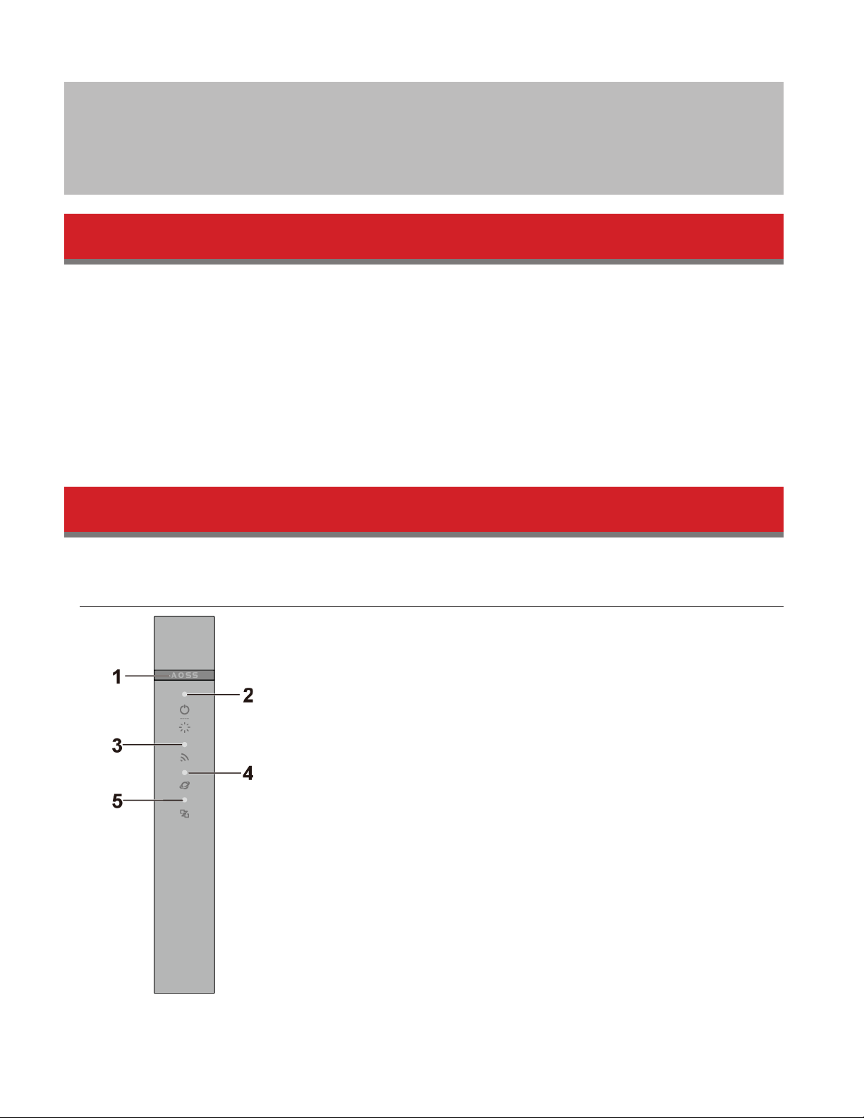
Front Panel
7
Page 8

1 AOSS button
To initiate AOSS, hold down this button until the wireless LED flashes (about 3 second). Then, push or click the
AOSS button on your wireless client device to complete the connection. Both devices must be powered on.
2 Power/Diag LED (Green or Amber)
On (Green):
Power is on.
Blinking (Green):
Booting.
Off:
Power is off.
2 blinks (Amber)**:
Flash ROM error.
3 blinks (Amber)**:
Wired LAN error.
4 blinks (Amber)**:
Wireless LAN error.
5 blinks (Amber)***:
IP address setting error.
Continuously blinking (Amber)*:
Updating firmware, saving settings, or initializing settings.
* Do not unplug the AC adapter while the LED is blinking continuously.
** Turn off AirStation first, wait for a few seconds, then turn it back on.
*** WAN-side and LAN-side IP addresses are the same. Change the LAN-side IP address of the AirStation.
3 Wireless LED (Green or Amber)
On:
Wireless LAN is enabled or transmitting.
Double blinks:
AirStation is waiting for an AOSS or WPS security key.
Continuously blinking:
AOSS/WPS error; failed to exchange security keys.
Off:
Wireless LAN is disabled.
Note: The wireless LED will be green if security is enabled or amber if it is disabled.
4 Internet Access LED (Green)
On:
Router functionality is enabled and you can connect to the Internet.
Blinking:
Router functionality is enabled but you cannot connect to the Internet.
Off:
Router functionality is disabled (the AirStation is in bridge mode).
5 Router LED (Green or Amber)
On (Green):
Mode switch is in the “Auto” position.
On (Amber):
Mode switch is in the “Router” position.
8
Page 9
Off:
Mode switch is in the “Bridge” position.
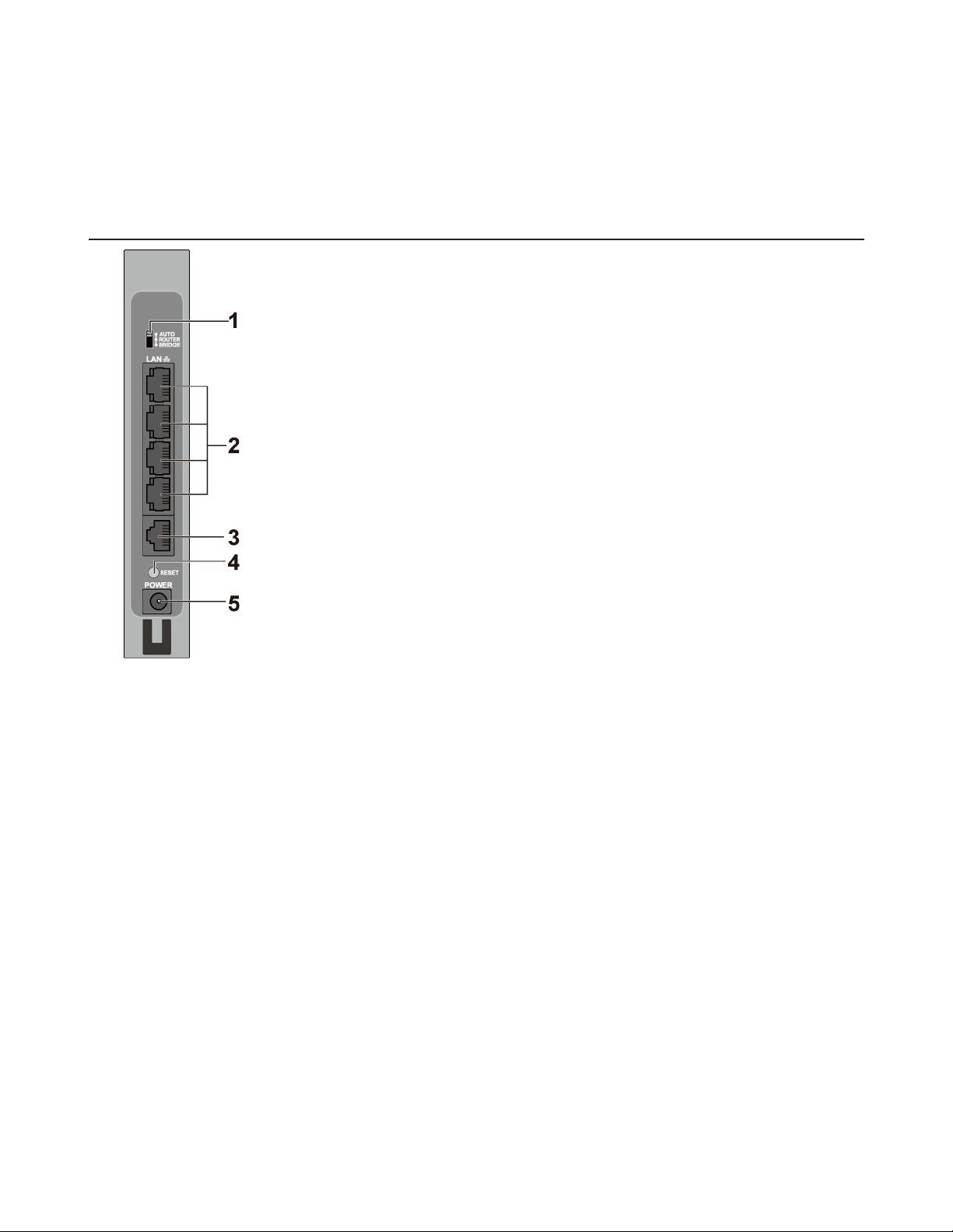
Back Panel
1 Mode Switch
This switch changes between router mode and bridge (access point) mode. Auto mode will enable or disable
router functionality automatically.
2 LAN Port
Connect your computer, hub, or other Ethernet devices to these ports. This switching hub supports 10 Mbps and
100 Mbps connections
3 Internet Port
10 Mbps, 100 Mbps, and 1000 Mbps connections are supported.
Note: In bridge mode, the Internet port becomes a regular LAN port that supports also 1000 Mbps, for a total of 5
usable LAN ports.
4 Reset Button
To reset all settings, hold down this button until the power/diag LED turns amber (about 3 seconds). The power
must be on for this to work.
5 DC Connector
Connect the included AC adapter here.
9
Page 10
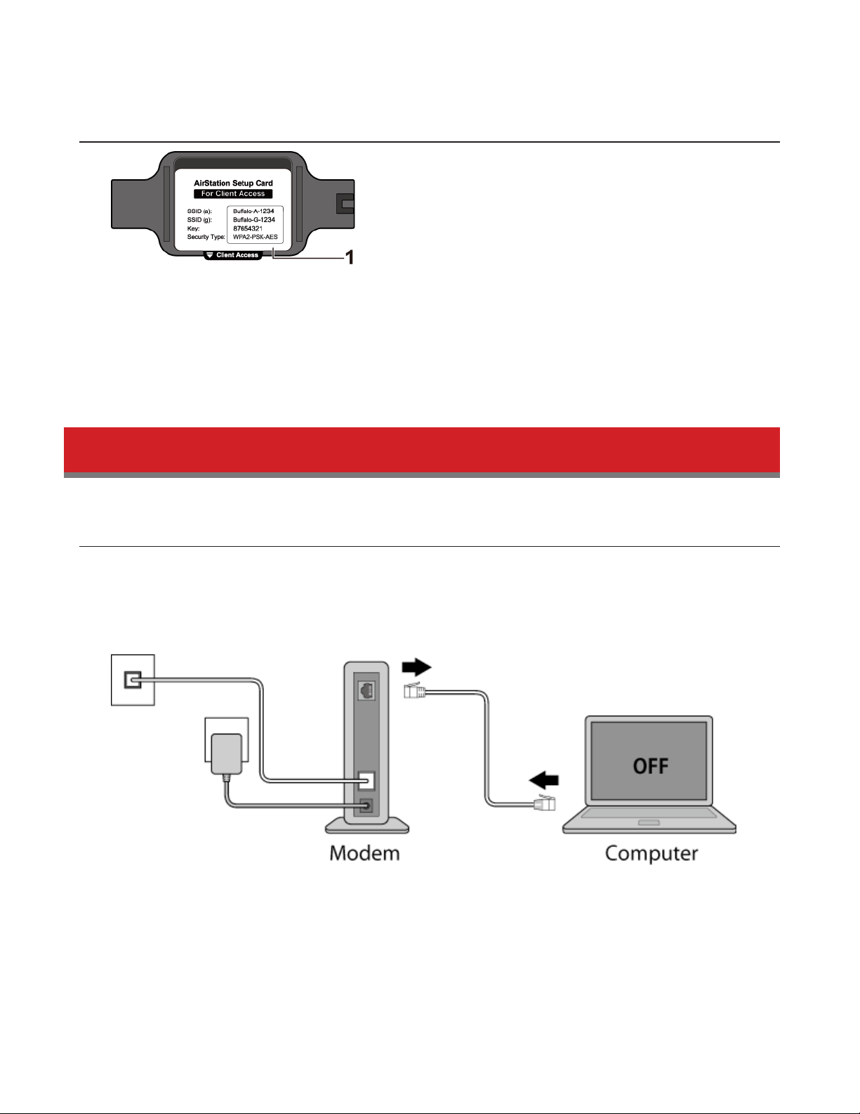
Bottom
1 Setup Card Slot
This is the slot where the AirStation setup card is stored. The initial settings for the username, password, SSID, and
encryption type are provided on the card.
How to Set Up AirStation for the First Time
Connect to a PC and Power On
To configure your AirStation, follow the procedure below.
1 Verify that you can connect to the Internet without the AirStation, then turn off your modem and computer.
2 Unplug the LAN cable which connects your computer and modem.
10
Page 11
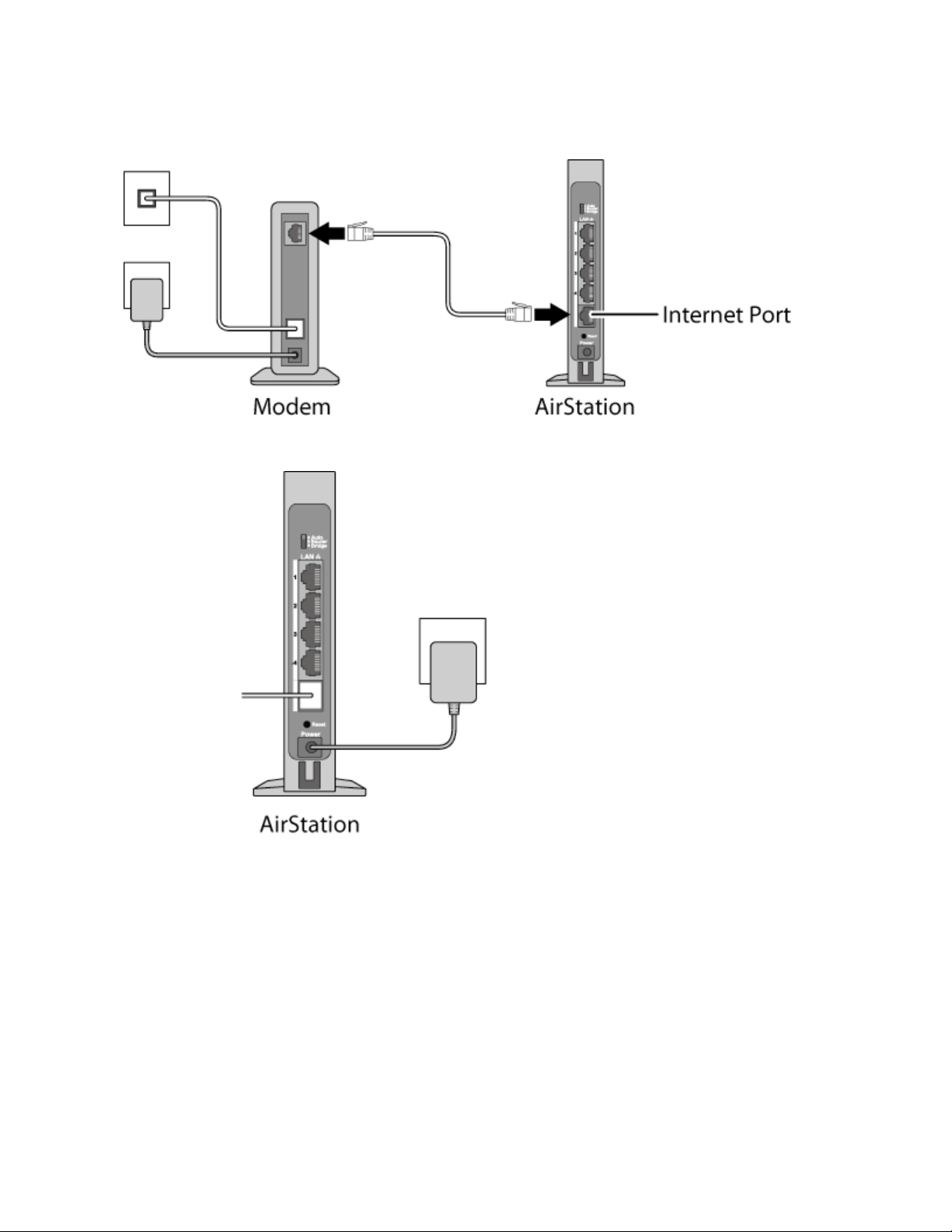
3 Confirm that the mode switch is in the “Auto” position. Plug one end of the LAN cable into your modem and the
other end to the AirStation’s Internet (WAN) port. Turn on the modem.
4 Turn on the AirStation and wait one minute.
11
Page 12
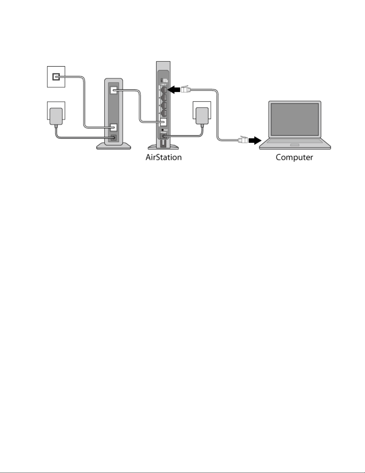
5 If using a wired LAN, connect the AirStation LAN port and computer using a LAN cable.
If using a wireless LAN, connect the computer to the wireless LAN as described in Chapter 3.
6 Once your computer has booted, the AirStation’s LEDs should be lit as described below:
Power/Diag: Lit green.
Wireless: Lit green.
Router: Lit green.
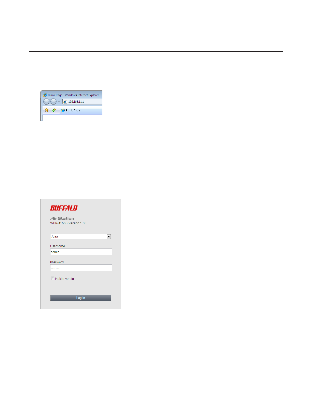
7 Launch a web browser. If the home screen is displayed, setup is complete.
If username and password fields are displayed, enter “admin” for the username and “password” for the password,
then click Log In. Step through the wizard to complete setup.
You’ve completed the initial setup of your AirStation.
12
Page 13
Opening Settings
To configure the AirStation, log in to Settings as shown below.
1 Launch a web browser.
2 Enter the AirStation’s LAN-side IP address in the address field and press the enter key.
Notes:
• The AirStation’s default LAN-side IP address depends on the mode.
• In router mode: 192.168.11.1
• In bridge (access point) mode: 192.168.11.100
• In wireless bridge mode: 192.168.11.100
If the mode switch is set to Auto and the AirStation is in bridge (access point) mode, the AirStation’s IP address is
assigned by an external DHCP server.
• If you changed the IP address of the AirStation, then use the new IP address.
3 Enter “admin” for the username and “password” for the password, then click Log In.
Note: If you forget your password, hold down the reset button to initialize all settings. Note that all other settings
will also revert to their default values.
13
Page 14
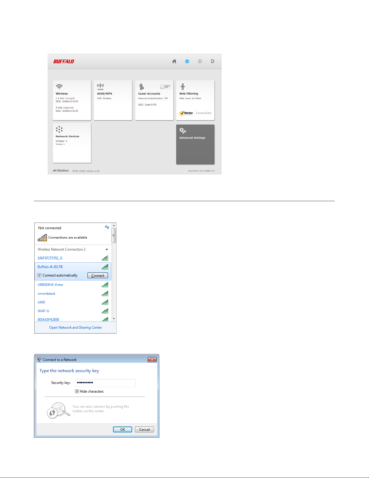
4 This is the home page of Settings, where most AirStation settings can be configured.
Connect Your Wireless Devices
For each wireless device that you want to connect to the network, use the device’s built-in software to search for
available networks. Find your SSID (the name of your wireless network) on the list of detected networks and select it.
Enter the passphrase for the network and you’ll be connected. Repeat for any additional wireless client devices that you
want to connect.
14
Page 15
Chapter 2 - Settings
Settings is the configuration GUI for the AirStation. You can configure all settings for the AirStation from here.
Easy Admin
Home
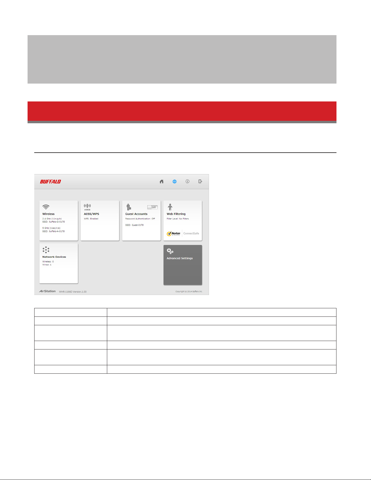
When you first open Settings, the Easy Admin page is shown. From this page you can easily configure common settings.
The examples below assume the AirStation is in router mode.
Wireless Displays current wireless status. Click the panel to configure wireless settings.
AOSS/WPS Displays current AOSS/WPS status. Click the panel to run AOSS/WPS.
Guest Accounts
Web Filtering Displays current content filter status. Click the panel to configure web filtering.
Network Devices
Advanced Settings Click the panel to configure advanced settings.
Displays current guest accounts status. Click the slider to turn guest accounts on or off.
Click the panel to configure guest accounts settings.
Displays the number of devices connected to the network. Click the panel to check each
device’s status.
15
Page 16
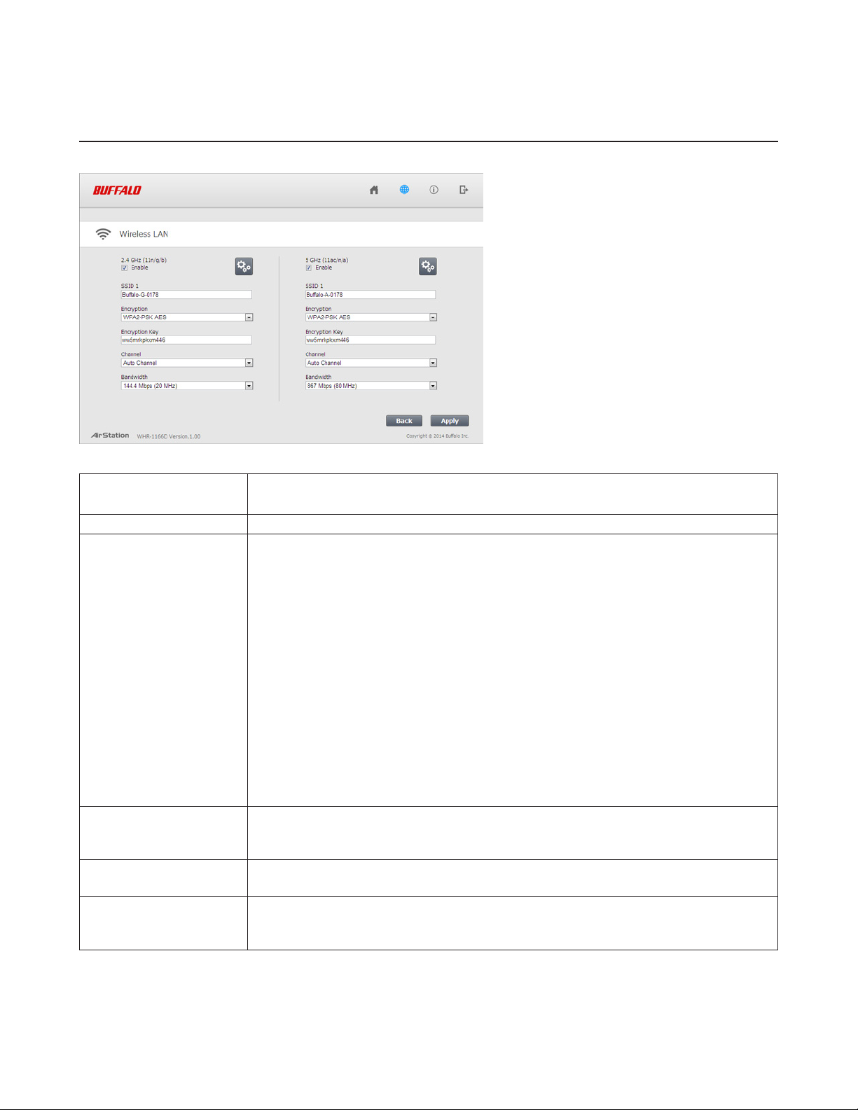
Wireless
Configure basic wireless settings here.
2.4 GHz (11n/g/b)
5 GHz (11ac/n/a)
SSID 1 Each SSID may contain up to 32 alphanumeric characters.
Encryption
Encryption Key
Channel
Bandwidth
You may enable or disable either wireless frequency range independently. If both
wireless radios are disabled, the AirStation will not communicate wirelessly.
The following types of encryption are available:
WPA2-PSK AES
WPA2 authentication with AES encryption is the best system available. Highly
recommended if all your wireless clients support it.
WPA-PSK AES
WPA authentication with AES encryption is an older system, but still secure.
WPA/WPA2-mixed PSK AES
For maximum compatibility, this system allows any combination of WPA, WPA2, and AES.
This encryption system works with most older clients but is not very secure.
No Encryption
No encryption means that anyone can log in to your wireless network, snoop on your
wireless traffic, and use your bandwidth. Not recommended for most users.
Note: To use WEP encryption, navigate to Wireless - 2.4 GHz (or 5 GHz) - Encrypt Wireless
Data and select WEP.
The encryption key is like the “password” for your wireless network. It may contain 8 to
63 case-sensitive alphanumeric characters (ASCII) or 64 hexadecimal characters (0-9 and
a-f, not case-sensitive).
For best results, select Auto Channel. The AirStation will seek and use the clearest
channel automatically. Alternately, you may choose a wireless channel manually.
In rural areas with little wireless traffic, a larger bandwidth setting may improve wireless
performance significantly. However, if you are in an urban area with much wireless traffic
and interference, the default bandwidth is recommended.
16
Page 17
AOSS/WPS
The following window appears when you click the panel. Click OK to start AOSS/WPS.
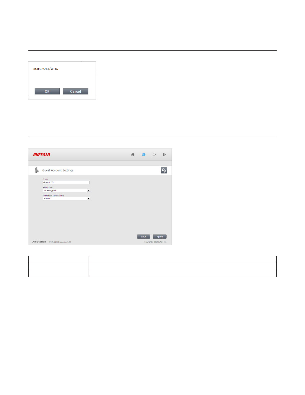
Guest Accounts
Configure guest account settings here.
SSID The SSID for the guest accounts may contain up to 32 alphanumeric characters.
Encryption Select an encryption mode for the guest accounts.
Permitted Access Time This is the amount of time that guests will be permitted to access the Internet.
17
Page 18
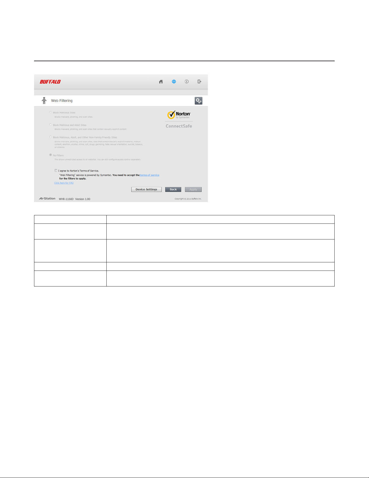
Web Filtering
Configure web filtering. This is available in router mode only.
Block Malicious Sites Blocks malware, phishing, and scam sites.
Block Malicious and
Adult Sites
Block Malicious, Adult,
and Other Non-Family
Friendly Sites
No Filters This allows unrestricted access to all websites.
I agree to Norton’s
Terms of Service
Blocks malware, phishing, and sites that contain sexually explicit content.
Blocks malware, phishing, and scam sites, sites that contain sexually explicit material,
mature content, abortion, alcohol, crime, cult, drugs, gambling, hate, sexual orientation,
suicide, tobacco, and violence.
Web filtering is provided by Symantec Corporation. To enable, you must accept the
terms of service.
Norton ConnectSafe must be activated by the customer. Use of Norton ConnectSafe is subject to the terms of service
found at https://dns.norton.com/dnsweb/terms.do
.
18
Page 19

Network Devices
Check the status of each device connected to the network. This is available in router mode only.
Displays the IP address of each device connected to this product.
Displays the devices connected to the AirStation.
Click the appropriate icon to open each device’s settings.
Click the icon to send a Wake-on-LAN packet to the device.
19
Page 20
Advanced Settings
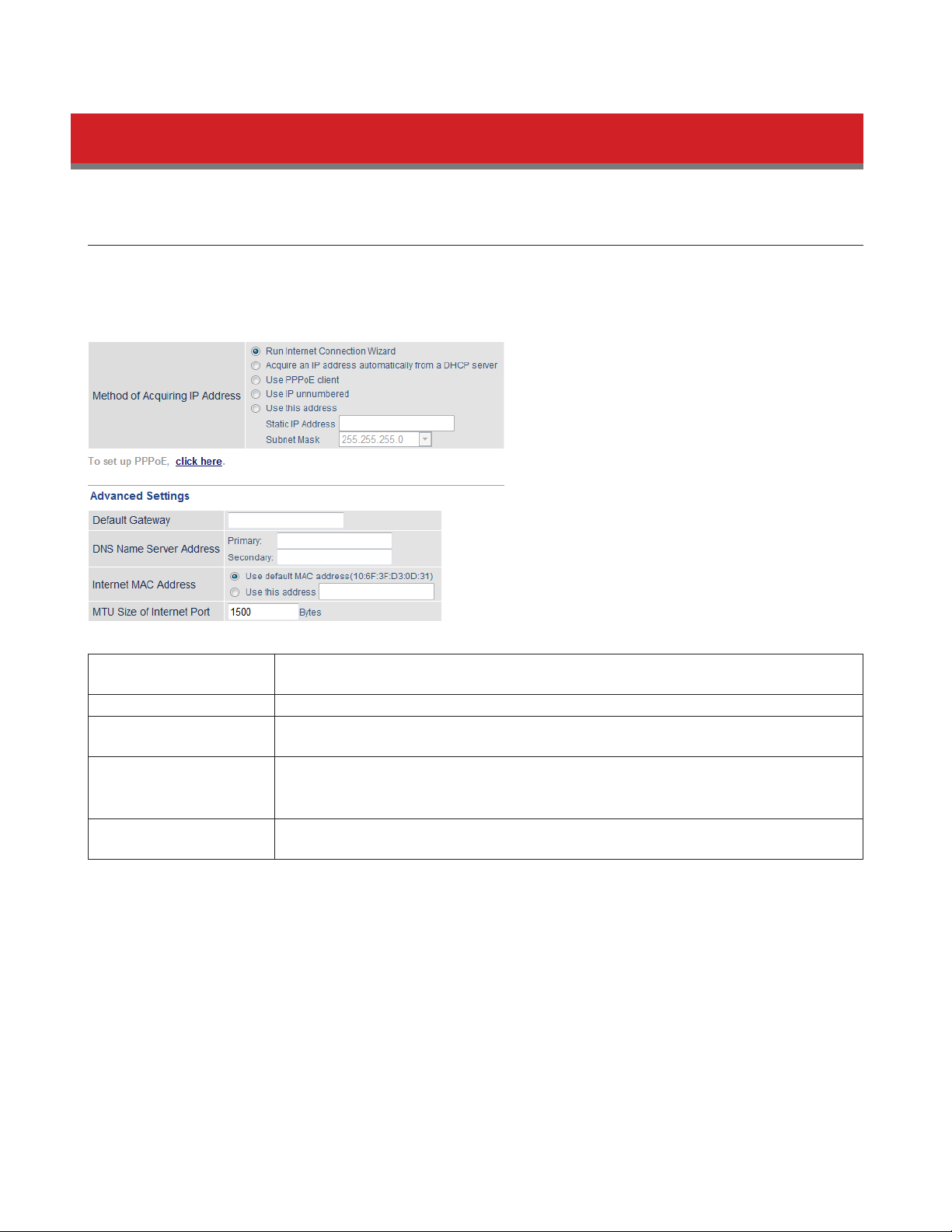
Internet
Configure the WAN-side port (Internet port) here.
Internet - Internet (Router Mode Only)
Method of Acquiring IP
Address
Default Gateway Configure an IP address for the default gateway.
DNS Name Server
Address
Internet MAC Address
MTU Size of Internet
Port
Specify how the WAN-side IP address is obtained.
Specify IP addresses for the DNS server.
You may use the default MAC address or specify one manually.
Note: Configuring an improper MAC address may make the AirStation unusable. Do not
change the MAC address unless you know what you’re doing!
Configure the MTU value of the Internet port. Values of 578 to 1500 bytes may be
entered.
20
Page 21
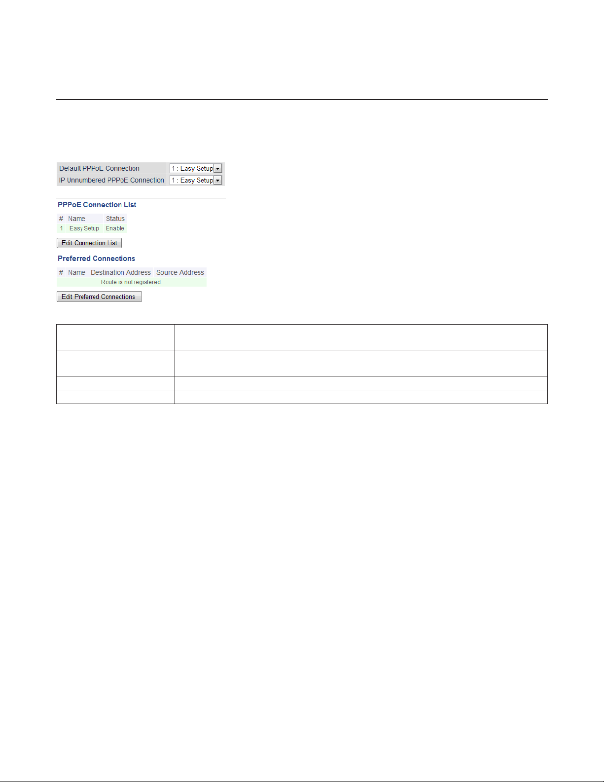
PPPoE
Configure PPPoE settings here.
Internet - PPPoE (Router Mode Only)
Default PPPoE
Connection
IP Unnumbered PPPoE
Connection
PPPoE Connection List Edit PPPoE destination. You can register up to 5 sessions.
Edit Connection List Click this button to edit destination settings.
If you have registered multiple connection destinations in the PPPoE Connection List,
connection destinations selected here have priority.
Select the destination from the PPPoE Connection List to be used when Use IP
Unnumbered is chosen as the method of acquiring IP address.
21
Page 22

This is displayed when Edit Connection List is clicked.
Name of Connection
Enter the name to identify the connected destination. You may enter up to 32
alphanumerical characters and symbols.
Username
Enter the username specified by your ISP for PPPoE certification. You may enter up to 64
alphanumerical characters and symbols.
Password
Enter the password specified by your ISP for PPPoE certification. You may enter up to 64
alphanumerical characters and symbols.
Service Name
Fill in this field only if your ISP specifies a service name. Leave blank otherwise. You may
enter up to 64 alphanumerical characters and symbols.
Connection Type
Specifies the timing for the AirStation to connect to your provider.
PPPoE Connection
Preferred Connections Displays information you have set regarding to the connection destination route.
Edit Preferred
Connections
Preferred PPPoE
Connection
Automatic Disconnection
Set time to disconnect after communication is stopped when the connection method is
set to Connection on Demand or Manual. You can enter up to 1440 minutes.
Authentication
Configure an authentication method with an ISP.
MTU Size
Configure the MTU (maximum transmission unit) size for PPPoE. Values of 578 to 1492
bytes may be entered.
MRU Size
Configure MRU (maximum receive unit) for PPPoE. Values of 578 to 1492 may be
entered.
Keepalive
If keepalive is enabled, the AirStation will issue an LCP echo request once a minute in
order to maintain the connection with the PPPoE. If the server does not respond for
more than 6 minutes, the line is recognized as disconnected and the AirStation will
terminate the connection. Disabled by default.
Click to edit the connection destination route settings.
Click Edit Preferred Connections to display.
Name
The destination to connect by PPPoE if Destination Address and Source Address match.
Select the destination registered to the PPPoE Connection List.
Destination Address
When communicating to this address, the AirStation will communicate with Name.
Source Address
When communicating from this address, the AirStation will communicate with Name.
22
Page 23
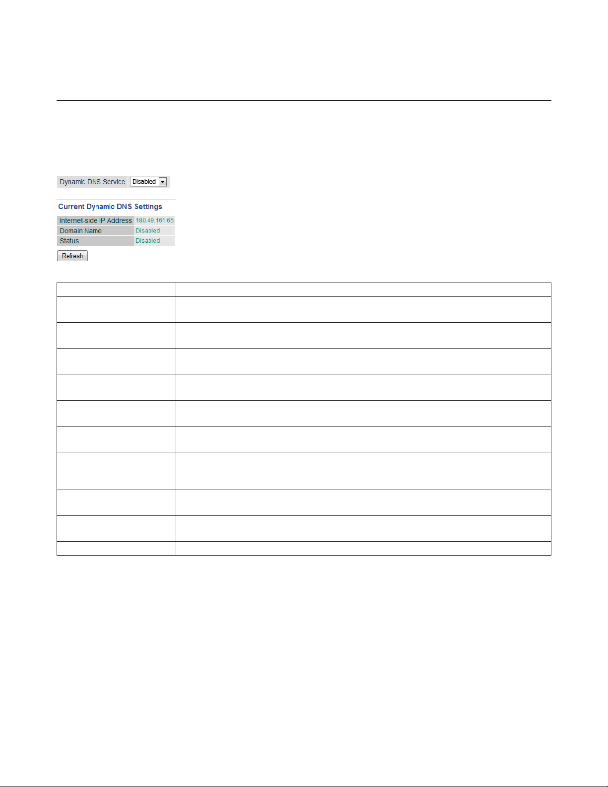
Dynamic DNS
Configure dynamic DNS settings here. Many settings are only available when the appropriate dynamic DNS service is
enabled.
Internet - Dynamic DNS (Router Mode Only)
Dynamic DNS Service Select a supported dynamic DNS provider (DynDNS or TZO).
Username
Password
Hostname
Email Address
TZO Key
Domain Name
IP Address Update
Period
Internet-side IP Address
Domain Name
Status Displays the status of the dynamic DNS service.
Enter the dynamic DNS username. You may enter up to 64 alphanumerical characters
and symbols.
Enter the dynamic DNS password. You may enter up to 64 alphanumerical characters
and symbols.
Enter the dynamic DNS hostname. You may enter up to 255 alphanumerical characters,
hyphens, and periods.
Enter the email address which is registered to the dynamic DNS service. You may enter
up to 64 alphanumerical characters and symbols.
Enter the TZO key which is registered to the dynamic DNS service. You may enter up to
64 alphanumerical characters and symbols.
Enter the domain name which is registered to the dynamic DNS service. You may enter
up to 255 alphanumerical characters, hyphens, and periods.
Specifies the period to notify the dynamic DNS service provider of the current IP
address. For DynDNS, set it between 0 and 35 days. For TZO, set it between 0 and 99
days. If 0 (zero) days is set, no periodic update is performed.
The WAN-side IP address of the AirStation’s Internet port. This address is sent to the
dynamic DNS service provider.
The domain name assigned by the dynamic DNS service provider. The AirStation can be
accessed from the Internet using this domain name.
23
Page 24
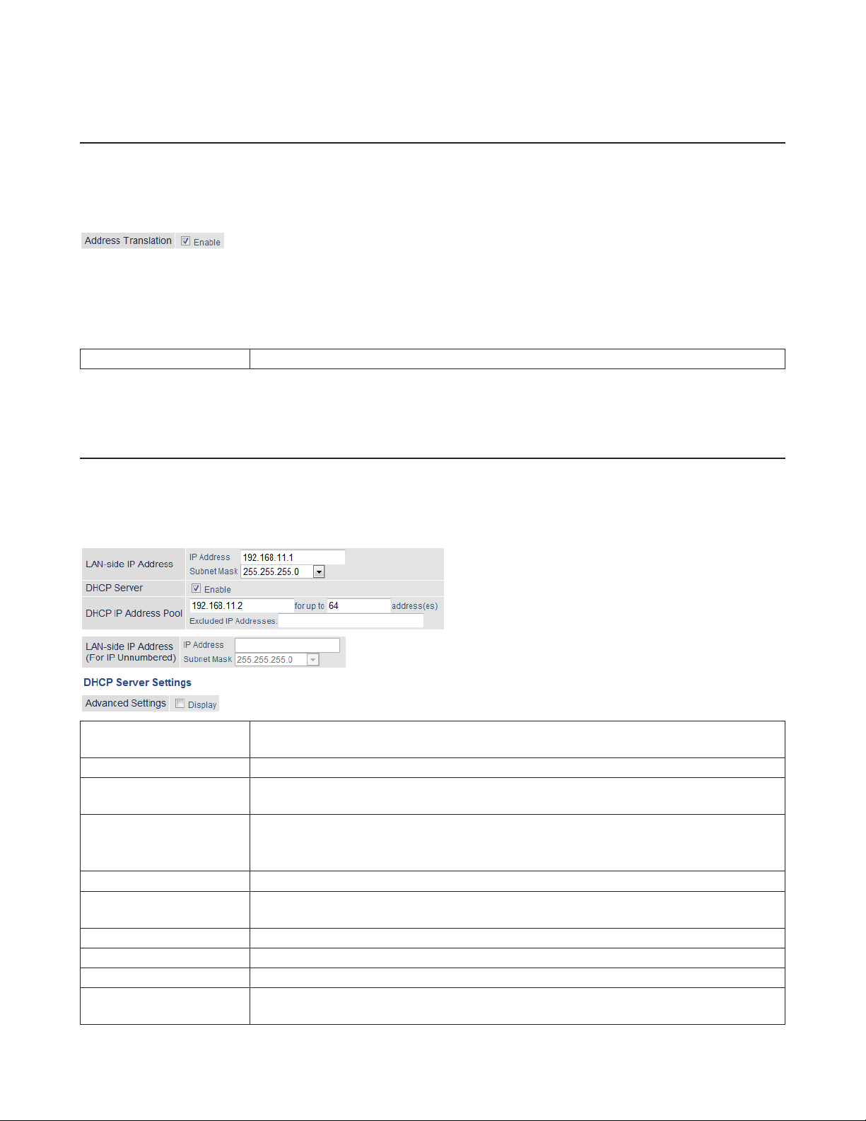
NAT
Configure network address translation settings here. This enables LAN-side devices to communicate with the Internet.
Internet - NAT (Router Mode Only)
Address Translation Enable to use network address translation.
LAN
Configure LAN-side and DHCP server settings.
LAN - LAN
LAN-side IP Address
DHCP Server Enable or disable the DHCP server, which assigns LAN-side IP addresses automatically.
DHCP IP Address Pool
LAN-side IP Address (For
IP Unnumbered)
Advanced Settings Check Display to display DHCP server advanced settings options.
Lease Period
Default Gateway Set the default gateway IP address for the DHCP server to issue to clients.
DNS Servers Set the DNS server IP address for the DHCP server to issue to clients.
WINS Server Set the WINS server IP address for the DHCP server to issue to clients.
Domain Name
By default, the LAN-side IP address is 192.168.11.1 with subnet mask 255.255.255.0. You
may change it here.
Configure the range of IP addresses to be assigned by the DHCP server and IP addresses
to be excluded from that range. Values from 1-256 may be entered.
Set an IP unnumbered LAN-side IP address.
Note: A PC with a normal LAN-side IP address and a PC with an IP unnumbered IP
address cannot communicate with each other.
Set the effective period for IP addresses assigned by the DHCP server. Up to 999 hours
may be entered.
Set the domain name for the DHCP server to issue to clients. You may enter up to 64
alphanumerical characters, hyphens, and periods.
24
Page 25
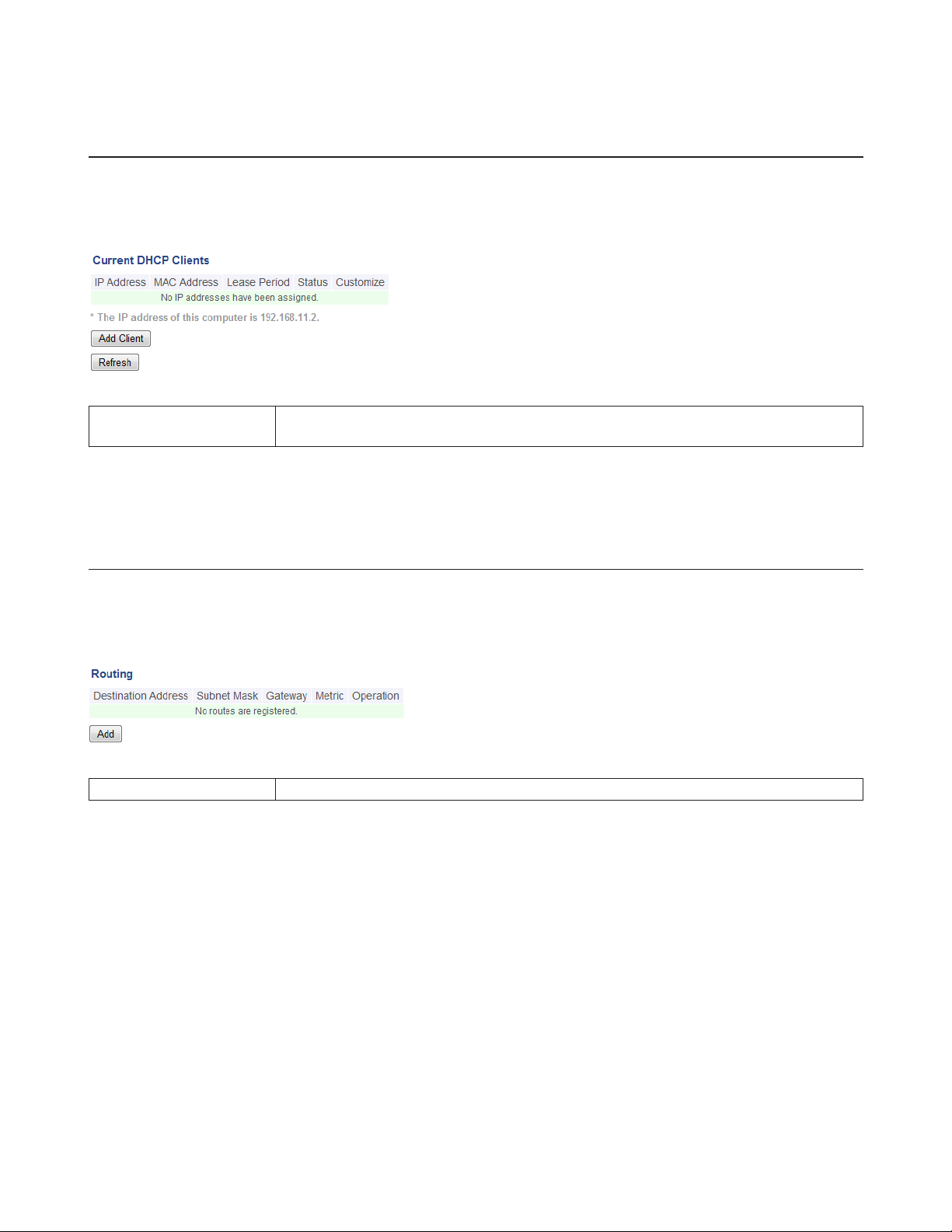
DHCP Lease
Configure DHCP exceptions here.
LAN - DHCP Lease (Router Mode Only)
Current DHCP Clients
Displays information for current leases. An IP address which is leased automatically can
be changed to manual leasing by clicking Add Client.
Routing
Configure the AirStation’s IP communication route here.
LAN - Routing
Routing Manual entries will appear here after being added.
25
Page 26

2.4 GHz/5 GHz
Configure basic wireless settings from here.
Wireless - 2.4 GHz or 5 GHz
Wireless
Determines whether to allow wireless communication. If this is unchecked, no wireless
connections will be allowed.
26
Page 27

Wireless Channel
High-Speed Mode
Broadcast SSID
SSID 1
SSID 2
SSID Isolation
Wireless Authentication
Encrypt Wireless Data
WPA-PSK (Pre-shared
Key)
Key Renewal Interval Set the update interval for the encryption key between 0 and 1440 (minutes).
WEP Encryption Key
Settings
Multicast Rate Set the communication speed of multicast packets.
DTIM Period
Sets a channel (a range of frequencies) for wireless connections. With Auto Channel
selected, the AirStation will automatically use the best available channel.
Configure the bandwidth for wireless communication. To increase communication rate,
set the bandwidth to 80 or 40 MHz.
If Allow is checked, then the AirStation will respond to SSID searches from wireless
devices by broadcasting its SSID. If Allow is unchecked, the AirStation ignores SSID
searches from wireless devices.
Enable or disable the main SSID (SSID 1) and sub SSID (SSID 2).
Enable to make wireless devices connected to the specified SSID be able to
communicate only with the Internet-side.
Select an authentication method for SSID 1 from below:
WPA/WPA2-mixed mode PSK
Allows the authentication compatible with WPA-PSK and WPA2-PSK at the same time.
WPA2-PSK
Allows the authentication compatible with WPA2 (IEEE 802.11i).
WPA-PSK
Allows the authentication compatible with WPA (Wi-Fi Protected Access).
No authentication
Connect to wireless clients without any authentication method.
You may use any of the following types of encryption:
AES
AES uses a pre-shared key to communicate with wireless devices. It is faster and more
secure than TKIP. AES can be selected only when WPA-PSK or WPA2-PSK is selected for
wireless authentication.
WEP
WEP is a common encryption method supported by most devices. WEP can only be
selected when wireless authentication is set to No Authentication. Note that WEP’s
encryption is weak, and networks protected with WEP are not much more secure than
those with no encryption at all. Not recommended for anyone with private data that
needs to be kept secure.
No encryption
Data is transmitted without encryption. With this setting, anyone within range can
connect to your wireless network and might be able to access data on the network. Not
recommended for anyone with private data that needs to be kept secure. No Encryption
can be selected only when No Authentication is selected for wireless authentication.
A pre-shared key or passphrase is the password for your wireless connections. There are
two different formats for a pre-shared key. Use 8 to 63 alphanumeric characters (casesensitive) for an ASCII passphrase, or use 64 alphanumeric characters (0 to 9 and a to f,
not case-sensitive) for a hexadecimal passphrase.
A WEP encryption key (passphrase) may have any of four different formats. An
ASCII passphrase may use either 5 or 13 alphanumeric characters (case-sensitive). A
hexadecimal passphrase may use either 10 or 26 alphanumeric characters (0 to 9 and a
to f, not case-sensitive).
Set the beacon responding interval (1 -255) for which the AirStation responds to a
wireless device. This setting is effective only when power management is enabled for
the wireless device.
27
Page 28

If enabled, the wireless client isolation blocks communication between wireless devices
Wireless Client Isolation
Output Power
(5 GHz Only)
WMM Settings Check Display to set priorities only for a specific communication.
WMM-EDCA Parameters
connected to the AirStation. Wireless devices will be able to connect to the Internet
but not with each other. Devices that are connected to the AirStation with wired
connections will still be able to connect to wireless devices normally.
This sets the output of the wireless signal. Because the wireless transmission output and
signal distance range are nearly proportional, when the wireless transmission output is
reduced, the signal distance range also becomes shorter.
You don’t usually need to change these settings. Using the default settings is
recommended.
Priority
The following priorities may be applied to individual transmission packets: (Highest) 8,
(High) 4, (Normal) 2, and (Low) 1. From the queue, these packets are processed in order
of priority.
CWmin, CWmax
The maximum and minimum value of the contention window. The contention window is
used in the frame collision avoidance structure performed in IEEE802.11, and generally,
the smaller the value in the window, the higher the probability that the queue obtains
the right to send.
AIFSN
The interval to send frames. The unit of the AIFSN is a slot, just as the window defined
by CWmin and CWmax is. The smaller the interval of sending frames, the faster the
algorithm can restart. As a result, the priority of the queue is higher.
TXOP Limit
The period of time that the queue can use after obtaining the right to send. The unit is
32 ms. The longer this time, the more frames can be sent per right to send. However, the
queue may interfere with other packet transmissions. If TXOP Limit is set to 0 (zero), only
one frame can be sent per right to send.
28
Page 29

WPS
WPS (Wi-Fi Protected Setup) enables users to easily configure wireless networks and add new devices.
Wireless - WPS
WPS Enable to use WPS automatic configuration.
External Registrar
AirStation PIN
WPS PIN Enter the PIN code for the other wireless device and click OK.
WPS Status
Enable to accept configure requests from other WPS devices.
Note: Configure requests will not be accepted if AOSS is in use.
Displays the PIN code of the AirStation. Clicking Generate PIN will generate a new PIN
code. This code can be entered into other wireless devices that support WPS.
Displays configured if all available wireless bands are configured. Displays unconfigured if
at least one wireless band is unconfigured.
AOSS
AOSS (AirStation One-Touch Secure System) is a system for easily configuring a secure wireless home network. It was
developed by Buffalo.
29
Page 30

Wireless - AOSS
Exclusive SSID for WEP
You may allow a separate SSID specifically for WEP connections. If Stop is selected,
then clients will not be able to connect with WEP.
30
Page 31

Allow WEP for Game
Consoles Only
AOSS Button on the
AirStation Unit
Current Security
Information
Random Click to enter random values for SSID, encryption key, and other settings.
KEY Base
Reset
AOSS Client Information
This allows game consoles that only support WEP to connect to the network.
If Enable is unchecked, only WPS runs when you press the button.
Displays the encryption type, SSID, and encryption key configured by AOSS.
Click to return the SSID, encryption key, and other wireless settings to the values on the
case sticker.
Click to return the SSID, encryption key, and other wireless settings to their previous
values.
Displays the information of the clients connected to this product via AOSS and
communicating with this product wirelessly.
Name
Displays the name of the clients.
MAC Address
Displays the MAC address of the clients.
Encryption Type
Displays the encryption type the clients can use.
Wireless
Displays current connection method.
Connection Settings
Displays current connection settings status.
31
Page 32

MAC Filtering
Restrict access to specific wireless devices here.
Wireless - MAC Filtering
Enforce MAC Filtering Enable to restrict wireless connections to devices with registered MAC addresses.
Registration List
Edit Registration List Adds a wireless device to the list of permitted devices.
Enter MAC Addresses
Connected Client’s List Display the list of all MAC addresses of wireless devices connected to the AirStation.
Displays the MAC addresses of registered devices which are permitted to connect
wirelessly.
Enter a MAC address of a wireless device to permit to connect to the AirStation. Click
Register to add that MAC address to the list.
Multicast Control
Configure restrictions on unnecessary multicast packets sent to the wireless LAN port here.
Wireless - Multicast Control
Snooping
Multicast Aging Time
If enabled, snooping supervises multicast administrative packets such as IGMP and
restricts unnecessary multicast transfers to wired or wireless ports.
Set the time to hold the data from multicast snooping in the range of 1 to 3600
(seconds). Enter a value bigger than the IGMP/MLD query interval.
32
Page 33

Guest Accounts
Configure the AirStation’s guest accounts here.
Wireless - Guest Accounts
Guest Accounts Enable or disable the guest accounts.
Guest User
Authentication
Guest Account LAN IP
Address
Guest Account DHCP
Server
Permitted Access Time Set the time frame for Internet access for the guest accounts.
SSID This sets the SSID for the guest accounts.
Wireless Authentication This sets whether wireless authentication is performed for the guest accounts.
Wireless Encryption This sets the wireless encryption system for the guest accounts.
WPA-PSK (Pre-shared
Key)
Edit Guests Click to register a user to use the guest accounts.
Username Enter a name for the guest user.
Password Enter a password for the guest user.
This sets whether authentication is performed for guest users.
This sets the LAN-side IP address for the guest accounts.
This sets whether IP addresses are automatically assigned for devices connected to the
guest accounts.
This sets the wireless encryption key for the guest accounts.
33
Page 34

WB
Configure WB (wireless bridge) here. This function is only available when the AirStation is in bridge mode.
Wireless - WB
WB If enabled, the AirStation can connect to the wireless master. Disabled by default.
Connection Type
Connection Status Displays the connection status with the master.
SSID Specify an SSID to connect to the master manually.
Search Click to search for a master.
Authentication Specify the authentication method used to connect to the master.
Encryption Specify the encryption method used to connect to the master.
Select the connection method to connect to the master. You may use AOSS or WPS to
connect push-button style, or specify an SSID to configure manually.
34
Page 35

Firewall
Configure the AirStation’s firewall here.
Security - Firewall (Router Mode Only)
Enable to use any of the quick filters. Preconfigured quick filters include:
Prohibit NBT and Microsoft-DS routing
Enabling this blocks communication using these protocols from the WAN side to the
LAN side or from the LAN side to the Internet. You can configure this with PPPoE if you
select Use PPPoE client or Use IP Unnumbered for the method of acquiring IP Address, or if
Easy Setup identified a PPPoE connection during setup.
Reject ident requests
Enabling this option will answer ident requests from the Internet side with
Basic Rules
corresponding rejection packets. Enable this option if you experienced slow transfer
speeds for network applications such as email, FTP, and web browsing. If you have
configured transfer of ident requests to the LAN-side computer in the address
translation settings (DMZ or TCP port 113), then that setting has higher priority, and
overrides this setting.
Block ping from Internet
If this is enabled, the AirStation will not respond to pings from the Internet side. You
can configure this with PPPoE if you select Use PPPoE client or Use IP Unnumbered for the
method of acquiring an IP address, or if Easy Setup identified a PPPoE connection during
setup.
35
Page 36

IP Filter
Create and edit IP filters here.
Security - IP Filter (Router Mode Only)
Action Specify how to process target packets.
Direction Specify the transmission direction of target packets.
IP Address Specify the sender’s IP address and receiver’s IP address of the target packets.
Protocol Select a protocol for target transmission packet.
IP Filter Display the list of IP filters which have been registered.
VPN Passthrough
Configure IPv6 passthrough, PPPoE passthrough, and PPTP passthrough here.
Security - VPN Passthrough (Router Mode Only)
IPv6 Passthrough Enable to use IPv6 passthrough for address translation.
Enable to use PPPoE bridging. PPPoE bridging lets you automatically obtain an IP
PPPoE Passthrough
PPTP Passthrough Enable to use PPTP passthrough for address translation.
address from your provider for your LAN-side computer using the PPPoE protocol
because PPPoE packets can pass between the Internet and LAN.
36
Page 37

Port Forwarding
Configure port translation here.
Security - Port Forwarding (Router Mode Only)
Specify a group name for a new rule to belong to. Select New Group and enter the new
Group
Internet-side IP Address Enter the Internet-side IP address (before translation) for the port translation table entry.
Protocol Select the Internet-side protocol (before translation) for the port translation table entry.
LAN-side IP Address Enter the LAN-side IP address (after translation) for the port translation table entry.
LAN-side Port
Forwarded Ports Shows current entries in the port translation table.
group name in the Group Name field to create a new group. A group name can include
up to 16 alphanumeric characters.
Select the LAN-side (after translation) port number (1 - 65535) for the port translation
table entry.
37
Page 38

DMZ
Configure a destination for packets that don’t have a LAN-side destination.
Security - DMZ (Router Mode Only)
Enter the IP address of the destination for packets not routed by port translation table to
Add IP Address to DMZ
be forwarded.
Note: RIP protocol packets (UDP port number 520) will not be forwarded.
UPnP
Configure UPnP (Universal Plug and Play) here.
Security - UPnP (Router Mode Only)
UPnP Enable or disable Universal Plug and Play.
38
Page 39

Web Filtering
Security - Web Filtering (Router Mode Only)
Norton ConnectSafe must be activated by the customer. Use of Norton ConnectSafe is subject to the terms of service
found at https://dns.norton.com/dnsweb/terms.do .
Filter Level Select the filter level.
Websites Excluded from
Filter
Computers Excluded
from Filter
Specify a list of websites that will be unaffected by the web filter. Click Add and enter any
website (up to 20 are allowed). You can edit or delete entered entries.
Set a list of computers on the network that will be unaffected by the web filter. Click
Add and enter a computer’s MAC address (up to 20 are allowed). You can edit or delete
entered entries.
39
Page 40

Access Control
Security - Access Control (Router Mode Only)
Access Control Check to enable access control. Click Add to configure the schedule.
Add Access Control
Permitted Access Time Displays the time that the computer is allowed to access to the Internet.
Register Configure the schedule, then click Edit Permitted Access Time. The schedule is registered.
Enter the computer’s MAC address in the Target Computer field. You can add up to 20
network computers.
QoS
Configure QoS (quality of service) settings here.
Applications - QoS (Router Mode Only)
QoS Enable or disable QoS.
Upload Bandwidth
Enable Enable or disable this entry.
Application Name
Protocol Select either TCP or UDP.
Destination Port
Specify the upstream bandwidth in kbps from the AirStation to the Internet side. Set the
actual value for the upstream bandwidth.
Enter an application name. Names may use up to 32 alphanumerical characters, double
or single tick marks (“’), quotation marks (“), and semicolons (;).
Specifies a destination port from 1 - 65535. If this field is empty, a random port is
selected.
40
Page 41

Priority
Select high, medium, or low. If packets do not qualify for classification as a type on the
list, then their priority is treated as a level between medium and low.
eco Mode
Configure eco Mode from this screen.
Applications - eco Mode
Power Saving
Custom Mode Individual power saving elements may be configured for custom mode.
Weekly Schedule Graphically displays the configured schedule.
Schedule Entry Configure operational mode for time periods in the weekly schedule.
Enable to set the power saving schedule. If eco Mode is enabled, AOSS will function only
when the AirStation is in normal operating mode.
41
Page 42

System
Configure basic AirStation settings here.
Admin - System
AirStation Name
Administrator The name of the administrator account is “admin”.
Administrator Password
Prohibit configuration
from wireless LAN
Prohibit configuration
from wired LAN
Permit configuration
from wired Internet
Permitted IP address
Enter a name for the AirStation. Names may include up to 64 alphanumeric characters
and hyphens (-).
The administrator password may contain up to 8 alphanumeric characters and
underscores (_).
If enabled, prevents access to configuration interface from wirelessly connected devices
(only wired devices may configure).
If enabled, prevents access to configuration interface from wired devices (only wirelessly
connected devices may configure).
If enabled, allows access to configuration interface from network devices on the WAN
(Internet) side.
Displayed only if Internet-side configuration is enabled. Enter the IP address of a device
that is permitted to configure the AirStation remotely from the WAN (Internet) side.
42
Page 43

Permitted Port
NTP Functionality Enable to use an NTP server.
NTP Server
Update Interval
Local Date You may manually set the date of the AirStation’s internal clock.
Local Time You may manually set the time of the AirStation’s internal clock.
Time Zone Specify the time zone (offset of Greenwich Mean Time) of the AirStation’s internal clock.
Displayed only if Internet-side configuration is enabled. Set a port number (1 - 65535) to
configure the AirStation from the WAN (Internet) side.
Enter the name of the NTP server as a hostname, hostname with domain name, or IP
address. Up to 255 alphanumeric characters, hyphens (-), and underscores (_) may be
used. The default is time.nist.gov.
How often will the AirStation check the NTP server for the correct time? Intervals of 1 24 hours may be set. The default is 24 hours.
Syslog Settings
You may transfer the AirStation’s logs to a syslog server.
Admin - Syslog Settings
Transfer Logs Enable to send logs to a syslog server.
Syslog Server
Logs Choose which logs will be transferred to the syslog server.
Detailed Logs Choose which detailed logs will be transferred to the syslog server.
Identify the syslog server by hostname, hostname with domain name, or IP address. You
may enter up to 255 alphanumeric characters and hyphens (-).
43
Page 44

Reset / Reboot
From this page you can save and restore the AirStation’s settings, initialize the AirStation, or reboot the AirStation.
Admin - Reset / Reboot
Select an operation.
Back up settings
Save this product’s settings to a file. Click Execute. You can encrypt the setting file by
checking Use Password and clicking Execute.
Operation
Restart Click it to restart the AirStation.
Restore settings
Restore this product’s settings from the setting file. Click Browse... and specify a setting
file, then click Execute. If the setting file is encrypted, check Use Password and click
Execute.
Initialize AirStation
This will return the AirStation to its factory default settings.
44
Page 45

Update Firmware
Update the AirStation’s firmware here.
Admin - Update Firmware
Firmware Version Displays the current firmware version of the AirStation.
Update Method
Firmware File Name
Specify a file on your PC updates from a firmware file stored on your computer. Automatic
update updates to the latest firmware automatically.
Click Browse... to navigate to the firmware file on your computer if Specify a file on your
PC is selected. You don’t need to specify the firmware location if you’re using Automatic
update. Click Update Firmware to update the firmware.
45
Page 46

System Information
View system information for the AirStation.
Status - System Information
Model Displays the product name of the AirStation and the firmware version.
AirStation Name Displays the name of the AirStation.
Hardware Mode Switch
Status
Mode Displays the AirStation’s current operational mode.
Internet Displays information about the Internet port.
LAN Displays information about the LAN port.
Wireless (5 GHz)
Wireless (2.4 GHz)
Guest Accounts Displays information about the guest accounts.
Web Filtering Displays the operating status of the web filter.
WB Displays the WB status.
eco Mode This indicates the operating status of eco Mode.
Displays the status of the AirStation’s mode switch.
Displays the wireless status.
46
Page 47

Logs
The AirStation’s logs are recorded here.
Status - Logs
Display logs Choose the types of logs to display.
Logs Displays the log information recorded in the AirStation.
Packets
View packet transfer information.
Status - Packets
Sent Displays the number of packets sent to the WAN, the LAN, and the wireless LAN.
Received Displays the number of packets received from the WAN, the LAN, and the wireless LAN.
47
Page 48

Ping
A ping test checks whether the AirStation can communicate with a specific network device.
Status - Ping
Destination Address
Enter the IP address or hostname of the device that you are testing communication with,
then click Execute. The result will be displayed below.
48
Page 49

Chapter 3 - Wireless
Wireless Options
You may use any of the following methods to connect devices to the AirStation wirelessly.
Manual Configuration
On your device, search for available networks and find the AirStation. If a password is required, enter the AirStation’s
encryption key.
WPS (Wi-Fi Protected Setup)
WPS is an automatic connection method created by the Wi-Fi Alliance. Two different versions of WPS are supported:
pushbutton and PIN. For pushbutton, start WPS on your client device, then press the AOSS button on the AirStation.
Alternately, if your wireless client has a WPS PIN, you may use the Client Manager to enter the PIN in the AirStation. With
either of these methods, a wireless connection will be established automatically within a couple of minutes.
Notes:
• WPS supports Windows 8.1, Windows 8, Windows 7, and Windows Vista (SP 2).
• Mac OS is not supported.
AOSS (AirStation One-Touch Secure System)
AOSS is a proprietary system by Buffalo that lets you set up a secure wireless connection with the push of a button. Press
your device’s and the AirStation’s AOSS buttons and a secure wireless connection will be configured automatically.
Notes:
• To use AOSS with a Windows PC, install Client Manager.
• To use AOSS with Mac, install AOSS Assistant.
49
Page 50

Advanced Wireless Configuration
Manual Configuration (SSID and Password)
1 Click the wireless icon.
2 Select your AirStation’s SSID from the list.
Note: Your AirStation’s default SSID and encryption key are on the setup card stored in the base of the AirStation.
3 Enter the AirStation’s encryption key.
4 The connection will be established.
Automatic Secure Setup (WPS)
1 Click the wireless icon.
2 Select your AirStation’s SSID from the list.
Note: Your AirStation’s default SSID is on the setup card stored in the base of the AirStation.
50
Page 51

3 Without entering a password, press the AOSS button on the AirStation.
Notes:
• WPS supports Windows 8.1, Windows 8, Windows 7, and Windows Vista Service Pack 2 only.
• Mac OS is not supported.
4 The connection will be established.
Automatic Secure Setup (AOSS)
1 Windows users should download Client Manager from Buffalo’s website and install it.
Mac users should download AOSS Assistant and install it.
2 Initiate AOSS from Client Manager or AOSS Assistant.
3 Press your AirStation’s AOSS button.
4 The connection will be established.
51
Page 52

Chapter 4 - Utilities
How to Download Utilities
You can download utilities for your AirStation from Buffalo’s website.
http://d.buffalo.jp/whr-1166d/
52
Page 53

List of Utilities with Description of Each
AirStation Configuration Tool
You can enter AirStation’s Settings and change its IP address with this tool.
Compatible with:
WIndows 8.1, Windows 8, Windows 7, Windows Vista, Windows XP
OS X 10.9, 10.8, 10.7, 10.6, 10.5, 10.4
53
Page 54

Client Manager
Use this software to let your Windows PC connect to the AirStation with AOSS.
Client Manager V supports Windows 8.1, Windows 8, Windows 7, and Windows Vista.
Client Manager 3 supports Windows XP.
Note: If Client Manager 3 is installed on your computer, Wireless Zero Config is disabled. Uninstall Client Manager 3
to use Wireless Zero Config, or just use Client Manager 3 to connect to the AirStation.
Compatible with:
Windows 8.1, Windows 8, Windows 7, Windows Vista, Windows XP
54
Page 55

AOSS Assistant
Use this software to let your Mac connect to the AirStation with AOSS.
Compatible with:
OS X 10.9, 10.8, 10.7, 10.6, 10.5, 10.4
WLAN Monitor
You can check the radio wave condition, connection speed, signal quality, and signal level with this tool.
Compatible with:
OS X 10.9, 10.8, 10.7, 10.6, 10.5, 10.4
55
Page 56

Chapter 5 - Troubleshooting
Finding Your AirStation on the Network
By default, your AirStation is accessible on your local network at the IP address 192.168.11.1 with subnet mask
255.255.255.0. If this address has been changed and you don’t know the new address, you can reset the AirStation to its
default settings by holding down the reset button for 3 seconds.
You can also find your AirStation on the network with the AirStation Configuration Tool. This software will detect
AirStations on your network and give you the IP address and MAC address of each.
Eliminating Dead Spots in Wireless Coverage
If there are spots in your house with poor wireless coverage, try moving your AirStation. Sometimes even moving
it a few feet can eliminate dead spots in the area. Also, in Settings, make sure that the wireless output power of the
AirStation is set to 100% for maximum range.
If Your Wireless Connection Is Not Stable
Many household devices such as microwaves and cordless phones can interfere with some channels of the spectrum
available for the AirStation. If your wireless connection is unstable, change the wireless channel setting to Auto
Channel for both the AirStation and your wireless client device. The AirStation will then choose the clearest channel
automatically.
Make sure that the 5 GHz band is enabled. The AirStation is a dual band router, and either band will work well, but the 5
GHz band will usually have less interference.
Basic Router Troubleshooting
If your router is not behaving normally, begin by using the resetting all settings. With the unit connected to power, hold
down the reset button for 3 seconds. This will reset all settings to their defaults. The local IP address of the router will
now be 192.168.11.1 with a 255.255.255.0 subnet mask.
Connect your PC to one of the Ethernet ports on the router. Give the computer a manual (fixed) IP address on the same
subnet as the router such as 192.168.11.2. Set the subnet mask to 255.255.255.0.
56
Page 57

Open a browser (such as Firefox) on your computer and type 192.168.11.1 into the URL window. Click Go. The router’s
settings page should open.
Enter the router’s username and password (“admin” and “password” by default).
You should now be able to reconfigure your settings and change your password for the router.
Basic Router Troubleshooting from a Mac
If your router is not behaving normally, begin by using the resetting all settings. With the unit connected to power, hold
down the reset button for 3 seconds. This will reset all settings to their defaults. The local IP address of the router will
now be 192.168.11.1 with a 255.255.255.0 subnet mask.
Connect your Mac to one of the Ethernet ports on the router. In System Preferences - Network - Ethernet, give the
computer a manual (fixed) IP address on the same subnet as the router such as 192.168.11.2. Set the subnet mask to
255.255.255.0.
If your Mac doesn’t have an Ethernet port, connect it to the AirStation wirelessly instead. The AirStation’s default SSID
and passphrase are printed on the setup card in the bottom of the router. Use this information to connect wirelessly.
Then, give the computer a fixed IP address on the same subnet as the router such as 192.168.11.2 and set the subnet
mask to 255.255.255.0.
Open a browser (such as Safari) on your computer and type 192.168.11.1 into the URL window. Click Go. The router’s
settings page should open.
Enter the router’s username and password (“admin” and “password” by default).
You should now be able to reconfigure your settings and change your password for the router.
57
Page 58

Appendix A - Supplemental Information
Package Contents
The following items are included in your AirStation package. If any of the items are missing, please contact your vender.
AirStation.....................................................1
AirStation setup card...............................1
AC adapter...................................................1
Ethernet cable...........................................1
Quick setup guide...................................1
Warranty statement................................1
Factory Default Settings
Feature Parameter Default Setting
Method of Acquiring IP Address Internet Connection Wizard
Default Gateway -
Internet
PPPoE
Dynamic DNS Dynamic DNS Service Disabled
NAT Address Translation Enabled
DNS Name Server Address Internet MAC Address Use default MAC address
MTU Size of Internet Port 1500 Bytes
Default PPPoE Connection No active session.
IP Unnumbered PPPoE
Connection
PPPoE Connection List No connections registered.
Preferred Connections No connections registered.
No active session.
58
Page 59

Feature Parameter Default Setting
LAN-side IP Address
DHCP Server Enabled
DHCP IP Address Pool From 192.168.11.2 to 192.168.11.65
LAN-side IP Address (For IP
LAN
DHCP Lease Current DHCP Clients Routing Routing No routes are registered.
2.4 GHz
5 GHz
Unnumbered)
Advanced Settings Not displayed
Lease Period 48 hours
Default Gateway AirStation’s IP address
DNS Servers AirStation’s IP address
WINS Server Do not specify
Domain Name Assigned by DHCP
Wireless Enabled
Wireless Channel Auto Channel
High-Speed Mode
Broadcast SSID Allow
SSID 1 Use
SSID Isolation Not used
SSID Use AirStation’s MAC address
Wireless Authentication WPA2-PSK or no authentication
Encrypt Wireless Data AES or no encryption
WPA-PSK (Pre-shared Keys)
Key Renewal Interval 0 minutes
SSID 2 Not used
SSID Isolation Not used
SSID Use AirStation’s MAC address
WEP Encryption Key Settings -
Multicast Rate
DTIM Period 1
Wireless Client Isolation Not used
Output Power (5 GHz Only) 100%
IP address: 192.168.11.1
Subnet mask: 255.255.255.0
-
2.4 GHz: 144.4 Mbps (20 MHz)
5 GHz: 867 Mbps (80 MHz)
An 8-digit random number (Printed on the setup card)
or disabled (Encryption is disabled in default settings on
AirStation for Asia region.)
2.4 GHz: 1 Mbps
5 GHz: 6 Mbps
59
Page 60

Feature Parameter Default Setting
WMM Settings Not displayed
CWmin 15 15
CWmax 1023 1023
AIFSN 7 7
TXOP Limit 0 0
CWmin 15 15
CWmax 63 1023
AIFSN 3 3
TXOP Limit 0 0
CWmin 7 7
CWmax 15 15
AIFSN 1 2
TXOP Limit 94 94
CWmin 3 3
CWmax 7 7
AIFSN 1 2
TXOP Limit 47 47
An 8-digit random value
(Printed on the label of the AirStation)
WPS Status:
Configured
SSID:
Buffalo-A-XXXX (where “XXXX” is the last 4 digits of the
AirStation’s MAC address).
Buffalo-G-XXXX (where “XXXX” is the last 4 digits of the
AirStation’s MAC address).
Security:
WPA2-PSK AES or none
Encryption Key:
An 8-digit random number (Printed on the setup card)
or disabled (Encryption is disabled by default settings on
AirStation for Asia region.)
Disabled
Enabled
2.4 GHz
5 GHz
WPS
AOSS
MAC Filtering
WMM-EDCA Parameters
(Priority AC_BK (Low))
WMM-EDCA Parameters
(Priority AC_BE (Normal))
WMM-EDCA Parameters
(Priority AC_VI (High))
WMM-EDCA Parameters
(Priority AC_VO (Highest))
WPS Enabled
External Registrar Enabled
AirStation PIN
WPS PIN -
WPS Security Settings
Exclusive SSID for WEP Not in use
Allow WEP for Game Consoles
Only
AOSS Button on the AirStation
Unit
Enforce MAC Filtering Disabled
Registration List No Registered MAC addresses.
For AP For STA
For AP For STA
For AP For STA
For AP For STA
60
Page 61

Feature Parameter Default Setting
Multicast
Control
Guest Accounts
WB WB Disabled
Firewall Basic Rules
IP Filter IP Filter No IP filters have been configured yet.
VPN
Passthrough
Port Forwarding Forwarded Ports Port forwarding has not been set up yet.
DMZ Add IP Address to DMZ UPnP UPnP Enabled
Web Filtering Filter Level No Filters
Access Control Access Control Disabled
QoS QoS Disabled
eco Mode
Snooping Enabled
Multicast Aging Time 300 seconds
Guest Accounts Disabled
Guest User Authentication Disabled
Guest Account LAN IP Address Auto
Permitted Access Time 3 hours
SSID Use AirStation’s MAC address
Wireless Authentication No Authentication
Wireless Encryption No Encryption
Show Guests No registered guest users.
Prohibit NBT and Microsoft-DS routing:
Disabled
Reject ident requests:
Enabled
Block ping from Internet:
Enabled
IPv6 Passthrough Disabled
PPPoE Passthrough Disabled
PPTP Passthrough Disabled
Power Saving Disabled
LED Off
Wired LAN eco
Wireless LAN Off
Weekly Schedule Mode Normal
Start Time 0:00
End Time 0:30
Day of Week -
61
Page 62

Feature Parameter Default Setting
AirStation Name “AP” + AirStation’s MAC Address
Administrator admin (fixed)
Administrator Password password
Prohibit configuration from wireless LAN:
Disabled
Prohibit configuration from wired LAN:
Disabled
Permit configuration from wired Internet:
Disabled
Address Translation, IP Filter, Firewall, PPPoE Client,
Dynamic DNS, DHCP Client, DHCP Server, AOSS, Wireless,
Authentication, Setting Changes, System Boot, NTP Client,
Wired
System
Syslog Settings
Update
Firmware
Access
NTP Functionality Enabled
NTP Server time.nist.gov
Update Interval 24 hours
Local Date 2013 Year 1 Month 1 Day
Local Time 0 Hour 0 Minute 0 Seconds (12 midnight)
Time Zone (GMT + 00:00) Greenwich Mean Time, London
Transfer Logs Disabled
Syslog Server -
Logs
Detailed logs Update Method Automatic update
Firmware File Name -
62
Page 63

Technical Specifications
Wireless LAN Interface
Standard Compliance IEEE 802.11ac / IEEE 802.11n / IEEE 802.11a / IEEE 802.11g / IEEE 802.11b
Transmission Method Direct sequence spread spectrum (DSSS), OFDM, MIMO
Frequency Range Available frequencies depend on the country of purchase.
IEEE 802.11ac 20 MHz BW <Long GI>:
156/130/117/104/78/52/39/26/13 Mbps (2 streams)
78/65/58.5/52/39/26/19.5/13/6.5 Mbps (1 stream)
IEEE 802.11ac 20 MHz BW <Short GI>:
173.3/144.4/130/115.6/86.7/57.8/43.3/28.9/14.4 Mbps (2 streams)
86.7/72.2/65/57.8/43.3/28.9/21.7/14.4/7.2 Mbps (1 stream)
IEEE 802.11ac 40 MHz BW <Long GI>:
360/324/270/243/216/162/108/81/54/27 Mbps (2 streams)
Transmission Rate
802.11ac
Transmission Rate
802.11n/a/g/b
Access Mode Infrastructure Mode
Security
180/162/135/121.5/108/81/54/40.5/27/13.5 Mbps (1 stream)
IEEE 802.11ac 40 MHz BW <Short GI>:
400/360/300/270/240/180/120/90/60/30 Mbps (2 streams)
200/180/150/135/120/90/60/45/30/15 Mbps (1 stream)
IEEE 802.11ac 80 MHz BW <Long GI>:
780/702/585/526.5/468/351/234/175.5/117/58.5 Mbps (2 streams)
390/351/292.5/263.3/234/175.5/117/87.8/58.5/29.3 Mbps (1 stream)
IEEE 802.11ac 80 MHz BW <Short GI>:
866.7/780/650/585/520/390/260/195/130/65 Mbps (2 streams)
433.3/390/325/292.5/260/195/130/97.5/65/32.5 Mbps (1 stream)
IEEE 802.11n 20 MHz Channel <800 ns GI>:
130/117/104/78/52/39/26/13 Mbps (2 streams)
65/58.5/52/39/26/19.5/13/6.5 Mbps (1 stream)
IEEE 802.11n 20 MHz Channel <400 ns GI>:
144.4/130/115.6/86.7/57.8/43.3/28.9/14.4 Mbps (2 streams)
72.2/65/57.8/43.3/28.9/21.7/14.4/7.2 Mbps (1 stream)
IEEE 802.11n 40 MHz Channel <800 ns GI>:
270/243/216/162/108/81/54/27 Mbps (2 streams)
135/121.5/108/81/54/40.5/27/13.5 Mbps (1 stream)
IEEE 802.11n 40 MHz Channel <400 ns GI>:
300/270/240/180/120/90/60/30 Mbps (2 streams)
150/135/120/90/60/45/30/15 Mbps (1 stream)
IEEE 802.11a / IEEE 802.11g:
54/48/36/24/18/12/9/6 Mbps
IEEE 802.11b:
11/5.5/2/1 Mbps
AOSS, WPA/WPA2 mixed PSK, WPA2-PSK (AES), WPA-PSK (AES), 64-bit or 128-bit WEP,
MAC filtering
63
Page 64

Wired LAN Interface
LAN Side:
Standard Compliance
Transmission Rate
Transmission Encoding
Access Method CSMA/CD
Speed and Flow Control 10/100/1000 Mbps, Auto Sensing, Auto MDIX
Number of LAN Ports 4
Other
Power Supply
Power Consumption About 10.8 W (Max)
Dimensions 159 x 131 x 55 mm (6.3 x 5.2 x 2.2 in.)
Weight 280 g (9.9 oz.)
Operating Environment 0 - 40° C (32 - 104° F), 10 - 85% (non-condensing)
IEEE 802.3u (100BASE-TX)/IEEE 802.3 (10BASE-T)
Internet Side:
IEEE 802.3ab (1000BASE-T)/IEEE 802.3u (100BASE-TX)/IEEE 802.3 (10BASE-T)
LAN Side:
100/10 Mbps
Internet Side:
1000/100/10 Mbps
LAN Side:
100BASE-TX 4B5B/MLT-3, 10BASE-T Manchester Coding
Internet Side:
1000BASE-T 4DPAM5, 100BASE-TX 4B5B/MLT-3, 10BASE-T Manchester Coding
External AC 100-240 V Universal, 50/60 Hz
AC Adapter Type: WA-12M12FU/R/FK/FS/FC (Depends on the region)
Manufacturer: Asian Power Devices Inc.
GPL Information
The source code for Buffalo products that use GPL code is available at http://opensource.buffalo.jp/ .
64
Page 65

Appendix B - Tutorials
Configuring the AirStation for Optimal Performance and Security
Some basic configuration tips to help improve your router performance and security.
Performance
• Put the AirStation in an elevated spot near the center of your house or coverage area, but away from other devices
that might cause interference.
• Experiment with strategic locations to improve signal strength. To reduce interference, keep the router away from
cordless phones and microwaves.
• In populated areas, leave automatic channel selection enabled and use 20 MHz wide channels. In less crowded areas,
40 MHz wide channels may offer better performance.
• Use QoS (quality of s ervice) to give priority to services that need the most data.
Security
• Use AES (Advanced Encryption Standard) as the encryption. WEP offers virtually no protection at all.
• Enable the built-in AirStation firewall to prevent certain types of network traffic from reaching your computer.
• Enable IP filtering to control what IP traffic to allow into and out of your network for further access control.
• If you are using an unsecure network (e.g. WEP) and you wish to keep that access point separate from the rest of the
network, enable SSID isolation. The unsecure router will still be able to access the Internet, but will be kept separate
from the rest of the network.
65
Page 66

Configuring the Web Filter
You can apply a web content filter to prohibit access to sites that contain objectionable content. You can access the web
filter settings from the Easy Admin page, or by navigating to Security - Web Filtering.
You must first accept the Symantec terms of use before you can use web filtering.
Content Filter
You can select a filter level to set what kind of sites are blocked by the AirStation. To configure the content filter:
1 From the Web Filtering screen, enable content filtering.
2 Select the filter level.
3 Click Apply.
Websites Excluded from Filter
Excluded websites can be accessed regardless of the content filter in place. You can register up to 20 excluded sites. To
add a website:
1 On the Web Filtering screen, click Add under Websites Excluded from Filter to open the Exclude Website page.
2 Enter a website URL (e.g. www.google.com).
3 Click Add.
You will be returned to the Web Filtering page and the site will be displayed under Websites Excluded from Filter. You can
click Edit to make any changes, or Delete to remove the entry.
66
Page 67

Computers Excluded from Filter
Excluded computers can access any website without being affected by the content filter. You can register up to 20
excluded computers. To add a computer:
1 On the Web Filtering screen, click Add under Computers Excluded from Filter to open the Exclude Computer page.
2 Enter a computer’s MAC address. If you need help locating a computer’s MAC address, consult the computer’s
manual, or visit the next section.
3 Click Add.
You will be returned to the Web Filtering screen and the computer will be displayed under Computers Excluded from
Filter. You can click Edit to make any changes, or Delete to remove the entry.
Finding a Computer’s MAC Address
Follow the steps below to locate a computer’s MAC address.
1 On your PC desktop, click on Start and type ‘cmd’ into the Search Bar.
2 The Command Prompt appears. Type ‘ipconfig /all’ and hit Enter.
3 Locate the Physical Address. This is the computer’s MAC address.
67
Page 68

Configuring Access Control
You can set up a schedule that dictates when a target computer on the network can (or cannot) access the Internet. To
configure this, navigate to Security - Access Control.
1 Open Access Control options by clicking Add.
2 Under Target Computer, enter the computer’s MAC address.
3 For the added computer, select Internet Access or No Internet Access.
4 Set the start time, end time, and day(s) for the computer’s permitted access time. “0” refers to midnight. For
example, if you set Computer A to have “Internet Access” from 7:00-10:00 on Thursday and Saturday, then
Computer A can only access the Internet during those times and would not be able to get online during other
times.
5 Click Edit Permitted Access Time to save the change.
6 You can make additional changes to the schedule if needed by repeating steps 3-5.
68
Page 69

7 Click Add.
You will be returned to the Access Control screen, and the computer’s access settings will be displayed. You can click Edit
to modify the permitted access time or other settings, or Delete to remove the entry.
You can have up to 20 target computers under Access Control.
Port Forwarding Basics
Port forwarding is a way of configuring the AirStation so that incoming data is automatically directed to specific IP
addresses on the network based on the data type.
Common Uses
Port forwarding allows computers outside your network to access computers on your LAN.
Some applications require port forwarding. For example, if you set up a game server, people outside the network will
need to join your server to play the game with you. But the AirStation will automatically block all outside attempts to
connect to your LAN. By setting a port number (the port receiving all the connection requests) and the IP address of
your game server, the AirStation can then automatically direct the connection requests to the game server, allowing
others to join and play.
You will need to know specific ports and corresponding protocols to successfully configure port forwarding. Most
network applications and services will have the required ports and protocols in their user documentation.
Security
The risk of having a port “open” to the Internet depends entirely on the application using the open port. If no application
is currently connected to the port, all communications to the port will be ignored. Enabling a firewall or other security
application will also help reduce security risk.
UPnP
For the most part, manually configuring port forwarding rules is unnecessary with the advent of UPnP (Universal Plug
and Play). UPnP is a protocol that allows a connecting application or device to automatically request and configure a
port for you.
Many applications require that UPnP be enabled both in the application’s settings and on the router. You can enable
UPnP for this AirStation in Settings at Applications - UPnP.
69
Page 70

Setting Up Port Forwarding Rules
If UPnP is enabled, most programs will configure this for you automatically. Otherwise, you can manually set rules for
port forwarding. You can access port forwarding options by opening the AirStation’s Settings page and then navigating
to Security - Port Forwarding.
Creating Port Forwarding Rules
The AirStation can register up to 32 rules. Rules can be managed using the group feature.
Once a group has been created, you can add additional port forwarding rules to that group. You can also turn the group
of rules on or off as needed, or select a group of port forwarding rules to be disabled.
1 Create a new group name or add to an existing group.
2 Specify the WAN-side IP address the AirStation will forward ports from. Using the AirStation’s Internet IP address is
highly recommended, but you can manually enter an IP address.
3 Select a protocol and its corresponding port from the dropdown menu. For example, selecting HTTP will
automatically select TCP port 80. If you select any other protocol, you must select a valid port (from 1-65535)
as well. The default is TCP/UDP, along with a list of common protocols. If selected, the protocols will use a
corresponding port. You can also select Manual to manually enter a protocol and its corresponding port.
4 Enter the LAN–side IP address of the network computer to receive the forwarded data.
5 Enter the LAN-side port. This port will usually be the same as the port set under Protocol. If the port is different,
this port will be used to route traffic on the LAN rather than the WAN port. As before, you can select a port from
1-65535.
Once the rule has been added, it will be displayed under the Forwarded Ports section.
70
Page 71

Managing Port Forwarding Rules
Individual rules cannot be turned off. Only a rule group can be shut off. You can click Edit to make any changes to
individual rules, or Delete to remove the rule entry.
Adding the AirStation to a Wireless Network
If you have an existing wireless network, you can connect the AirStation to extend the wireless network range. Other
client devices (wired and wireless) will be able to connect to the AirStation to use the Internet.
Set Up the AirStation as an Extender
The AirStation can rebroadcast an existing wireless signal to extend the range. However, the AirStation will maintain its
own SSID and security settings.
1 Set the mode switch on the back of the AirStation to “Bridge”.
2 Connect the AirStation to a computer with an Ethernet cable.
3 Move the AirStation next to the access point.
4 Open a web browser and enter the AirStation’s IP address (default is 192.168.11.100).
5 Enter the administrator password and log in.
6 Navigate to Wireless - WB.
71
Page 72

7 If the access point supports WPS or AOSS, you can use either to connect the AirStation. Once the access point is
connected and its settings are displayed on the page, click Apply.
8 You can also manually select the access point. Click Search and select the access point from the available list of
detected wireless access points, then click Select. If the access point is not displayed, click Search again to refresh
the list. After you are returned to the WB page, set the wireless authentication and encryption to match that of the
access point, then click Apply.
The AirStation should now be connected as a wireless extender. Configure the AirStation’s SSID and security settings
on Wireless - 2.4 GHz (or 5 GHz). Once you are finished, you can disconnect the Ethernet cable and move the AirStation
to another location that is within range of the access point. Other devices can now connect to the AirStation to use the
Internet.
72
Page 73

Saving and Restoring Settings with a Backup File
Once you have finished configuring your AirStation to your needs, you can save the current configuration to a backup
file. This file can be used to restore the AirStation’s settings when needed. For example, the AirStation will initialize its
settings after a hard reset. Instead of re-configuring the unit, simply use the backup file to restore its previous settings.
The backup file is not automatically updated when you make further AirStation configuration changes.
Save Settings to a Backup File
You can access Save settings by navigating to the Admin - Reset / Reboot.
1 On the Reset / Reboot page, select Back up settings.
2 Check Use password if you want to encrypt the backup file with a password. If you do, the system will ask for
the password when restoring settings with the backup file. The password may include up to 8 single-byte
alphanumeric characters and underscores (_).
3 Click Execute. The Save As dialog appears.
4 Click OK.
Once the file has been saved to your system, do not rename the backup file. If needed, you can put the file into another
folder.
73
Page 74

Restoring Settings with a Backup File
Restore settings can be found on the same tab.
1 On the Reset / Reboot page, select Restore settings.
2 The Browse field appears. Click Browse... to locate the backup file on the system.
3 Click Execute. The Restore dialog appears.
4 Enter the password if prompted. The password will be the one set when the backup file was created.
Please wait as the saved settings are restored to the AirStation. When settings are restored, all values (e.g. IP address,
wireless encryption key, login, etc.) are changed to the ones saved in the backup file.
Note: The AirStation will not be able to restore settings if the backup file was created with a different version of the
AirStation firmware or a different product.
Replacing the AirStation
If an AirStation is no longer functional, you can replace it with another unit of the same model and use a saved backup
file to automatically populate settings on the new unit. The firmware on the new unit must be the same version as the
old unit when the backup file was created. If need be, downgrade the current firmware version to the previous one
before using the backup file.
74
Page 75

Connecting Wireless Devices Using AOSS
You can use the physical AOSS button on your AirStation to easily connect wireless devices that support AOSS or WPS.
Consult your wireless device’s documentation for the location of its AOSS or WPS button.
If you already have a wireless network that was configured without using AOSS or WPS, connecting a new device with
AOSS will change its settings, disconnecting any previously connected wireless devices.
Pushbutton Method
Easily connect other wireless devices using the physical AOSS button.
1 Power on the AirStation.
2 Hold the physical AOSS button down for two seconds, then release it.
3 For the next 2 minutes, the AOSS LED will flash and the AirStation will automatically search for a nearby AOSS/WPS
device. The AirStation will automatically return to normal if a device isn’t found after 2 minutes.
4 Push the AOSS/WPS button on the wireless device. It should be automatically connected within 2 minutes.
You can repeat this for all AOSS/WPS devices you are attempt to connect with. If setup doesn’t work, open the
AirStation’s Settings page and ensure that the AOSS physical button is enabled.
Using AirStations with 2Wire Residential Gateways
AT&T Internet services (U-verse or ADSL) will often assign a 2Wire residential gateway device that serves as both the
modem and the router. To add an AirStation to this network, it is best to add the unit as a client device. This way the
AirStation will not conflict with the existing residential gateway settings such as the firewall or port forwarding.
If you would like to set the 2Wire access point as the client device, or you need more information on its settings, contact
AT&T technical support.
75
Page 76

How to Use QoS
QoS (quality of service) is a feature that allows the AirStation to prioritize traffic by type. QoS applies to both upstream
and downstream data flow, and ensures consistent performance when using certain high-traffic applications, such as
video streaming.
Setting a QoS Priority Policy
1 Open the AirStation’s Settings page.
2 Navigate to Applications - QoS.
3 Enable QoS.
4 Enter the Upload Bandwidth. By default, this is set at 1,000 kbps, and values of 1–1,000,000 kbps may be entered.
Bandwidth will be limited by your maximum network speed.
5 Check the Enable box next to the Application Name to activate the policy.
6 Enter the Application Name for the policy. This may contain up to 32 alphanumeric characters.
7 Select the protocol for the policy’s incoming packets. For example, most VoIP and multimedia applications use
UDP, while the Internet and emails use TCP.
8 Enter the port number for the Destination Port. You can use any port between 1–65535. If you leave this field blank,
an arbitrary port will be selected. Most network applications and services will have their required protocols and
ports listed in their documentation.
9 Select a priority for this policy, and adjust the priority for others. For example, if you set VoIP as High, the
bandwidth priority of other policies should be lowered accordingly.
10 Click Apply to save any changes.
76
Page 77

Once an entry has been saved, you can make additional changes to any entry and click Apply to save them. A policy can
be turned on or off by checking the Enable box next to its Application Name.
How to Configure TCP/IP
Windows 8.1/Windows 8
To configure TCP/IP in Windows 8.1 or Windows 8, follow the procedure below.
1 Open Control Panel.
2 Click Network and Internet.
3 Click Network and Sharing Center.
4 Click Change Adapter Settings on the left side menu.
5 Right-click the network adapter, then click Properties.
6 If the User Account Control screen opens, click Yes or Continue.
7 Select “Internet Protocol Version 4 (TCP/IPv4)” then click Properties.
8 To have DHCP set your IP address settings automatically, check “Obtain an IP address automatically” and “Obtain
DNS server address automatically”.
Alternately, you can configure the settings manually. Example:
If the router’s IP address is 192.168.11.1,
IP address: 192.168.11.80
Subnet mask: 255.255.255.0
Default gateway: 192.168.11.1
Preferred DNS server: 192.168.11.1
Alternate DNS server: leave blank
9 Click OK.
Windows 7
To configure TCP/IP in Windows 7, follow the procedure below.
1 Open Control Panel.
2 Click Network and Sharing Center.
3 Click Change Adapter Settings on the left side menu.
77
Page 78

4 Right-click the network adapter, then click Properties.
5 If the “User Account Control” screen opens, click Yes or Continue.
6 Select “Internet Protocol Version 4 (TCP/IPv4)” then click Properties.
7 To have DHCP set your IP address settings automatically, check “Obtain an IP address automatically” and “Obtain
DNS server address automatically”.
Alternately, you can configure the settings manually. Example:
If the router’s IP address is 192.168.11.1,
IP address: 192.168.11.80
Subnet mask: 255.255.255.0
Default gateway: 192.168.11.1
Preferred DNS server: 192.168.11.1
Alternate DNS server: leave blank
8 Click OK.
Windows Vista
To configure TCP/IP in Windows Vista, follow the procedure below.
1 Open Control Panel.
2 Click Network and Sharing Center.
3 Click Manage network connections on the left side menu.
4 Right-click the network adapter, then click Properties.
5 If the “User Account Control” screen opens, click Yes or Continue.
6 Select “Internet Protocol Version 4 (TCP/IPv4)” then click Properties.
7 To have DHCP set your IP address settings automatically, check “Obtain an IP address automatically” and “Obtain
DNS server address automatically”.
Alternately, you can configure the settings manually. Example:
If the router’s IP address is 192.168.11.1,
IP address: 192.168.11.80
Subnet mask: 255.255.255.0
Default gateway: 192.168.11.1
Preferred DNS server: 192.168.11.1
Alternate DNS server: leave blank
8 Click OK.
78
Page 79

Windows XP
To configure TCP/IP in Windows XP, follow the procedure below.
1 Open Control Panel.
2 Double-click Network.
3 Right-click the network adapter, then click Properties.
4 Select “Internet Protocol (TCP/IP)” then click Properties.
5 To have DHCP set your IP address settings automatically, check “Obtain an IP address automatically” and “Obtain
DNS server address automatically”.
Alternately, you can configure the settings manually. Example:
If the router’s IP address is 192.168.11.1,
IP address: 192.168.11.80
Subnet mask: 255.255.255.0
Default gateway: 192.168.11.1
Preferred DNS server: 192.168.11.1
Alternate DNS server: leave blank
6 Click OK.
Mac OS
To configure TCP/IP in Mac OS, follow the procedure below.
1 Click Apple menu > System Preferences….
2 Click Network.
3 Click the network adapter.
4 To have DHCP set your IP address settings automatically, select “Using DHCP” in the “Configure IPv4” field.
Alternately, you can configure the settings manually. Example:
If the router’s IP address is 192.168.11.1,
IP address: 192.168.11.80
Subnet mask: 255.255.255.0
Router: 192.168.11.1
DNS server: 192.168.11.1
5 Click Apply.
6
79
Page 80

Appendix C - Regulatory Compliance Information
Only use the cables and accessories that are included in the package. Don’t use other accessories or cables unless
specifically instructed to in the documentation.
The information below is only for US and Canada region.
Company Information
Buffalo Americas, Inc.
11100 Metric Boulevard suite 750 Austin Texas 78758
+1-512-349-1500
FCC Statement
This equipment has been tested and found to comply with the limits for a Class B digital device, pursuant to Part 15 of
the FCC Rules. These limits are designed to provide reasonable protection against harmful interference in a residential
installation. This equipment generates, uses and can radiate radio frequency energy and, if not installed and used
in accordance with the instructions, may cause harmful interference to radio communications. However, there is no
guarantee that interference will not occur in a particular installation. If this equipment does cause harmful interference
to radio or television reception, which can be determined by turning the equipment off and on, the user is encouraged
to try to correct the interference by one of the following measures:
• Reorient or relocate the receiving antenna.
• Increase the separation between the equipment and receiver.
• Connect the equipment into an outlet on a circuit different from that to which the receiver is connected.
• Consult the dealer or an experienced radio/TV technician for help.
Any changes or modifications not expressly approved by the party responsible for compliance could void the user’s
authority to operate this equipment.
This device complies with Part 15 of the FCC Rules. Operation is subject to the following two conditions: (1) This device
may not cause harmful interference, and (2) this device must accept any interference received, including interference
that may cause undesired operation.
This equipment complies with FCC radiation exposure limits set forth for an uncontrolled environment. This equipment
should be installed and operated with minimum distance 20cm between the radiator & your body.
This transmitter must not be co-located or operating in conjunction with any other antenna or transmitter.
80
Page 81

IC statement (IC déclaration)
This device complies with RSS-210 of the Industry Canada Rules. Operation is subject to the following two conditions:
(1) This device may not cause harmful interference, and
(2) this device must accept any interference received, including interference that may cause undesired operation.
Ce dispositif est conforme à la norme CNR-210 d’Industrie Canada applicable aux appareils radio exempts de licence.
Son fonctionnement est sujet aux deux conditions suivantes:
(1) le dispositif ne doit pas produire de brouillage préjudiciable, et
(2) ce dispositif doit accepter tout brouillage reçu, y compris un brouillage susceptible de provoquer un fonctionnement
indésirable.
(i) The device for the band 5150-5250 MHz is only for indoor usage to reduce potential for harmful interference to cochannel mobile satellite systems.
(ii) The maximum antenna gain permitted for devices in the band 5725-5825 MHz shall comply with the e.i.r.p. limits
specified for point-to-point and non point-to-point operation as appropriate.
High-power radars are allocated as primary users (i.e., priority users) of the bands 5250–5350 MHz and 5650–5850 MHz
and that these radars could cause interference and/or damage to LE-LAN devices.
(i) Le dispositif fonctionnant dans la bande 5150-5250 MHz est réservé uniquement pour une utilisation à l’intérieur afin
de réduire les risques de brouillage préjudiciable aux systèmes de satellites mobiles utilisant les mêmes canaux.
(ii) le gain maximal d’antenne permis (pour les dispositifs utilisant la bande 5 725-5 825 MHz) doit se conformer à la
limite de p.i.r.e. spécifiée pour l’exploitation point à point et non point à point, selon le cas.
De plus, les utilisateurs devraient aussi être avisés que les utilisateurs de radars de haute puissance sont désignés
utilisateurs principaux (c.-à.d., qu’ils ont la priorité) pour les bandes 5250–5350 MHz et 5650–5850 MHz et que ces radars
pourraient causer du brouillage et/ou des dommages aux dispositifs LAN-EL.
This equipment complies with IC radiation exposure limits set forth for an uncontrolled environment. This equipment
should be installed and operated with minimum distance 20cm between the radiator and your body.
This transmitter must not be co-located or operating in conjunction with any other antenna or transmitter.
Under Industry Canada regulations, this radio transmitter may only operate using an
antenna of a type and maximum (or lesser) gain approved for the transmitter by Industry
Canada. To reduce potential radio interference to other users, the antenna type and its gain should be so chosen that
the equivalent isotropically radiated power (e.i.r.p.) is not more than that necessary for successful communication.
Cet équipement est conforme aux limites d’exposition aux rayonnements IC établies pour un environnement non
contrôlé. Cet équipement doit être installé et utilisé avec un minimum de 20 cm de distance entre la source de
rayonnement et votre corps.
L’antenne utilisée pour ce transmetteur ne doit pas être co-localisés en conjonction avec toute autre antenne ou
transmetteur.
81
Page 82

Conformément à la réglementation d’Industrie Canada, le présent émetteur radio peut fonctionner avec une antenne
d’un type et d’un gain maximal (ou inférieur) approuvé pour l’émetteur par Industrie Canada. Dans le but de réduire
les risques de brouillage radioélectrique à l’intention des autres utilisateurs, il faut choisir le type d’antenne et son gain
de sorte que la puissance isotrope rayonnée équivalente (p.i.r.e.) ne dépasse pas l’intensité nécessaire à l’établissement
d’une communication satisfaisante.
The information below is only for EU region.
EU Regions of Intended Using
The information below is only for Taiwan region.
NCC Statement
電磁波曝露量MPE標準值1mW/c㎡,送測產品實測值為:0.236mW/c㎡
根據 NCC低功率電波輻射性電機管理辦法:
第十二條:
經型式認證合格之低功率射頻電機,非經許可,公司、商號或使用者均不得擅自變更頻率 、加大功率或變更原設
計之特性及功能。
第十四條:
低功率射頻電機之使用不得影響飛航安全及干擾合法通信;經發現有干擾現象時,應立即停用,並改善至無干擾
時方得繼續使用。前項合法通信,指依電信法規定作業之無線電通信。低功率射頻電機須忍受合法通信或工業、
科學及醫療用電波輻射性電機設備之干擾。
82
 Loading...