

Page 1

User Manual
Broadband ADSL2+ Modem Router
WBMR-HP-GNV2
www.bualotech.com
35011767 ver.01
Page 2

Contents
Chapter 1 - Product Overview .........................................5
Features .................................................................................. 5
Air Navigator CD Requirements .............................................. 6
150 Mbps High Speed Mode ................................................... 6
Package Contents ................................................................... 6
Hardware Overview ................................................................. 7
Front Panel LEDs / Back Panel ..................................................... 7
Top ................................................................................................. 9
Bottom ............................................................................................ 10
Right Side ...................................................................................... 10
Chapter 2 - Placing Your AirStation ................................ 11
Vertical Placement .................................................................. 11
Horizontal Placement .............................................................. 12
Wall-Mounting ......................................................................... 13
Chapter 3 - Installation ..................................................... 14
Automatic Setup ...................................................................... 14
Manual Setup .......................................................................... 14
Gathering Information ............................................................. 17
Chapter 4 - Conguration ................................................19
How to Access the Web-Based Conguration Utility ............... 19
Conguration Utility Menus ..................................................... 21
Setup ....................................................................................... 23
Internet/LAN ............................................................................ 25
Internet ........................................................................................... 25
WBMR-HP-GNV2 User Manual 1
Page 3

DDNS (Router Mode only) ............................................................. 29
Route ............................................................................................. 31
Wireless Cong ....................................................................... 32
WPS ............................................................................................... 32
AOSS ............................................................................................. 33
Basic .............................................................................................. 35
Advanced ....................................................................................... 39
WMM .............................................................................................. 40
MAC Filter ...................................................................................... 42
Security (Router Mode only) ................................................... 43
Firewall (Router Mode only) ........................................................... 43
IP Filter (Router Mode only) ........................................................... 44
VPN Pass Through (Router Mode only) ........................................ 45
LAN Cong .............................................................................. 46
Port Forwarding (Router Mode only) .............................................. 46
DMZ (Router Mode only) ............................................................... 48
UPnP (Router Mode only) .............................................................. 48
QoS (Router Mode only) ................................................................ 49
Admin Cong ........................................................................... 50
Name ............................................................................................. 50
Password ....................................................................................... 51
Time/Date ...................................................................................... 52
NTP ................................................................................................ 53
ECO ............................................................................................... 54
Access ........................................................................................... 56
Log ................................................................................................. 57
Save/Restore ................................................................................. 58
Initialize/Restart ............................................................................. 59
Update ........................................................................................... 60
Diagnostic ............................................................................... 61
System Info .................................................................................... 61
Logs ............................................................................................... 63
Packet Info ..................................................................................... 64
WBMR-HP-GNV2 User Manual 2
Page 4

Client Monitor ................................................................................. 65
Ping ................................................................................................ 66
DSL Connection ............................................................................. 67
Chapter 5 - Connect to a Wireless Network ................... 68
Automatic Secure Setup (AOSS/WPS) ................................... 68
Windows 7/Vista (Client Manager V) ............................................. 69
Windows XP (Client Manager 3) .................................................... 70
Other Devices (e.g. Game Console) .............................................. 70
Manual Setup .......................................................................... 71
Windows 7 (WLAN AutoCong) ..................................................... 71
Windows Vista (WLAN AutoCong) ............................................... 72
Windows XP (Wireless Zero Conguration) ................................... 75
Mac OS X (AirPort) ........................................................................ 76
Chapter 6 - Trouble Shooting ..........................................77
Cannot connect to the Internet over wired connection. ........... 77
Cannot access the web-based conguration utility. ................ 77
Cannot connect to the network wirelessly. .............................. 78
You forgot AirStation’s SSID, Encryption Key, or Password. ... 78
The link speed is slower than 150 Mbps (Maximum link speed is
only 65 Mbps). ......................................................................... 78
Other Tips ................................................................................ 79
Appendix A - Specications ............................................81
Appendix B - Default Conguration Settings ................82
WBMR-HP-GNV2 User Manual 3
Page 5

Appendix C - TCP/IP Settings ..........................................87
Windows 7 ............................................................................... 87
Windows Vista ......................................................................... 88
Windows XP ............................................................................ 89
Mac OS X ................................................................................ 90
Appendix D - Restoring the Default Conguration .......91
Appendix E - Regulatory Compliance Information ........92
Appendix F - Environmental Information ....................... 96
Appendix G - GPL Information ........................................ 97
Appendix H - Warranty Information ................................98
WBMR-HP-GNV2 User Manual 4
Page 6

Chapter 1 - Product Overview
Features
Supports IEEE802.11n and IEEE802.11b/g
With support for current Wireless-N, Wireless-G, and Wireless-B standards, the AirStation can transfer
data to and from all standard 2.4 GHz wireless clients.
Dual speed mode
Dual speed mode makes wireless transmission faster by using 2 channels, allowing 150 Mbps data
transmission.
Support AOSS and WPS
Both AOSS (AirStation One-touch Secure System) and WPS (Wi-Fi Protected Setup) are supported.
These automatic connection standards make connection with compatible wireless devices easier.
Security Features
The AirStation is equipped with following security features:
• AOSS
• WPS
• WPA-PSK (TKIP/AES)
• WPA2-PSK(TKIP/AES)
• WPA/WPA2 mixed PSK
• WEP(128-bit and 64-bit)
• Privacy Separator
• MAC address access restriction
• Deny Any Connection/SSID stealth feature
• Setting screen with password
• Firewall feature with easy rules
Automatic Channel Selection
Monitors wireless interference and automatically assigns the clearest, best channel.
Initialization
To restore settings back to the factory defaults, hold down the Reset button on the bottom of the
unit.
Browser Based Administration
This unit can be easily congured from a web browser on your computer.
WBMR-HP-GNV2 User Manual 5
Page 7

Chapter 1 Product Overview
Air Navigator CD Requirements
The AirStation wireless router and access point works with most wired and wireless devices.
However, the automatic installation program on the CD requires a connected Windows 7, Vista or
XP computer to run. If you use the AirStation with a dierent operating system, you will have to
congure your network settings manually from a browser window.
150 Mbps High Speed Mode
150 Mbps is the link speed when using Wireless-N mode. It represents actual wireless data speeds,
including overhead. Because the overhead is not available for user data transfer, usable wireless
throughput will be substantially slower.
Package Contents
The following items are included in your AirStation package. If any of the items are missing, please
contact your vender.
• WBMR-HP-GNV2 .......................................................................................................................... 1
• Detachable antenna...................................................................................................................1
• AC adapter .....................................................................................................................................1
• Stand for vertical/horizontal/wall-mounting ....................................................................1
• Screws for wall-mounting ........................................................................................................ 2
• LAN cable .......................................................................................................................................1
• DSL cable ........................................................................................................................................1
• Air Navigator CD ..........................................................................................................................1
• Quick Setup Guide ...................................................................................................................... 1
WBMR-HP-GNV2 User Manual 6
Page 8

Chapter 1 Product Overview
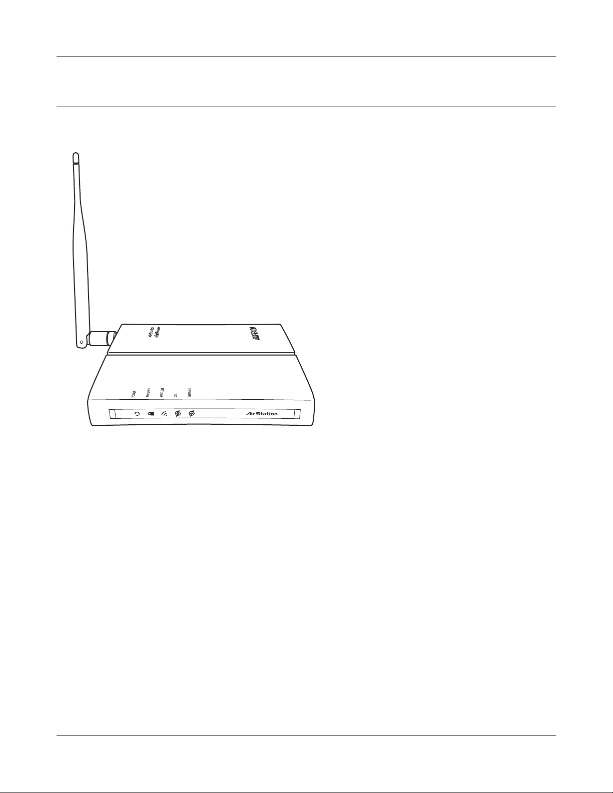
Hardware Overview
Front Panel LEDs / Back Panel
1
2
3
4
5
6
7
8
1
Power LED
On (Green) : The AC adapter is connected.
O (Green) : The AC adapter is not connected.
Shows AirStation status.
2 blinks (Red) *1 : Flash ROM error.
3 blinks (Red) *1 : Wired Ethernet LAN error.
4 blinks (Red) *1 : Wireless LAN error.
5 blinks (Red) *1 : Network error.
9 blinks (Red) *1 : System error.
Continuously
blinking (Red) *2 :
Updating rmware, saving settings, or initializing settings.
9
WBMR-HP-GNV2 User Manual 7
Page 9

Chapter 1 Product Overview
*1 Turn o AirStation rst, wait for a few seconds, then turn it back on.
*2 If the Power LED keeps blinking, do not turn o the AirStation nor unplug its power
cable.
2
Security LED (Amber)
Indicates security status.
O : AOSS or Encryption is not set.
On : AOSS/WPS activated; accessed to exchange security keys.
Encryption has been set.
2 blinks : The unit is waiting for an AOSS or WPS security key.
Blinking : AOSS/WPS error; failed to exchange security keys.
Note : The Security LED is lit if an encryption key has been set.
3
Wireless LED (Green)
Indicates wireless LAN status.
On : Wireless LAN is transmitting.
O : Wireless LAN is not active.
4
DSL LED (Green)
Indicates DSL status.
On : The DSL port is connected.
5
Internet LED
Indicates Internet status.
On (Green) : Connected to Internet
Blinking (Green) : Communicating over Internet
On (Red) : Not connected to Internet
O : Operating in bridge mode
6
DC Connector
Connect the included AC adapter here.
7
LAN LED (Green)
On : An Ethernet device is connected.
Blinking : An Ethernet device is communicating.
8
LAN Port
Connect your computer, hub, or other Ethernet devices to these ports. This switching hub
supports 10 Mbps, 100 Mbps connections.
9
DSL Port
Connect your ADSL line to this port.
WBMR-HP-GNV2 User Manual 8
Page 10
Chapter 1 Product Overview
Top
10
11
10
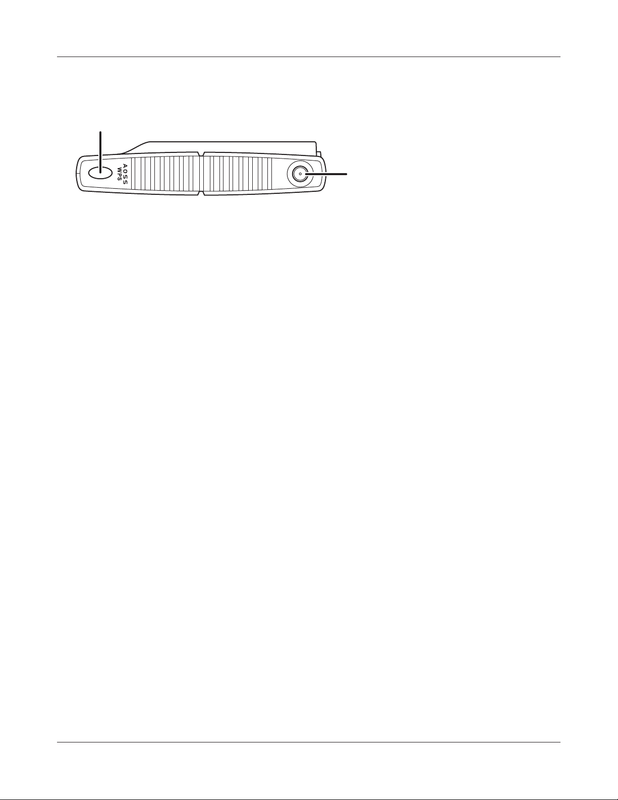
AOSS Button To initiate AOSS, hold down this button until the Security LED ashes
(about 1 second). Then, push or click the AOSS button on your wireless
client device to complete the connection. Both devices must be powered
on for this to work.
11
Antenna connector Screw on the antenna here.
WBMR-HP-GNV2 User Manual 9
Page 11

Chapter 1 Product Overview
Bottom
12
12
Reset Button To reset all settings, hold down this button until the Power LED comes on
(about 3 seconds). Power must be on.
Right Side
13
13
Factory Default Settings This sticker shows the AirStation’s SSID, default encryption
key, and WPS PIN code. By default, encryption is disabled for
AirStations sold in Asia Pacic.
WBMR-HP-GNV2 User Manual 10
Page 12
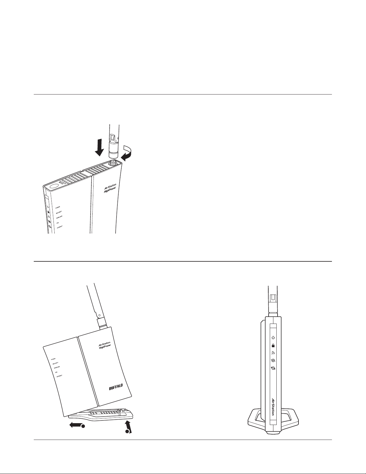
Chapter 2 - Placing Your AirStation
Antenna Placement
The antenna is included in the package. Screw the antenna clockwise to install.
Vertical Placement
To place unit vertically, attach the stand as shown below.
1
2
WBMR-HP-GNV2 User Manual 11
Page 13
Chapter 2 Placing Your AirStation
Horizontal Placement
For horizontal placement, the stand is not used.
WBMR-HP-GNV2 User Manual 12
Page 14

Chapter 2 Placing Your AirStation
Wall-Mounting
1
2
To wall-mount the AirStation, attach
the stand to the wall with the two
screws (included).
8.5 cm
(~3.3 inches)
Snap the center of the AirStation to the stand as shown.
WBMR-HP-GNV2 User Manual 13
Page 15

Chapter 3 - Installation
Automatic Setup
The AirNavigator CD can step you through installing your AirStation. To step through the setup
program, insert the CD into your Windows 7/Vista/XP PC and follow the instructions on the screen.
If your computer uses a dierent operating system, use manual setup instead.
Note: · To use a wireless client in Windows 7 or Vista, perform setup using the AirNavigator CD to automatically
generate a profile for wirelessly connecting to the AirStation. After setup is complete, once the LAN
cable is removed, you can connect from your wireless client to the AirStation.
· Before performing setup, make the settings to enable the wireless client of the computer.
Manual Setup
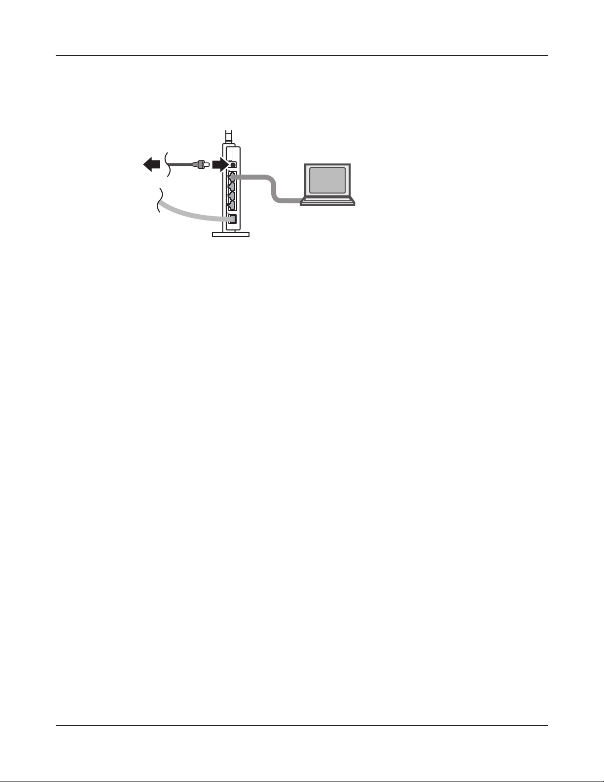
To congure your AirStation manually, follow the procedure below.
1
2
Power o your computers and networking equipment.
Connect your computer to one of the LAN ports on the rear of the AirStation with the
supplied Ethernet network cable.
WBMR-HP-GNV2 User Manual 14
Page 16

Chapter 3 Installation
3
Connection for the AirStation to the ADSL line varies by country and region. Typically it
involves a microlter or a microlter with built-in splitter to allow simultaneous use of ADSL
service and telephone service on the same telephone line. Please read the following steps
carefully and select the appropriate method.
· If your telephone service and ADSL service are on the same telephone line, ADSL microfilters are needed
for each telephone and device, such as answering machine, fax machine, and caller ID display. Additional
splitters may be used to separate telephone lines for telephone and Router.
Note: Do not connect the ADSL microfilter between the wall jack and the Router—this will prevent ADSL
service from reaching the modem.
· If your telephone service and ADSL service are on the same telephone line and you are using an ADSL
microfilter with built-in splitter, connect the splitter to the telephone wall jack providing ADSL service. Then,
connect the telephone cord from the ADSL microfilter RJ11 port generally labelled ‘DSL’ to the gray RJ11
port labelled ‘DSL line’ on the back of your Router. Connect the telephony device to the other port on the
ADSL splitter commonly labelled ‘Phone’.
Note: An RJ11 telephone cord is supplied. When inserting an RJ11 plug, be sure the tab on the plug clicks
into position correctly.
· If you have a dedicated ADSL service telephone line with an RJ11 wall jack, simply connect a telephone cord
from the wall jack to the DSL port on the back of the AirStation.
4
· If you have an RJ45 wall jack for your ADSL service, connect an RJ45-to-RJ11 converter to the wall jack. Then
connect one end of the telephone cord to the converter and the other end to the DSL port on the back of
the AirStation.
Connect your computer to one of the AirStation’s LAN ports with the LAN cable.
AirStation
1) connect
2) connect
LAN cable
OFF
computer
WBMR-HP-GNV2 User Manual 15
Page 17
Chapter 3 Installation
5
6
Turn on the AirStation, wait one minute, and then turn on your computer.
1) Connect the power supply
power outlet
AirStation
ON
computer
Once your computer has booted, the AirStation’s LEDs should be lit as described below:
POWER Green light on.
WIRELESS Green light on or blinking.
DSL Green light on or o depending on your network.
INTERNET Green light on.
LAN Green light on or blinking.
For LED locations, refer to chapter 1.
7
Launch a web browser. If the [home] setup screen is displayed, setup is complete.
If a user name and password screen is displayed, enter [root] (in lower case) for the user
name, leave the password blank, and click [OK]. Step through the wizard to complete setup.
You’ve completed initial setup of your AirStation. Refer to Chapter 4 for advanced settings.
WBMR-HP-GNV2 User Manual 16
Page 18

Chapter 3 Installation
Gathering Information
Most DSL providers require PPPoE or PPPoA details to log in to your connection. You must call your
ISP’s Technical Support number to obtain the following information:
Username : This is the Username that is used to log onto your ADSL service provider’s network. It is
commonly in the form − user@isp.com.
Password : This is the Password that is used, in conjunction with the Username above, to log on to
your ADSL service provider’s network.
Connection Protocol : This is the method that your ADSL service provider uses to send and receive
data between the Internet and your computer.
VPI : This is the Virtual Path Identier (VPI). It is used in conjunction with the Virtual Channel
Identier (VCI) below, to identify the data path between your ADSL service provider’s network
and your computer.
VCI : This is the Virtual Channel Identier (VCI). It is used in conjunction with the VPI above to
identify the data path between your ADSL service provider’s network and your computer.
Note : This information should be stored and kept to hand as it will be required to enable you to establish
an internet connection.
The table below is a quick reference guide for conguring your ADSL Internet connection. You may
try the settings for the ISPs shown.
Country Encapsulation VPI / VCI Multi plexing ISPs
France RFC2516 PPPoE 8/35 LLC Various
RFC2516 PPPoE 8/67 LLC
RFC2364 PPPoA 8/35 VC
Germany RFC2516 PPPoE 1/32 LLC T-Online, Various
WBMR-HP-GNV2 User Manual 17
Page 19

Chapter 3 Installation
Country Encapsulation VPI / VCI Multi plexing ISPs
Holland RFC1483 Bridged 0/35
0/32
0/34
LLC BBNed, XS4all Versatel, DHCP
Baby XL, Tiscali. (start/Surf/
Family/Live)
RFC2364 PPPoA 8/48 VC KPN, Hetnet, HCCNet, Tiscali (lite/
Basis/Plus), Wanadoo
RFC2364 PPPoA 0/32 VC Versatel PPP, Zonnet
RFC2516 PPPoE 8/35 LLC Various
Belgium RFC2364 PPPoA 8/35 LLC Belgacom, Tiscali, Scarlet
Ireland RFC2516 PPPoE 8/35 LLC Eircom, BT, Digiweb,
Irish Broadband
Italy RFC2516 PPPoE 8/35 VC TIN
Spain RFC2516 PPPoE 8/32 LLC Telefonica
Sweden RFC1483 Bridged 3/35 LLC Telia
UK RFC2364 PPPoA 0/38 VC BT, Freeserve, Tiscali, AOL
WBMR-HP-GNV2 User Manual 18
Page 20

Chapter 4 - Conguration
The web-based conguration tool lets you change advanced settings for the AirStation. Don’t
change these settings unless you know what you’re doing.
How to Access the Web-Based Conguration Utility
To congure the AirStation’s advanced settings manually, log in to the web-based conguration
utility as shown below.
1
2
3
Launch a web browser.
Enter the AirStation’s LAN-side IP address in the
address eld, and press the [Enter] key.
Note: The AirStation’s default LAN-side IP address is 192.168.11.1.
If you changed the IP address of the AirStation, then use the new IP address.
When this screen appears, enter [root]
(in lower case) for the user name and the
password that you set during initial setup.
Click [OK].
Note: By default, the password is blank (not set).
If you forget your password, hold down the
Reset button (page 10) to initialize all settings.
The password will then be blank. Note that
all other settings will also revert to their
default values.
WBMR-HP-GNV2 User Manual 19
Page 21

Chapter 4 Conguration
4
This is the conguration utility,
where most AirStation settings
can be congured.
Help is always displayed on
the right side of each screen.
Refer to the Help screens for
more information on using the
conguration utility.
WBMR-HP-GNV2 User Manual 20
Page 22

Chapter 4 Conguration
Conguration Utility Menus
The menu structure for the AirStation is as follows. Please refer to the pages listed at right for
explanations of each item.
Main screen Descriptions Page
Internet/LAN
Internet Congure Internet settings. Page 25
DDNS DNS settings. Page 29
Route Congure the AirStation’s IP communication route. Page 31
Wireless Cong
WPS WPS settings and status. Page 32
AOSS AOSS (AirStation One-touch Secure System) settings and status. Page 33
Basic Congure basic wireless settings. Page 35
Advanced Congure advanced wireless settings. Page 39
WMM Set priorities for Wireless Multimedia Extensions (Wi-Fi Multimedia). Page 40
MAC Filter Limit access to specic devices. Page 42
Security
Firewall Protect your computer from outside intruders. Page 43
IP Filter IP lters for packets passing through the LAN side and the Internet side. Page 44
VPN
Passthrough
LAN Cong
Port Forwarding Congure port translation and exceptions for games and other
DMZ Congure a destination to transfer communication packets without a
UPnP Congure UPnP (Universal Plug and Play). Page 48
QoS Congure priority for packets that require a guaranteed data ow. Page 49
Admin Cong
Name Congure the AirStation’s name. Page 50
Password Congure the AirStation’s login password for access to the conguration
Congure IPv6 passthrough, PPPoE passthrough, and PPTP passthrough. Page 45
Page 46
programs.
Page 48
LAN side destination.
Page 51
utility.
Time/Date Congure the AirStation’s internal clock. Page 52
NTP Congure the AirStation to synchronize with an NTP server to
automatically set the AirStation’s internal clock.
ECO Congure the AirStation’s ECO Mode. Page 54
WBMR-HP-GNV2 User Manual 21
Page 53
Page 23
Chapter 4 Conguration
Access Congure access restrictions to the AirStation’s conguration screens. Page 56
Log Congure a syslog server to manage the AirStation’s logs. Page 57
Save/Restore Save or restore the AirStation’s conguration from a conguration le. Page 58
Initialize/Restart Initialize the AirStation or reboot it. Page 59
Update Update the AirStation’s rmware. Page 60
Diagnostic
System Info View current system information for the AirStation. Page 61
Logs Check the AirStation’s logs. Page 63
Packet Info View all packets transferred by the AirStation. Page 64
Client Monitor View all devices currently connected to the AirStation. Page 65
Ping Test the AirStation’s connection to other devices on the network. Page 66
DSL Connection View DSL Connection for the AirStation. Page 67
Logout
Click this to log out of the AirStation’s conguration screens.
WBMR-HP-GNV2 User Manual 22
Page 24

Chapter 4 Conguration
Setup
Setup is the home page of the conguration utility. You can verify settings and the status of the
AirStation here.
Parameter Meaning
Internet/LAN (LAN Cong) Displays the conguration screen for the Internet port and LAN
ports.
Wireless Cong Click this button to display the conguration screen for wireless
settings.
Security Click this button to display the conguration screen for security.
LAN Cong Click this button to display the conguration screen to open ports
for games and applications.
Admin Cong Click this button to display the conguration screen for
administration settings.
Diagnostic Click this button to display the status of the AirStation.
Easy Setup Enables you to easily congure the AirStation’s network settings
automatically.
Internet Information Displays WAN-side system information for the AirStation.
WBMR-HP-GNV2 User Manual 23
Page 25

Chapter 4 Conguration
Parameter Meaning
WIRELESS Displays the current wireless settings.
AOSS Setup Click this button to display the AOSS conguration screen.
WPS Setup Click this button to display the WPS conguration screen.
Language Enables you to select the language you use.
Logout Log out from the conguration screen of the AirStation. If the
AirStation does not communicate for 5 minutes, it will log out
automatically.
WBMR-HP-GNV2 User Manual 24
Page 26

Chapter 4 Conguration
Internet/LAN
Internet
The Internet settings are made here. For details on the settings, refer to the documentation
provided by your ADSL provider.
WBMR-HP-GNV2 User Manual 25
Page 27

Chapter 4 Conguration
Parameter Meaning
Internet Setup
Encapsulation Set the ADSL communication method.
Modulation Set the modulation system used in ADSL communication.
Multiplexing Set the encapsulation system for VC multiplexing.
Select from LLC (Logical Link Control Encapsulation) which can
handle multiple protocols or VC (Virtual Circuit) for a single
protocol.
QoS Type Set the QoS (Quality of Service).
Select from the three service categories (UBR, CBR, VBR) where the
QoS is guaranteed in the band.
PCR Rate Set the PCR (Peak Cell Rate) when CBR or VBR is selected for QoS
Type. The network upper limit transfer speed is set in the range
from 1 to 65534 cps.
SCR Rate Set the SCR (Sustainable Cell Rate) when CBR or VBR is selected
for QoS Type. The network sustainable transfer speed is set in the
range from 1 to 65534 cps.
Auto Detect Set to VPI (Virtual Path Identication) or VCI (Virtual Channel
Identication) of the virtual circuit when Disable is selected for
Auto Detect.
Virtual Circuit Set automatic detection of the virtual circuit.
Obtain an IP Address
Automatically(DHCP)/Use following
IP Address
This option is displayed when RFC1483 Bridged is selected in the
Encapsulation eld.
Select whether the IP address, subnet mask, gateway, and DNS are
obtained automatically or manually.
Internet IP Address Set the “public” (or “global”) IP address that identies your
broadband gateway on the Internet.
Subnet Mask Set the Internet subnet mask.
Gateway Set the Gateway address specied by the provider.
Primary DNS / Second DNS Set the DNS server address specied by the provider.
Service Name Set the service name specied by the provider in 64 or less single-
byte alphanumeric characters.
WBMR-HP-GNV2 User Manual 26
Page 28

Chapter 4 Conguration
Parameter Meaning
User Name Set the user name (PPP login name) specied by the provider in 64
or less single-byte alphanumeric characters and symbols.
If the name specied by the provider contains an @ mark, the
characters after the @ mark cannot be omitted when entering the
User Name.
Password Set the password specied by the provider in 64 or less single-byte
alphanumeric characters and symbols.
Connect on Demand/Keep Alive Select the Connect on Demand or Keep Alive.
When Connect on Demand is selected, the AirStation is
automatically connected to the server only when communication is
performed. The connection is disconnected if the communication is
not performed for a preset time (disconnect time).
Set the disconnect time in the range from 1 to 9999 minutes.
When Keep Alive is selected, the AirStation issues an LCP echo
request to the server periodically at preset time intervals, and
the response received from the server is used to conrm that
communication is enabled.
If no response from the server is received, the AirStation assumes
that the line is disconnected, and it disconnects the connection.
Set the Keep Alive time interval in the range from 20 to 180
seconds.
Host Name Set the host name that is sent to the server when acquiring the IP
address from the Internet.
Domain Name Set the domain name.
MTU Set the MTU (Maximum Transmission Unit) that is used in
communication.
Select from Auto or Manual. When set to Manual, the available
range is set from 576 to 1500 bytes.
Network Setup
Local IP Address / Subnet Mask By default, the LAN side IP address is 192.168.11.1 with subnet
mask 255.255.255.0. You may change it here.
Local DHCP Server The factory setting of this control, Enable, sets the gateway to act
as a DHCP server for local machines. When this setting is used, you
can set a range of IP addresses to be assigned by DHCP. Addresses
outside this range can be assigned manually to machines set to use
xed IP settings.
WBMR-HP-GNV2 User Manual 27
Page 29

Chapter 4 Conguration
Parameter Meaning
DHCP Relay Server When Local DHCP Server is set to DHCP Relay, you must enter
the IP address of the remote DHCP server here. (Note that “DHCP
relay server” is a widely used but incorrect term for a remote DHCP
server.)
Starting IP Address This is the lowest address in the range that the gateway will assign
by DHCP.
Maximum Number of DHCP Users This is the number of addresses that can be assigned by DHCP.
Client Lease Time This is the number of minutes any DHCP client is given exclusive
use of a (non-reserved) DHCP-assigned IP address. This can be from
1 to 9999.
Static DNS 1 / Static DNS 2 / Static DNS 3 Enter the IP address(es) of one to three name servers.
WINS Enter the IP address of a Windows Internet Name Service server, if
such a server is available to you.
WBMR-HP-GNV2 User Manual 28
Page 30

Chapter 4 Conguration
DDNS (Router Mode only)
Congure Dynamic DNS settings. Many settings are only available when the appropriate Dynamic
DNS service is enabled.
Parameter Meaning
DDNS Service Select a provider (DynDNS or TZO) for Dynamic DNS.
User Name Enter the Dynamic DNS user name. You may enter up to 64
alphanumerical characters and symbols.
Password Enter the Dynamic DNS password. You may enter up to 64
alphanumerical characters and symbols.
Host Name Enter the Dynamic DNS host name. You may enter up to 255
alphanumerical characters, hyphens, and periods.
Email Address Enter the email address which is registered to the Dynamic DNS
service. You may enter up to 64 alphanumerical characters and
symbols.
TZO Key Enter the TZO Key which is registered to the Dynamic DNS service.
You may enter up to 64 alphanumerical characters and symbols.
Domain Name Enter the domain name which is registered to the Dynamic DNS
service. You may enter up to 255 alphanumerical characters,
hyphens, and periods.
WBMR-HP-GNV2 User Manual 29
Page 31

Chapter 4 Conguration
Parameter Meaning
IP Address Update Period Species the period to notify the dynamic DNS service provider of
the current IP address. For DynDNS, set it between 0 and 35 days.
For TZO, set it between 0 and 99 days. If 0 (zero) days is set, no
periodic update is performed.
Internet Side IP Address The WAN-side IP address of the AirStation’s Internet port. This
address is sent to the dynamic DNS service provider.
Domain Name The domain name assigned by the dynamic DNS Service provider.
The AirStation can be accessed from the Internet using this domain
name.
Status Display the status of dynamic DNS service.
WBMR-HP-GNV2 User Manual 30
Page 32

Chapter 4 Conguration
Route
Congure the AirStation’s IP communication route.
Parameter Meaning
Destination Address Adds a destination IP address and subnet mask to a routing table.
Gateway Adds a gateway address to a routing table.
Metric The metric is the maximum number of router hops a packet may
take on the way to its destination address. Values between 1 and 15
may be entered. The default value is 15.
Routing Information Manual entries will appear here after being added.
WBMR-HP-GNV2 User Manual 31
Page 33

Chapter 4 Conguration
Wireless Cong
WPS
WPS Status and Settings.
Parameter Meaning
WPS Enable to use WPS automatic conguration.
External Registrar Enable to accept the external congure requests from other WPS
devices.
Note: External congure requests will not be accepted if AOSS is in use.
AirStation PIN Displays the PIN code of the AirStation. Clicking [Generate PIN]
will generate a new PIN code. This code can be entered into other
wireless devices that support WPS.
Enrollee PIN Enter the PIN code for the other wireless device and click [OK].
WPS status Displays [congured] if all available wireless bands are
congured. Displays [uncongured] if at least one wireless band is
uncongured.
WBMR-HP-GNV2 User Manual 32
Page 34

Chapter 4 Conguration
AOSS
AOSS Status and Settings.
WBMR-HP-GNV2 User Manual 33
Page 35

Chapter 4 Conguration
Parameter Meaning
Initiates AOSS automatic wireless conguration. Click this, then
press or click the AOSS button on your AOSS-compatible wireless
client. Repeat for additional AOSS clients.
Click this button to disconnect AOSS connections.
Note: If AOSS connections are disconnected, the SSID and encryption keys
will be restored to their most recent settings before using AOSS.
Encryption Type of Exclusive SSID for
WEP
You may allow a separate SSID specically for WEP connections. If
[disabled] is selected, then clients will not be able to connect with
WEP.
Advanced Encryption Level feature Expands security method from TKIP to WPA/WPA2-PSK-mixed
mode.
Exclusive SSID for WEP Set a separate SSID and network segment specically for WEP
connections. Devices connected with WEP will not be able
to communicate with devices connected using AES/TKIP. All
connected devices will be able to communicate with the internet.
AOSS Button on the AirStation Unit Uncheck to disable the physical AOSS button on the AirStation.
Current Encryption Information
* AOSS Connection only
AOSS Client Information*
* AOSS Connection only
Displays the encryption type, SSID, an encryption key congured
by AOSS.
Displays AOSS clients connected to the AirStation and information
of the devices which are wirelessly communicated.
WBMR-HP-GNV2 User Manual 34
Page 36

Chapter 4 Conguration
Basic
The screen to congure a basic wireless settings.
WBMR-HP-GNV2 User Manual 35
Page 37

Chapter 4 Conguration
Parameter Meaning
Wireless Radio Determines whether to allow wireless communication. If this is
unchecked, then no wireless connections will be allowed.
Wireless Channel Sets a channel (a range of frequencies) used for wireless
connections. With Auto Channel selected, the AirStation will
automatically use the best available channel.
150 Mbps Mode 150 Mbps mode is a method to increase wireless transmission
throughput to 40 MHz per channel. To use 150 Mbps mode, set the
Bandwidth to 40 MHz and choose an Extension Channel.
Note: If using Auto Channel for the wireless channel, then the Extension
Channel is set automatically.
Broadcast SSID If [Allow] is checked, then the AirStation will respond to SSID
searches from wireless devices by broadcasting its SSID. If [Allow] is
unchecked, then the AirStation ignores SSID searches from wireless
devices.
[Use Multi Security function]
[Do not use Multi Security function]
Clicking [Use Multi Security function] will enable Multi Security,
allowing the use of multiple SSIDs, each with dierent wireless
security settings. Clicking [Do not use Multi Security function] will
disable the Multi Security function. The AirStation will then allow
one SSID and one type of wireless security.
SSID1 Always enabled and supports all wireless encryption types.
Encryption can be disabled.
SSID2 Always enabled and supports all wireless encryption types.
Encryption can be disabled.
SSID3 SSID3 can use WPA-PSK-AES encryption.
SSID4 SSID4 can use WEP encryption.
Separate feature When [use] is enabled, wireless devices connected to the AirStation
can communicate only with the Internet side, not with each other.
SSID Set SSID using 1-32 alphanumeric characters.
Wireless authentication Species an authentication method used when connecting to a
wireless device.
WBMR-HP-GNV2 User Manual 36
Page 38

Chapter 4 Conguration
Parameter Meaning
Wireless encryption You may use any of the following types of encryption:
No encryption
Data is transmitted without encryption. Avoid this option since
any communication may be intercepted.
[No encryption] can be selected only when [No authentication] is
selected for Wireless authentication.
WEP
WEP is a common encryption method supported by most
devices. Use an encryption key to communicate with a wireless
device.
WEP can only be selected when [No authentication] is selected
for Wireless authentication.
TKIP
TKIP is an encryption method which is more secure than WEP, but
slower. Use an pre-shared-key to communicate with a wireless
device.
TKIP can be selected only when WPA-PSK or WPA2-PSK is selected
for Wireless authentication.
AES
AES is more secure than TKIP, and faster. Use a pre-shared-key to
communicate with a wireless device.
AES can be selected only when WPA-PSK or WPA2-PSK is selected
for Wireless authentication.
TKIP/AES mixed mode
TKIP/AES mixed mode allows both TKIP and AES authentication
and communication.
TKIP/AES mixed mode can be selected only when WPA/WPA2
mixed mode - PSK is selected for Wireless authentication.
WBMR-HP-GNV2 User Manual 37
Page 39

Chapter 4 Conguration
Parameter Meaning
WPA-PSK (Pre-Shared Key) A pre-shared key or passphrase is the [password] for your wireless
connections. There are two dierent formats for a pre-shared key.
Use 8 to 63 alphanumeric characters (case-sensitive) for a [character]
(ASCII) passphrase, or use 64 digits using 0 to 9 and a to f (not casesensitive) for a [hexadecimal] passphrase..
Rekey interval Set the update interval for the encryption key between 0 and 1440
(minutes).
Set up WEP encryption key A WEP encryption key (passphrase) may have any of four dierent
formats. A [character] (ASCII) passphrase may use either 5 or 13
alphanumeric characters (case-sensitive). A [hexadecimal] passphrase
may use either 10 or 26 digits using 0 to 9 and a to f (not case-sensitive).
WBMR-HP-GNV2 User Manual 38
Page 40

Chapter 4 Conguration
Advanced
Congure advanced wireless settings.
Parameter Meaning
BSS Basic Rate Set Set the communication speeds of administrative and
communication control frames of the AirStation and wireless
devices.
Multicast Rate Set the communication speed of multi-cast packets.
Reverse Direction Grant For faster wireless communication, you may enable receiving
packets while sending packets.
DTIM Period Set the beacon responding interval (1 -255) for which the AirStation
responds to a wireless device. This setting is eective only when
power management is enabled for the wireless device.
Privacy Separator If enabled, the Privacy Separator blocks communication between
wireless devices connected to the AirStation. Wireless devices will
be able to connect to the Internet but not with each other. Devices
that are connected to the AirStation with wired connections will
still be able to connect to wireless devices normally.
Output Power
You may reduce the wireless radio power output. The power of a
radio wave and the distance that that radio wave reaches are almost
proportional, so if the output power is reduced, the distance that the
signal reaches also becomes smaller.
WBMR-HP-GNV2 User Manual 39
Page 41

Chapter 4 Conguration
WMM
Set priorities for specic communications.
WBMR-HP-GNV2 User Manual 40
Page 42

Chapter 4 Conguration
Parameter Meaning
WMM-EDCA Parameters You don't usually need to change these settings. Using the default
settings is recommended.
Priority
The following priorities may be applied to individual
transmission packets: (Highest) 8, (High) 4, (Normal) 2, and
(Low) 1. From the queue, these packets are processed in order of
priority.
CWmin, CWmax
The maximum and minimum value of the contention window.
The contention window is used in the frame collision avoidance
structure performed in IEEE802.11, and generally, the smaller the
value in the window, the higher the probability that the queue
obtains the right to send.
AIFSN
The interval to send frames. The unit of the AIFSN is a slot, just as
the window dened by CWmin and CWmax is. The smaller the
interval of sending frames, the faster the algorithm can restart.
As a result, the priority of the queue is higher.
TXOP Limit
The period of time that the queue can use after obtaining the
right to send. The unit is 32 ms. The longer this time, the more
frames can be sent per right to send. However, the queue may
interfere with other packet transmissions. If TXOP Limit is set to 0
(zero), only one frame can be sent per right to send.
WBMR-HP-GNV2 User Manual 41
Page 43

Chapter 4 Conguration
MAC Filter
Restrict access to specic wireless devices.
Parameter Meaning
Enforce MAC Filtering Enable to restrict wireless connections to devices with registered
MAC addresses.
Registration List Displays the MAC addresses of registered devices which are
permitted to connect wirelessly.
[Edit Registration List] Click to add a wireless device to the list of permitted devices.
MAC Addresses to be Registered Enter a MAC address of a wireless device to permit to connect to
the AirStation. Click [Register] to add that MAC address to the list.
List of all clients that are associated
with this AirStation
Display the list of all MAC addresses of wireless devices connected
to the AirStation.
WBMR-HP-GNV2 User Manual 42
Page 44

Chapter 4 Conguration
Security (Router Mode only)
Firewall (Router Mode only)
Congure the AirStation’s rewall.
Parameter Meaning
Log Output Enable to output a log of rewall activity.
Basic Rules Enable to use any of the quick lters. Precongured quick lters
include:
Prohibit NBT and Microsoft-DS Routing
When this is enabled, you cannot use the Microsoft network
feature from the Internet side to the LAN side and from the LAN
side to the Internet.
Reject IDENT Requests
Enabling this option will answer IDENT requests from the Internet
side with corresponding rejection packets. Enable this option if
you experienced slower transfer speed for network application
such as sending mail, using ftp or displaying on browser. If
you have congured transfer of IDENT requests to the LAN
side computer in the address translation settings (DMZ or TCP
port:113), then that setting has higher priority, and overrides this
setting.
Block Ping from Internet
If this is enabled, the AirStation will not respond to pings from the
Internet side.
WBMR-HP-GNV2 User Manual 43
Page 45

Chapter 4 Conguration
IP Filter (Router Mode only)
Edit IP lters.
Parameter Meaning
Log Output If enabled, IP lter activity is saved to a log.
Operation Specify how to process target packets.
Direction Specify the transmission direction of target packets.
IP Address Specify the sender's IP address and receiver's IP address of the
target packets.
Protocol Select a protocol for target transmission packet.
IP Filter Information Display the list of IP lters which have been registered.
WBMR-HP-GNV2 User Manual 44
Page 46

Chapter 4 Conguration
VPN Pass Through (Router Mode only)
Congure IPv6 pass through, PPPoE pass through, and PPTP pass through.
Parameter Meaning
PPPoE Pass Through Enable to use PPPoE bridge. Using PPPoE bridge lets you
automatically obtain an IP address from your provider using the
PPPoE protocol from your computer connected to the LAN side
because all PPPoE packets can pass through between the Internet
and LAN.
PPPTP Pass Through Enable to use the PPTP Pass Through for address translation.
WBMR-HP-GNV2 User Manual 45
Page 47

Chapter 4 Conguration
LAN Cong
Port Forwarding (Router Mode only)
Congure port translation.
Parameter Meaning
Group Specify a group name for a new rule to belong to. Select [New
Group] and enter the new group name in the Group Name
eld to create a new group. A group name can include up to 16
alphanumeric letters.
Protocol Select the Internet side protocol (before translation) for the port
translation table entry.
WBMR-HP-GNV2 User Manual 46
Page 48

Chapter 4 Conguration
Parameter Meaning
LAN Side IP Address Enter the LAN side IP address (after translation) for the port
translation table entry.
LAN Side Port Select the LAN side (after translation) port number (1 - 65535) for
the port translation table entry.
Port Forwarding Registration
Information
Shows current entries in the port translation table.
WBMR-HP-GNV2 User Manual 47
Page 49

Chapter 4 Conguration
DMZ (Router Mode only)
Congure a destination to transfer communication packets without a LAN side destination to.
Parameter Meaning
IP Address of DMZ Enter the IP address of the destination to which packets which are
not routed by a port translation table are forwarded.
Note: RIP protocol packets (UDP port number 520) will not be
forwarded.
UPnP (Router Mode only)
Congure UPnP (Universal Plug and Play).
Parameter Meaning
UPnP Enable or disable Universal Plug and Play (UPnP) functionality.
WBMR-HP-GNV2 User Manual 48
Page 50

Chapter 4 Conguration
QoS (Router Mode only)
Congure the priority of packets sent to the Internet.
Parameter Meaning
QoS for transmission to the Internet Determine whether or not to prioritize packets sent to the Internet.
Check this box to enable QoS.
Upload bandwidth Specify the upstream bandwidth in kbps from the AirStation to the
internet side. Set the actual value for the upstream bandwidth.
Enable Enable or disable this entry.
application name Enter an application name. Names may use up to 32 alpha
numerical characters, double or single tick marks ("'), quotation
marks (“), and semicolons (;).
protocol Select either TCP or UDP.
WBMR-HP-GNV2 User Manual 49
Page 51

Chapter 4 Conguration
Parameter Meaning
destination port Specify a destination port with the value of 1 - 65535. If this eld is
empty, a random port is selected.
priority Select high, medium or low. If packets do not qualify for classication
as a type on the list, then their priority is treated as a level between
medium and low.
Admin Cong
Name
Congure basic AirStation’s settings.
Parameter Meaning
AirStation Name Enter a name for the AirStation. Names may include up to 64
alphanumeric characters and hyphens (-).
WBMR-HP-GNV2 User Manual 50
Page 52

Chapter 4 Conguration
Password
Congure the password to log in to the AirStation’s conguration screen.
Parameter Meaning
Administrator Name The Administrator name is used to log in to the AirStation’s
conguration utility. This name is xed as [root].
Administrator Password The password is required to log in. It may contain up to 8
alphanumeric characters and underscores (_).
WBMR-HP-GNV2 User Manual 51
Page 53

Chapter 4 Conguration
Time/Date
Congure the AirStation’s internal clock.
Parameter Meaning
Local Date You may manually set the date of the AirStation’s internal clock.
Local Time You may manually set the time of the AirStation’s internal clock.
Time Zone Specify the time zone (oset of Greenwich Mean Time) of the
AirStation’s internal clock.
WBMR-HP-GNV2 User Manual 52
Page 54

Chapter 4 Conguration
NTP
Congure an NTP server to automatically synchronise the AirStation’s internal clock.
Parameter Meaning
NTP Functionality Enable to use an NTP server. The default is disabled.
NTP Server Enter the name of the NTP server as a host name, host name with
domain name, or IP address. Up to 255 alphanumeric characters,
hyphens (-), and underscores (_) may be used. The default is [time.
nist.gov].
Update Interval How often will the AirStation check the NTP server for the correct
time? Intervals of 1 - 24 hours may be set. The default is 24 hours.
WBMR-HP-GNV2 User Manual 53
Page 55

Chapter 4 Conguration
ECO
Congure Eco mode from this screen.
WBMR-HP-GNV2 User Manual 54
Page 56

Chapter 4 Conguration
Parameter Meaning
Schedule feature Enable to schedule Eco mode.
Note: If Schedule is enabled, AOSS will only function while the
AirStation is in Normal Operating Mode.
Weekly schedule Graphically displays the congured schedule.
Register schedule Congure operational mode for time periods in the weekly
schedule. If User Dened mode is chosen, congure it below.
User Dene Mode Individual power saving elements may be congured individually
for User Dened mode.
WBMR-HP-GNV2 User Manual 55
Page 57

Chapter 4 Conguration
Access
Restrict access to the AirStation’s settings screens.
Parameter Meaning
Log Output Enabling outputs a log of changes to access settings.
Prohibit conguration from wireless
LAN
Prohibit conguration from wired
LAN
Permit conguration from wired
Internet
Permitted IP address Displayed only if Internet side conguration is enabled. Enter the
Permitted Port Displayed only if Internet side conguration is enabled. Set a port
If enabled, prevents access to settings screens from wirelessly
connected devices (only wired devices may congure).
If enabled, prevents access to settings screens from wired devices
(only wirelessly connected devices may congure).
If enabled, allows access to settings screens from network devices
on the WAN (Internet) side.
IP address of a device that is permitted to congure the AirStation
remotely from the WAN (Internet) side.
number (1 - 65535) to congure the AirStation from the WAN
(Internet) side.
WBMR-HP-GNV2 User Manual 56
Page 58

Chapter 4 Conguration
Log
Transfer the AirStation’s logs to a syslog server.
Parameter Meaning
Log Transfer Enable to send logs to a syslog server.
Syslog Server Identify the syslog server by host name, host name with domain
name, or IP address. You may enter up to 255 alphanumeric
characters, hyphens (-), and underscores (_).
Transfer Logs Choose which logs will be transferred to the syslog server.
WBMR-HP-GNV2 User Manual 57
Page 59

Chapter 4 Conguration
Save/Restore
Save AirStation settings as a le, and restore from them later.
Parameter Meaning
Save current settings Clicking [Save] will save the current conguration of the AirStation
to a le. If the [Encrypt the conguration le with a password]
option is checked, then the conguration le will be password
protected with the current Administrator Password.
Restore Conguration from Backup
File
Restore the conguration of the AirStation from a saved
conguration le by clicking the [Browse...] button, navigating to
the conguration le, and then clicking Restore. If the conguration
le was password protected, then put a check next to [To restore
from the le you need the password], enter the password, and click
[Open].
WBMR-HP-GNV2 User Manual 58
Page 60

Chapter 4 Conguration
Initialize/Restart
Initialize or restart the AirStation.
Parameter Meaning
Restart Click [Restart Now] to restart the AirStation.
Initialize Click [Initialize Now] to initialize and restart the AirStation.
WBMR-HP-GNV2 User Manual 59
Page 61

Chapter 4 Conguration
Update
Update the AirStation’s rmware.
Parameter Meaning
Firmware Version Displays the current rmware version of the AirStation.
Update Method Specify Local File
Updates from a rmware le stored on your computer.
Automatic Update (On Line Version Up)
Automatically updates to the latest rmware available.
Firmware File Name Click [Browse...] to navigate to the rmware le on your computer
if [Specify Local File] was selected. You don’t need to specify the
rmware location if you’re using [Automatic Update]. Click [Update
Firmware] to update the rmware.
WBMR-HP-GNV2 User Manual 60
Page 62

Chapter 4 Conguration
Diagnostic
System Info
View system information for the AirStation.
WBMR-HP-GNV2 User Manual 61
Page 63

Chapter 4 Conguration
Parameter Meaning
Model Displays the product name of the AirStation and the rmware
version.
AirStation Name Displays the AirStation Name.
Operational Mode Displays the current operational mode of the AirStation.
Internet Displays the information about the Internet port.
LAN Displays the information about the LAN port.
Wireless Displays the wireless status.
ECO Mode This indicates the operating status of ECO Mode.
WBMR-HP-GNV2 User Manual 62
Page 64

Chapter 4 Conguration
Logs
The AirStation’s logs are recorded here.
Parameter Meaning
Display log info Choose the types of logs to display.
Logs Displays the log information recorded in the AirStation.
WBMR-HP-GNV2 User Manual 63
Page 65

Chapter 4 Conguration
Packet Info
View packet transfer information.
Parameter Meaning
Sent Displays the number of packets sent to the Internet side of
Ethernet, the LAN side of the Ethernet, and the LAN side of the
wireless connection.
Received Displays the number of packets received from the Internet side
of Ethernet, the LAN side of the Ethernet, and the LAN side of the
wireless connection.
WBMR-HP-GNV2 User Manual 64
Page 66

Chapter 4 Conguration
Client Monitor
This screen shows devices that are connected to the AirStation.
Parameter Meaning
Client Monitor Displays information ( MAC address, lease IP address, host name,
communication method, wireless authentication and 802.11n) for
devices that are connected to the AirStation.
WBMR-HP-GNV2 User Manual 65
Page 67

Chapter 4 Conguration
Ping
A Ping test checks whether the AirStation can communicate with a specic network device.
Parameter Meaning
Destination Address Enter an IP address or a host name of the device for which you
try to verify the connection, and click [Execute]. The result will be
displayed in the [Result] eld.
WBMR-HP-GNV2 User Manual 66
Page 68

Chapter 4 Conguration
DSL Connection
View DSL Connection for the AirStation.
Parameter Meaning
DSL Status If a DSL link has been established, technical information about it is
shown here.
PCV Connection This section reects settings in the Internet Connection Type and
VC settings sections of the Internet/LAN setup panel. See that
panel’s Help page for detailed descriptions.
WBMR-HP-GNV2 User Manual 67
Page 69

Chapter 5 - Connect to a Wireless Network
Automatic Secure Setup (AOSS/WPS)
AOSS and WPS are systems which enable you to automatically congure wireless LAN settings. Just
pressing the buttons will connect wireless devices and complete security settings. Easily connect to
any wireless devices, computers, or game machines which support AOSS or WPS.
AOSS (AirStation One-Touch Secure System) was developed by Bualo Technology. WPS
was created by the Wi-Fi Alliance.
Internet
PUSH
PUSH
AirStation PC or
Game console
(AOSS Devices)
• Before using AOSS or WPS to connect to a Bualo wireless client, install Client Manager software
from the included AirNavigator CD. Consult your wireless client’s documentation for more
information.
• Bualo’s Client Manager software can be used with the wireless LAN devices built into your
computer. However, it is not guaranteed to work with all wireless LAN devices available. Some
wireless clients may require manual setup.
WBMR-HP-GNV2 User Manual 68
Page 70

Chapter 5 Connect to a Wireless Network
Windows 7/Vista (Client Manager V)
If you are using Windows 7/Vista, use the included Client Manager V software to connect wirelessly
with AOSS/WPS.
1
2
3
4
Click the icon in the system tray.
When the screen at left is displayed, click [Create
Pro le].
If the User Account Control screen opens, click [Yes] or [Continue].
Click the [WPS AOSS] button.
Follow any instructions displayed on the screen. When the Security LED on the front of the
AirStation stops ashing and is lit steadily, the connection is complete.
WBMR-HP-GNV2 User Manual 69
Page 71

Chapter 5 Connect to a Wireless Network
Windows XP (Client Manager 3)
If you are using Windows XP, use Client Manager 3 to connect wirelessly with AOSS/WPS.
1
Right click on the icon in the system tray, and select [Pro le].
2
Click the [WPS AOSS] button.
Follow any instructions displayed on the screen. When the Security LED on the front of the
AirStation stops ashing and is lit steadily, the connection is complete.
Other Devices (e.g. Game Console)
If you are using a game machine which supports AOSS or WPS, refer to that device’s manual to
initiate AOSS/WPS. When instructed, hold down the AOSS button on the AirStation for 1 second.
When the Security LED stops blinking and is lit steadily, the connection is complete.
WBMR-HP-GNV2 User Manual 70
Page 72

Chapter 5 Connect to a Wireless Network
Manual Setup
You can also connect to the AirStation without installing Client Manager V or Client Manager 3 by
using the utility built-in to Windows. The procedure varies depending on which version of Windows
you are using.
Note: · If the AirNavigator CD is used to perform setup when making the initial settings of AirStation, the
wireless connection settings for the AirStation are completed during the Setup process. As a result, you
do not need to make the settings below. After setup is complete, once the LAN cable is removed, you
can connect from your wireless client to the AirStation.
· Before performing setup, make the settings to enable the wireless client of the computer.
Windows 7 (WLAN AutoCong)
With Windows 7, use WLAN AutoCong to connect to the AirStation.
1
2
Click on the network icon in the system tray.
Select the target AirStation’s name and click
[Connect]. If you will be connecting to this
device in the future, checking [Connect
automatically] is recommended.
WBMR-HP-GNV2 User Manual 71
Page 73

Chapter 5 Connect to a Wireless Network
3
Enter the encryption key and click [OK].
Windows Vista (WLAN AutoCong)
With Vista, use WLAN AutoCong to connect to the AirStation.
1
2
3
Right click on the wireless network icon in the system tray.
Click [Connect to a network].
When the screen at left is displayed, select the
network to connect to and click [Connect].
WBMR-HP-GNV2 User Manual 72
Page 74

Chapter 5 Connect to a Wireless Network
If the screen below is displayed, click [I want to enter the network key or passphrase instead].
Otherwise, go to step 4.
WBMR-HP-GNV2 User Manual 73
Page 75

Chapter 5 Connect to a Wireless Network
4
Step through the wizard to nish conguration.
select [Home], [Work], or [Public location] depending where you’re using the AirStation.
Enter the encryption key and click [Connect].
If the Set Network Location screen is displayed,
WBMR-HP-GNV2 User Manual 74
Page 76

Chapter 5 Connect to a Wireless Network
Windows XP (Wireless Zero Conguration)
Windows XP includes a built-in utility to connect to your AirStation.
Note: If Client Manager 3 is installed on your computer, Wireless Zero Conguration is disabled. Uninstall Client
Manager 3 to use Wireless Zero Conguration, or just use Client Manager 3 to connect to the AirStation.
1
2
3
4
Right click on the wireless network icon displayed in the system tray.
Click [View Available Wireless Networks].
Select the network to connect to and click
[Connect].
Enter the encryption key (twice) and click
[Connect].
Follow the instructions displayed on the screen to nish conguration.
WBMR-HP-GNV2 User Manual 75
Page 77

Chapter 5 Connect to a Wireless Network
Mac OS X (AirPort)
Use AirPort in the Mac OS X to connect to the AirStation.
1
Refer to the label on the side of the AirStation, and
make a note of the SSID and KEY printed on the
label.
2
3
4
Click the icon in the top
section of the screen, and select
[Turn Airport On].
Click the value that matches the
SSID that was noted in step 1.
Enter the value for the KEY that was
noted in step 1 into the Password
entry box, insert a check mark into
[Remember this network], and click
[OK].
Follow the instructions displayed on the screen to nish conguration.
WBMR-HP-GNV2 User Manual 76
Page 78

Chapter 6 - Trouble Shooting
Cannot connect to the Internet over wired connection.
• Make sure that your AirStation is plugged in!
• Check that the status LEDs of your AirStation are lit as below:
Power Green light is ON
DSL Green light is ON or OFF (depending on your environment)
Internet Green light is ON or ashing
• Make sure that your computer is set to [Obtain an IP address automatically]. (see appendix C)
• Refer to the documentation provided by your provider, and make the correct ADSL settings.
• Restart your AirStation.
Cannot access the web-based conguration utility.
• See chapter 4 for instructions to open the AirStation’s conguration utility.
• Enter the correct user name and password to login to the conguration screen. The factory
defaults are [root] (in lower case) for the user name and a blank password (enter nothing). If you
changed the password, enter the new password that you set.
• Verify that your web browser is not set to use proxies.
• Make sure that your computer is congured to [Obtain an IP Address Automatically]. (see appendix
C)
• Restart your AirStation.
WBMR-HP-GNV2 User Manual 77
Page 79

Chapter 6 Trouble Shooting
Cannot connect to the network wirelessly.
• Congure your wireless client with the same SSID, encryption type, and encryption key as set
on the AirStation.
The factory defaults are:
SSID - BUFFALO-XXXXXX (the last 6 digits of the AirStation’s MAC address)
Encryption Type - WPA/WPA2 mixed mode - PSK (Connect with either WPA-PSK TKIP or
WPA2-PSK AES).
Encryption Key - Printed on the label of the AirStation.
Note: Encryption is disabled by default in Asia Pacic.
• Place your AirStation and wireless devices 2 - 10 feet apart.
• Restart your AirStation.
You forgot AirStation’s SSID, Encryption Key, or Password.
Hold down the Reset button on the base of your AirStation for 3 seconds to initialize its settings. All
settings, including your password, SSID, and encryption key will be initialized to their defaults. The
factory defaults are:
SSID - BUFFALO-XXXXXX (the last 6 digits of the AirStation’s MAC address)
Encryption Type - WPA/WPA2 mixed mode - PSK (Connect with either WPA-PSK TKIP or
WPA2-PSK AES).
Encryption Key - Printed on the label of the AirStation.
(Encryption is disabled by default for Asia Pacic AirStations.)
The link speed is slower than 150 Mbps (Maximum link speed is only 65 Mbps).
By default, the AirStation’s 150 Mbps mode is not enabled. You may enable it with the following
procedure:
1. Open the conguration utility (chapter 4).
2. Click [Wireless SSID & Channel (11n 150 Mbps Mode)] in Easy Setup.
3. Change the value in [150 Mbps Mode] - [Band Width] to 40 MHz and click [Apply].
If you still cannot connect at 150 Mbps, check the settings of your wireless client device.
WBMR-HP-GNV2 User Manual 78
Page 80

Chapter 6 Trouble Shooting
Other Tips
Issue:
I reset my wireless router to factory settings and forgot how to log in to the conguration utility.
Answer:
Open your browser and enter 192.168.11.1 as the browser address and hit Enter. You will be
prompted to log in. Enter the user name as root and the password box is left empty (no password).
Click [OK] to complete the login and the option to reset your password will be available on the rst
page.
Issue:
How do I forward ports on my wireless router for my gaming console?
Answer:
Log in to the router's conguration utility. From the home page, go to the Internet Game/ Port
Mapping section. Enter the port that needs to be forwarded, and the IP address of the gaming
console.
Issue:
How do I enable or modify security encryption settings on the wireless router?
Answer:
Log in to the conguration utility with your browser. Go to the Wireless Cong tab and then select
the Security tab. Bualo recommends WPA for wireless encryption. The passphrase/key should be at
least 8 characters in length.
Issue:
How do I change my wireless router's broadcasted network name (SSID)?
Answer:
Log in to the conguration utility. Go to the Wireless Cong tab and then select the Basic tab if
necessary. Find the settings area for SSID. Select the [Use] radio button and enter the name you
wish to use for your network in the text eld provided. Click [Apply] to save the settings. Once the
wireless router has rebooted, you will need to manually select the new network name for all wireless
devices and enter your encryption key if necessary.
WBMR-HP-GNV2 User Manual 79
Page 81

Chapter 6 Trouble Shooting
Issue:
What can I do if my wireless connection drops randomly or seems slow?
Answer:
There are many environmental factors that may cause this. First, ensure the issue is not range
related by moving the wireless router and the client device closer together. If the connection drops
continue, then range is probably not the issue.
Other 2.4 GHz devices such as microwaves, other wireless networks, and 2.4 GHz wireless phones
may impact performance. Try a dierent wireless channel for your wireless router. Log in to the
wireless router with your browser. Click on the Wireless Cong tab and then the Basic tab. Wireless
channels from 1 - 11 may be selected. Try the Auto-Channel option if available. Otherwise, manually
select an alternate channel and click [Apply].
Issue:
Where can I download the latest drivers, rmware and instructions for my Bualo wireless products?
Answer:
The latest drivers and rmware are available online at
www.bualotech.com
WBMR-HP-GNV2 User Manual 80
Page 82

Appendix A - Specications
Wireless LAN Interface
Standard Compliance IEEE802.11b / IEEE802.11g / IEEE802.11n
Transmission Method Direct Sequence Spread Spectrum (DSSS), OFDM, SISO
Frequency Range 2,412 - 2,462 MHz (Channels 1 - 11)
Transmission Rate 802.11b/g:
54, 48, 36, 24, 18, 12, 9, 6, 11, 5.5, 2, 1 Mbps
802.11n
20 MHz BW
(LongGI) 65, 58.5, 52, 39, 26, 19.5, 13, 6.5 Mbps
(ShortGI) 72.2, 65.0, 57.8, 43.3, 28.9, 21.7, 14.4, 7.2 Mbps
40 MHz BW
(LongGI) 135, 121.5, 108, 81, 54, 40.5, 27, 13.5 Mbps
(ShortGI) 150, 135, 120, 90, 60, 45, 30, 15 Mbps
Access Mode Infrastructure Mode
Security AOSS, WPA2-PSK (TKIP/AES), WPA/WPA2 mixed PSK, WPA-PSK (TKIP/AES),
128/64bit WEP, Mac Address Filter
Wired LAN Interface
Standard Compliance IEEE802.3u (100BASE-TX), IEEE802.3 (10BASE-T)
Transmission Rate 10 / 100 Mbps
Transmission Encoding 100BASE-TX 4B5B/MLT-3, 10BASE-T Manchester Cording
Access Method CSMA/CD
Speed and Flow Control 10 / 100 Mbps, Auto Sensing, Auto MDIX
Number of LAN Ports 4
LAN Port Connector RJ-45
DSL Interface
Standard Compliance ADSL2+
Number of DSL Ports 1
DSL Port Connector RJ-11
Other
Power Supply External AC 100-240 V Universal, 50/60 Hz
Power Consumption About 18.0 W (Max)
Dimensions 165 mm x 128 mm x 29 mm (6.5 x 5.0 x 1.1 in.) (not including the antenna and
stand)
Weight 202g (7.1 oz.) (not including the antenna and stand)
Operating Environment 0-40 °C (32-104 °F) , 10-85 % (non-condensing)
WBMR-HP-GNV2 User Manual 81
Page 83

Appendix B - Default Conguration Settings
Feature Parameter Default Setting
Internet Encapsulation RFC 1483 Bridged
Modulation MultiMode
Multiplexing LLC
QoS Type UBR
PCR Rate 0 cps
SCR Rate 0 cps
Auto Detect Disabled
Virtual Circuit 0 VPI
35 VCI
IP Settings Obtain an IP Address Automatically
Host Name none
Domain Name none
MTU Auto
Local IP Address 192.168.11.1
Subnet Mask 255.255.255.0
Local DHCP Server Enabled
Starting IP Address 192.168.11.64
Maximum Number of DHCP Users 191
Client Lease Time 2880 minutes
Static DNS 1 - 3 0.0.0.0
WINS 0.0.0.0
DDNS
(Router Mode only)
Route Routing Information none
DDNS Service Disabled
Current Dynamic DNS
Information
none
WBMR-HP-GNV2 User Manual 82
Page 84

Appendix B Default Conguration Settings
Feature Parameter Default Setting
WPS WPS Enabled
External Registrar Enabled
AirStation PIN An 8-digit random value
(Printed on the label of the AirStation)
WPS Security Information WPS status: congured or uncongured
SSID: BUFFALO-XXXXXX (the last 6 digits
Security: WPA/WPA2 mixedmode - PSK
Encryption key: A 13-digit random value or
of the AirStation’s MAC address)
TKIP/AES mixedmode or none
disabled. (Printed on the label
of the AirStation. Encryption is
disabled by default settings on
AirStation for Asia Pacic.)
AOSS Encryption Type of Exclusive SSID
none
for WEP
Advanced Encryption Level feature Enabled
Exclusive SSID for WEP Disabled
AOSS Button on the AirStation
Enabled
Unit
Basic Wireless Radio Enabled
Wireless Channel Auto Channel
150 Mbps Mode Band Width: 20MHz
Extension Channel: Broadcast SSID Allow
SSID SSID1: Name SSID based on MAC address
SSID2: Name SSID based on MAC address
SSID3: not used
SSID4: not used
Separate feature SSID1: not used
SSID2: not used
SSID3: not used
SSID4: not used
Wireless authentication WPA/WPA2 mixedmode - PSK, or no authentication
Wireless encryption TKIP/AES mixedmode, or no encryption
WPA-PSK (Pre-Shared Key) A 13-digit random value or disabled
(Printed on the label of the AirStation. Encryption
is disabled in default settings on AirStation for Asia
Pacic.)
Rekey interval 60 minutes
WBMR-HP-GNV2 User Manual 83
Page 85

Appendix B Default Conguration Settings
Feature Parameter Default Setting
Advanced BSS Basic Rate Set 1, 2, 5.5, 11 Mbps
Multicast Rate 1 Mbps
Reverse Direction Grant Enabled
DTIM Period 1
Privacy Separator Disabled
Output Power 100 %
Tx Burst Enabled
WMM WMM-EDCA Parameters
(Priority AC_BK (Low) )
WMM-EDCA Parameters
(Priority AC_BE (Normal) )
WMM-EDCA Parameters
(Priority AC_VI (High) )
WMM-EDCA Parameters
(Priority AC_VO (Highest) )
For AP For STA
CWmin 15 15
CWmax 1023 1023
AIFSN 7 7
TXOP Limit 0 0
For AP For STA
CWmin 15 15
CWmax 63 1023
AIFSN 3 3
TXOP Limit 0 0
For AP For STA
CWmin 7 7
CWmax 15 15
AIFSN 1 2
TXOP Limit 94 94
For AP For STA
CWmin 3 3
CWmax 7 7
AIFSN 1 2
TXOP Limit 47 47
MAC Filter Enforce MAC Filter Disabled
Registration List none
Firewall
(Router Mode only)
Log Output Disabled
Basic Rules Prohibit NBT and Microsoft-DS Routing Disabled
Reject IDENT Requests Enabled
Block Ping from Internet Enabled
IP Filter
(Router Mode only)
WBMR-HP-GNV2 User Manual 84
Log Output Disabled
IP Filter Information none
Page 86

Appendix B Default Conguration Settings
Feature Parameter Default Setting
VPN Pass
Through
(Router Mode only)
Port Forwarding
(Router Mode only)
DMZ
(Router Mode only)
UPnP
(Router Mode only)
QoS
(Router Mode only)
PPPoE Pass Through Disabled
PPTP Pass Through Disabled
Port Forwarding Registration
none
Information
IP Address of DMZ none
UPnP Enabled
QoS for transmission to the
Disabled
Internet
Name AirStation Name AP + AirStation's MAC Address
Password Administrator Name root (xed)
Administrator Password none
Time/Date Local Date 2010 Year 1 Month 1 Day
Local Time 0 Hour 0 Minute 0 Seconds
Time Zone (GMT+00:00) Greenwich Mean Time, London
NTP NTP Functionality Disabled
NTP Server time.nist.gov
Update Interval 24 hours
ECO Schedule Feature Disabled
Register schedule Operational Mode: Normal
Start time: 0:00
End time: 0:30
The day of week: none
User Dene Mode LED: O
Wired LAN: ECO (Slow operation)
Wireless LAN: O
Access Log Output Disable
Limitation Item Prohibit conguration from wireless LAN Disabled
Prohibit conguration from wired LAN Disabled
Permit conguration from wired Internet Disabled
WBMR-HP-GNV2 User Manual 85
Page 87

Appendix B Default Conguration Settings
Feature Parameter Default Setting
Log Log Transfer Disabled
Syslog Server none
Transfer Logs Address Translation, IP Filter, Firewall, PPPoE Client,
Dynamic DNS, DHCP Client, DHCP Server, AOSS,
Wireless Client, Authentication, Setting Changes,
System Boot, NTP Client, and Wired Link
WBMR-HP-GNV2 User Manual 86
Page 88

Appendix C - TCP/IP Settings
Windows 7
To congure TCP/IP in Windows 7, follow the procedure below.
1
2
3
4
5
6
7
Click [Start] > [Control Panel] > [Network and Internet].
Click [Network and Sharing Center].
Click [Change Adapter Settings] on the left side menu.
Right-click on [Local Area Connection], then click [Properties].
If the User Account Control screen opens, click [Yes] or [Continue].
Select [Internet Protocol Version 4 (TCP/IPv4)] then click [Properties].
To have DHCP set your IP address settings automatically, check [Obtain an IP address
automatically] and [Obtain DNS server address automatically].
To set your IP address settings manually, enter values for each setting. Examples:
If the router’s IP address is 192.168.11.1,
IP address 192.168.11.80
Subnet mask 255.255.255.0
Default gateway 192.168.11.1
Preferred DNS server 192.168.11.1
Alternate DNS server blank
8
WBMR-HP-GNV2 User Manual 87
Click [OK].
Page 89

Appendix C TCP/IP Settings
Windows Vista
To congure TCP/IP in Windows Vista, follow the procedure below.
1
2
3
4
5
6
7
Click [Start] > [Settings] > [Control Panel].
Click [Network and Sharing Center].
Click [Manage network connections] on the left side menu.
Right-click on [Local Area Connection], then click [Properties].
If the User Account Control screen opens, click [Yes] or [Continue].
Select [Internet Protocol Version 4 (TCP/IPv4)], then click [Properties].
To have DHCP set your IP address settings automatically, check [Obtain an IP address
automatically] and [Obtain DNS server address automatically].
To set your IP address settings manually, enter values for each settings. Example:
If the router’s IP address is 192.168.11.1,
IP address 192.168.11.80
Subnet mask 255.255.255.0
Default gateway 192.168.11.1
Preferred DNS server 192.168.11.1
Alternate DNS server blank
8
WBMR-HP-GNV2 User Manual 88
Click [Close].
Page 90

Appendix C TCP/IP Settings
Windows XP
To congure TCP/IP in Windows XP, follow the procedure below.
1
2
3
4
5
Click [Start] > [Settings] > [Control Panel].
Double-click [Network].
Right click on [Local Area Connection], then click [Properties].
Select [Internet Protocol (TCP/IP)], then click [Properties].
To have DHCP set your IP address settings automatically, check [Obtain an IP address
automatically] and [Obtain DNS server address automatically].
To set your IP address settings manually, enter values for each setting. Examples:
If the router’s IP address is 192.168.11.1,
IP address 192.168.11.80
Subnet mask 255.255.255.0
Default gateway 192.168.11.1
Preferred DNS server 192.168.11.1
Alternate DNS server blank
6
WBMR-HP-GNV2 User Manual 89
Click [Close].
Page 91

Appendix C TCP/IP Settings
Mac OS X
To congure TCP/IP in Mac OS X, follow the procedure below.
1
2
3
4
Click [Apple menu] > [System Preferences…].
Click [Network].
Click [Ethernet].
To have DHCP set your IP address settings automatically, select [Using DHCP] in the Congure
IPv4 eld.
To set your IP address settings manually, select [Manually] in the Congure IPv4 eld and
enter values for each setting. Examples:
If the router’s IP address is 192.168.11.1,
IP Address 192.168.11.80
Subnet Mask 255.255.255.0
Router 192.168.11.1
DNS Server 192.168.11.1
Search Domains blank
5
WBMR-HP-GNV2 User Manual 90
Click [Apply].
Page 92

Appendix D - Restoring the Default Conguration
With the AirStation powered on, hold down this button
for 3 seconds to return it to factory default settings.
WBMR-HP-GNV2 User Manual 91
Page 93

Appendix E - Regulatory Compliance Information
Federal Communication Commission Interference Statement
This equipment has been tested and found to comply with the limits for a Class B digital device,
pursuant to Part 15 of the FCC Rules. These limits are designed to provide reasonable protection
against harmful interference in a residential installation. This equipment generates, uses and can
radiate radio frequency energy and, if not installed and used in accordance with the instructions,
may cause harmful interference to radio communications. However, there is no guarantee that
interference will not occur in a particular installation. If this equipment does cause harmful
interference to radio or television reception, which can be determined by turning the equipment o
and on, the user is encouraged to try to correct the interference by one of the following measures:
• Reorient or relocate the receiving antenna.
• Increase the separation between the equipment and receiver.
• Connect the equipment into an outlet on a circuit dierent from that to which the receiver is
connected.
• Consult the dealer or an experienced radio/TV technician for help.
FCC Caution:
Any changes or modications not expressly approved by the party responsible for compliance could
void the user’s authority to operate the equipment.
This device complies with Part 15 of the FCC Rules. Operation is subject to the following two
conditions: (1) This device may not cause harmful interference, and (2) this device must accept any
interference received, including interference that may cause undesired operation.
Important Note - FCC Radiation Exposure Statement:
This equipment complies with FCC radiation exposure limits set forth for uncontrolled equipment.
This equipment should be installed and operated with minimum distance 20cm between the
radiator and your body.
This transmitter must not be co-located or operating in conjunction with any other antenna or
transmitter.
The availability of some specic channels and/or operational frequency bands are country
dependent and are rmware programmed at the factory to match the intended destination. The
rmware setting is not accessible by the end user.
WBMR-HP-GNV2 User Manual 92
Page 94

Appendix E Regulatory Compliance Information
Europe – EU Declaration of Conformity
This device complies with the essential requirements of the R&TTE Directive 1999/5/EC. The
following test methods have been applied in order to prove presumption of conformity with the
essential requirements of the R&TTE Directive 1999/5/EC:
EN60950-1: 2006 +A11: 2009
Safety of Information Technology Equipment
EN 50385: 2002
Product standard to demonstrate the compliance of radio base stations and xed terminal stations
for wireless telecommunication systems with the basic restrictions or the reference levels related to
human exposure to radio frequency electromagnetic elds (110MHz - 40 GHz) - General public
EN 300 328 V1.7.1 (2006-10)
Electromagnetic compatibility and Radio spectrum Matters (ERM); Wideband transmission systems;
Data transmission equipment operating in the 2,4 GHz ISM band and using wide band modulation
techniques; Harmonized EN covering essential requirements under article 3.2 of the R&TTE Directive
EN 301 489-1 V1.8.1 (2008-04)
Electromagnetic compatibility and Radio Spectrum Matters (ERM); ElectroMagnetic Compatibility
(EMC) standard for radio equipment and services; Part 1: Common technical requirements
EN 301 489-17 V2.1.1 (2009-05)
Electromagnetic compatibility and Radio spectrum Matters (ERM); ElectroMagnetic Compatibility
(EMC) standard for radio equipment and services; Part 17: Specic conditions for 2,4 GHz wideband
transmission systems , 5 GHz high performance RLAN equipment and 5,8GHz Broadband Data
Transmitting Systems.
This device is a 2.4 GHz wideband transmission system (transceiver), intended for use in all EU
member states and EFTA countries, except in France and Italy where restrictive use applies.
In Italy the end-user should apply for a license at the national spectrum authorities in order to
obtain authorization to use the device for setting up outdoor radio links and/or for supplying public
access to telecommunications and/or network services.
This device may not be used for setting up outdoor radio links in France and in some areas the
RF output power may be limited to 10 mW EIRP in the frequency range of 2454 – 2483.5 MHz. For
detailed information the end-user should contact the national spectrum authority in France.
WBMR-HP-GNV2 User Manual 93
Page 95

Appendix E Regulatory Compliance Information
Česky [Czech]
Bualo Technology Inc. tímto prohlašuje, že tento AirStation WBMR-HP-GNV2 je ve shodě se
základními požadavky a dalšími příslušnými ustanoveními směrnice 1999/5/ES.
Dansk [Danish]
Undertegnede Bualo Technology Inc. erklærer herved, at følgende udstyr AirStation WBMR-HPGNV2 overholder de væsentlige krav og øvrige relevante krav i direktiv 1999/5/EF.
Deutsch [German]
Hiermit erklärt Bualo Technology Inc. dass sich das Gerät AirStation WBMR-HP-GNV2 in
Übereinstimmung mit den grundlegenden Anforderungen und den übrigen einschlägigen
Bestimmungen der Richtlinie 1999/5/EG bendet.
Eesti [Estonian]
Käesolevaga kinnitab Bualo Technology Inc. seadme AirStation WBMR-HP-GNV2 vastavust direktiivi
1999/5/EÜ põhinõuetele ja nimetatud direktiivist tulenevatele teistele asjakohastele sätetele.
English
Hereby, Bualo Technology Inc. declares that this AirStation WBMR-HP-GNV2 is in compliance with
the essential requirements and other relevant provisions of Directive 1999/5/EC.
Español [Spanish]
Por medio de la presente Bualo Technology Inc. declara que el AirStation WBMR-HP-GNV2 cumple
con los requisitos esenciales y cualesquiera otras disposiciones aplicables o exigibles de la Directiva
1999/5/CE.
Ελληνική [Greek]
ΜΕ ΤΗΝ ΠΑΡΟΥΣΑ Buffalo Technology Inc. ΗΛΝΕΙ ΟΤΙ AirStation WBMR-HP-GNV2
ΣΥΜΜΟΡΦΝΕΤΑΙ ΠΡΟΣ ΤΙΣ ΟΥΣΙΕΙΣ ΑΠΑΙΤΗΣΕΙΣ ΚΑΙ ΤΙΣ ΛΟΙΠΕΣ ΣΧΕΤΙΚΕΣ ΙΑΤΑΞΕΙΣ ΤΗΣ
ΟΗΓΙΑΣ 1999/5/ΕΚ.
Français [French]
Par la présente Buffalo Technology Inc. déclare que l’appareil AirStation WBMR-HP-GNV2 est
conforme aux exigences essentielles et aux autres dispositions pertinentes de la directive 1999/5/
CE.
Italiano [Italian]
Con la presente Buffalo Technology Inc. dichiara che questo AirStation WBMR-HP-GNV2 è conforme
ai requisiti essenziali ed alle altre disposizioni pertinenti stabilite dalla direttiva 1999/5/CE.
WBMR-HP-GNV2 User Manual 94
Page 96

Appendix E Regulatory Compliance Information
Latviski [Latvian]
Ar šo Buffalo Technology Inc. deklarē, ka AirStation WBMR-HP-GNV2 atbilst Direktīvas 1999/5/EK
būtiskajām prasībām un citiem ar to saistītajiem noteikumiem.
Lietuvių [Lithuanian]
Šiuo Buffalo Technology Inc. deklaruoja, kad šis AirStation WBMR-HP-GNV2 atitinka esminius
reikalavimus ir kitas 1999/5/EB Direktyvos nuostatas.
Nederlands [Dutch]
Hierbij verklaart Buffalo Technology Inc. dat het toestel AirStation WBMR-HP-GNV2 in overeenstemming is
met de essentiële eisen en de andere relevante bepalingen van richtlijn 1999/5/EG.
Malti [Maltese]
Hawnhekk, Buffalo Technology Inc. , jiddikjara li dan AirStation WBMR-HP-GNV2 jikkonforma malħtiġijiet essenzjali u ma provvedimenti oħrajn relevanti li hemm fid-Dirrettiva 1999/5/EC.
Magyar [Hungarian]
Alulírott, Buffalo Technology Inc. nyilatkozom, hogy a AirStation WBMR-HP-GNV2 megfelel a
vonatkozó alapvetõ követelményeknek és az 1999/5/EC irányelv egyéb elõírásainak.
Polski [Polish]
Niniejszym, Buffalo Technology Inc. , deklaruję, że AirStation WBMR-HP-GNV2 spełnia wymagania
zasadnicze oraz stosowne postanowienia zawarte Dyrektywie 1999/5/EC.
Português [Portuguese]
Buffalo Technology Inc. declara que este AirStation WBMR-HP-GNV2 está conforme com os requisitos
essenciais e outras disposições da Directiva 1999/5/CE.
Slovensko [Slovenian]
Buffalo Technology Inc. izjavlja, da je ta AirStation WBMR-HP-GNV2 v skladu z bistvenimi zahtevami
in ostalimi relevantnimi določili direktive 1999/5/ES.
Slovensky [Slovak]
Buffalo Technology Inc. týmto vyhlasuje, že AirStation WBMR-HP-GNV2 spĺňa základné požiadavky a
všetky príslušné ustanovenia Smernice 1999/5/ES.
Suomi [Finnish]
Buffalo Technology Inc. vakuuttaa täten että AirStation WBMR-HP-GNV2 tyyppinen laite on
direktiivin 1999/5/EY oleellisten vaatimusten ja sitä koskevien direktiivin muiden ehtojen mukainen.
Svensk [Swedish]
Härmed intygar Buffalo Technology Inc. att denna AirStation WBMR-HP-GNV2 står I
överensstämmelse med de väsentliga egenskapskrav och övriga relevanta bestämmelser som
framgår av direktiv 1999/5/EG.
WBMR-HP-GNV2 User Manual 95
Page 97

Appendix F - Environmental Information
• The equipment that you have purchased has required the extraction and use of natural resources
for its production.
• The equipment may contain hazardous substances that could impact health and the environment.
• In order to avoid the dissemination of those substances in our environment and to diminish the
pressure on the natural resources, we encourage you to use the appropriate take-back systems.
• The take-back systems will reuse or recycle most of the materials of your end life equipment in a
sound way.
• The crossed-out wheeled bin symbol invites you to use those systems.
• If you need more information on the collection, reuse and recycling systems, please contact your
local or regional waste administration.
WBMR-HP-GNV2 User Manual 96
Page 98

Appendix G - GPL Information
The source code for Bualo products that use GPL code is available at http://opensource.bualo.jp/ .
WBMR-HP-GNV2 User Manual 97
Page 99

Appendix H - Warranty Information
Bualo Technology (Bualo Inc.) products come with a two-year limited warranty from the date of
purchase. Bualo Technology (Bualo Inc.) warrants to the original purchaser the product; good
operating condition for the warranty period. This warranty does not include non-Bualo Technology
(Bualo Inc.) installed components. If the Bualo product malfunctions during the warranty period,
Bualo Technology/(Bualo Inc.) will, replace the unit, provided the unit has not been subjected
to misuse, abuse, or non-Bualo Technology/(Bualo Inc.) authorized alteration, modications or
repair.
All expressed and implied warranties for the Bualo Technology (Bualo Inc) product line including,
but not limited to, the warranties of merchantability and tness of a particular purpose are limited in
duration to the above period.
Under no circumstances shall Bualo Technology/(Bualo Inc.) be liable in any way to the user
for damages, including any lost prots, lost savings or other incidental or consequential damages
arising out of the use of, or inability to use the Bualo products.
In no event shall Bualo Technology/(Bualo Inc.) liability exceed the price paid for the product
from direct, indirect, special, incidental, or consequential damages resulting from the use of the
product, its accompanying software, or its documentation. Bualo Technology (Bualo Inc.) does
not oer refunds for any product.
@ 2003-2010 Bualo Technology (Bualo, Inc.)
WBMR-HP-GNV2 User Manual 98
 Loading...